WO2025004485A1 - ケーブル - Google Patents
ケーブル Download PDFInfo
- Publication number
- WO2025004485A1 WO2025004485A1 PCT/JP2024/013619 JP2024013619W WO2025004485A1 WO 2025004485 A1 WO2025004485 A1 WO 2025004485A1 JP 2024013619 W JP2024013619 W JP 2024013619W WO 2025004485 A1 WO2025004485 A1 WO 2025004485A1
- Authority
- WO
- WIPO (PCT)
- Prior art keywords
- metal
- mass
- cable
- metal layer
- insulating material
- Prior art date
- Legal status (The legal status is an assumption and is not a legal conclusion. Google has not performed a legal analysis and makes no representation as to the accuracy of the status listed.)
- Ceased
Links
Images






Classifications
-
- H—ELECTRICITY
- H01—ELECTRIC ELEMENTS
- H01B—CABLES; CONDUCTORS; INSULATORS; SELECTION OF MATERIALS FOR THEIR CONDUCTIVE, INSULATING OR DIELECTRIC PROPERTIES
- H01B11/00—Communication cables or conductors
- H01B11/02—Cables with twisted pairs or quads
- H01B11/06—Cables with twisted pairs or quads with means for reducing effects of electromagnetic or electrostatic disturbances, e.g. screens
-
- H—ELECTRICITY
- H01—ELECTRIC ELEMENTS
- H01B—CABLES; CONDUCTORS; INSULATORS; SELECTION OF MATERIALS FOR THEIR CONDUCTIVE, INSULATING OR DIELECTRIC PROPERTIES
- H01B7/00—Insulated conductors or cables characterised by their form
- H01B7/02—Disposition of insulation
-
- H—ELECTRICITY
- H01—ELECTRIC ELEMENTS
- H01B—CABLES; CONDUCTORS; INSULATORS; SELECTION OF MATERIALS FOR THEIR CONDUCTIVE, INSULATING OR DIELECTRIC PROPERTIES
- H01B7/00—Insulated conductors or cables characterised by their form
- H01B7/17—Protection against damage caused by external factors, e.g. sheaths or armouring
- H01B7/18—Protection against damage caused by wear, mechanical force or pressure; Sheaths; Armouring
Definitions
- In-vehicle information cables consist of conductors made of metals such as copper covered with insulating material made of polyolefin resin. Since transmission loss is positively correlated with the frequency of the signal and the dielectric tangent of the insulating material, in order to increase the speed of signal transmission, it is necessary to reduce the dielectric tangent of the insulating material, further reducing transmission loss and ensuring stable signal transmission.
- In-vehicle information electric wires are generally used as in-vehicle information transmission cables, with one or more in-vehicle information electric wires covered with a sheath material for mechanical protection and to improve flame retardancy, oil resistance, etc.
- In-vehicle information transmission cables are sometimes used bundled with wires, cables, and wire harnesses that use polyvinyl chloride (hereinafter also referred to as "PVC (polyvinyl chloride)" as the sheath material.
- PVC polyvinyl chloride
- the antioxidant contained in the insulation of the in-vehicle information transmission cable may migrate to the PVC of the surrounding electric wires, etc., causing the insulation of the in-vehicle information transmission cable to oxidize and deteriorate, or hydrochloric acid gas generated from the PVC of the surrounding electric wires, etc. may cause the insulation of the in-vehicle information transmission cable to deteriorate.
- Patent Document 1 discloses a technology that suppresses the deterioration of the insulation of an in-vehicle information transmission cable when the in-vehicle information transmission cable is bundled with a wire harness having an insulation material made of PVC. Specifically, a large amount of antioxidant is added to the insulation material to suppress the deterioration of the insulation material.
- the cable of the present disclosure comprises: A cable comprising an electric wire and a metal layer covering the electric wire,
- the electric wire includes a conductor and an insulating material provided on an outer peripheral surface of the conductor,
- the insulating material includes a polyolefin resin, a phenolic antioxidant, and a copper inhibitor;
- the content of the polyolefin resin in the insulating material is 98% by mass or more, the insulating material contains, relative to 100 parts by mass of the polyolefin resin, 0.01 parts by mass or more and 0.5 parts by mass or less of the phenol-based antioxidant and 0.01 parts by mass or more and 0.5 parts by mass or less of the copper inhibitor, and has a dielectric loss tangent at 10 GHz of 3.0 ⁇ 10-4 or less;
- the metal layer includes a longitudinally attached metal layer formed by longitudinally attaching a metal tape, The metal tapes overlap each other in a width direction of the metal tapes to form an overlapping portion, The width of the overlapping portion of the
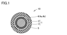
- FIG. 1 is a schematic cross-sectional view of a cable according to a first embodiment and a second embodiment.
- FIG. 2 is a schematic cross-sectional view of a cable according to a third embodiment.
- FIG. 3 is a diagram for explaining the vertical attachment of the metal tape.
- FIG. 4 is a diagram for explaining the horizontal winding of the metal tape.
- FIG. 5A is a schematic cross-sectional view of an example of a cable according to a fourth embodiment.
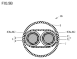
- FIG. 5B is a schematic cross-sectional view of another example of the cable according to the fourth embodiment.
- FIG. 6A is a schematic cross-sectional view of an example of a cable according to a fifth embodiment.
- FIG. 6B is a schematic cross-sectional view of another example of the cable according to the fifth embodiment.
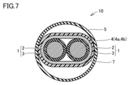
- FIG. 7 is a schematic cross-sectional view of a cable according to a sixth embodiment.
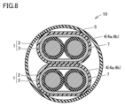
- FIG. 8 is a schematic cross-sectional view of another example of the cable according to the sixth embodiment.
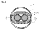
- FIG. 9 is a schematic cross-sectional view of a cable according to the seventh embodiment.
- FIG. 10 is a schematic cross-sectional view of another example of the cable according to the seventh embodiment.
- FIG. 11A is a cross-sectional view of an example of a test structure used in an insulation degradation suppression evaluation test.
- FIG. 11B is a cross-sectional view of another example of a test structure used in an insulation degradation suppression evaluation test.
- the present disclosure therefore aims to provide a cable in which the dielectric tangent of the cable insulation does not increase and degradation of the cable insulation is suppressed, even when the cable is bundled with a wire harness having insulation made of PVC.
- Degradation of the insulation refers to both heat aging and degradation caused by harmful gases generated by PVC.
- the cable of the present disclosure has A cable comprising an electric wire and a metal layer covering the electric wire,
- the electric wire includes a conductor and an insulating material provided on an outer peripheral surface of the conductor,
- the insulating material includes a polyolefin resin, a phenolic antioxidant, and a copper inhibitor;
- the content of the polyolefin resin in the insulating material is 98% by mass or more, the insulating material contains, relative to 100 parts by mass of the polyolefin resin, 0.01 parts by mass or more and 0.5 parts by mass or less of the phenol-based antioxidant and 0.01 parts by mass or more and 0.5 parts by mass or less of the copper inhibitor, and has a dielectric loss tangent at 10 GHz of 3.0 ⁇ 10-4 or less;
- the metal layer includes a longitudinally attached metal layer formed by longitudinally attaching a metal tape, The metal tapes overlap each other in a width direction of the metal
- the cable of the present disclosure is A cable comprising an electric wire and a metal layer covering the electric wire,
- the electric wire includes a conductor and an insulating material provided on an outer peripheral surface of the conductor,
- the insulating material includes a polyolefin resin, a phenolic antioxidant, and a copper inhibitor;
- the content of the polyolefin resin in the insulating material is 98% by mass or more, the insulating material contains, relative to 100 parts by mass of the polyolefin resin, 0.01 parts by mass or more and 0.5 parts by mass or less of the phenol-based antioxidant and 0.01 parts by mass or more and 0.5 parts by mass or less of the copper inhibitor, and has a dielectric loss tangent at 10 GHz of 3.0 ⁇ 10-4 or less;
- the metal layer includes a horizontally wound metal layer formed by horizontally winding a metal tape, The metal tapes overlap each other in a width direction of the metal tapes to form an overlapping portion, The width of the overlapping portion is equal to
- the insulating material of the cable disclosed herein contains a polyolefin resin and a phenolic antioxidant.
- the amount of the phenolic antioxidant is 0.01 parts by mass or more and 0.5 parts by mass or less per 100 parts by mass of the polyolefin resin, so the amount of the phenolic antioxidant is small. Therefore, the dielectric tangent of the insulating material does not increase, and oxidative deterioration of the insulating material is suppressed.
- the metal layer of the cable disclosed herein also has a shielding effect to prevent hydrochloric acid gas generated from the PVC of the surrounding wire harness from penetrating into the inside of the cable. This prevents hydrochloric acid gas from reaching the insulation of the cable, suppressing deterioration of the insulation.
- the metal layer of the cable disclosed herein also has a noise blocking effect. Therefore, the cable disclosed herein can transmit signals reliably.
- the cable disclosed herein has a small dielectric tangent and is particularly suitable for high-speed transmission.
- the cable includes a plurality of the electric wires
- the metal layer may cover each of the wires.
- the cable has a first electric wire group consisting of two or more electric wires,
- the metal layer may collectively cover the first group of electric wires.
- the cable may further include a metal braid covering the surface of the metal layer opposite to the surface facing the electric wire.
- This provides a higher noise shielding effect and makes wiring easier and easier to bend.
- the metal tape includes a thin metal layer,
- the metal thin layer may have a thickness of 0.1 ⁇ m or more and 20 ⁇ m or less.
- the polyolefin resin may be a polypropylene resin.
- the cable further includes an outer sheath covering the metal layer.
- the outer covering material contains a polyolefin resin and a metal hydroxide,
- the metal hydroxide is at least one selected from the group consisting of magnesium hydroxide and aluminum hydroxide,
- the outer covering material may contain 50 parts by mass or more and 200 parts by mass or less of the metal hydroxide per 100 parts by mass of the polyolefin resin.
- the metal tape includes a laminated structure in which a base film, an adhesive layer, and a thin metal layer are laminated in the above order,
- the base film is made of polyethylene terephthalate,
- the thin metal layer may include aluminum or copper.
- the metal tape may be aluminum foil or copper foil.
- the cable includes two of the electric wires, The two electric wires may be twisted in a pair.
- the cable includes two of the electric wires,
- the two electric wires may be laterally wound with a resin tape.
- a ⁇ B means the upper and lower limits of a range (i.e., greater than or equal to A and less than or equal to B). If no unit is stated for A and only a unit is stated for B, the units of A and B are the same.
- any one numerical value listed as the lower limit and any one numerical value listed as the upper limit is also considered to be disclosed.
- a1 or more, b1 or more, and c1 or more are listed as the lower limit and a2 or less, b2 or less, and c2 or less are listed as the upper limit, a1 or more and a2 or less, a1 or more and b2 or less, a1 or more and c2 or less, b1 or more and a2 or less, b1 or more and b2 or less, b1 or more and c2 or less, c1 or more and a2 or less, c1 or more and b2 or less, and c1 or more and c2 or less are considered to be disclosed.
- Fig. 1 is a schematic cross-sectional view of a cable 10 according to embodiment 1.
- the cable 10 according to embodiment 1 includes an electric wire 1, a metal layer 4 covering the electric wire 1, and an outer covering material 5.
- the electric wire 1 includes one conductor 2 and an insulating material 3 provided on the outer peripheral surface of the conductor 2.
- the metal layer 4 includes a vertically attached metal layer 4a formed by vertically attaching a metal tape. The metal tapes partially overlap in the width direction of the metal tape to form an overlapping portion, and the width of the overlapping portion is 1/20 to 1/3 of the width of the metal tape.
- an electric wire 1 includes one conductor 2 and an insulating material 3 provided on the outer peripheral surface of the conductor 2 .
- the material of the conductor 2 is preferably a metal material having high electrical conductivity and high mechanical strength. Examples of such metal materials include copper, copper alloys, aluminum, aluminum alloys, nickel, silver, soft iron, steel, and stainless steel.
- the conductor 2 can be a wire material formed into a wire shape from one type of metal material.
- the conductor 2 can also be a multilayer structure in which the wire material is further coated with another metal by a technique such as plating. Examples of the conductor 2 having a multilayer structure include a tin-plated copper wire, a nickel-plated copper wire, a silver-plated copper wire, a copper-plated aluminum wire, and a copper-plated steel wire.
- the shape of the conductor 2 is not particularly limited, and any shape known in the art can be used. Examples of the shape of the conductor 2 include a round wire with a circular cross section, a rectangular wire with a square cross section, a rectangular flat wire, and a twisted wire made by twisting together multiple strands.
- the average cross-sectional area of the conductor 2 is not particularly limited and can be appropriately selected depending on the application.
- the average cross-sectional area of the conductor 2 may be 0.01 mm2 or more and 10 mm2 or less, or 0.1 mm2 or more and 10 mm2 or less.
- the method for measuring the average cross-sectional area of the conductor 2 is as follows. One conductor 2 is stretched in a straight line, cut along a plane that connects one end of the conductor 2 to the other end of the conductor 2 with a first direction as a normal line, and the cross section is exposed to measure the cross-sectional area.
- the conductor 2 is cut along a plane that connects one end of the conductor 2 to the other end of the conductor 2 with the first direction as a normal line at any five points to measure the cross-sectional area, and the average value is calculated.
- the average value corresponds to the average cross-sectional area of the conductor 2.
- the insulating material 3 is provided on the outer peripheral surface of the conductor 2 .
- the insulating material 3 may contain a polyolefin resin, a phenolic antioxidant, and a copper inhibitor.
- polyolefin resins examples include polypropylene, polypropylene thermoplastic elastomers, reactor-type polypropylene thermoplastic elastomers, dynamically crosslinked polypropylene thermoplastic elastomers, polyethylene (high density polyethylene (HDPE), linear low density polyethylene (LLDPE), low density polyethylene (LDPE), very low density polyethylene (VLDPE)), ethylene-propylene copolymers, polymethylpentene, ethylene-vinyl acetate copolymers, ethylene-ethyl acrylate copolymers, ethylene-methyl methacrylate copolymers, ethylene-methyl acrylate copolymers, ethylene-ethyl methacrylate copolymers, ethylene-butyl acrylate copolymers, ethylene-propylene rubbers, ethylene-acrylic rubbers, ethylene-glycidyl methacrylate copolymers, and polyethylene resins such as ethylene-meth
- High density polyethylene refers to polyethylene having a density of 0.942 g/cm3 or more .
- Linear low density polyethylene (LLDPE) refers to polyethylene having a density of 0.910 g/cm3 or more and less than 0.930 g/ cm3 , obtained by copolymerizing ethylene and an ⁇ -olefin.
- Low density polyethylene (LDPE) refers to polyethylene having a density of 0.910 g/cm3 or more and less than 0.930 g/ cm3 , obtained by polymerizing ethylene by a high pressure polymerization method.
- VLDPE Very low density polyethylene
- Polymethylpentene includes, for example, a homopolymer of 4-methyl-1-pentene, and a copolymer of 4-methyl-1-pentene with 3-methyl-1-pentene or other ⁇ -olefins.
- the ⁇ -olefin include propylene, butene, pentene, hexene, heptene, octene, vinyl acetate, methyl acrylate, ethyl acrylate, methyl methacrylate, and ethyl methacrylate.
- One type of polyolefin resin may be used, or two or more types may be used.
- the polyolefin resin may be polypropylene.
- polypropylene include homopolypropylene, random polypropylene, and block polypropylene.
- Homopolypropylene is a homopolymer of propylene.
- random polypropylene include copolymers of propylene and ethylene or ⁇ -olefins having 4 to 20 carbon atoms.
- Block polypropylene is a resin consisting of a homopolypropylene copolymer as the main component, a random copolymer elastomer as a component, and an ethylene polymer as an optional component.
- the mechanical strength is better when block polypropylene or homopolypropylene is used.
- the olefin resin is polypropylene, the effect of reducing the dielectric tangent of the insulating material 3 and the heat resistance can be further improved.
- the "main component" means the component with the largest content.
- the lower limit of the polyolefin resin content of the insulating material 3 is 98% by mass or more, and may be 99% by mass or more. When the polyolefin resin content is 98% by mass or more, the dielectric tangent of the insulating material 3 can be reduced satisfactorily.
- the upper limit of the polyolefin resin content may be 99.98% by mass or less, and may be 99.99% by mass or less. When the polyolefin resin content is 99.98% by mass or less, the content of the antioxidant, etc. in the insulating material 3 can be secured, and the oxidation deterioration resistance and heat resistance of the insulating material 3 become even better.
- the polyolefin resin content of the insulating material 3 may be 98% by mass or more and 99.99% by mass or less, and may be 99% by mass or more and 99.98% by mass or less.
- the above polyolefin resin content means the total content of the two or more types of polyolefin resins.
- the insulating material 3 may contain resins other than polyolefin resins.
- the insulating material 3 may contain polytetrafluoroethylene, acrylic resin, fluororubber, etc. as a processability improver in a range of 0.01% by mass to 2.0% by mass.
- the phenol-based antioxidant has a function of preventing oxidation of polyolefin-based resin, which is easily oxidized.
- the insulating material 3 contains a phenol-based antioxidant, it is possible to suppress oxidative deterioration of the polyolefin-based resin.
- the phenolic antioxidant is not particularly limited, and known phenolic antioxidants can be used.
- phenolic antioxidants include 3,9-bis[2- ⁇ 3-(3-tert-butyl-4-hydroxy-5-methylphenyl)propionyloxy ⁇ -1,1-dimethylethyl]-2,4,8,10-tetraoxaspiro[5,5]undecane (e.g., "Sumilizer GA-80" (trademark) manufactured by Sumitomo Chemical Co., Ltd., and "Adekastab AO-80” (trademark) manufactured by ADEKA Corporation), ethylenebis(oxyethylene)bis[3-(5-tert-butyl- hydroxy-m-tolyl)propionate] ("Irganox 245" (trademark) manufactured by BASF Japan Ltd.), triethylene glycol bis[3-(3-tert-butyl-4-hydroxy-5-methylphenyl)propionate] (for example, "ADEKA STAB AO-70" (trade
- the amount of the phenolic antioxidant to be blended per 100 parts by mass of the polyolefin resin is 0.01 parts by mass or more and 0.5 parts by mass or less.
- the antioxidant effect of the polyolefin resin is further improved.
- the amount of the phenolic antioxidant to be blended is 0.5 parts by mass or less, the increase in the dielectric tangent of the insulating material 3 due to the antioxidant can be suppressed, and the transmission characteristics of the cable 10 can be further improved.
- the lower limit of the amount of the phenolic antioxidant to be blended per 100 parts by mass of the polyolefin resin is 0.01 parts by mass or more, and may be 0.010 parts by mass or more, or may be 0.05 parts by mass or more.
- the upper limit of the amount of the phenolic antioxidant to be blended per 100 parts by mass of the polyolefin resin is 0.5 parts by mass or less and may be 0.3 parts by mass or less.
- the amount of the phenolic antioxidant to be blended per 100 parts by mass of the polyolefin resin may be 0.05 parts by mass or more and 0.3 parts by mass or less.
- the blending amount of the phenolic antioxidants refers to the total content of the two or more phenolic antioxidants.
- the insulating material 3 may contain an antioxidant other than a phenol-based antioxidant.
- the insulating material 3 may contain, for example, a sulfur-based antioxidant excluding a sulfur-containing phenol-based antioxidant.
- the copper inhibitor stabilizes copper ions by forming a chelate, and suppresses deterioration of the resin contained in the insulating material 3 caused by copper ions, i.e., so-called copper damage.
- the insulating material 3 further contains a copper inhibitor, copper damage can be suppressed, and oxidative deterioration of the polyolefin resin can be suppressed.
- copper inhibitors there are no particular limitations on the copper inhibitor, and known copper inhibitors can be used.
- copper inhibitors include salicylic acid derivatives, phthalic acid derivatives, triazole compound complexes, and aromatic secondary amine compounds.
- salicylic acid derivatives include N-N'-bis[3-(3,5-di-t-butyl-4-hydroxyphenyl)propionyl]hydrazine (BASF Japan's "Irganox MD1024" (trademark), etc.), 3-(N-salicyloyl)amino-1,2,4-triazole (ADEKA's "Adekastab CDA-1"), and decamethylenedicarboxylic acid disalicyloyl hydrazide (ADEKA's "Adekastab CDA-6").
- An example of a compound of triazole-based compounds is a compound mainly composed of 2-hydroxy-N-1H-1,2,4-triazole-3-ylbenzamide (ADEKA CORPORATION's "ADEKA STAB CDA-1M” (trademark)).
- An example of an aromatic secondary amine compound is N,N'-di-2-naphthyl-p-phenylenediamine (Ouchi Shinko Chemical Industry Co., Ltd.'s "Nocrac White” (trademark)).
- the amount of copper damage inhibitor to be blended per 100 parts by mass of polyolefin resin is 0.01 parts by mass or more and 0.5 parts by mass or less.
- the amount of copper damage inhibitor to be blended is 0.01 parts by mass or more, the copper damage prevention effect is further improved.
- the amount of copper damage inhibitor to be blended is 0.5 parts by mass or less, the occurrence of so-called bloom, in which the copper damage additive precipitates and crystallizes on the surface of the insulating material 3 in the insulating material 3, is suppressed, and the quality of the insulating material 3 is easily ensured.
- the lower limit of the amount of copper damage inhibitor to be blended per 100 parts by mass of polyolefin resin may be 0.010 parts by mass or more, or may be 0.05 parts by mass or more.
- the upper limit of the amount of copper damage inhibitor to be blended per 100 parts by mass of polyolefin resin may be 0.3 parts by mass or less.
- the amount of copper damage inhibitor to be blended per 100 parts by mass of polyolefin resin may be 0.05 parts by mass or more and 0.3 parts by mass or less.
- the insulating material 3 may contain metal inhibitors other than copper inhibitors.
- the insulating material 3 may contain other components, such as processability improvers, lubricants, pigments, etc., in the range of 0.01 mass % or more and 2.0 mass % or less.
- the processability improver improves the extrusion processability of the insulating material 3.
- processability improvers include polytetrafluoroethylene, acrylic resin, and fluororubber.
- the lubricant improves the releasability of the insulating material 3 from the mixer and extruder.
- lubricants include paraffin, stearic acid, zinc stearate, fatty acid amide, etc.
- the pigment colors the insulating material 3.
- Various known pigments can be used, such as titanium oxide.
- the dielectric loss tangent of the insulating material 3 when a high frequency electric field of 10 GHz is applied is 3.0 ⁇ 10 ⁇ 4 or less, which can sufficiently improve the effect of reducing transmission loss.
- the upper limit of the relative dielectric constant of the insulating material 3 may be 2.5 or less, or may be 2.3 or less.
- dielectric tangent and “relative dielectric constant” are values measured according to a method conforming to JIS-R1641 (2007).
- the lower limit of the average thickness of the insulating material 3 may be 50 ⁇ m or more, or 100 ⁇ m or more. When the average thickness of the insulating material 3 is 50 ⁇ m or more, there is a tendency for sufficient insulation to be ensured.
- the upper limit of the average thickness of the insulating material 3 may be 1500 ⁇ m or less, or 1000 ⁇ m or less. When the average thickness of the insulating material 3 is 1500 ⁇ m or less, the volumetric efficiency of the cable 10 formed using the electric wire can be improved.
- the average thickness of the insulating material 3 may be 50 ⁇ m or more and 1500 ⁇ m or less, or 100 ⁇ m or more and 1000 ⁇ m or less.
- the method for measuring the average thickness of the insulating material 3 is as follows.
- a single conductor 2 is stretched in a straight line, and the conductor 2 is cut along a plane that connects one end of the conductor 2 to the other end and has a normal in a first direction, to expose the cross section.
- the thickness of the insulating material 3 is measured at three arbitrary points, and the average of these is calculated to obtain a first average value.
- the conductor 2 is cut along a plane that has a normal in the first direction at five arbitrary points to measure the first average value, and the average of these is calculated to obtain a second average value.
- the second average value corresponds to the average thickness of the insulating material 3.
- the cable 10 of the first embodiment includes a metal layer 4 that covers the electric wire 1.
- the metal layer 4 is a vertically attached metal layer 4a that is configured by vertically attaching a metal tape. As shown in Fig. 3, the metal tapes partially overlap each other in the width direction of the metal tape to form an overlapping portion 16, and the width W2 of the overlapping portion 16 is 1/20 to 1/3 of the width W1 of the metal tape.
- vertical attachment means wrapping the metal tape along the extension direction X of the electric wire 1 as shown in FIG. 3.
- width direction of the metal tape means the direction perpendicular to the extension direction of the metal tape.
- the width W1 of the metal tape can be appropriately selected depending on the outer circumferential length of the electric wire 1 to be covered and the width W2 of the overlapping portion where the metal tape overlaps.
- the lower limit of the width W1 of the metal tape may be 2 mm or more, or 3 mm or more.
- the upper limit of the width W1 of the metal tape may be 30 mm or less, 25 mm or less, or 20 mm or less.
- the width W1 of the metal tape may be 2 mm or more and 30 mm or less, 3 mm or more and 25 mm or less, or 2 mm or more and 20 mm or less.
- the width W1 of the metal tape means the shortest distance between a pair of first and second side edges extending in the extension direction of the metal tape.
- the metal tapes overlap in part in the width direction to form an overlapping portion, and there are no particular restrictions on the width W2 of the overlapping portion, so long as it is 1/20 to 1/3 of the width W1 of the metal tape.
- the width W2 of the overlapping portion may be, for example, 0.01 mm to 10 mm, or 0.015 mm to 8 mm. If the width W2 of the overlapping portion is 0.01 mm or more, the effect of suppressing deterioration of the insulating material 3 is improved. If the width W2 of the overlapping portion is 10 mm or less, the cable is easier to bend and costs are reduced.
- the metal tape may include a laminated structure in which a base film, an adhesive layer, and a thin metal layer are laminated in the above order.
- the metal tape may have a laminated structure in which an adhesive layer and a thin metal layer are laminated in the above order on one main surface of a tape-shaped base film.
- the metal tape which has adhesive applied to the surface of the base film opposite the thin metal layer, is wrapped around the electric wire and then fixed to the wire with adhesive. This is advantageous because the metal tape will not peel off from the electric wire.
- the base film can be made of polyethylene terephthalate.
- the thickness of the base film can be 1 ⁇ m or more and 20 ⁇ m or less.
- the material of the adhesive layer is not particularly limited as long as it can bond the base film and the metal foil, and any conventionally known material can be used.
- materials for the adhesive layer include acrylic resin, epoxy resin, urethane resin, polyolefin resin, cyanoacrylate resin, silicone resin, styrene-butadiene rubber, phenolic resin, nitrile rubber, polyamide resin, polyvinyl acetate resin, and polyvinyl alcohol resin.
- the thin metal layer may be made of aluminum or copper.
- the thin metal layer may be aluminum foil or copper foil.
- the thickness of the thin metal layer made of aluminum foil or copper foil may be 5 ⁇ m or more and 20 ⁇ m or less.
- the metal tape may be a base film having a metal vapor deposition layer formed thereon.
- the thin metal layer is made of a metal vapor deposition layer.
- the thickness of the thin metal layer made of a metal vapor deposition layer may be 0.5 ⁇ m or more and 2 ⁇ m or less.
- the surface of the metal tape that faces the electric wire 1 when wrapping the metal tape around the electric wire 1 may be the exposed surface on the base film side or the exposed surface on the thin metal layer side.
- the metal tape may be a single-layer structure made of aluminum foil or copper foil.
- the thickness of the aluminum foil or copper foil may be 0.1 ⁇ m or more and 20 ⁇ m or less.
- the cable 10 of the first embodiment can further include an outer covering material 5 that covers the metal layer 4.
- the outer covering material 5 can protect the electric wire 1 and the metal layer 4, and can impart functions such as flame retardancy and oil resistance. Furthermore, even when the cable 10 is bundled with a wire harness having an insulating material made of PVC, deterioration of the insulating material can be further suppressed.
- the outer covering material 5 may contain a polyolefin resin and a metal hydroxide.
- the polyolefin resin of the outer covering material 5 may be any of the polyolefin resins described above as the polyolefin resin used in the insulating material 3. One type of polyolefin resin may be used, or two or more types may be used.
- the polyolefin resin of the outer covering material 5 and the polyolefin resin of the insulating material 3 may be the same or different.
- the lower limit of the polyolefin resin content in the outer jacket material 5 may be 33% by mass or more, or 35% by mass or more. When the polyolefin resin content is 33% by mass or more, it is possible to maintain the mechanical properties, oil resistance, etc. of the outer jacket material 5 in a good condition.
- the upper limit of the polyolefin resin content may be 67% by mass or less, or 60% by mass or less. When the polyolefin resin content is 67% by mass or less, the flame retardancy is good. Furthermore, when the cable of embodiment 1 is bundled with a wire harness having an insulating material made of PVC, deterioration of the cable insulating material is further suppressed. When two or more types of polyolefin resins are used, the polyolefin resin content means the total content of the two or more types of polyolefin resins.
- the outer covering material 5 may contain resins other than polyolefin resins.
- the outer covering material 5 may contain polytetrafluoroethylene, acrylic resin, fluororubber, etc. as a processability improver in a range of 0.1% by mass to 5.0% by mass.
- Metal hydroxides undergo an endothermic dehydration reaction at high temperatures of 200° C. or higher, suppressing combustion of materials containing the metal hydroxide. Furthermore, when the jacket material contains a metal hydroxide, deterioration of the insulation material of the cable is further suppressed when the cable of embodiment 1 is bundled with a wire harness having an insulation material made of PVC.
- the metal hydroxide at least one selected from the group consisting of magnesium hydroxide and aluminum hydroxide can be used.
- the amount of metal hydroxide per 100 parts by mass of polyolefin resin may be 50 parts by mass or more and 200 parts by mass or less, or 80 parts by mass or more and 180 parts by mass or less.
- the amount of the metal hydroxide means the total content of the two or more types of metal hydroxide.
- the outer covering material 5 may contain other components such as halogen-based flame retardants, phosphorus-based flame retardants (red phosphorus, phosphate esters, sodium hypophosphite, etc.), intumescent flame retardants, flame retardant assistants (antimony trioxide, melamine cyanurate, zinc borate, zinc oxide, zinc hydroxystannate, etc.), inorganic fillers (calcium carbonate, talc, silica, clay, etc.), pigments, lubricants, antioxidants, copper damage inhibitors, ultraviolet absorbers, light stabilizers, etc.
- halogen-based flame retardants phosphorus-based flame retardants (red phosphorus, phosphate esters, sodium hypophosphite, etc.), intumescent flame retardants, flame retardant assistants (antimony trioxide, melamine cyanurate, zinc borate, zinc oxide, zinc hydroxystannate, etc.), inorganic fillers (calcium carbonate, talc, silica, clay,
- FIG. 1 is a schematic cross-sectional view of a cable 10 according to embodiment 2.
- the cable 10 according to embodiment 2 includes one electric wire 1 and a metal layer 4 covering the electric wire 1.
- the electric wire 1 includes one conductor 2 and an insulating material 3 provided on the outer peripheral surface of the conductor 2.
- the metal layer 4 includes a horizontally wound metal layer 4b formed by horizontally winding a metal tape.
- the metal tape partially overlaps in the width direction to form an overlapping portion, and the width W2 of the overlapping portion is 1/5 to 1/2 of the width W1 of the metal tape, and the turning angle of the metal tape is more than 0° and 80° or less.
- the cable 10 according to embodiment 2 suppresses deterioration of the insulating material 3 even when it is used in a bundle with a wire harness having an insulating material made of PVC.
- the cable 10 of the second embodiment can have the same configuration as that of the first embodiment, except that it includes a horizontal metal layer 4b instead of the vertical metal layer 4a of the first embodiment.
- the horizontal metal layer 4b will be described below.
- the metal layer 4 is made of a laterally wound metal layer 4b formed by laterally winding a metal tape. As shown in Fig. 3, the metal tape partially overlaps in the width direction of the metal tape to form an overlapping portion 16, the width W2 of the overlapping portion 16 is 1/5 to 1/2 of the width W1 of the metal tape, and the turning angle A of the metal tape is more than 0° and 80° or less.
- horizontal winding means winding a metal tape in a spiral shape around the outer circumference of the electric wire 1, as shown in FIG. 4.
- the metal tape may have the same configuration as in embodiment 1.
- the metal tapes overlap in part in the width direction to form an overlapping portion, and there are no particular limitations on the width W2 of the overlapping portion, so long as it is between 1/5 and 1/2 of the width W1 of the metal tape.
- the width W2 of the overlapping portion may be, for example, between 0.4 mm and 15 mm, or between 0.6 mm and 13 mm. If the width W2 of the overlapping portion is 0.4 mm or greater, the effect of suppressing deterioration of the insulating material 3 is improved. If the width W2 of the overlapping portion is 15 mm or less, the cable is easier to bend and costs are reduced.
- the rotation angle of the metal tape is greater than 0° and less than or equal to 80°, and may be greater than or equal to 7° and less than or equal to 80°.
- the rotation angle of the metal tape refers to the acute angle A between the extension direction X1 of the electric wire 1 and the side edge of the metal tape when the metal tape is wound laterally around the electric wire 1 and viewed in a plane as shown in FIG. 4.
- Fig. 3 is a schematic cross-sectional view of a cable 10 according to Embodiment 3.
- the cable 10 according to Embodiment 3 can have the same configuration as that of Embodiment 1 or 2, except that it further includes a metal braid 6 that covers the surface of the vertically-wound metal layer 4a or the horizontally-wound metal layer 4b opposite to the surface facing the electric wire 1.
- the metal braid 6 is disposed between the metal layer 4 and the jacket material 5.
- the metal braid 6 will be described below.
- the material of the metal braid that constitutes the metal braid 6 is preferably a metal material that has high electrical conductivity and high mechanical strength.
- metal materials include copper and copper alloys.
- the metal braid can be made by braiding a wire material formed into a linear shape of one type of metal material into a tube shape. It is also possible to use a multi-layer structure in which the wire material is further coated with another metal. Examples of wire materials having a multi-layer structure include tin-plated copper wire, nickel-plated copper wire, silver-plated copper wire, copper-plated aluminum wire, and copper-coated steel wire.
- FIG. 5A is a schematic cross-sectional view of an example of a cable 10 according to embodiment 4.
- Fig. 5A shows a configuration in which two electric wires are twisted together, that is, a so-called twisted pair.
- the dashed line indicates the outer edge 4c of the metal layer 4 that covers the electric wires that are not exposed in the cross section.
- Fig. 5B is a schematic cross-sectional view of another example of the cable according to embodiment 4.
- Fig. 5B shows a so-called two-core parallel configuration in which two electric wires are arranged in parallel.
- the cable 10 of the fourth embodiment includes two electric wires 1 and a metal layer 4 covering the two electric wires 1.
- the electric wire 1 includes a conductor 2 and an insulating material 3 provided on the outer peripheral surface of the conductor 2.
- the metal layer 4 is made of a vertically-wrapped metal layer 4a or a horizontally-wrapped metal layer 4b.
- the two electric wires 1 covered with the metal layer 4 have a resin tape 7 (e.g., PET tape) wound horizontally on the outside of the metal layer 4 so as to fix the relative positions of the two electric wires, and an outer sheath material 5 is provided on the outside of the resin tape 7. As shown in FIG.
- FIG. 6A is a cross-sectional view of an example of a cable 10 according to embodiment 5.
- Fig. 6A shows a configuration in which two electric wires are twisted together, that is, a so-called twisted pair.
- Fig. 6B is a schematic cross-sectional view of another example of the cable of embodiment 5.
- Fig. 6B shows a so-called two-core parallel configuration in which two electric wires are arranged in parallel.
- the cable 10 according to the fifth embodiment can have the same configuration as that of the fourth embodiment, except that it further includes a metal braid 6 that covers the outer periphery of the vertically wound metal layer 4a or the outer periphery of the horizontally wound metal layer 4b.
- the details of the metal braid 6 are as described in the third embodiment.
- FIG. 7 and 8 are schematic cross-sectional views of a cable 10 according to embodiment 6.
- the cable 10 according to embodiment 7 can have the same configuration as embodiment 1 or embodiment 2, except that the cable 10 has a first group of electric wires 1 consisting of two or more electric wires 1, and the first group of electric wires is collectively covered with a metal layer 4.
- a structure in which the first group of electric wires consisting of two or more electric wires 1 is collectively covered with a metal layer 4 is also referred to as a first structure.
- the metal layer 4 is vertically attached, it is preferable to press the tape wrapped vertically with the resin tape 7 so that it does not open.
- a wire group is shown in which the first structure is composed of two wires 1, but the number of wires 1 included in one wire group is not particularly limited and may include two or more depending on the application.
- one cable 10 includes one first structure, but the number of first structures included in one cable 10 is not particularly limited and may include two or more first structures depending on the application. For example, as shown in Figure 8, one cable 10 may include two first structures.
- FIG. 9 A cable according to another embodiment of the present disclosure (hereinafter also referred to as "embodiment 7") will be described with reference to Figs. 9 and 10.
- Figs. 9 and 10 are schematic cross-sectional views of a cable 10 according to embodiment 7.
- the cable 10 according to embodiment 7 can have the same configuration as embodiment 6, except that it further includes a metal braid 6 that covers the surface of the vertically-wound metal layer 4a or the horizontally-wound metal layer 4b opposite to the surface facing the electric wire 1.
- the details of the metal braid 6 are as described in embodiment 3.
- test samples were prepared in the following manner.
- a conductor was prepared as a twisted wire (AWG26) of seven single conductors made of tin-plated soft copper with a diameter of 0.16 mm.
- An insulating material with a thickness of 0.36 mm was formed on the outer surface of the conductor by extrusion molding to obtain an electric wire.
- the composition of the insulating material is as shown in the "Insulating material” column of Tables 1 and 2.
- the "polyolefin resin” in the “Insulating material” column of Tables 1 and 5 is block polypropylene, the "antioxidant” is a hindered phenol-based antioxidant, and the "copper inhibitor” is a copper inhibitor having a hydrazide structure.
- the insulating material was made using polyolefin resin, antioxidant, and copper inhibitor as raw materials, and no other components were used as raw materials.
- One or two electric wires were prepared for each sample. When two electric wires were prepared, the two electric wires were twisted together to form a twisted pair.
- a metal tape made of aluminum foil (corresponding to a thin metal layer) bonded to a PET (polyethylene terephthalate) base was wrapped around the outer periphery of the electric wire to form a vertically applied metal layer or a horizontally wound metal layer.
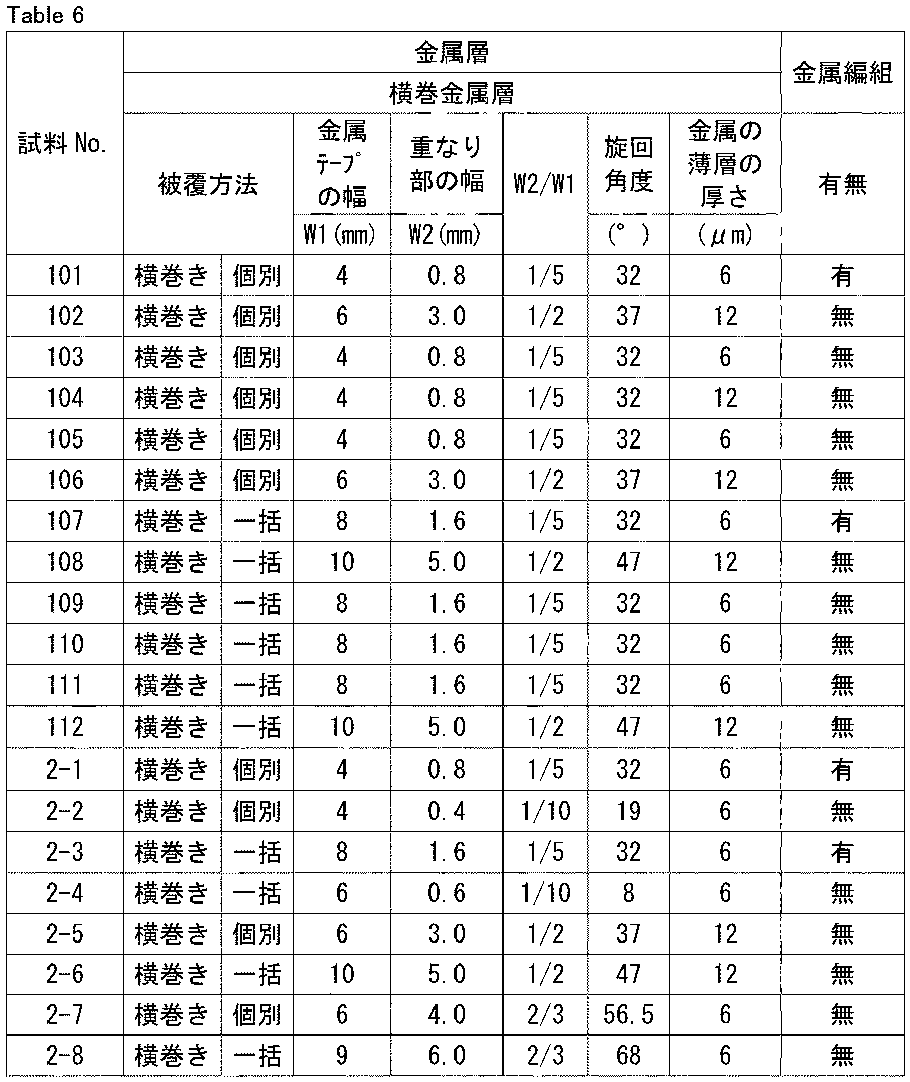
- the width W1 of the metal tape and the thickness of the aluminum foil (corresponding to a thin metal layer) are as shown in the "Width W1 of Metal Tape” and “Thickness of Thin Metal Layer” columns in Tables 2 and 6.
- the method of coating the metal tape for each sample is as shown in the “Coating Method” column in Tables 2 and 6.
- “Vertical” means that the metal tape was wrapped vertically around the outer periphery of the electric wire.
- the vertical metal layer or the horizontal metal layer was covered with a metal braid.
- the metal braid was made of tin-plated soft copper with a wire diameter of 0.1 mm and a thickness of 0.4 mm.
- two wires covered with metal tape were twisted together, and the two twisted wires were covered with a metal braid.
- the outer side of the metal layer or metal braid was extruded with an outer jacket material to a thickness of 0.6 mm to obtain a test sample.
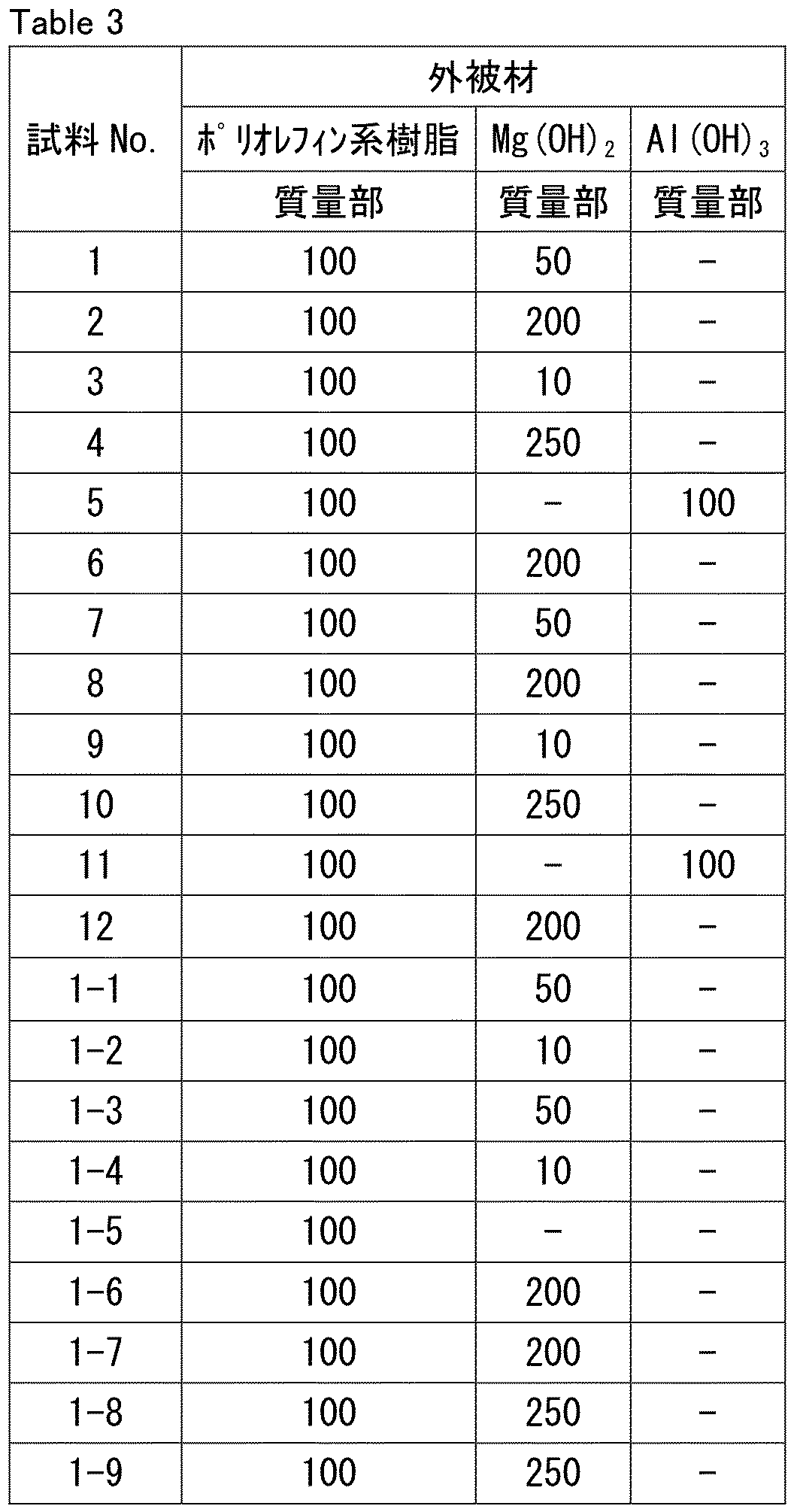
- the composition of the outer jacket material is as shown in the "Outer Jacket Material” column of Tables 3 and 7.
- the "Polyolefin-based resin” listed in the “Outer Jacket Material” column of Tables 3 and 7 is block polypropylene.
- the outer jacket material did not use any components other than the polyolefin-based resin, Mg(OH) 2 , and Al(OH 3 ) as raw materials.
- a single electric wire two electric wires covered with a metal tape were twisted together, and the two twisted electric wires were covered with an outer jacket.
- FIGS. 11A and 11B are cross-sectional views of a test structure 11 used in an insulation material degradation suppression evaluation test.
- FIG. 11A is a cross-sectional view of a test structure 11 when a test sample 12 with a single electric wire is used. As shown in FIG. 11A, the test structure 11 is made by bundling the test sample 12 and six PVC-coated electric wires 14 arranged to cover the periphery of the test sample 12 with PVC tape 15.
- Figure 11B is a cross-sectional view of a test structure when a test sample with two electric wires is used.
- the test structure 11 is made by bundling a test sample 12 and six PVC-coated electric wires 14 that are tightly attached so as to cover the periphery of the test sample 12 with PVC tape 15.
- the PVC-coated wire 14 consists of a conductor 2 (a strand of 65 tin-plated soft copper single conductors with a diameter of 0.32 mm, 3.0 mm in diameter) and a PVC insulation material 13 (diameter 4.6 mm) made of cross-linked polyvinyl chloride with a thickness of 0.8 mm that coats the outer circumference of the conductor 2.
- the PVC tape used for the test structure 11 was VTA tape (thickness 0.135 mm, width 19 mm) manufactured by Yazaki Corporation.
- the VTA tape was half-wrapped to bundle the test sample 12 and the PVC-coated wire 14 together to form the test structure 11.
- test structures 11 are left in an oven at 100°C and are removed after 1000 hours, 2000 hours, and 3000 hours.
- the test structures 11 are disassembled to remove the electric wires, which are then wound around half of the circumference of a self-diameter mandrel.
- the self-diameter mandrel means a mandrel with the same diameter as the electric wire.
- the length of the outer circumference of the electric wire wound around the self-diameter mandrel is extended by 1.5 times the length of the central part of the electric wire.
- the insulation of the electric wire wound around the self-diameter mandrel is visually observed for appearance abnormalities such as cracks, fissures, and exposed conductors, and the time when an appearance abnormality is observed is defined as the appearance abnormality appearance time.
- appearance abnormalities such as cracks, fissures, and exposed conductors
- the time when an appearance abnormality is observed is defined as the appearance abnormality appearance time.
- a heat aging test As the conductor, a stranded wire (AWG26) of seven single conductors with a diameter of 0.16 mm made of tin-plated soft copper was prepared. An insulating material with a thickness of 0.36 mm was formed on the outer peripheral surface of the conductor by extrusion molding to obtain an electric wire. The length of the electric wire was 350 mm. A heat aging test was performed on each sample electric wire based on the ISO6722 standard (Class B). As the heat aging test, a long-term aging test and a short-term aging test were performed. The test conditions for each test are as follows.
- a flexibility test sample was prepared by covering the test sample 12 in Fig. 11A and Fig. 11B with a resin tape 7.
- a compression test fixture was attached to a tensile tester, and the flexibility test sample was fixed to the fixture and evaluated by measuring the reaction force when bent at a bending radius of 25 mm.
- the evaluation criteria for bending performance were as follows: a bending reaction force of 1 N or less was considered to be acceptable, and a bending reaction force of more than 1 N was considered to be unacceptable.
- test specimen 12 shown in Fig. 11A and Fig. 11B was prepared.
- the strength of the outer covering material was measured by a scrape abrasion test based on the ISO 6722 standard. The test was performed with a needle diameter of 0.45 mm, a load of 7 N, and an operating speed of 55 cycles/min. A test that was repeated 200 times or more until the metal braid or metal tape was exposed was considered to have passed the test.
- test Insulation Sheet In order to measure the dielectric tangent and the relative dielectric constant of the insulating material used in the above test sample 12 and to perform a heat aging test, a test insulating sheet was prepared in the following manner.
- a polyolefin resin, an antioxidant, and a copper inhibitor were mixed in the ratio shown in the "Insulating Material” column of Tables 1 and 2 to obtain a resin composition for insulating material.
- the resin composition for insulating material was press molded to produce an insulating sheet for testing. The press molding conditions were preheating at 180°C for 5 minutes, followed by further pressure application at that temperature and holding for 5 minutes.
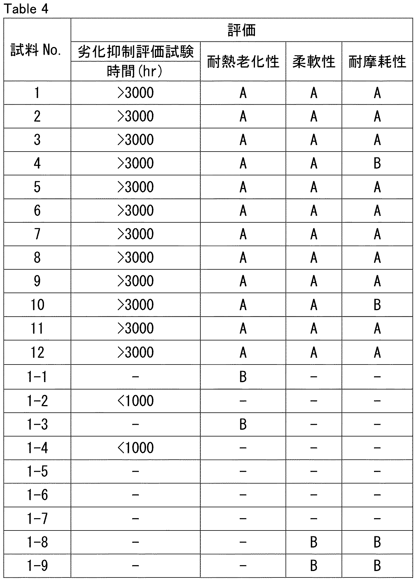
- Samples 1 to 12 and samples 101 to 112 correspond to examples. It was confirmed that samples 1 to 12 and samples 101 to 112 did not increase the dielectric tangent of the insulating material and had a high effect of suppressing deterioration of the insulating material.
- Samples 1-1 to 1-9 and Samples 2-1 to 2-8 are comparative examples. Samples 1-1, 1-3, 2-1, and 2-3 were evaluated as "B" in the heat aging test, failing the test, and therefore no other tests were performed. Samples 1-2, 1-4, 2-2, and 2-4 were not evaluated as they had poor degradation inhibition effects, and therefore no other tests were performed. Samples 1-5, 1-6, 1-7, 2-5, and 2-6 were not evaluated as they had a dielectric loss tangent of more than 3.0 ⁇ 10 ⁇ 4 . Samples 1-8, 1-9, 2-7, and 2-8 were evaluated as "B" in the flexibility test, failing the test, and therefore no tests were performed for degradation inhibition and heat aging resistance.
Landscapes
- Physics & Mathematics (AREA)
- Electromagnetism (AREA)
- Organic Insulating Materials (AREA)
Abstract
電線と、前記電線を被覆する金属層と、を備えるケーブルであって、前記電線は、導体と、前記導体の外周面に設けられた絶縁材と、を含み、前記絶縁材は、ポリオレフィン系樹脂、フェノール系酸化防止剤および銅害防止剤を含み、前記絶縁材の前記ポリオレフィン系樹脂の含有率は、98質量%以上であり、前記絶縁材は、前記ポリオレフィン系樹脂100質量部に対して、前記フェノール系酸化防止剤を0.01質量部以上0.5質量部以下、および、前記銅害防止剤を0.01質量部以上0.5質量部以下含み、10GHzにおける誘電正接が3.0×10⁻⁴以下であり、前記金属層は、金属テープを縦添えして構成される縦添え金属層を含み、前記金属テープは、前記金属テープの幅方向において一部重なりあって重なり部を形成し、前記重なり部の幅は、前記金属テープの幅の1/20以上1/3以下である、ケーブルである。
Description
本開示は、ケーブルに関する。本出願は、2023年6月29日に出願した日本特許出願である特願2023-106957号に基づく優先権を主張する。当該日本特許出願に記載された全ての記載内容は、参照によって本明細書に援用される。
自動車の自動運転技術や運転アシスト機能のニーズに伴い、車載情報電線ではより一層の情報伝送の容量の増大および高速化が求められている。車載情報電線は、銅などの金属からなる導体をポリオレフィン系樹脂からなる絶縁材で被覆したものである。伝送損失(伝送ロス)は、信号の周波数、および、絶縁材の誘電正接と正の相関を持つため、信号伝送の高速化のためには、絶縁材の誘電正接を低減し、伝送損失をより一層低減して、信号の伝送を安定的に行う必要がある。
車載情報電線は、一般的に、機械的保護及び難燃性、耐油性等の向上のために、1本または複数本の車載情報電線の上に外被材を被覆した車載用情報伝送ケーブルとして用いられる。車載用情報伝送ケーブルは、外被材にポリ塩化ビニル(以下、「PVC(polyvinyl chloride)」とも記す。)を用いた電線、ケーブルおよびワイヤーハーネスと束ねて用いられることがある。この場合、車載用情報伝送ケーブルの絶縁材に含まれる酸化防止剤が周囲の電線等のPVCに移行して車載用情報伝送ケーブルの絶縁材が酸化劣化したり、周囲の電線等のPVCから発生した塩酸ガスにより車載用情報伝送ケーブルの絶縁材の劣化が生じたりする場合がある。
特許文献1には、車載用情報伝送ケーブルを、PVCからなる絶縁材を有するワイヤーハーネスと束ねて用いた場合に、車載用情報伝送ケーブルの絶縁材の劣化を抑制する技術が開示されている。具体的には、絶縁材の劣化を抑制するために、絶縁材に多量の酸化防止剤を添加している。
本開示のケーブルは、
電線と、前記電線を被覆する金属層と、を備えるケーブルであって、
前記電線は、導体と、前記導体の外周面に設けられた絶縁材と、を含み、
前記絶縁材は、ポリオレフィン系樹脂、フェノール系酸化防止剤および銅害防止剤を含み、
前記絶縁材の前記ポリオレフィン系樹脂の含有率は、98質量%以上であり、
前記絶縁材は、前記ポリオレフィン系樹脂100質量部に対して、前記フェノール系酸化防止剤を0.01質量部以上0.5質量部以下、および、前記銅害防止剤を0.01質量部以上0.5質量部以下含み、10GHzにおける誘電正接が3.0×10⁻⁴以下であり、
前記金属層は、金属テープを縦添えして構成される縦添え金属層を含み、
前記金属テープは、前記金属テープの幅方向において一部重なりあって重なり部を形成し、
前記重なり部の幅は、前記金属テープの幅の1/20以上1/3以下である、ケーブルである。
電線と、前記電線を被覆する金属層と、を備えるケーブルであって、
前記電線は、導体と、前記導体の外周面に設けられた絶縁材と、を含み、
前記絶縁材は、ポリオレフィン系樹脂、フェノール系酸化防止剤および銅害防止剤を含み、
前記絶縁材の前記ポリオレフィン系樹脂の含有率は、98質量%以上であり、
前記絶縁材は、前記ポリオレフィン系樹脂100質量部に対して、前記フェノール系酸化防止剤を0.01質量部以上0.5質量部以下、および、前記銅害防止剤を0.01質量部以上0.5質量部以下含み、10GHzにおける誘電正接が3.0×10⁻⁴以下であり、
前記金属層は、金属テープを縦添えして構成される縦添え金属層を含み、
前記金属テープは、前記金属テープの幅方向において一部重なりあって重なり部を形成し、
前記重なり部の幅は、前記金属テープの幅の1/20以上1/3以下である、ケーブルである。
[本開示が解決しようとする課題]
酸化防止剤を多量に添加することは、絶縁材の誘電正接が増加して信号を高速で伝送することを妨げることにつながり好ましくない。
酸化防止剤を多量に添加することは、絶縁材の誘電正接が増加して信号を高速で伝送することを妨げることにつながり好ましくない。
そこで、本開示は、PVCからなる絶縁材を有するワイヤーハーネスと束ねて用いた場合においても、ケーブルの絶縁材の誘電正接が増加せず、かつケーブルの絶縁材の劣化が抑制されるケーブルを提供することを目的とする。ここでいう絶縁材の劣化は、耐熱老化とPVCから生じる有害ガス起因の劣化と両方を意味する。
[本開示の効果]
本開示によれば、PVCからなる絶縁材を有するワイヤーハーネスと束ねて用いた場合においても、ケーブルの絶縁材の誘電正接が増加せず、かつケーブルの絶縁材の劣化が抑制されるケーブルを提供することが可能となる。
本開示によれば、PVCからなる絶縁材を有するワイヤーハーネスと束ねて用いた場合においても、ケーブルの絶縁材の誘電正接が増加せず、かつケーブルの絶縁材の劣化が抑制されるケーブルを提供することが可能となる。
[本開示の実施形態の説明]
最初に本開示の実施態様を列記して説明する。
(1)本開示のケーブルは、
電線と、前記電線を被覆する金属層と、を備えるケーブルであって、
前記電線は、導体と、前記導体の外周面に設けられた絶縁材と、を含み、
前記絶縁材は、ポリオレフィン系樹脂、フェノール系酸化防止剤および銅害防止剤を含み、
前記絶縁材の前記ポリオレフィン系樹脂の含有率は、98質量%以上であり、
前記絶縁材は、前記ポリオレフィン系樹脂100質量部に対して、前記フェノール系酸化防止剤を0.01質量部以上0.5質量部以下、および、前記銅害防止剤を0.01質量部以上0.5質量部以下含み、10GHzにおける誘電正接が3.0×10⁻⁴以下であり、
前記金属層は、金属テープを縦添えして構成される縦添え金属層を含み、
前記金属テープは、前記金属テープの幅方向において一部重なりあって重なり部を形成し、
前記重なり部の幅は、前記金属テープの幅の1/20以上1/3以下である、ケーブルである。
最初に本開示の実施態様を列記して説明する。
(1)本開示のケーブルは、
電線と、前記電線を被覆する金属層と、を備えるケーブルであって、
前記電線は、導体と、前記導体の外周面に設けられた絶縁材と、を含み、
前記絶縁材は、ポリオレフィン系樹脂、フェノール系酸化防止剤および銅害防止剤を含み、
前記絶縁材の前記ポリオレフィン系樹脂の含有率は、98質量%以上であり、
前記絶縁材は、前記ポリオレフィン系樹脂100質量部に対して、前記フェノール系酸化防止剤を0.01質量部以上0.5質量部以下、および、前記銅害防止剤を0.01質量部以上0.5質量部以下含み、10GHzにおける誘電正接が3.0×10⁻⁴以下であり、
前記金属層は、金属テープを縦添えして構成される縦添え金属層を含み、
前記金属テープは、前記金属テープの幅方向において一部重なりあって重なり部を形成し、
前記重なり部の幅は、前記金属テープの幅の1/20以上1/3以下である、ケーブルである。
(2)本開示のケーブルは、
電線と、前記電線を被覆する金属層と、を備えるケーブルであって、
前記電線は、導体と、前記導体の外周面に設けられた絶縁材と、を含み、
前記絶縁材は、ポリオレフィン系樹脂、フェノール系酸化防止剤および銅害防止剤を含み、
前記絶縁材の前記ポリオレフィン系樹脂の含有率は、98質量%以上であり、
前記絶縁材は、前記ポリオレフィン系樹脂100質量部に対して、前記フェノール系酸化防止剤を0.01質量部以上0.5質量部以下、および、前記銅害防止剤を0.01質量部以上0.5質量部以下含み、10GHzにおける誘電正接が3.0×10⁻⁴以下であり、
前記金属層は、金属テープを横巻きして構成される横巻金属層を含み、
前記金属テープは、前記金属テープの幅方向において一部重なりあって重なり部を形成し、
前記重なり部の幅は、前記金属テープの幅の1/5以上1/2以下であり、
前記金属テープの旋回角度は、0°超80°以下である、ケーブルである。
電線と、前記電線を被覆する金属層と、を備えるケーブルであって、
前記電線は、導体と、前記導体の外周面に設けられた絶縁材と、を含み、
前記絶縁材は、ポリオレフィン系樹脂、フェノール系酸化防止剤および銅害防止剤を含み、
前記絶縁材の前記ポリオレフィン系樹脂の含有率は、98質量%以上であり、
前記絶縁材は、前記ポリオレフィン系樹脂100質量部に対して、前記フェノール系酸化防止剤を0.01質量部以上0.5質量部以下、および、前記銅害防止剤を0.01質量部以上0.5質量部以下含み、10GHzにおける誘電正接が3.0×10⁻⁴以下であり、
前記金属層は、金属テープを横巻きして構成される横巻金属層を含み、
前記金属テープは、前記金属テープの幅方向において一部重なりあって重なり部を形成し、
前記重なり部の幅は、前記金属テープの幅の1/5以上1/2以下であり、
前記金属テープの旋回角度は、0°超80°以下である、ケーブルである。
上記(1)および(2)によれば、PVCからなる絶縁材を有するワイヤーハーネスと束ねて用いた場合においても、ケーブルの絶縁材の誘電正接が増加せず、かつケーブルの絶縁材の劣化が抑制されるケーブルを提供することが可能となる。この理由は、以下の通りと推察される。
本開示のケーブルの絶縁材は、ポリオレフィン系樹脂とフェノール系酸化防止剤とを含む。該絶縁材において、ポリオレフィン系樹脂100質量部に対して、フェノール系酸化防止剤は0.01質量部以上0.5質量部以下であり、フェノール系酸化防止剤の量が少ない。よって、絶縁材は誘電正接が増加することなく、絶縁材の酸化劣化が抑制される。
本開示のケーブルの金属層は、さらに、周囲のワイヤーハーネスのPVCから発生した塩酸ガスが、ケーブル内部に侵入することに対して遮蔽効果を有する。このため、塩酸ガスがケーブルの絶縁材に到達することなく、絶縁材の劣化が抑制される。
本開示のケーブルの金属層は、さらに、ノイズ遮断効果を有する。このため、本開示のケーブルは、確実に信号を伝送可能である。
本開示のケーブルは、誘電正接が小さく、特に高速伝送に適している。
(3)上記(1)または(2)において、前記ケーブルは、複数の前記電線を含み、
前記金属層は、前記電線のそれぞれを被覆してもよい。
前記金属層は、前記電線のそれぞれを被覆してもよい。
これによると、より高いノイズ遮蔽効果を得ることができる。
(4)上記(1)または(2)において、前記ケーブルは、2本以上の電線からなる第一電線群を有し、
前記金属層は、前記第一電線群を一括して被覆してもよい。
前記金属層は、前記第一電線群を一括して被覆してもよい。
これによると、コストを抑えつつ高いノイズ遮蔽効果を得ることができる。
(5)上記(1)から(4)のいずれかにおいて、前記ケーブルは、前記金属層の前記電線と対向する面と反対側の面を被覆する金属編組をさらに含んでもよい。
これによると、より高いノイズ遮蔽効果を得ることができ、曲げ易く配線を容易にできる。
(6)上記(1)から(5)のいずれかにおいて、前記金属テープは、金属薄層を含み、
前記金属薄層の厚さは、0.1μm以上20μm以下であってもよい。
前記金属薄層の厚さは、0.1μm以上20μm以下であってもよい。
これによると、金属テープの破損が抑制され、かつ、金属テープの柔軟性も良好である。
(7)上記(1)から(6)のいずれかにおいて、前記ポリオレフィン系樹脂はポリプロピレン樹脂であってもよい。
これによると、絶縁材の誘電正接および誘電率の増大が抑制され、ケーブルは優れた伝送特性を有することができる。
(8)上記(1)から(7)のいずれかにおいて、
前記ケーブルは、前記金属層を被覆する外被材をさらに備え、
前記外被材は、ポリオレフィン系樹脂および金属水酸化物を含み、
前記金属水酸化物は、水酸化マグネシウムおよび水酸化アルミニウムからなる群から選ばれる少なくとも1種であり、
前記外被材は、前記ポリオレフィン系樹脂100質量部に対して、前記金属水酸化物を50質量部以上200質量部以下含んでもよい。
前記ケーブルは、前記金属層を被覆する外被材をさらに備え、
前記外被材は、ポリオレフィン系樹脂および金属水酸化物を含み、
前記金属水酸化物は、水酸化マグネシウムおよび水酸化アルミニウムからなる群から選ばれる少なくとも1種であり、
前記外被材は、前記ポリオレフィン系樹脂100質量部に対して、前記金属水酸化物を50質量部以上200質量部以下含んでもよい。
これによると、電線および金属層を機械的に保護し、難燃性、耐油性等の機能を付与でき、更に、PVCからなる絶縁材を有するワイヤーハーネスと束ねて用いた場合においても、絶縁材の劣化が抑制されるケーブルを提供することが可能となる。
(9)上記(1)から(8)のいずれかにおいて、前記金属テープは、基材フィルムと、接着層と、金属薄層と、が前記の順で積層された積層構造を含み、
前記基材フィルムは、ポリエチレンテレフタレートからなり、
前記金属薄層は、アルミニウムまたは銅を含んでもよい。
前記基材フィルムは、ポリエチレンテレフタレートからなり、
前記金属薄層は、アルミニウムまたは銅を含んでもよい。
これによると、金属テープの破損が抑制され、かつ、金属テープの柔軟性も良好である。
(10)上記(1)から(8)のいずれかにおいて、前記金属テープは、アルミニウム箔または銅箔であってもよい。
これによると、金属テープの破損が抑制され、かつ、金属テープの柔軟性も良好で、かつ、コストを抑えることができる。
(11)上記(1)または(2)において、前記ケーブルは、2本の前記電線を含み、
前記2本の前記電線は対撚りされていてもよい。
前記2本の前記電線は対撚りされていてもよい。
(12)上記(1)または(2)において、前記ケーブルは、2本の前記電線を含み、
前記2本の前記電線は樹脂テープで横巻きされていてもよい。
前記2本の前記電線は樹脂テープで横巻きされていてもよい。
[本開示の実施形態の詳細]
本開示のケーブルの具体例を、以下に図面を参照しつつ説明する。本開示の図面において、同一の参照符号は、同一部分または相当部分を表すものである。また、長さ、幅、厚さ、深さなどの寸法関係は図面の明瞭化と簡略化のために適宜変更されており、必ずしも実際の寸法関係を表すものではない。
本開示のケーブルの具体例を、以下に図面を参照しつつ説明する。本開示の図面において、同一の参照符号は、同一部分または相当部分を表すものである。また、長さ、幅、厚さ、深さなどの寸法関係は図面の明瞭化と簡略化のために適宜変更されており、必ずしも実際の寸法関係を表すものではない。
本明細書において「A~B」という形式の表記は、範囲の上限下限(すなわちA以上B以下)を意味し、Aにおいて単位の記載がなく、Bにおいてのみ単位が記載されている場合、Aの単位とBの単位とは同じである。
本開示において、数値範囲下限および上限として、それぞれ1つ以上の数値が記載されている場合は、下限に記載されている任意の1つの数値と、上限に記載されている任意の1つの数値との組み合わせも開示されているものとする。例えば、下限として、a1以上、b1以上、c1以上が記載され、上限としてa2以下、b2以下、c2以下が記載されている場合は、a1以上a2以下、a1以上b2以下、a1以上c2以下、b1以上a2以下、b1以上b2以下、b1以上c2以下、c1以上a2以下、c1以上b2以下、c1以上c2以下が開示されているものとする。
[実施形態1]
<ケーブル>
本開示の一実施形態(以下「実施形態1」とも記す。)に係るケーブルについて、図1を用いて説明する。図1は、実施形態1に係るケーブル10の模式的断面図である。図1に示されるように、実施形態1に係るケーブル10は、電線1と、電線1を被覆する金属層4と、外被材5を備える。電線1は、1本の導体2と、導体2の外周面に設けられた絶縁材3と、を含む。金属層4は、金属テープを縦添えして構成される縦添え金属層4aを含む。金属テープは、金属テープの幅方向において一部重なりあって重なり部を形成し、重なり部の幅は、金属テープの幅の1/20以上1/3以下である。
<ケーブル>
本開示の一実施形態(以下「実施形態1」とも記す。)に係るケーブルについて、図1を用いて説明する。図1は、実施形態1に係るケーブル10の模式的断面図である。図1に示されるように、実施形態1に係るケーブル10は、電線1と、電線1を被覆する金属層4と、外被材5を備える。電線1は、1本の導体2と、導体2の外周面に設けられた絶縁材3と、を含む。金属層4は、金属テープを縦添えして構成される縦添え金属層4aを含む。金属テープは、金属テープの幅方向において一部重なりあって重なり部を形成し、重なり部の幅は、金属テープの幅の1/20以上1/3以下である。
<電線>
図1に示されるように、実施形態1のケーブル10において、電線1は1本の導体2と、導体2の外周面に設けられた絶縁材3と、を含む。
図1に示されるように、実施形態1のケーブル10において、電線1は1本の導体2と、導体2の外周面に設けられた絶縁材3と、を含む。
<導体>
導体2の材質は、導電率が高くかつ機械的強度が大きい金属材料が好ましい。このような金属材料としては、例えば、銅、銅合金、アルミニウム、アルミニウム合金、ニッケル、銀、軟鉄、鋼、ステンレス鋼が挙げられる。導体2は、1種の金属材料を線状に形成した線材とすることができる。また、導体2は、線材をめっきなどの技術により、更に別の金属で被覆した多層構造としたものを用いることもできる。多層構造を有する導体2としては、例えば、錫めっき銅線、ニッケルめっき銅線、銀めっき銅線、銅めっきアルミニウム線、銅めっき鋼線が挙げられる。
導体2の材質は、導電率が高くかつ機械的強度が大きい金属材料が好ましい。このような金属材料としては、例えば、銅、銅合金、アルミニウム、アルミニウム合金、ニッケル、銀、軟鉄、鋼、ステンレス鋼が挙げられる。導体2は、1種の金属材料を線状に形成した線材とすることができる。また、導体2は、線材をめっきなどの技術により、更に別の金属で被覆した多層構造としたものを用いることもできる。多層構造を有する導体2としては、例えば、錫めっき銅線、ニッケルめっき銅線、銀めっき銅線、銅めっきアルミニウム線、銅めっき鋼線が挙げられる。
導体2の形状は特に制限されず、従来公知の形状を用いることができる。導体2の形状は、例えば、断面が円形状の丸線、断面が正方形状の角線、長方形状の平角線、複数の素線を撚り合わせた撚り線が挙げられる。
導体2の平均断面積は特に制限されず、用途によって適宜選択することができる。導体2の平均断面積は、0.01mm2以上10mm2以下でもよく、0.1mm2以上10mm2以下でもよい。本開示において、導体2の平均断面積の測定方法は以下の通りである。1本の導体2を直線状にのばし、導体2の一方の端部から他方の端部をつなぐ第一方向を法線とする平面で導体2を切断し、断面を露出させて断面積を測定する。1本の導体2について、任意の5箇所で第一方向を法線とする平面で導体2を切断して断面積を測定し、平均値を算出する。該平均値が、導体2の平均断面積に該当する。
<絶縁材>
実施形態1のケーブル10において、絶縁材3は導体2の外周面に設けられる。
実施形態1のケーブル10において、絶縁材3は導体2の外周面に設けられる。
絶縁材3は、ポリオレフィン系樹脂、フェノール系酸化防止剤および銅害防止剤を含むことができる。
≪ポリオレフィン系樹脂≫
ポリオレフィン系樹脂としては、例えば、ポリプロピレン、ポリプロピレン系熱可塑性エラストマー、リアクター型ポリプロピレン系熱可塑性エラストマー、動的架橋型ポリプロピレン系熱可塑性エラストマー、ポリエチレン(高密度ポリエチレン(HDPE)、直鎖状低密度ポリエチレン(LLDPE)、低密度ポリエチレン(LDPE)、超低密度ポリエチレン(VLDPE))、エチレン-プロピレン共重合体、ポリメチルペンテン、エチレン-酢酸ビニル共重合体、エチレン-アクリル酸エチル共重合体、エチレン-メタクリル酸メチル共重合体、エチレン-アクリル酸メチル共重合体、エチレン-メタクリル酸エチル共重合体、エチレン-アクリル酸ブチル共重合体、エチレン-プロピレンゴム、エチレンアクリルゴム、エチレン-グリシジルメタクリレート共重合体、エチレン-メタクリル酸共重合体等のポリエチレン系樹脂、エチレン-メタクリル酸共重合体、エチレン-アクリル酸共重合体の分子間をナトリウムや亜鉛などの金属イオンで分子間結合したアイオノマー樹脂が挙げられる。ポリオレフィン系樹脂としては、これらの樹脂を無水マレイン酸等で変性したもの、これらの樹脂がエポキシ基、アミノ基、イミド基を有するものも用いることができる。
ポリオレフィン系樹脂としては、例えば、ポリプロピレン、ポリプロピレン系熱可塑性エラストマー、リアクター型ポリプロピレン系熱可塑性エラストマー、動的架橋型ポリプロピレン系熱可塑性エラストマー、ポリエチレン(高密度ポリエチレン(HDPE)、直鎖状低密度ポリエチレン(LLDPE)、低密度ポリエチレン(LDPE)、超低密度ポリエチレン(VLDPE))、エチレン-プロピレン共重合体、ポリメチルペンテン、エチレン-酢酸ビニル共重合体、エチレン-アクリル酸エチル共重合体、エチレン-メタクリル酸メチル共重合体、エチレン-アクリル酸メチル共重合体、エチレン-メタクリル酸エチル共重合体、エチレン-アクリル酸ブチル共重合体、エチレン-プロピレンゴム、エチレンアクリルゴム、エチレン-グリシジルメタクリレート共重合体、エチレン-メタクリル酸共重合体等のポリエチレン系樹脂、エチレン-メタクリル酸共重合体、エチレン-アクリル酸共重合体の分子間をナトリウムや亜鉛などの金属イオンで分子間結合したアイオノマー樹脂が挙げられる。ポリオレフィン系樹脂としては、これらの樹脂を無水マレイン酸等で変性したもの、これらの樹脂がエポキシ基、アミノ基、イミド基を有するものも用いることができる。
「高密度ポリエチレン(HDPE)」とは、密度が0.942g/cm3以上のポリエチレンをいう。「直鎖状低密度ポリエチレン(LLDPE)」とは、密度が0.910g/cm3以上0.930g/cm3未満であって、エチレンとα-オレフィンとを共重合して得られるポリエチレンをいう。「低密度ポリエチレン(LDPE)」とは、密度が0.910g/cm3以上0.930g/cm3未満であって、高圧重合法によりエチレンを重合して得られるポリエチレンをいう。「超低密度ポリエチレン(VLDPE)」とは、密度が0.870g/cm3以上0.910g/cm3未満のポリエチレンをいう。「ポリメチルペンテン」としては、例えば、4-メチル-1-ペンテンの単独重合体、4-メチル-1-ペンテンと3-メチル-1-ペンテンまたは他のα-オレフィンとの共重合体が挙げられる。α-オレフィンとしては、例えば、プロピレン、ブテン、ペンテン、ヘキセン、ヘプテン、オクテン、酢酸ビニル、アクリル酸メチル、アクリル酸エチル、メタクリル酸メチル、メタクリル酸エチルが挙げられる。
ポリオレフィン系樹脂は、1種を用いてもよいし、2種以上を用いてもよい。
ポリオレフィン系樹脂は、ポリプロピレンでもよい。ポリプロピレンとしては、例えば、ホモポリプロピレン、ランダムポリプロピレン、ブロックポリプロピレンが挙げられる。ホモポリプロピレンは、プロピレンの単独重合体である。ランダムポリプロピレンは、例えば、プロピレンと、エチレンもしくは炭素数が4~20のα-オレフィンとの共重合体が挙げられる。ブロックポリプロピレンは、主成分としてのホモポリプロピレン共重合体成分としてのランダム共重合体エラストマーおよび任意成分であるエチレン重合体からなる樹脂である。これらの中でも、ブロックポリプロピレンまたはホモポリプロピレンを用いると、機械強度がより良好である。オレフィン系樹脂がポリプロピレンであることで、絶縁材3の誘電正接の低減効果および耐熱性をより向上することができる。本開示において、「主成分」とは、最も含有量の多い成分を意味する。
絶縁材3のポリオレフィン系樹脂の含有率の下限は、98質量%以上であり、99質量%以上でもよい。ポリオレフィン系樹脂の含有率が98質量%以上であると、絶縁材3の誘電正接を良好に低減することが可能となる。ポリオレフィン系樹脂の含有量の上限は、99.98質量%以下でもよく、99.99質量%以下でもよい。ポリオレフィン系樹脂の含有量が99.98質量%以下であると、絶縁材3における酸化防止剤等の含有量を確保することができ、絶縁材3の耐酸化劣化性、および、耐熱性がさらに良好となる。絶縁材3のポリオレフィン系樹脂の含有率は、98質量%以上99.99質量%以下でもよく、99質量%以上99.98質量%以下でもよい。ポリオレフィン系樹脂を2種以上用いている場合、上記ポリオレフィン系樹脂の含有率は、2種以上のポリオレフィン系樹脂の合計含有率を意味する。
絶縁材3は、ポリオレフィン系樹脂以外の樹脂を含んでもよい。絶縁材3は、例えば、ポリテトラフルオロエチレン、アクリル樹脂、フッ素ゴムなどを加工性改良剤として0.01質量%以上2.0質量%以下の範囲で含んでもよい。
≪フェノール系酸化防止剤≫
フェノール系酸化防止剤は、酸化しやすいポリオレフィン系樹脂の酸化を防止する機能を有する。絶縁材3がフェノール系酸化防止剤を含有することで、ポリオレフィン系樹脂の酸化劣化を抑制できる。
フェノール系酸化防止剤は、酸化しやすいポリオレフィン系樹脂の酸化を防止する機能を有する。絶縁材3がフェノール系酸化防止剤を含有することで、ポリオレフィン系樹脂の酸化劣化を抑制できる。
フェノール系酸化防止剤は特に制限されず、公知のフェノール系酸化防止剤を用いることができる。フェノール系酸化防止剤としては、例えば、3,9-ビス[2-{3-(3-tert-ブチル-4-ヒドロキシ-5-メチルフェニル)プロピオニルオキシ}-1,1-ジメチルエチル]-2,4,8,10-テトラオキサスピロ[5,5]ウンデカン(例えば、住友化学社製「スミライザーGA-80」(商標)、ADEKA社製「アデカスタブAO-80」(商標))、エチレンビス(オキシエチエレン)ビス[3-(5-tert-ブチル-ヒドロキシ-m-トリル)プロピオネート](BASFジャパン社製「イルガノックス245」(商標))、トリエチレングリコールビス[3-(3-tert-ブチル-4-ヒドロキシ-5-メチルフェニル)プロピオネート](例えば、ADEKA社製「アデカスタブAO-70」(商標))、1,3,5-トリ(3,5-ジ-tert-ブチル-4-ヒドロキシベンジル)-1,3,5-トリアジン-2,4,6(1H,3H,5H)-トリオン](例えば、ADEKA社製「アデカスタブAO-60」(商標))、4,4’-チオビス(6-tert-ブチル-m-クレゾール)(例えば、住友化学社製「スミライザーWX-R」(商標))、4,4’-ブチリデンビス(3-メチル-6-tert-ブチルフェノール)(例えば、大内新興化学工業社製「ノクラックNS-30」(商標)、ADEKA社製「アデカスタブAO-40」(商標))、4,4’-チオビス(3-メチル-6-tert-ブチル)フェノール(例えば、大内新興化学工業社製「ノクラック300」(商標))、1,1,3-トリス-(2-メチル-4-ヒドロキシ-5-tert-ブチルフェニル)ブタン(例えば、ADEKA社製「アデカスタブAO-30」(商標))、ビス[3,3-ビス(3-tert-ブチル-4-ヒドロキシフェニル)酪酸]エチレン(例えば、クラリアントケミカルズ社製「HOSTANOX O3」(商標))が挙げられる。
フェノール系酸化防止剤は、1種を用いてもよいし、2種以上を用いてもよい。
絶縁材3において、ポリオレフィン系樹脂100質量部に対するフェノール系酸化防止剤の配合量は、0.01質量部以上0.5質量部以下である。フェノール系酸化防止剤の配合量が0.01質量部以上であると、ポリオレフィン系樹脂の酸化防止効果がさらに向上する。フェノール系酸化防止剤の配合量が0.5質量部以下であると、酸化防止剤による絶縁材3の誘電正接を増加を抑制することができ、ケーブル10の送電特性をさらに向上させることができる。ポリオレフィン系樹脂100質量部に対するフェノール系酸化防止剤の配合量の下限は、0.01質量部以上でであり、0.010質量部以上でもよく、0.05質量部以上でもよい。ポリオレフィン系樹脂100質量部に対するフェノール系酸化防止剤の配合量の上限は、0.5質量部以下であり、0.3質量部以下でもよい。ポリオレフィン系樹脂100質量部に対するフェノール系酸化防止剤の配合量は、0.05質量部以上0.3質量部以下でもよい。フェノール系酸化防止剤を2種以上用いている場合、上記フェノール系酸化防止剤の配合量は、2種以上のフェノール系酸化防止剤の合計含有量を意味する。
絶縁材3は、フェノール系酸化防止剤以外の酸化防止剤を含んでもよい。絶縁材3は、例えば、硫黄含有フェノール系酸化防止剤を除く硫黄系酸化防止剤を含んでもよい。
≪銅害防止剤≫
銅害防止剤は、銅イオンをキレート形成により安定化し、銅イオンに起因する絶縁材3に含まれる樹脂の劣化、いわゆる銅害を抑制する。絶縁材3が銅害防止剤をさらに含有することで、銅害を抑制し、ポリオレフィン系樹脂の酸化劣化を抑制できる。
銅害防止剤は、銅イオンをキレート形成により安定化し、銅イオンに起因する絶縁材3に含まれる樹脂の劣化、いわゆる銅害を抑制する。絶縁材3が銅害防止剤をさらに含有することで、銅害を抑制し、ポリオレフィン系樹脂の酸化劣化を抑制できる。
銅害防止剤は特に制限されず、公知の銅害防止剤を用いることができる。銅害防止剤としては、例えば、サリチル酸誘導体、フタル酸誘導体、トリアゾール系化合物の複合物、芳香族第二級アミン系化合物が挙げられる。サリチル酸誘導体としては、例えば、NN’-ビス[3-(3、5-ジ-t-ブチル-4-ヒドロキシフェニル)プロピオニル]ヒドラジン(BASFジャパン社製「イルガノックスMD1024」(商標)など)、3-(N-サリチロイル)アミノ-1,2,4-トリアゾール(ADEKA社製「アデカスタブCDA-1」)、デカメチレンジカルボン酸ジサリチロイルヒドラジド(ADEKA社製「アデカスタブCDA-6」)が挙げられる。トリアゾール系化合物の複合物としては、例えば、2-ヒドロキシ-N-1H-1,2,4-トリアゾール-3-イルベンズアミドを主成分とする複合物(ADEKA社製「アデカスタブCDA-1M」(商標))が挙げられる。芳香族第二級アミン系化合物としては、例えば、N,N’-ジ-2-ナフチル-p-フェニレンジアミン(大内新興化学工業社製「ノクラックWhite」(商標))等が挙げられる。
銅害防止剤は、1種を用いてもよいし、2種以上を用いてもよい。
絶縁材3において、ポリオレフィン系樹脂100質量部に対する銅害防止剤の配合量は、0.01質量部以上0.5質量部以下である。銅害防止剤の配合量が0.01質量部以上であると、銅害防止効果がさらに向上する。銅害防止剤の配合量が0.5質量部以下であると、絶縁材3において銅害添加剤が表面に析出して結晶化する、いわゆるブルームの発生を抑制し、絶縁材3の品質を確保しやすい。ポリオレフィン系樹脂100質量部に対する銅害防止剤の配合量の下限は、0.010質量部以上でもよく、0.05質量部以上でもよい。ポリオレフィン系樹脂100質量部に対する銅害防止剤の配合量の上限は、0.3質量部以下でもよい。ポリオレフィン系樹脂100質量部に対する銅害防止剤の配合量は、0.05質量部以上0.3質量部以下でもよい。銅害防止剤を2種以上用いている場合、上記銅害防止剤の配合量は、2種以上の銅害防止剤の合計含有量を意味する。
絶縁材3は、銅害防止剤以外の金属害防止剤を含んでもよい。
≪その他の成分≫
絶縁材3は、ポリオレフィン系樹脂、フェノール系酸化防止剤および銅害防止剤に加えて、その他の成分として、例えば加工性改良剤、滑剤、顔料等を0.01質量%以上2.0質量%以下の範囲で含有してもよい。
絶縁材3は、ポリオレフィン系樹脂、フェノール系酸化防止剤および銅害防止剤に加えて、その他の成分として、例えば加工性改良剤、滑剤、顔料等を0.01質量%以上2.0質量%以下の範囲で含有してもよい。
加工性改良剤は、絶縁材3の押出加工性を向上させるものである。加工性改良剤としては、例えばポリテトラフルオロエチレン、アクリル樹脂、フッ素ゴムなどが挙げられる。
滑剤は、絶縁材3の混合機、押出機からの離型性を向上させるものである。滑剤としては、パラフィン、ステアリン酸、ステアリン酸亜鉛、脂肪酸アミド等が挙げられる。
顔料は、絶縁材3を着色するものである。顔料としては、公知の種々のものを使用することができ、例えば、酸化チタンが挙げられる。
周波数10GHzの高周波電界を印加した場合における絶縁材3の誘電正接は、3.0×10⁻⁴以下である。これによると、伝送損失の低減効果を十分に向上できる。
絶縁材3の比誘電率の上限は、2.5以下でもよく、2.3以下でもよい。絶縁材3の比誘電率が2.5以下であることで、伝送損失の低減効果を十分に向上できる。
上記「誘電正接」および「比誘電率」は、それぞれJIS-R1641(2007)に準ずる方法に従って測定される値である。
絶縁材3の平均厚さの下限は、50μm以上でもよく、100μm以上でもよい。絶縁材3の平均厚さが50μm以上の場合、絶縁性を十分に確保できる傾向にある。絶縁材3の平均厚さの上限は、1500μm以下でもよく、1000μm以下でもよい。絶縁材3の平均厚さが1500μm以下の場合、該電線を用いて形成されるケーブル10等の体積効率を良好にすることができる。絶縁材3の平均厚さは、50μm以上1500μm以下でもよく、100μm以上1000μm以下でもよい。
本開示において、絶縁材3の平均厚さの測定方法は以下の通りである。1本の導体2を直線状にのばし、導体2の一方の端部から他方の端部をつなぐ第一方向を法線とする平面で導体2を切断し、断面を露出させる。該断面において、任意の3箇所の絶縁材3の厚さを測定し、これらの平均を算出し第一平均値を得る。1本の導体2について、任意の5箇所で第一方向を法線とする平面で導体2を切断して第一平均値を測定し、これらの平均を算出し第二平均値を算出する。第二平均値が、絶縁材3の平均厚さに該当する。
<金属層>
<縦添え金属層>
実施形態1のケーブル10は、電線1を被覆する金属層4を備える。実施形態1のケーブル10において、金属層4は、金属テープを縦添えして構成される縦添え金属層4aからなる。図3に示されるように、金属テープは、金属テープの幅方向において一部重なりあって重なり部16を形成し、重なり部16の幅W2は、金属テープの幅W1の1/20以上1/3以下である。
<縦添え金属層>
実施形態1のケーブル10は、電線1を被覆する金属層4を備える。実施形態1のケーブル10において、金属層4は、金属テープを縦添えして構成される縦添え金属層4aからなる。図3に示されるように、金属テープは、金属テープの幅方向において一部重なりあって重なり部16を形成し、重なり部16の幅W2は、金属テープの幅W1の1/20以上1/3以下である。
本開示において、縦添えとは、図3に示されるように、金属テープを電線1の延在方向Xに沿わせて包むように巻くことを意味する。本開示において、金属テープの幅方向とは、金属テープの延在方向に対して垂直な方向を意味する。
金属テープの幅W1は、被覆する電線1の外周長さおよび金属テープの重なりである重なり部の幅W2に応じて、適宜選択することができる。金属テープの幅W1の下限は、2mm以上でもよく、3mm以上でもよい。金属テープの幅W1の上限は、30mm以下でもよく、25mm以下でもよく、20mm以下でもよい。金属テープの幅W1は、2mm以上30mm以下でもよく、3mm以上25mm以下でもよく、2mm以上20mm以下でもよい。本開示において、金属テープの幅W1とは、金属テープの延在方向に延びる一組の第一側縁と第二側縁との間の最短距離を意味する。
金属テープは、幅方向において一部重なりあって重なり部を形成し、重なり部の幅W2は金属テープの幅W1の1/20以上1/3以下であれば特に制限されない。重なり部の幅W2は、例えば、0.01mm以上10mm以下でもよく、0.015mm以上8mm以下でもよい。重なり部の幅W2が0.01mm以上であると、絶縁材3の劣化の抑制効果が向上する。重なり部の幅W2が10mm以下であると、ケーブルが曲げやすく、また、コストも低減する。
金属テープは、基材フィルムと、接着層と、金属薄層と、が前記の順で積層された積層構造を含んでいてもよい。金属テープは、テープ状の基材フィルムの一つの主面上に、接着層と、金属薄層とが前記の順で積層された積層構造からなることができる。
金属薄層と反対側の基材フィルムの面に接着剤が塗布された金属テープは、電線に巻き着けた後に接着剤で電線に固定される。この場合、金属テープが電線から剥がれない点で好ましい。
基材フィルムは、ポリエチレンテレフタレートからなることができる。基材フィルムの厚さは、1μm以上20μm以下でもよい。
接着層の材質は、基材フィルムと金属箔とを接着することのできるものであれば特に制限されず、従来公知のものを使用することができる。接着層の材質としては、例えば、アクリル樹脂、エポキシ樹脂、ウレタン樹脂、ポリオレフィン樹脂、シアノアクリレート樹脂、シリコーン樹脂、スチレン-ブタジエンゴム、フェノール樹脂、ニトリルゴム、ポリアミド樹脂、ポリ酢酸ビニル樹脂、ポリビニルアルコール樹脂が挙げられる。
金属薄層は、アルミニウムまたは銅から構成されてもよい。金属薄層は、アルミニウム箔または銅箔でもよい。アルミニウム箔または銅箔からなる金属薄層の厚さは、5μm以上20μm以下でもい。
金属テープは、基材フィルム上に金属蒸着層が形成されたものであってもよい。この場合、金属薄層は金属蒸着層からなる。金属蒸着層からなる金属薄層の厚さは、0.5μm以上2μm以下でもよい。
金属テープが基材フィルムと金属薄層とを含む積層構造からなる場合、電線1に金属テープを巻き付ける際に電線1と対向する金属テープの面は、基材フィルム側の露出面であってもよいし、金属薄層側の露出面であってもよい。
金属テープは、アルミニウム箔または銅箔からなる単層構造であってもよい。この場合、アルミニウム箔または銅箔の厚さは、0.1μm以上20μm以下でもよい。
<外被材>
図1に示されるように、実施形態1のケーブル10は、金属層4を被覆する外被材5をさらに備えることができる。外被材5は、電線1および金属層4を保護し、難燃性、耐油性等の機能を付与できる。更に、PVCからなる絶縁材を有するワイヤーハーネスと束ねて用いた場合においても、絶縁材の劣化を更に抑制することが可能となる。
図1に示されるように、実施形態1のケーブル10は、金属層4を被覆する外被材5をさらに備えることができる。外被材5は、電線1および金属層4を保護し、難燃性、耐油性等の機能を付与できる。更に、PVCからなる絶縁材を有するワイヤーハーネスと束ねて用いた場合においても、絶縁材の劣化を更に抑制することが可能となる。
<ポリオレフィン系樹脂>
外被材5は、ポリオレフィン系樹脂および金属水酸化物を含むことができる。外被材5のポリオレフィン系樹脂は、絶縁材3で用いられるポリオレフィン系樹脂として上記に記載された種類のポリオレフィン系樹脂を用いることができる。ポリオレフィン系樹脂は、1種を用いてもよいし、2種以上を用いてもよい。外被材5のポリオレフィン系樹脂と、絶縁材3のポリオレフィン系樹脂とは、同一であってもよいし、異なっていてもよい。
外被材5は、ポリオレフィン系樹脂および金属水酸化物を含むことができる。外被材5のポリオレフィン系樹脂は、絶縁材3で用いられるポリオレフィン系樹脂として上記に記載された種類のポリオレフィン系樹脂を用いることができる。ポリオレフィン系樹脂は、1種を用いてもよいし、2種以上を用いてもよい。外被材5のポリオレフィン系樹脂と、絶縁材3のポリオレフィン系樹脂とは、同一であってもよいし、異なっていてもよい。
外被材5におけるポリオレフィン系樹脂の含有率の下限は、33質量%以上でもよく、35質量%以上でもよい。ポリオレフィン系樹脂の含有率が33質量%以上であると、外被材5の機械特性、耐油性などを良好に維持することが可能となる。ポリオレフィン系樹脂の含有量の上限は、67質量%以下でもよく、60質量%以下でもよい。ポリオレフィン系樹脂の含有量が67質量%以下であると、難燃性が良好である。更に、実施形態1のケーブルと、PVCからなる絶縁材を有するワイヤーハーネスと束ねて用いた場合において、ケーブルの絶縁材の劣化が更に抑制される。ポリオレフィン系樹脂を2種以上用いている場合、上記ポリオレフィン系樹脂の含有率は、2種以上のポリオレフィン系樹脂の合計含有率を意味する。
外被材5は、ポリオレフィン系樹脂以外の樹脂を含んでもよい。外被材5は、例えば、ポリテトラフルオロエチレン、アクリル樹脂、フッ素ゴムなどを加工性改良剤として0.1質量%以上5.0質量%以下の範囲で含んでもよい。
<金属水酸化物>
金属水酸化物は、200℃以上の高温において吸熱を伴う脱水反応が起こり、金属水酸化物を含む材料の燃焼を抑制する。更に、外被材が金属水酸化物を含むと、実施形態1のケーブルをPVCからなる絶縁材を有するワイヤーハーネスと束ねて用いた場合において、ケーブルの絶縁材の劣化が更に抑制される。金属水酸化物としては、水酸化マグネシウムおよび水酸化アルミニウムからなる群から選ばれる少なくとも1種を用いることができる。
金属水酸化物は、200℃以上の高温において吸熱を伴う脱水反応が起こり、金属水酸化物を含む材料の燃焼を抑制する。更に、外被材が金属水酸化物を含むと、実施形態1のケーブルをPVCからなる絶縁材を有するワイヤーハーネスと束ねて用いた場合において、ケーブルの絶縁材の劣化が更に抑制される。金属水酸化物としては、水酸化マグネシウムおよび水酸化アルミニウムからなる群から選ばれる少なくとも1種を用いることができる。
外被材5において、ポリオレフィン系樹脂100質量部に対する金属水酸化物の配合量は、50質量部以上200質量部以下でもよく、80質量部以上180質量部以下でもよい。金属水酸化物を2種類以上用いている場合、上記金属水酸化物の配合量は、2種以上の金属水酸化物の合計含有量を意味する。
≪その他の成分≫
外被材5は、ポリオレフィン系樹脂および金属水酸化物に加えて、その他の成分として、例えばハロゲン系難燃剤、リン系難燃剤(赤リン、リン酸エステル、次亜リン酸ナトリウムなど)、イントメッセント系難燃剤、難燃助剤(三酸化アンチモン、メラミンシアヌレート、ホウ酸亜鉛、酸化亜鉛、ヒドロキシ錫酸亜鉛など)、無機フィラー(炭酸カルシウム、タルク、シリカ、クレーなど)、顔料、滑剤、酸化防止剤、銅害防止剤、紫外線吸収剤、光安定剤等を含有してもよい。
外被材5は、ポリオレフィン系樹脂および金属水酸化物に加えて、その他の成分として、例えばハロゲン系難燃剤、リン系難燃剤(赤リン、リン酸エステル、次亜リン酸ナトリウムなど)、イントメッセント系難燃剤、難燃助剤(三酸化アンチモン、メラミンシアヌレート、ホウ酸亜鉛、酸化亜鉛、ヒドロキシ錫酸亜鉛など)、無機フィラー(炭酸カルシウム、タルク、シリカ、クレーなど)、顔料、滑剤、酸化防止剤、銅害防止剤、紫外線吸収剤、光安定剤等を含有してもよい。
[実施形態2]
本開示の他の一実施形態(以下「実施形態2」とも記す。)に係るケーブルについて、図1および図4を用いて説明する。図1は、実施形態2に係るケーブル10の模式的断面図である。図1に示されるように、実施形態2に係るケーブル10は、1本の電線1と、電線1を被覆する金属層4と、を備える。電線1は、1本の導体2と、導体2の外周面に設けられた絶縁材3と、を含む。金属層4は、金属テープを横巻きして構成される横巻金属層4bを含む。金属テープは、幅方向において一部重なりあって重なり部を形成し、重なり部の幅W2は、金属テープの幅W1の1/5以上1/2以下であり、金属テープの旋回角度は、0°超80°以下である。実施形態2のケーブル10は、PVCからなる絶縁材を有するワイヤーハーネスと束ねて用いた場合においても、絶縁材3の劣化が抑制される。実施形態2のケーブル10は、実施形態1の縦添え金属層4aに代えて横巻金属層4bを含むこと以外は、実施形態1と同一の構成とすることができる。以下では、横巻金属層4bについて説明する。
本開示の他の一実施形態(以下「実施形態2」とも記す。)に係るケーブルについて、図1および図4を用いて説明する。図1は、実施形態2に係るケーブル10の模式的断面図である。図1に示されるように、実施形態2に係るケーブル10は、1本の電線1と、電線1を被覆する金属層4と、を備える。電線1は、1本の導体2と、導体2の外周面に設けられた絶縁材3と、を含む。金属層4は、金属テープを横巻きして構成される横巻金属層4bを含む。金属テープは、幅方向において一部重なりあって重なり部を形成し、重なり部の幅W2は、金属テープの幅W1の1/5以上1/2以下であり、金属テープの旋回角度は、0°超80°以下である。実施形態2のケーブル10は、PVCからなる絶縁材を有するワイヤーハーネスと束ねて用いた場合においても、絶縁材3の劣化が抑制される。実施形態2のケーブル10は、実施形態1の縦添え金属層4aに代えて横巻金属層4bを含むこと以外は、実施形態1と同一の構成とすることができる。以下では、横巻金属層4bについて説明する。
<横巻金属層>
実施形態2において、金属層4は、金属テープを横巻きして構成される横巻金属層4bからなる。図3に示されるように、金属テープは、金属テープの幅方向において一部重なりあって重なり部16を形成し、重なり部16の幅W2は、金属テープの幅W1の1/5以上1/2以下であり、金属テープの旋回角度Aは、0°超80°以下である。
実施形態2において、金属層4は、金属テープを横巻きして構成される横巻金属層4bからなる。図3に示されるように、金属テープは、金属テープの幅方向において一部重なりあって重なり部16を形成し、重なり部16の幅W2は、金属テープの幅W1の1/5以上1/2以下であり、金属テープの旋回角度Aは、0°超80°以下である。
本開示において、横巻きとは、図4に示されるように、電線1の外周上に金属テープを螺旋状に巻くことを意味する。金属テープは、実施形態1と同一の構成を有するものを用いることができる。
金属テープは、幅方向において一部重なりあって重なり部を形成し、重なり部の幅W2は、金属テープの幅W1の1/5以上1/2以下であれば特に制限されない。重なり部の幅W2は、例えば、0.4mm以上15mm以下でもよく、0.6mm以上13mm以下でもよい。重なり部の幅W2が0.4mm以上であると、絶縁材3の劣化の抑制効果が向上する。重なり部の幅W2が15mm以下であると、ケーブルが曲げやすく、また、コストも低減する。
金属テープの旋回角度は、0°超80°以下であり、7°以上80°以下でもよい。本開示において、金属テープの旋回角度とは、図4に示されるように、金属テープを電線1に横巻きした状態を平面で見た時の電線1の延在方向X1と金属テープの側縁とのなす鋭角側の角度Aを意味する。
[実施形態3]
本開示の他の一実施形態(以下「実施形態3」とも記す。)に係るケーブルについて、図2を用いて説明する。図2は、実施形態3に係るケーブル10の模式的断面図である。実施形態3に係るケーブル10は、縦添え金属層4aまたは横巻金属層4bの電線1と対向する面と反対側の面を被覆する金属編組6をさらに含むこと以外は、実施形態1または実施形態2と同一の構成とすることができる。金属編組6は、金属層4と外被材5との間に配置される。実施形態3のケーブル10は、絶縁材3の劣化がさらに抑制される。以下では、金属編組6について説明する。
本開示の他の一実施形態(以下「実施形態3」とも記す。)に係るケーブルについて、図2を用いて説明する。図2は、実施形態3に係るケーブル10の模式的断面図である。実施形態3に係るケーブル10は、縦添え金属層4aまたは横巻金属層4bの電線1と対向する面と反対側の面を被覆する金属編組6をさらに含むこと以外は、実施形態1または実施形態2と同一の構成とすることができる。金属編組6は、金属層4と外被材5との間に配置される。実施形態3のケーブル10は、絶縁材3の劣化がさらに抑制される。以下では、金属編組6について説明する。
金属編組6を構成する金属編組の材質は、導電率が高くかつ機械的強度が大きい金属材料が好ましい。このような金属材料としては、例えば、銅、銅合金が挙げられる。金属編組は、1種の金属材料を線状に形成した線材を編んでチューブ状にしたものを用いることができる。線材をさらに別の金属で被覆した多層構造としたものを用いることもできる。多層構造を有する線材としては、例えば、錫めっき銅線、ニッケルめっき銅線、銀めっき銅線、銅めっきアルミニウム線、銅被覆鋼線が挙げられる。
[実施形態4]
本開示の他の一実施形態(以下「実施形態4」とも記す。)に係るケーブルについて、図5Aおよび図5Bを用いて説明する。図5Aは、実施形態4のケーブル10の一例の模式的断面図である。図5Aは、2本の電線が相互に撚られた、いわゆる対撚りとなっている形態を示している。図5Aにおいて、破線は、断面に露出していない電線を被覆する金属層4の外縁4cを示す。図5Bは、実施形態4のケーブルの他の一例の模式的断面図である。図5Bは、2本の電線が平行に配置された、いわゆる二芯平行の形態を示している。
本開示の他の一実施形態(以下「実施形態4」とも記す。)に係るケーブルについて、図5Aおよび図5Bを用いて説明する。図5Aは、実施形態4のケーブル10の一例の模式的断面図である。図5Aは、2本の電線が相互に撚られた、いわゆる対撚りとなっている形態を示している。図5Aにおいて、破線は、断面に露出していない電線を被覆する金属層4の外縁4cを示す。図5Bは、実施形態4のケーブルの他の一例の模式的断面図である。図5Bは、2本の電線が平行に配置された、いわゆる二芯平行の形態を示している。
実施形態4のケーブル10は、2本の電線1と、2本の電線1を被覆する金属層4と、を備える。電線1は、導体2と、導体2の外周面に設けられた絶縁材3と、を含む。金属層4は、縦添え金属層4aまたは横巻金属層4bからなる。金属層4で被覆された2本の電線1は、金属層4の外側に、2本の電線の相互の位置を固定するように、樹脂テープ7(例えばPETテープ)が横巻きで巻かれ、樹脂テープ7の外側に外被材5が設けられている。図5Aに示されるように、2本の電線が対撚りの場合、対撚りされた電線1の金属層4の外側に樹脂テープ7を巻き付けると、ケーブルを曲げた場合であっても、撚りが緩んで相互の位置関係が変化することがない。図5Bに示されるように、2本の電線が平行に配置されている場合、2本の電線の位置の固定のために、樹脂テープ7を巻き付ける。
図5Aおよび図5Bでは、2本の電線1が示されているが、電線1の数は特に制限されず、2本以上の任意の数を用途に応じて適宜設定することができる。
[実施形態5]
本開示の他の一実施形態(以下「実施形態5」とも記す。)に係るケーブルについて、図6Aおよび図6Bを用いて説明する。図6Aは、実施形態5に係るケーブル10の一例の断面図である。図6Aは、2本の電線が相互に撚られた、いわゆる対撚りとなっている形態を示している。図6Bは、実施形態5のケーブルの他の一例の模式的断面図である。図6Bは、2本の電線が平行に配置された、いわゆる二芯平行の形態を示している。
本開示の他の一実施形態(以下「実施形態5」とも記す。)に係るケーブルについて、図6Aおよび図6Bを用いて説明する。図6Aは、実施形態5に係るケーブル10の一例の断面図である。図6Aは、2本の電線が相互に撚られた、いわゆる対撚りとなっている形態を示している。図6Bは、実施形態5のケーブルの他の一例の模式的断面図である。図6Bは、2本の電線が平行に配置された、いわゆる二芯平行の形態を示している。
実施形態5に係るケーブル10は、縦添え金属層4aの外周または横巻金属層4bの外周を被覆する金属編組6をさらに含むこと以外は、実施形態4と同一の構成とすることができる。金属編組6の詳細は、実施形態3に記載の通りである。
[実施形態6]
本開示の他の一実施形態(以下「実施形態6」とも記す。)に係るケーブルについて、図7および図8を用いて説明する。図7および図8は、実施形態6のケーブル10の模式的断面図である。実施形態7のケーブル10は、2本以上の電線1からなる第一電線群を有し、金属層4が第一電線群を一括して被覆すること以外は、実施形態1または実施形態2と同一の構成とすることができる。以下、2本以上の電線1からなる第一電線群が金属層4で一括して被覆された構造体を、第一構造体とも記す。図7の場合も、金属層4の上に樹脂テープ7を巻くことが好ましい。特に金属層4が縦添えの場合、縦添えで巻いたテープが開かないように樹脂テープ7で押さえるのがよい。
本開示の他の一実施形態(以下「実施形態6」とも記す。)に係るケーブルについて、図7および図8を用いて説明する。図7および図8は、実施形態6のケーブル10の模式的断面図である。実施形態7のケーブル10は、2本以上の電線1からなる第一電線群を有し、金属層4が第一電線群を一括して被覆すること以外は、実施形態1または実施形態2と同一の構成とすることができる。以下、2本以上の電線1からなる第一電線群が金属層4で一括して被覆された構造体を、第一構造体とも記す。図7の場合も、金属層4の上に樹脂テープ7を巻くことが好ましい。特に金属層4が縦添えの場合、縦添えで巻いたテープが開かないように樹脂テープ7で押さえるのがよい。
図7および図8では、第一構造体が2本の電線1からなる電線群が示されているが、1つの電線群に含まれる電線1の数は特に制限されず、用途に応じて2本以上の数を含むことができる。図7では、1本のケーブル10に、1本の第一構造体が含まれているが、1本のケーブル10に含まれる第一構造体の数は特に制限されず、用途に応じて2本以上の第一構造体を含むことができる。例えば、図8に示されるように、1本のケーブル10に2本の第一構造体が含まれてもよい。
[実施形態7]
本開示の他の一実施形態(以下「実施形態7」とも記す。)に係るケーブルについて、図9および図10を用いて説明する。図9および図10は、実施形態7のケーブル10の模式的断面図である。実施形態7のケーブル10は、縦添え金属層4aまたは横巻金属層4bの電線1と対向する面と反対側の面を被覆する金属編組6をさらに含むこと以外は、実施形態6と同一の構成とすることができる。金属編組6の詳細は、実施形態3に記載の通りである。
本開示の他の一実施形態(以下「実施形態7」とも記す。)に係るケーブルについて、図9および図10を用いて説明する。図9および図10は、実施形態7のケーブル10の模式的断面図である。実施形態7のケーブル10は、縦添え金属層4aまたは横巻金属層4bの電線1と対向する面と反対側の面を被覆する金属編組6をさらに含むこと以外は、実施形態6と同一の構成とすることができる。金属編組6の詳細は、実施形態3に記載の通りである。
本実施の形態を実施例によりさらに具体的に説明する。ただし、これらの実施例により本実施の形態が限定されるものではない。
[絶縁材の劣化抑制評価試験]
<試験用試料の作製>
金属層による絶縁材の劣化抑制効果を評価するために、試験用試料を以下の手順で準備した。
<試験用試料の作製>
金属層による絶縁材の劣化抑制効果を評価するために、試験用試料を以下の手順で準備した。
導体として、錫めっき軟銅製の直径0.16mmの単線導体7本の撚線(AWG26)を準備した。導体の外周面に押し出し成型により厚さ0.36mmの絶縁材を形成して電線を得た。絶縁材の組成は表1および表2の「絶縁材」欄に示されるとおりである。表1および表5の「絶縁材」欄に記載の「ポリオレフィン系樹脂」はブロックポリプロピレンであり、「酸化防止剤」はヒンダードフェノール系酸化防止剤であり、「銅害防止剤」はヒドラジド構造を有する銅害防止剤である。全ての試料において、絶縁材は、ポリオレフィン系樹脂、酸化防止剤および銅害防止剤を原料として用い、その他の成分は原料として用いなかった。各試料において、1本または2本の電線を準備した。2本の電線を準備した場合は、2本の電線を相互に撚り、対撚りの形態とした。
電線の外周面に、PET(ポリエチレンテレフタレート)基材上にアルミニウム箔(金属薄層に該当)を貼り合わせた金属テープを巻き付けて、縦添え金属層、または、横巻金属層を形成した。金属テープの幅W1およびアルミニウム箔(金属薄層に該当)の厚さは、表2および表6の「金属テープの幅W1」および「金属薄層の厚さ」欄に示されるとおりである。各試料の金属テープの被覆方法は表2および表6の「被覆方法」欄に記載の通りである。「縦添え」とは、電線の外周面に金属テープを縦添えで巻き付けたことを示す。「横巻き」とは、電線の外周面に金属テープを横巻で巻き付けたことを示す。「個別」とは、電線のそれぞれを金属テープで被覆することを示す。「一括」とは、2本の電線を一括して金属テープで被覆することを示す。縦添えまたは横巻きの際の金属テープの重なり部の幅W2、および、金属テープの幅W1に対する重なり部の幅W2の割合W2/W1は、表2および表6の「重なり部の幅W2」および「W2/W1」欄に示される通りである。
表2および表6において「金属編組」欄が「有」と記載されている試料では、縦添え金属層または横巻金属層を金属編組で被覆した。金属編組は、素線径0.1mmの錫めっき軟銅からなり、厚さ:0.4mmである。電線が1本の場合は、金属テープで被覆された2本の電線を対撚りし、対撚りした2本の電線の周囲に、金属編組を被覆した。
更に金属層または金属編組の外側に外被材を0.6mmの厚さで押出被覆することにより試験用試料を得た。外被材の組成は、表3および表7の「外被材」欄に示される通りである。表3および表7の「外被材」欄に記載の「ポリオレフィン系樹脂」はブロックポリプロピレンである。全ての試料において、外被材は、ポリオレフィン系樹脂と、Mg(OH)2、Al(OH3)以外の成分は原料として用いなかった。電線が1本の場合は、金属テープで被覆された2本の電線を対撚りし、対撚りした2本の電線の周囲に、外被を被覆した。





[劣化抑制評価試験]
試験用試料を100℃でPVCに接触させ、絶縁材の外観異常が発生するまでの時間を測定した。絶縁材の外観異常が発生するまでの時間が長いほど、絶縁材の劣化が抑制されていることを示す。具体的な試験方法は以下の通りである。
試験用試料を100℃でPVCに接触させ、絶縁材の外観異常が発生するまでの時間を測定した。絶縁材の外観異常が発生するまでの時間が長いほど、絶縁材の劣化が抑制されていることを示す。具体的な試験方法は以下の通りである。
図11Aおよび図11Bは、絶縁材の劣化抑制評価試験に用いられる試験用構造体11の断面図である。
図11Aは、電線が1本である試験用試料12を用いる場合の試験用構造体11の断面図である。図11Aに示されるように、試験用構造体11は、試験用試料12と、試験用試料12をの周囲を覆うように配置された6本のPVC被覆電線14とをPVCテープ15で束ねたものである。
図11Bは、電線が2本である試験用試料を用いる場合の試験用構造体の断面図である。図11Bに示されるように、試験用構造体11は、試験用試料12と、試験用試料12の周囲を覆うように密着させた6本のPVC被覆電線14とをPVCテープ15で束ねたものである。
PVC被覆電線14は、導体2(錫めっき軟銅製の直径0.32mmの単線導体65本の撚線。直径3.0mm)と、導体2の外周を被覆する厚さ0.8mmの架橋ポリ塩化ビニルからなるPVC絶縁材13(直径4.6mm)とからなる。
試験用構造体11のPVCテープとしては、矢崎総業株式会社製VTAテープ(厚さ0.135mm、幅19mm)を用いた。また、VTAテープはハーフラップ巻きをすることにより、試験用試料12およびPVC被覆電線14を束ねて試験用構造体11を形成する。
劣化抑制評価試験では、試験用構造体11の複数個を100℃雰囲気のオーブン内に放置し、1000時間後、2000時間後、3000時間後に、それぞれ取り出す。次に、試験用構造体11を分解して電線を取り出し、電線を自己径マンドレルの周方向に沿って半周分巻き付ける。ここで、自己径マンドレルとは、電線と同じ直径のマンドレルを意味する。自己径マンドレルに巻き付けられた電線の外周側の長さは電線の中心部の長さに対し、1.5倍伸びることになる。
劣化抑制評価試験では、自己径マンドレルに巻き付けられた電線の絶縁材について、割れ、ひび、導体露出等の外観異常の有無を目視観察し、外観異常が観察された時間を外観異常発現時間とする。結果を表4および表8の「評価」の「劣化抑制評価試験」の「時間」欄に示す。表4および表8において「>3000」とは、3000時間後の時点で、外観異常が発生していなかったことを示す。表4および表8において「<1000」とは、1000時間後の経過時点で、外観異常が発生していたことを示す。外観異常発現時間が長いほど、絶縁材の劣化の抑制効果が高いことを示す。当該欄に「-」と記載されている試料では、劣化抑制評価試験を行っていない。
[耐熱老化試験]
導体として、錫めっき軟銅製の直径0.16mmの単線導体7本の撚線(AWG26)を準備した。導体の外周面に押し出し成型により厚さ0.36mmの絶縁材を形成して電線を得た。電線の長さは350mmとした。各試料の電線に対して、ISO6722規格(クラスB)に基づき、耐熱老化試験を行った。耐熱老化試験として、長期老化試験および短期老化試験を行った。各試験の試験条件は以下の通りである。
導体として、錫めっき軟銅製の直径0.16mmの単線導体7本の撚線(AWG26)を準備した。導体の外周面に押し出し成型により厚さ0.36mmの絶縁材を形成して電線を得た。電線の長さは350mmとした。各試料の電線に対して、ISO6722規格(クラスB)に基づき、耐熱老化試験を行った。耐熱老化試験として、長期老化試験および短期老化試験を行った。各試験の試験条件は以下の通りである。
<長期老化試験>
電線を恒温槽で100℃で3000時間加熱した後に取り出して、室温で16時間保持した後に、電線の直径の5倍の径のマンドレルに室温で3回巻き付けた。絶縁材に亀裂が無く、更に、塩水に浸漬する耐電圧試験(1kV×1分間)で絶縁破壊が生じなければ合格とした。
電線を恒温槽で100℃で3000時間加熱した後に取り出して、室温で16時間保持した後に、電線の直径の5倍の径のマンドレルに室温で3回巻き付けた。絶縁材に亀裂が無く、更に、塩水に浸漬する耐電圧試験(1kV×1分間)で絶縁破壊が生じなければ合格とした。
<短期老化試験>
恒温槽で125℃で240時間加熱した後に取り出して、室温で16時間保持した後に、電線およびケーブルの直径の5倍の径のマンドレルに-25℃で3回巻き付けた。絶縁材に亀裂が無く、更に、塩水に浸漬する耐電圧試験(1kV×1分間)で絶縁破壊が生じなければ合格とした。
恒温槽で125℃で240時間加熱した後に取り出して、室温で16時間保持した後に、電線およびケーブルの直径の5倍の径のマンドレルに-25℃で3回巻き付けた。絶縁材に亀裂が無く、更に、塩水に浸漬する耐電圧試験(1kV×1分間)で絶縁破壊が生じなければ合格とした。
結果を表1および表2の「評価」の「耐熱老化性」欄に示す。表1および表2において、「A」とは、長期老化試験および短期老化試験の両方とも合格であることを示し、「B」とは、長期老化試験および短期老化試験の少なくとも一方が不合格であることを示す。当該欄に「-」と記載されている試料では、耐熱老化試験を行っていない。
[柔軟性試験]
各試料において、図11Aおよび図11Bの試験用試料12を樹脂テープ7で被覆した柔軟性試験用試料を準備した。引張試験機に圧縮試験用治具を装着し、柔軟性試験用試料を治具に固定し、曲げ半径25mmで曲げた時の反力を測定して評価した。曲げ性能の評価基準は、曲げ反力が1N以下のものを合格とし、曲げ反力が1Nを越えるものを不合格とした。
各試料において、図11Aおよび図11Bの試験用試料12を樹脂テープ7で被覆した柔軟性試験用試料を準備した。引張試験機に圧縮試験用治具を装着し、柔軟性試験用試料を治具に固定し、曲げ半径25mmで曲げた時の反力を測定して評価した。曲げ性能の評価基準は、曲げ反力が1N以下のものを合格とし、曲げ反力が1Nを越えるものを不合格とした。
結果を表4および表8の「評価」の「柔軟性」欄に示す。表4および表8において、「A」とは合格であることを示し、「B」とは不合格であることを示す。当該欄に「-」と記載されている試料では、柔軟性試験を行っていない。
[耐摩耗性試験]
各試料において、図11Aおよび図11Bの試験用試料12を準備した。外被材の強度を、ISO6722規格に基づき、スクレイプ摩耗試験で測定した。ニードル直径は0.45mm、荷重7N、動作速度55サイクル/分で実施した。金属編組または金属テープが露出するまでの回数が200回以上を合格とした。
各試料において、図11Aおよび図11Bの試験用試料12を準備した。外被材の強度を、ISO6722規格に基づき、スクレイプ摩耗試験で測定した。ニードル直径は0.45mm、荷重7N、動作速度55サイクル/分で実施した。金属編組または金属テープが露出するまでの回数が200回以上を合格とした。
結果を表4および表8の「評価」の「耐摩耗性」欄に示す。表4および表8において、「A」とは合格であることを示し、「B」とは不合格であることを示す。
[絶縁材の評価]
<試験用絶縁シートの作製>
上記の試験用試料12で用いられた絶縁材の誘電正接および比誘電率の測定、並びに、耐熱老化試験を行うために、試験用絶縁シートを以下の手順で準備した。
<試験用絶縁シートの作製>
上記の試験用試料12で用いられた絶縁材の誘電正接および比誘電率の測定、並びに、耐熱老化試験を行うために、試験用絶縁シートを以下の手順で準備した。
ポリオレフィン系樹脂、酸化防止剤および銅害防止剤を表1および表2の「絶縁材」欄に記載の配合で混合して絶縁材用樹脂組成物を得た。絶縁材用樹脂組成物をプレス成形して試験用絶縁シートを作製した。プレス成形の条件は180℃にて5分間予備加熱した後、さらにその温度で加圧し、5分間保持した。
<誘電正接および比誘電率の測定>
試験用絶縁シートに対して、JIS-R1641(2007)に準ずる方法に従って、周波数10GHzの高周波電界を印加した場合における誘電正接および比誘電率を測定した。測定は3回行い、平均値を求めた。結果を表1および表2の「誘電正接」および「比誘電率」欄に示す。
試験用絶縁シートに対して、JIS-R1641(2007)に準ずる方法に従って、周波数10GHzの高周波電界を印加した場合における誘電正接および比誘電率を測定した。測定は3回行い、平均値を求めた。結果を表1および表2の「誘電正接」および「比誘電率」欄に示す。
[考察]
試料1~試料12および試料101~試料112は、実施例に該当する。試料1~試料12および試料101~試料112は、絶縁材の誘電正接が増加せず、かつ、絶縁材の劣化の抑制効果が高いことが確認された。
試料1~試料12および試料101~試料112は、実施例に該当する。試料1~試料12および試料101~試料112は、絶縁材の誘電正接が増加せず、かつ、絶縁材の劣化の抑制効果が高いことが確認された。
試料1-1~試料1-9および試料2-1~試料2-8は、比較例に該当する。試料1-1、試料1-3、試料2-1および試料2-3は耐熱老化試験の評価が「B」であり、不合格であるため、他の試験を行っていない。試料1-2、試料1-4、試料2-2および試料2-4は、劣化の抑制効果が悪いため、他の試験を行っていない。試料1-5、試料1-6、試料1-7、試料2-5および試料2-6は、誘電正接が3.0×10⁻⁴超のため、他の試験を行っていない。試料1-8、試料1-9、試料2-7および試料2-8は、柔軟性試験の評価が「B」であり、不合格であるため、劣化抑制および耐熱老化性の試験を行っていない。
以上のように本開示の実施の形態および実施例について説明を行なったが、上述の各実施の形態および実施例の構成を適宜組み合わせたり、様々に変形することも当初から予定している。
今回開示された実施の形態および実施例はすべての点で例示であって、制限的なものではないと考えられるべきである。本発明の範囲は上記した実施の形態および実施例ではなく請求の範囲によって示され、請求の範囲と均等の意味、および範囲内でのすべての変更が含まれることが意図される。
今回開示された実施の形態および実施例はすべての点で例示であって、制限的なものではないと考えられるべきである。本発明の範囲は上記した実施の形態および実施例ではなく請求の範囲によって示され、請求の範囲と均等の意味、および範囲内でのすべての変更が含まれることが意図される。
1 電線、2 導体、3 絶縁材、4 金属層、4a 縦添え金属層、4b 横巻金属層、4c 金属層の外縁、5 外被材、6 金属編組、7 樹脂テープ、10 ケーブル、11 試験用構造体、12 試験用試料、13 PVC絶縁材、14 PVC被覆電線、15 PVCテープ、16 重なり部。
Claims (12)
- 電線と、前記電線を被覆する金属層と、を備えるケーブルであって、
前記電線は、導体と、前記導体の外周面に設けられた絶縁材と、を含み、
前記絶縁材は、ポリオレフィン系樹脂、フェノール系酸化防止剤および銅害防止剤を含み、
前記絶縁材の前記ポリオレフィン系樹脂の含有率は、98質量%以上であり、
前記絶縁材は、前記ポリオレフィン系樹脂100質量部に対して、前記フェノール系酸化防止剤を0.01質量部以上0.5質量部以下、および、前記銅害防止剤を0.01質量部以上0.5質量部以下含み、10GHzにおける誘電正接が3.0×10⁻⁴以下であり、
前記金属層は、金属テープを縦添えして構成される縦添え金属層を含み、
前記金属テープは、前記金属テープの幅方向において一部重なりあって重なり部を形成し、
前記重なり部の幅は、前記金属テープの幅の1/20以上1/3以下である、ケーブル。 - 電線と、前記電線を被覆する金属層と、を備えるケーブルであって、
前記電線は、導体と、前記導体の外周面に設けられた絶縁材と、を含み、
前記絶縁材は、ポリオレフィン系樹脂、フェノール系酸化防止剤および銅害防止剤を含み、
前記絶縁材の前記ポリオレフィン系樹脂の含有率は、98質量%以上であり、
前記絶縁材は、前記ポリオレフィン系樹脂100質量部に対して、前記フェノール系酸化防止剤を0.01質量部以上0.5質量部以下、および、前記銅害防止剤を0.01質量部以上0.5質量部以下含み、10GHzにおける誘電正接が3.0×10⁻⁴以下であり、
前記金属層は、金属テープを横巻きして構成される横巻金属層を含み、
前記金属テープは、前記金属テープの幅方向において一部重なりあって重なり部を形成し、
前記重なり部の幅は、前記金属テープの幅の1/5以上1/2以下であり、
前記金属テープの旋回角度は、0°超80°以下である、ケーブル。 - 前記ケーブルは、複数の前記電線を含み、
前記金属層は、前記電線のそれぞれを被覆する、請求項1または請求項2に記載のケーブル。 - 前記ケーブルは、2本以上の前記電線からなる第一電線群を有し、
前記金属層は、前記第一電線群を一括して被覆する、請求項1または請求項2に記載のケーブル。 - 前記ケーブルは、前記金属層の前記電線と対向する面と反対側の面を被覆する金属編組をさらに含む、請求項1から請求項4のいずれか1項に記載のケーブル。
- 前記金属テープは、金属薄層を含み、
前記金属薄層の厚さは、0.1μm以上20μm以下である、請求項1から請求項5のいずれか1項に記載のケーブル。 - 前記ポリオレフィン系樹脂はポリプロピレン樹脂である、請求項1から請求項6のいずれか1項に記載のケーブル。
- 前記ケーブルは、前記金属層を被覆する外被材をさらに備え、
前記外被材は、ポリオレフィン系樹脂および金属水酸化物を含み、
前記金属水酸化物は、水酸化マグネシウムおよび水酸化アルミニウムからなる群から選ばれる少なくとも1種であり、
前記外被材は、前記ポリオレフィン系樹脂100質量部に対して、前記金属水酸化物を50質量部以上200質量部以下含む、請求項1から請求項7のいずれか1項に記載のケーブル。 - 前記金属テープは、基材フィルムと、接着層と、金属薄層と、が前記の順で積層された積層構造を含み、
前記基材フィルムは、ポリエチレンテレフタレートからなり、
前記金属薄層は、アルミニウムまたは銅を含む、請求項1から請求項8のいずれか1項に記載のケーブル。 - 前記金属テープは、アルミニウム箔または銅箔である、請求項1から請求項8のいずれか1項に記載のケーブル。
- 前記ケーブルは、2本の前記電線を含み、
前記2本の前記電線は対撚りされている、請求項1または請求項2に記載のケーブル。 - 前記ケーブルは、2本の前記電線を含み、
前記2本の前記電線は樹脂テープで横巻きされている、請求項1または請求項2に記載のケーブル。
Priority Applications (2)
| Application Number | Priority Date | Filing Date | Title |
|---|---|---|---|
| JP2025529454A JPWO2025004485A1 (ja) | 2023-06-29 | 2024-04-02 | |
| CN202480043269.XA CN121399701A (zh) | 2023-06-29 | 2024-04-02 | 电缆 |
Applications Claiming Priority (2)
| Application Number | Priority Date | Filing Date | Title |
|---|---|---|---|
| JP2023-106957 | 2023-06-29 | ||
| JP2023106957 | 2023-06-29 |
Publications (1)
| Publication Number | Publication Date |
|---|---|
| WO2025004485A1 true WO2025004485A1 (ja) | 2025-01-02 |
Family
ID=93938608
Family Applications (1)
| Application Number | Title | Priority Date | Filing Date |
|---|---|---|---|
| PCT/JP2024/013619 Ceased WO2025004485A1 (ja) | 2023-06-29 | 2024-04-02 | ケーブル |
Country Status (3)
| Country | Link |
|---|---|
| JP (1) | JPWO2025004485A1 (ja) |
| CN (1) | CN121399701A (ja) |
| WO (1) | WO2025004485A1 (ja) |
Citations (4)
| Publication number | Priority date | Publication date | Assignee | Title |
|---|---|---|---|---|
| WO2016175076A1 (ja) * | 2015-04-28 | 2016-11-03 | 住友電気工業株式会社 | ノンハロゲン難燃樹脂組成物及び絶縁電線 |
| JP2018049812A (ja) * | 2016-09-15 | 2018-03-29 | 住友電気工業株式会社 | 二芯平行ケーブル |
| WO2019194033A1 (ja) * | 2018-04-04 | 2019-10-10 | 住友電気工業株式会社 | 多芯ケーブル |
| JP2022083355A (ja) * | 2020-11-24 | 2022-06-03 | 住友電気工業株式会社 | 絶縁電線及び情報伝送用ケーブル |
-
2024
- 2024-04-02 JP JP2025529454A patent/JPWO2025004485A1/ja active Pending
- 2024-04-02 CN CN202480043269.XA patent/CN121399701A/zh active Pending
- 2024-04-02 WO PCT/JP2024/013619 patent/WO2025004485A1/ja not_active Ceased
Patent Citations (4)
| Publication number | Priority date | Publication date | Assignee | Title |
|---|---|---|---|---|
| WO2016175076A1 (ja) * | 2015-04-28 | 2016-11-03 | 住友電気工業株式会社 | ノンハロゲン難燃樹脂組成物及び絶縁電線 |
| JP2018049812A (ja) * | 2016-09-15 | 2018-03-29 | 住友電気工業株式会社 | 二芯平行ケーブル |
| WO2019194033A1 (ja) * | 2018-04-04 | 2019-10-10 | 住友電気工業株式会社 | 多芯ケーブル |
| JP2022083355A (ja) * | 2020-11-24 | 2022-06-03 | 住友電気工業株式会社 | 絶縁電線及び情報伝送用ケーブル |
Also Published As
| Publication number | Publication date |
|---|---|
| JPWO2025004485A1 (ja) | 2025-01-02 |
| CN121399701A (zh) | 2026-01-23 |
Similar Documents
| Publication | Publication Date | Title |
|---|---|---|
| JP2009051918A (ja) | 難燃性絶縁電線 | |
| JP5547300B2 (ja) | 走水防止型水中用電力ケーブル | |
| US10703889B2 (en) | Insulated electric wire and insulating resin composition | |
| JP7259848B2 (ja) | 絶縁層用樹脂組成物、絶縁電線及びケーブル | |
| JP2014053247A (ja) | 鉄道車両用電線および鉄道車両用ケーブル | |
| JP6152364B2 (ja) | 車載用電線・ケーブル | |
| JP5526164B2 (ja) | 難燃性電線・ケーブル | |
| JP7798038B2 (ja) | 絶縁電線及び情報伝送用ケーブル | |
| WO2025004485A1 (ja) | ケーブル | |
| JP7380494B2 (ja) | 絶縁電線およびケーブル | |
| CN114388175A (zh) | 双绞线和包括该双绞线的电缆 | |
| JP7524734B2 (ja) | 絶縁電線及び情報伝送用ケーブル | |
| JP7501797B2 (ja) | 絶縁電線及び情報伝送用ケーブル | |
| CN111640535A (zh) | 电线及电缆 | |
| WO2023157766A1 (ja) | 絶縁電線および車載用ケーブル | |
| JP2012087184A (ja) | 樹脂組成物、電線及びケーブル | |
| WO2020189533A1 (ja) | 難燃性樹脂組成物、これを用いたケーブル及びワイヤハーネス | |
| JP5202549B2 (ja) | 細径難燃電線 | |
| CN111180122A (zh) | 电缆 | |
| JP2024146185A (ja) | 絶縁電線、自動車用ワイヤハーネス、及び樹脂組成物、 | |
| WO2025041693A1 (ja) | 電線、多芯ケーブル | |
| WO2019176886A1 (ja) | ケーブル及びワイヤハーネス | |
| WO2019176885A1 (ja) | ケーブル及びワイヤハーネス | |
| WO2019176887A1 (ja) | ケーブル及びワイヤハーネス | |
| JP2019160580A (ja) | ケーブル及びワイヤハーネス |
Legal Events
| Date | Code | Title | Description |
|---|---|---|---|
| 121 | Ep: the epo has been informed by wipo that ep was designated in this application |
Ref document number: 24831360 Country of ref document: EP Kind code of ref document: A1 |
|
| ENP | Entry into the national phase |
Ref document number: 2025529454 Country of ref document: JP Kind code of ref document: A |
|
| NENP | Non-entry into the national phase |
Ref country code: DE |