WO2025004469A1 - 流体制御弁 - Google Patents
流体制御弁 Download PDFInfo
- Publication number
- WO2025004469A1 WO2025004469A1 PCT/JP2024/010962 JP2024010962W WO2025004469A1 WO 2025004469 A1 WO2025004469 A1 WO 2025004469A1 JP 2024010962 W JP2024010962 W JP 2024010962W WO 2025004469 A1 WO2025004469 A1 WO 2025004469A1
- Authority
- WO
- WIPO (PCT)
- Prior art keywords
- diaphragm member
- fluid control
- valve
- operating rod
- control valve
- Prior art date
- Legal status (The legal status is an assumption and is not a legal conclusion. Google has not performed a legal analysis and makes no representation as to the accuracy of the status listed.)
- Ceased
Links
Images






Classifications
-
- F—MECHANICAL ENGINEERING; LIGHTING; HEATING; WEAPONS; BLASTING
- F16—ENGINEERING ELEMENTS AND UNITS; GENERAL MEASURES FOR PRODUCING AND MAINTAINING EFFECTIVE FUNCTIONING OF MACHINES OR INSTALLATIONS; THERMAL INSULATION IN GENERAL
- F16K—VALVES; TAPS; COCKS; ACTUATING-FLOATS; DEVICES FOR VENTING OR AERATING
- F16K7/00—Diaphragm valves or cut-off apparatus, e.g. with a member deformed, but not moved bodily, to close the passage ; Pinch valves
- F16K7/12—Diaphragm valves or cut-off apparatus, e.g. with a member deformed, but not moved bodily, to close the passage ; Pinch valves with flat, dished, or bowl-shaped diaphragm
- F16K7/14—Diaphragm valves or cut-off apparatus, e.g. with a member deformed, but not moved bodily, to close the passage ; Pinch valves with flat, dished, or bowl-shaped diaphragm arranged to be deformed against a flat seat
- F16K7/16—Diaphragm valves or cut-off apparatus, e.g. with a member deformed, but not moved bodily, to close the passage ; Pinch valves with flat, dished, or bowl-shaped diaphragm arranged to be deformed against a flat seat the diaphragm being mechanically actuated, e.g. by screw-spindle or cam
-
- F—MECHANICAL ENGINEERING; LIGHTING; HEATING; WEAPONS; BLASTING
- F16—ENGINEERING ELEMENTS AND UNITS; GENERAL MEASURES FOR PRODUCING AND MAINTAINING EFFECTIVE FUNCTIONING OF MACHINES OR INSTALLATIONS; THERMAL INSULATION IN GENERAL
- F16K—VALVES; TAPS; COCKS; ACTUATING-FLOATS; DEVICES FOR VENTING OR AERATING
- F16K1/00—Lift valves or globe valves, i.e. cut-off apparatus with closure members having at least a component of their opening and closing motion perpendicular to the closing faces
- F16K1/32—Details
-
- F—MECHANICAL ENGINEERING; LIGHTING; HEATING; WEAPONS; BLASTING
- F16—ENGINEERING ELEMENTS AND UNITS; GENERAL MEASURES FOR PRODUCING AND MAINTAINING EFFECTIVE FUNCTIONING OF MACHINES OR INSTALLATIONS; THERMAL INSULATION IN GENERAL
- F16K—VALVES; TAPS; COCKS; ACTUATING-FLOATS; DEVICES FOR VENTING OR AERATING
- F16K1/00—Lift valves or globe valves, i.e. cut-off apparatus with closure members having at least a component of their opening and closing motion perpendicular to the closing faces
- F16K1/32—Details
- F16K1/34—Cutting-off parts, e.g. valve members, seats
- F16K1/36—Valve members
-
- F—MECHANICAL ENGINEERING; LIGHTING; HEATING; WEAPONS; BLASTING
- F16—ENGINEERING ELEMENTS AND UNITS; GENERAL MEASURES FOR PRODUCING AND MAINTAINING EFFECTIVE FUNCTIONING OF MACHINES OR INSTALLATIONS; THERMAL INSULATION IN GENERAL
- F16K—VALVES; TAPS; COCKS; ACTUATING-FLOATS; DEVICES FOR VENTING OR AERATING
- F16K27/00—Construction of housing; Use of materials therefor
- F16K27/02—Construction of housing; Use of materials therefor of lift valves
-
- F—MECHANICAL ENGINEERING; LIGHTING; HEATING; WEAPONS; BLASTING
- F16—ENGINEERING ELEMENTS AND UNITS; GENERAL MEASURES FOR PRODUCING AND MAINTAINING EFFECTIVE FUNCTIONING OF MACHINES OR INSTALLATIONS; THERMAL INSULATION IN GENERAL
- F16K—VALVES; TAPS; COCKS; ACTUATING-FLOATS; DEVICES FOR VENTING OR AERATING
- F16K31/00—Actuating devices; Operating means; Releasing devices
- F16K31/12—Actuating devices; Operating means; Releasing devices actuated by fluid
- F16K31/122—Actuating devices; Operating means; Releasing devices actuated by fluid the fluid acting on a piston
Definitions
- the present invention relates to a fluid control valve that includes an operating rod, a valve body connected to the operating rod, a valve seat against which the valve body comes into and out of contact, and a diaphragm located between the operating rod and the valve body, and in which the valve body, driven by the operating rod, comes into and out of contact with the valve body along the axial direction of the operating rod, thereby controlling the control fluid.
- Fluid control valves are used to control the flow rate of these process gases.
- Known examples of fluid control valves include the fluid control valves disclosed in Patent Documents 1 and 2.
- the fluid control valve disclosed in Patent Document 1 is an air-operated on-off valve that controls the flow rate of the process gas by moving a diaphragm member toward and away from a valve seat.
- a stem (diaphragm retainer) is in contact with the apex of the diaphragm member, which is formed into a spherical crown shape, and the actuator operates to press and deform the diaphragm member with the stem, causing it to abut against the valve seat.
- the fluid control valve is in a closed state when the diaphragm member abuts against the valve seat.
- the pressure on the diaphragm member by the stem is released, the self-restoring force of the diaphragm member causes it to return to its original spherical crown shape, and the diaphragm member moves away from the valve seat.
- the fluid control valve is in an open state when the diaphragm member moves away from the valve seat.
- ALD atomic layer deposition
- the inventors of the present application therefore came up with the idea of using a fluid control valve 100 as shown in FIG. 5, for example, as a solution to the problem of the self-returning force of the diaphragm member decreasing at high temperatures.
- the fluid control valve 100 includes an actuator section 4, which includes a pneumatically driven air cylinder 6.
- a piston (not shown) is loaded inside the air cylinder 6 so that it can slide in the vertical direction in FIG. 5.
- the piston moves up and down, causing the operating rod 11 to move up and down.
- a valve body 32 is attached to the tip of the operating rod 11, which moves toward and away from a valve seat 33 as the operating rod 11 moves up and down.
- the diaphragm member 34 is formed in a disk shape, with its outer periphery being clamped and fixed within the fluid control valve 100, and its center being clamped from the vertical direction in FIG. 5 by the clamping portion 111 of the operating rod 11 and the valve body 32.
- Figure 6A is a diagram showing the state of the diaphragm member 34 when the fluid control valve 100 shown in Figure 5 is in an open valve state.
- Figure 6B is a diagram showing the state of deformation of the diaphragm member 34 immediately after the valve body 32 of the fluid control valve 100 shown in Figure 5 starts to move in the abutment direction.
- Figure 6C is a diagram showing the state of deformation of the diaphragm member 34 when the fluid control valve 100 shown in Figure 5 is in a closed valve state.
- the diaphragm member 34 When the fluid control valve 100 is in an open state, the diaphragm member 34 is in a state close to its natural, undeformed state ( Figure 6A).
- the diaphragm member 34 When the operating rod 11 is driven in the contact direction to bring the valve body 32 into contact with the valve seat 33, the diaphragm member 34 is deformed by being pushed down from the center portion clamped between the operating rod 11 (clamping portion 111) and the valve body 32 towards the valve seat 33 (see Figure 5) ( Figure 6B).
- the valve body 32 comes into contact with the valve seat 33, i.e., when the fluid control valve 100 is in a closed state, the diaphragm member 34 is in its most deformed state (Figure 6C).
- the operating rod 11 is driven in the upward direction in the figure. This causes the operating rod 11 and the valve body 32 to move in the same direction, so that the valve body 32 moves away from the valve seat 33 and the fluid control valve 100 enters the open state.
- the diaphragm member 34 is clamped between the operating rod 11 (clamping portion 111) and the valve body 32, the center portion is pulled up in the direction away from the valve seat 33, and the diaphragm member 34 can be reliably returned to its original shape as shown in FIG. 6A. Therefore, it is possible to prevent the diaphragm member 34 from failing to return to its original shape even in a high-temperature environment, such as when a high-temperature process gas is used as the control fluid.
- the above-described fluid control valve 100 has the following problems.
- the inventors of the present application discovered that when the diaphragm member 34 is deformed, as shown in Figures 6A-6C, stress is concentrated at the portion P21 where the diaphragm member 34 is clamped. If the portion where stress is concentrated on the diaphragm member 34 is always the same in this way, when the valve body 32 of the fluid control valve 100 repeatedly comes into and out of contact with the valve seat 33, there is a risk that the diaphragm member 34 will be damaged at the portion P21 where the stress is concentrated.
- the present invention was made in consideration of the above problems, and aims to provide a fluid control valve that can increase the stroke amount.
- the fluid control valve in one aspect of the present invention has the following configuration.
- a fluid control valve comprising an operating rod, a valve body connected to the operating rod, a valve seat against which the valve body comes into contact and separates, and a diaphragm member located between the operating rod and the valve body, in which the valve body driven by the operating rod comes into contact and separates along the direction of the axis of the operating rod to control a controlled fluid, the diaphragm member is formed in a spherical crown shape whose center is located on an extension of the axis and which bulges out toward the operating rod, and at its apex, the diaphragm is extended from the side of the operating rod.
- first clamping piece that contacts the ram member and a second clamping piece that contacts the diaphragm member from the valve body side
- first clamping piece and the second clamping piece are formed in a circular shape positioned coaxially with the operating rod, the diameter of the first clamping piece is larger than the diameter of the second clamping piece, and the surface of the first clamping piece that faces the diaphragm member is formed to bulge toward the diaphragm member and is a convex spherical surface with its center on the axis.
- the first radius which is the radius of the convex spherical surface
- the second radius which is the radius of the spherical surface facing the convex spherical surface of the diaphragm member.
- the first radius is 50% or more and 65% or less of the second radius.
- the diameter of the first clamping piece is greater than 35% of the diameter of the diaphragm member when projected onto a plane perpendicular to the axis of the diaphragm member.
- the diaphragm member when the valve body is to be brought into contact with the valve seat, the diaphragm member is deformed by being pushed down toward the valve seat from the apex portion that is clamped by the first clamping piece and the second clamping piece. During this deformation, the diaphragm member deforms along the shape of the convex spherical surface of the first clamping piece, so that the contact area between the convex spherical surface and the diaphragm member expands from the center of the diaphragm member to the outer periphery as the valve body approaches the valve seat.
- the inventor of the present application confirmed by finite element analysis that the place where stress is concentrated in the diaphragm member is the outermost periphery of the contact area at this time.
- the place where stress is concentrated in the diaphragm member moves in accordance with the change in the contact area and is not constant, so that the diaphragm member is less likely to be damaged even if the valve body is repeatedly brought into contact with and separated from the valve seat.
- the diaphragm member By making the diaphragm member less likely to be damaged in this way, it is possible to increase the distance (stroke amount) between the position of the valve body in the open state and the position of the valve body in the closed state more than before. If the stroke amount can be increased, the distance between the valve disc and the valve seat will increase when the valve is open, and the Cv value of the fluid control valve will increase.
- the fluid control valve of the present invention makes it possible to increase the stroke amount.
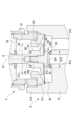
- FIG. 1 is a cross-sectional view of a fluid control valve according to an embodiment of the present invention.
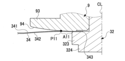
- FIG. 2 is a partially enlarged view of a portion A in FIG.
- FIG. 2 is a perspective view of a diaphragm member.
- 5A and 5B are diagrams illustrating the state of a diaphragm member when the fluid control valve according to the embodiment is in an open state.
- 11A and 11B are diagrams illustrating deformation of a diaphragm member immediately after a valve element of the fluid control valve according to the present embodiment starts to move in a contact direction.
- 5A and 5B are diagrams illustrating deformation of a diaphragm member when the fluid control valve according to the embodiment is in a valve closed state.
- FIG. 1 is a cross-sectional view of a fluid control valve invented by the present inventor as a solution to the problem of a decrease in the self-returning force of a diaphragm member at high temperatures.
- 6 is a diagram showing a state of a diaphragm member when the fluid control valve shown in FIG. 5 is in a valve open state.
- 6 is a diagram showing a state of deformation of a diaphragm member immediately after a valve body of the fluid control valve shown in FIG. 5 starts to move in a contact direction.
- 6 is a diagram showing deformation of a diaphragm member when the fluid control valve shown in FIG. 5 is in a valve closed state.
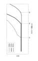
- FIG. 10 is a graph showing the relationship between the amount of movement of the valve disc in the abutment direction from a position in a valve open state and the stress generated in a diaphragm member.
- 4 is a graph showing the relationship between the stroke amount and the Cv value when the valve disc is at a high temperature.
- Fig. 1 is a cross-sectional view of the fluid control valve 1 according to this embodiment.
- Fig. 2 is a partially enlarged view of a portion A in Fig. 1.
- Fig. 3 is a perspective view of a diaphragm member 34.
- the fluid control valve 1 is a pneumatically driven gas valve that is arranged in the gas supply system of a semiconductor manufacturing device, and as shown in FIG. 1, it is made up of a drive unit 2 and a valve unit 3.
- the drive unit 2 further comprises an actuator unit 4 and a spring unit 5.
- the actuator unit 4 includes a pneumatically driven air cylinder 6 and a connection bracket 7 for connecting the air cylinder 6 and the spring unit 5.
- the air cylinder 6 comprises a cylindrical case 61, a piston (not shown) loaded inside the case 61, and a cylindrical drive shaft (not shown) connected to the piston.
- the piston is able to slide in the vertical direction in FIG. 1 inside the case 61, and the drive shaft advances and retreats along its axial direction as the piston moves up and down.
- the axial direction of the drive shaft is parallel to the vertical direction in FIG. 1 and coincides with the direction in which the valve body 32, described later, moves in contact with and away from the valve seat 33. Note that the upper side in the figure is the moving away direction, and the lower side is the contact direction.
- the tip of the drive shaft of the air cylinder 6 on the valve section 3 side protrudes from the case 61 and is connected to a cylindrical operating rod 9 that is positioned coaxially with the drive shaft. Therefore, as the drive shaft of the air cylinder 6 moves back and forth, the operating rod 9 also moves back and forth along its axis CL (see Figure 2).
- the operating rod 9 is inserted through the spring portion 5 and extends from inside the connection bracket 7 to the valve portion 3. As shown in FIG. 2, the operating rod 9 has an enlarged diameter portion 91 at the portion inserted into the valve portion 3, which has a larger diameter than the portion inserted into the connection bracket 7 and the portion inserted into the spring portion 5, thereby forming a step portion 92. Furthermore, the operating rod 9 has a first clamping piece 93 at the end opposite the step portion 92 of the enlarged diameter portion 91. The first clamping piece 93 is used to clamp the diaphragm member 34 described later together with a second clamping piece 323 described later.
- the first clamping piece 93 has a circular shape with a radial direction perpendicular to the axis CL of the operating rod 9, and is located coaxially with the axis CL.
- the diameter D11 of the first clamping piece 93 is larger than the diameter of the enlarged diameter portion 91.
- the surface of the first clamping piece 93 facing the diaphragm member 34 is a convex spherical surface 94 that bulges toward the diaphragm member 34.
- the center of the convex spherical surface 94 is located on the axis CL of the operating rod 9, and the radius (first radius) is set to, for example, about 70 mm.
- the outer periphery of the convex spherical surface 94 is also chamfered.
- a female thread 95 is drilled into the end face of the operating rod 9 on the valve section 3 side, allowing the valve body 32, which will be described later, to be screwed into it.
- the spring section 5 is provided with a compression coil spring 52 located coaxially with the operating rod 9 in the internal space 51.
- the compression coil spring 52 is compressed by the end face 53 on the actuator section 4 side of the internal space 51 and the step section 92 of the operating rod 9. Therefore, the compression coil spring 52 always biases the operating rod 9 in the contact direction (downward in the figure).
- the valve portion 3 includes a body 31, a valve element 32, a valve seat 33, and a diaphragm member 34.
- the body 31 includes a cylindrical portion 315 that connects to the spring portion 5.
- the body 31 also includes a valve chamber 311 drilled inside the cylindrical portion 315.
- the valve chamber 311 communicates with an input flow path 313 through a valve port 312 at the center of the bottom. This input flow path 313 is used to input process gas into the valve chamber 311.
- a circular valve seat 33 is fixed to the bottom surface of the valve chamber 311 on the outer periphery of the valve port 312 and coaxially with the valve port 312.
- the valve seat 33 is made of a material such as PI (polyimide) or PFA (tetrafluoroethylene-perfluoroalkylvinylether copolymer), which has excellent heat resistance.
- the valve chamber 311 communicates with an output flow path 314 on the radial outside of the valve seat 33. This output flow path 314 is used to output the process gas from the valve chamber 311.
- the valve body 32 is made of, for example, stainless steel.
- the valve body 32 has a cylindrical main body 321, and further has a male threaded portion 322 on the operating rod 9 side of the main body 321.
- the valve body 32 is connected to the operating rod 9 by screwing the male threaded portion 322 into the female threaded portion 95 of the operating rod 9.
- the valve body 32 also has a second clamping piece 323 on the side opposite the male threaded portion 322 of the main body 321.
- the second clamping piece 323 is circular with a radial direction perpendicular to the axis CL of the operating rod 9, and is positioned coaxially with the axis CL.
- the diameter D12 of the second clamping piece 323 is smaller than the diameter D11 of the first clamping piece 93.
- the valve body 32 also has an abutment portion 324 that abuts against and separates from the valve seat 33 on the side opposite the main body portion 321 of the second clamping piece 323.
- This abutment portion 324 is also circular and positioned coaxially with the axis CL of the operating rod 9. Because the valve body 32 is connected to the operating rod 9, the abutment portion 324 abuts against and separates from the valve seat 33 in the direction of the axis CL as the operating rod 9 moves forward and backward.
- the diaphragm member 34 is made of, for example, a Ni alloy.
- the center of the diaphragm member 34 is located on an extension of the axis CL, and the diaphragm member 34 is formed in a spherical crown shape that bulges toward the operating rod 9. Therefore, the facing surface 341 that faces the convex spherical surface 94 of the diaphragm member 34 is a spherical surface.
- the radius (second radius) of the sphere of the facing surface 341 is set to, for example, about 140 mm.
- the surface on the back side of the facing surface 341 is called the back surface 342.
- a cut 343 is provided at the apex of the diaphragm member 34 (facing surface 341).
- This cut 343 is circular in shape with the radial direction perpendicular to the axis CL, and is located coaxially with the axis CL.
- the outer periphery of the facing surface 341 is provided with a flat edge 344 perpendicular to the axis CL.
- This edge 344 is circular in shape with the radial direction perpendicular to the axis CL.
- the diaphragm member 34 as described above is fixed inside the fluid control valve 1 as follows.
- the male threaded portion 322 of the valve body 32 is inserted into the cut 343 of the diaphragm member 34 from the side opposite to the opposing surface 341, and the diaphragm member 34 and the valve body 32 are positioned so that they are coaxially positioned with the back surface 342 of the diaphragm member 34 in contact with the second clamping piece 323 of the valve body 32.
- the male threaded portion 322 is screwed into the female threaded portion 95 of the operating rod 9 until the convex spherical surface 94 of the first clamping piece 93 comes into contact with the spherical surface 341 of the diaphragm member 34.
- the diaphragm member 34 is clamped from both sides at the edge of the cut 343 by the first clamping piece 93 and the second clamping piece 323 in the direction of the axis CL (the up and down direction in the figure), as shown in FIG. 1 or FIG. 2. That is, the operating rod 9 and the diaphragm member 34 are connected. Furthermore, as shown in FIG. 1 or FIG. 2, the edge portion 344 of the diaphragm member 34 is clamped and fixed from above and below within the valve portion 3.
- the inside of the cylindrical portion 315 of the body 31 is divided into the valve chamber 311 and its upper portion, and is designed to repeatedly elastically deform as the valve body 32 moves in the direction of contact and separation.
- Figure 4A is a diagram showing the state of the diaphragm member 34 when the fluid control valve 1 according to this embodiment is in the valve open state.
- Figure 4B is a diagram showing the state of deformation of the diaphragm member 34 immediately after the valve body 32 of the fluid control valve 1 according to this embodiment starts to move in the abutment direction.
- Figure 4C is a diagram showing the state of deformation of the diaphragm member 34 when the fluid control valve 1 according to this embodiment is in the valve closed state.
- the diaphragm member 34 deforms along the shape of the convex spherical surface 94, so the contact area A11 between the convex spherical surface 94 of the first clamping piece 93 and the opposing surface 341 of the diaphragm member 34 expands from the center toward the outer periphery as the valve body 32 approaches the valve seat 33 ( Figures 4B and 4C).
- the inventors of the present application have confirmed through finite element analysis that the location where stress concentrates when the diaphragm member 34 deforms as described above is the outermost periphery P11 of the contact range A11. In other words, when switching from the open valve state to the closed valve state, the location where stress concentrates on the diaphragm member 34 moves in accordance with the fluctuation of the contact range A11 and is not constant, so the diaphragm member 34 is less likely to be damaged even if the valve body 32 is repeatedly moved in and out of contact.
- the diaphragm member 34 By making the diaphragm member 34 less likely to be damaged in this way, it is possible to increase the distance (stroke amount) between the position of the valve body 32 in the open valve state and the position of the valve body 32 in the closed valve state compared to the conventional method. If the stroke amount can be increased, the distance between the valve body 32 and the valve seat 33 becomes larger in the open valve state, and the Cv value of the fluid control valve 1 becomes larger.
- the radius of the convex spherical surface 94 is 50% to 65% of the radius of the spherical surface 341.
- the radius (first radius) of the convex spherical surface 94 is approximately 70 mm, while the radius (second radius) of the opposing surface 341 of the diaphragm member 34 is approximately 140 mm.
- the diameter D11 of the first clamping piece 93 is a value that exceeds 35% of the diameter D21 (see FIG. 3) of the diaphragm member 34.
- the diameter D21 of the diaphragm member 34 is the diameter when the diaphragm member 34 is projected onto a plane perpendicular to the axis CL of the operating rod 9, that is, the diameter of the edge portion 344 in this embodiment.
- Figure 7 is a graph showing the relationship between the amount of movement (stroke amount) of the valve body 32 in the abutment direction from the position in the valve open state (hereinafter referred to as the valve open position) and the stress generated in the diaphragm member, and compares the case where the diameter D11 of the first clamping piece 93 is 35% of the diameter D21 of the diaphragm member 34, the case where it is 65% of the diameter D21, and the case where it is 85% of the diameter D21.
- the waveform shown by the dashed dotted line in Figure 7 is the waveform when the diameter D11 is 35% of the diameter D21.
- the diameter D11 is 35% of the diameter D21 is the same as the relationship between the diameter of the clamping part 111 and the diameter of the diaphragm member 34 in the fluid control valve 100 shown in Figure 5.
- the waveform shown by the solid line in Figure 7 is the waveform when the diameter D11 is 65% of the diameter D21.
- the dashed waveform in Figure 7 is the waveform when diameter D11 is 85% of diameter D21.
- the rising parts of each waveform indicate the occurrence of stress concentration to the extent that the diaphragm member 34 is broken.
- Figure 8 is a graph showing the relationship between the stroke amount and Cv value when the valve body 32 is at a high temperature. It shows that the Cv value increases as the stroke amount increases.
- the diameter D11 of the first clamping piece 93 is approximately 65% of the diameter D21 of the diaphragm member 34, a waveform rise can be seen when the amount of movement of the valve body 32 reaches S2 (see FIG. 7).
- S2 the amount of movement of the valve body 32 reaches S2
- a stress concentration occurs to the extent that the diaphragm member 34 is broken. Therefore, a stroke amount of S2 can be ensured at most.
- This stroke amount is approximately 1.8 times the stroke amount when the diameter D11 is 35% of the diameter D21.
- the Cv value of the fluid control valve 1 when the stroke amount is S2 is C2 (see FIG. 8). This is approximately 1.5 times the Cv value when the diameter D11 is 35% of the diameter D21.
- the diameter D11 of the first clamping piece 93 is approximately 85% of the diameter D21 of the diaphragm member 34, a rise in the waveform can be seen when the amount of movement of the valve body 32 reaches S3 (see FIG. 7).
- S3 the amount of movement of the valve body 32 reaches S3
- This stroke amount is approximately 2.5 times the stroke amount when the diameter D11 is 35% of the diameter D21.
- the Cv value of the fluid control valve 1 when the stroke amount is S3 is C3 (see FIG. 8). This is approximately 1.65 times the Cv value when the diameter D11 is 35% of the diameter D21.
- the diameter D11 of the first clamping piece 93 is a value that exceeds 35% of the diameter D21 of the diaphragm member 34, as shown in FIG. 7, it is possible to delay the rise of the waveform more than when the diameter D11 is 35% of the diameter D21. In other words, it is possible to move the valve body 32 more, that is, to increase the stroke amount. It is desirable that the diameter D11 of the first clamping piece 93 be as large as the structure of the fluid control valve 1 allows, but in reality it will be smaller than the diameter D21 of the diaphragm member 34.
- the fluid control valve 1 includes (1) an operating rod 9, a valve body 32 connected to the operating rod 9, a valve seat 33 against which the valve body 32 comes into contact and separates, and a diaphragm member 34 located between the operating rod 9 and the valve body 32.
- the diaphragm member 34 is formed in a spherical crown shape whose center is located on an extension of the axis CL and which bulges out towards the operating rod 9, and its apex (cut 343) is in contact with the axis of the operating rod 9.
- first clamping piece 93 that contacts the diaphragm member 34 from the side of the valve body 32 and a second clamping piece 323 that contacts the diaphragm member 34 from the side of the valve body 32
- first clamping piece 93 and the second clamping piece 323 are formed in a circular shape positioned coaxially with the operating rod 9
- the diameter D11 of the first clamping piece 93 is larger than the diameter D of the second clamping piece 323
- the surface of the first clamping piece 93 facing the diaphragm member 34 is formed to bulge toward the diaphragm member 34 and is a convex spherical surface 94 with its center on the axis CL of the operating rod 9.
- the first radius which is the radius of the convex spherical surface 94
- the second radius which is the radius of the spherical surface (opposing surface 341) facing the convex spherical surface 94 of the diaphragm member 34.
- the first radius is 50% or more and 65% or less of the second radius.
- the diameter D11 of the first clamping piece 93 is a value that exceeds 35% of the diameter D21 when projected onto a plane perpendicular to the axis CL of the diaphragm member 34.
- the diaphragm member 34 when the valve body 32 is brought into contact with the valve seat 33, the diaphragm member 34 is deformed by being pushed down from the apex portion clamped by the first clamping piece 93 and the second clamping piece 323 toward the valve seat 33. During this deformation, the diaphragm member 34 deforms along the shape of the convex spherical surface 94 of the first clamping piece 93, so that the contact area A11 between the convex spherical surface 94 and the diaphragm member 34 expands from the center of the diaphragm member 34 toward the outer periphery as the valve body 32 approaches the valve seat 33.
- the inventors of the present application have confirmed through finite element analysis that the location where stress is concentrated in the diaphragm member 34 is the outermost periphery P11 of the contact area A11.
- the point where stress is concentrated in the diaphragm member 34 moves in accordance with the fluctuation of the contact range A11 and is not constant, so the diaphragm member 34 is less likely to be damaged even if the valve body 32 is repeatedly moved in and out of contact.
- the diaphragm member 34 By making the diaphragm member 34 less likely to be damaged in this way, it is possible to increase the distance (stroke amount) between the position of the valve body 32 in the open state and the position of the valve body 32 in the closed state more than before. If the stroke amount can be increased, the distance between the valve body 32 and the valve seat 33 becomes larger in the open state, and the Cv value of the fluid control valve 1 becomes larger.
- the drive unit 2 of the fluid control valve 1 uses an air cylinder 6 driven by air pressure as a drive source, but other drive sources such as an electric linear motor may be used.
- the first clamping piece 93 and the operating rod 9 are integrally formed as the same member, but the first clamping piece and the operating rod 9 may be separate members.
- the second clamping piece 323 and the valve body 32 are integrally formed as the same member, but the second clamping piece 323 and the valve body 32 may be separate members.
Landscapes
- Engineering & Computer Science (AREA)
- General Engineering & Computer Science (AREA)
- Mechanical Engineering (AREA)
- Fluid-Driven Valves (AREA)
- Lift Valve (AREA)
Abstract
Description
本実施形態に係る流体制御弁1の構成について図面を用いて説明する。図1は、本実施形態に係る流体制御弁1の断面図である。図2は、図1の部分Aの部分拡大図である。図3は、ダイアフラム部材34の斜視図である。
流体制御弁1を弁開状態から弁閉状態とする動作について説明する。エアシリンダ6に対して操作エアの送給をすると、図1に示すように、流体制御弁1は弁開状態となる。上述の通り、操作ロッド9が常に圧縮コイルばね52に当接方向に付勢されているため、弁開状態とは、アクチュエータ部4が圧縮コイルばね52の付勢力に抗して、操作ロッド9を図中の上方に引き上げている状態である。この状態から弁閉状態とするには、エアシリンダ6に対する操作エアの送給を停止する。すると、圧縮コイルばね52の付勢力により、操作ロッド9および弁体32が弁座33の側に押し下げられ、弁体32の当接部324が弁座33に当接される。
9 操作ロッド
32 弁体
33 弁座
34 ダイアフラム部材
93 第1挟持片
94 凸球面
323 第2挟持片
Claims (4)
- 操作ロッドと、前記操作ロッドに連結される弁体と、前記弁体が当接離間をする弁座と、前記操作ロッドと前記弁体の間に位置するダイアフラム部材と、を備え、前記操作ロッドにより駆動される前記弁体が、前記操作ロッドの軸心の方向に沿って前記当接離間を行うことで、制御流体の制御を行う流体制御弁において、
前記ダイアフラム部材は、中心が前記軸心の延長線上に位置し、かつ、前記操作ロッドの側に膨出する球冠状に形成され、その頂点部で、前記操作ロッドの側から前記ダイアフラム部材に接する第1挟持片と、前記弁体の側から前記ダイアフラム部材に接する第2挟持片と、により前記軸心と平行な方向において両側から挟持されていること、
前記第1挟持片と前記第2挟持片とは、前記操作ロッドと同軸に位置する円形状に形成され、前記第1挟持片の直径は、前記第2挟持片の直径より大きいこと、
前記第1挟持片の、前記ダイアフラム部材に対向する面は、前記ダイアフラム部材の側に膨出して形成され、かつ、前記軸心上に中心を有する凸球面であること、
を特徴とする流体制御弁。 - 請求項1に記載の流体制御弁において、
前記凸球面の半径である第1半径は、前記ダイアフラム部材の前記凸球面に対向する球面の半径である第2半径よりも小さいこと、
を特徴とする流体制御弁。 - 請求項2に記載の流体制御弁において、
前記第1半径は、前記第2半径の50%以上65%以下であること、
を特徴とする流体制御弁。 - 請求項1乃至3のいずれか1つに記載の流体制御弁において、
前記第1挟持片の直径は、前記ダイアフラム部材の前記軸心に直交する平面に投影した場合の直径の35%を超える値であること、
を特徴とする流体制御弁。
Priority Applications (2)
| Application Number | Priority Date | Filing Date | Title |
|---|---|---|---|
| KR1020257026885A KR20250134128A (ko) | 2023-06-28 | 2024-03-21 | 유체 제어 밸브 |
| CN202480011909.9A CN120677326A (zh) | 2023-06-28 | 2024-03-21 | 流体控制阀 |
Applications Claiming Priority (2)
| Application Number | Priority Date | Filing Date | Title |
|---|---|---|---|
| JP2023105753A JP2025005544A (ja) | 2023-06-28 | 2023-06-28 | 流体制御弁 |
| JP2023-105753 | 2023-06-28 |
Publications (1)
| Publication Number | Publication Date |
|---|---|
| WO2025004469A1 true WO2025004469A1 (ja) | 2025-01-02 |
Family
ID=93938523
Family Applications (1)
| Application Number | Title | Priority Date | Filing Date |
|---|---|---|---|
| PCT/JP2024/010962 Ceased WO2025004469A1 (ja) | 2023-06-28 | 2024-03-21 | 流体制御弁 |
Country Status (4)
| Country | Link |
|---|---|
| JP (1) | JP2025005544A (ja) |
| KR (1) | KR20250134128A (ja) |
| CN (1) | CN120677326A (ja) |
| WO (1) | WO2025004469A1 (ja) |
Citations (4)
| Publication number | Priority date | Publication date | Assignee | Title |
|---|---|---|---|---|
| JPS6293468U (ja) * | 1985-12-04 | 1987-06-15 | ||
| JPH11173429A (ja) * | 1997-12-10 | 1999-06-29 | Fujikin Inc | 金属ダイヤフラム型バルブ |
| US20050109973A1 (en) * | 2003-11-21 | 2005-05-26 | Glime William H. | Valve diaphragm |
| JP2020015946A (ja) * | 2018-07-25 | 2020-01-30 | 株式会社ジャパンディスプレイ | マスクユニットの製造装置 |
Family Cites Families (3)
| Publication number | Priority date | Publication date | Assignee | Title |
|---|---|---|---|---|
| JP6564593B2 (ja) | 2015-03-25 | 2019-08-21 | 株式会社フジキン | ダイヤフラム弁 |
| JP6307557B2 (ja) | 2016-06-17 | 2018-04-04 | Ckd株式会社 | 流体制御弁 |
| JP7328775B2 (ja) * | 2019-03-26 | 2023-08-17 | 株式会社キッツエスシーティー | ダイヤフラムバルブ |
-
2023
- 2023-06-28 JP JP2023105753A patent/JP2025005544A/ja active Pending
-
2024
- 2024-03-21 WO PCT/JP2024/010962 patent/WO2025004469A1/ja not_active Ceased
- 2024-03-21 CN CN202480011909.9A patent/CN120677326A/zh active Pending
- 2024-03-21 KR KR1020257026885A patent/KR20250134128A/ko active Pending
Patent Citations (4)
| Publication number | Priority date | Publication date | Assignee | Title |
|---|---|---|---|---|
| JPS6293468U (ja) * | 1985-12-04 | 1987-06-15 | ||
| JPH11173429A (ja) * | 1997-12-10 | 1999-06-29 | Fujikin Inc | 金属ダイヤフラム型バルブ |
| US20050109973A1 (en) * | 2003-11-21 | 2005-05-26 | Glime William H. | Valve diaphragm |
| JP2020015946A (ja) * | 2018-07-25 | 2020-01-30 | 株式会社ジャパンディスプレイ | マスクユニットの製造装置 |
Also Published As
| Publication number | Publication date |
|---|---|
| KR20250134128A (ko) | 2025-09-09 |
| JP2025005544A (ja) | 2025-01-17 |
| CN120677326A (zh) | 2025-09-19 |
Similar Documents
| Publication | Publication Date | Title |
|---|---|---|
| US8602052B2 (en) | Clamp ring for welded diaphragms | |
| JP6307557B2 (ja) | 流体制御弁 | |
| TW201812197A (zh) | 流體控制閥以及流體控制閥製造方法 | |
| CN106164549B (zh) | 流体控制器 | |
| CN114667424B (zh) | 动力元件以及使用了该动力元件的膨胀阀 | |
| JP7624762B2 (ja) | パワーエレメント及びこれを用いた膨張弁 | |
| JP2025005544A (ja) | 流体制御弁 | |
| CN114667422A (zh) | 动力元件以及使用了该动力元件的膨胀阀 | |
| US20180355983A1 (en) | Diaphragm valve | |
| CN104781595B (zh) | 阀结构 | |
| JP2025121681A (ja) | 流体制御弁 | |
| JP7863533B2 (ja) | 流体制御弁 | |
| US12578024B2 (en) | Fluid control valve | |
| KR102039067B1 (ko) | 극저온 밸브 장치 | |
| JP7792731B2 (ja) | 電磁弁及び電磁弁の組立方法 | |
| JP7859655B2 (ja) | ダイヤフラムバルブ | |
| CN112780780B (zh) | 阀装置 | |
| JP2026009695A (ja) | バルブ | |
| JP2011027192A (ja) | 開閉弁 | |
| JP4641190B2 (ja) | 可変容量型圧縮機用制御弁 | |
| JP2006220231A (ja) | ダイアフラムバルブ | |
| JP2024065482A (ja) | バルブ装置 | |
| JP2024094719A (ja) | 高温用バルブアクチュエータおよび高温用ダイヤフラムバルブ | |
| CN107143676A (zh) | 容量调整阀 | |
| JP2025157768A (ja) | 流体制御弁 |
Legal Events
| Date | Code | Title | Description |
|---|---|---|---|
| 121 | Ep: the epo has been informed by wipo that ep was designated in this application |
Ref document number: 24831346 Country of ref document: EP Kind code of ref document: A1 |
|
| WWE | Wipo information: entry into national phase |
Ref document number: 202480011909.9 Country of ref document: CN |
|
| ENP | Entry into the national phase |
Ref document number: 1020257026885 Country of ref document: KR Free format text: ST27 STATUS EVENT CODE: A-0-1-A10-A15-NAP-PA0105 (AS PROVIDED BY THE NATIONAL OFFICE) |
|
| WWE | Wipo information: entry into national phase |
Ref document number: 1020257026885 Country of ref document: KR |
|
| WWP | Wipo information: published in national office |
Ref document number: 202480011909.9 Country of ref document: CN |
|
| NENP | Non-entry into the national phase |
Ref country code: DE |