WO2025004445A1 - 角形鋼管およびその製造方法ならびに建築構造物 - Google Patents
角形鋼管およびその製造方法ならびに建築構造物 Download PDFInfo
- Publication number
- WO2025004445A1 WO2025004445A1 PCT/JP2024/006688 JP2024006688W WO2025004445A1 WO 2025004445 A1 WO2025004445 A1 WO 2025004445A1 JP 2024006688 W JP2024006688 W JP 2024006688W WO 2025004445 A1 WO2025004445 A1 WO 2025004445A1
- Authority
- WO
- WIPO (PCT)
- Prior art keywords
- less
- steel
- steel pipe
- temperature
- pearlite
- Prior art date
- Legal status (The legal status is an assumption and is not a legal conclusion. Google has not performed a legal analysis and makes no representation as to the accuracy of the status listed.)
- Ceased
Links
Images


Classifications
-
- C—CHEMISTRY; METALLURGY
- C22—METALLURGY; FERROUS OR NON-FERROUS ALLOYS; TREATMENT OF ALLOYS OR NON-FERROUS METALS
- C22C—ALLOYS
- C22C38/00—Ferrous alloys, e.g. steel alloys
- C22C38/04—Ferrous alloys, e.g. steel alloys containing manganese
-
- B—PERFORMING OPERATIONS; TRANSPORTING
- B21—MECHANICAL METAL-WORKING WITHOUT ESSENTIALLY REMOVING MATERIAL; PUNCHING METAL
- B21C—MANUFACTURE OF METAL SHEETS, WIRE, RODS, TUBES, PROFILES OR LIKE SEMI-MANUFACTURED PRODUCTS OTHERWISE THAN BY ROLLING; AUXILIARY OPERATIONS USED IN CONNECTION WITH METAL-WORKING WITHOUT ESSENTIALLY REMOVING MATERIAL
- B21C37/00—Manufacture of metal sheets, rods, wire, tubes, profiles or like semi-manufactured products, not otherwise provided for; Manufacture of tubes of special shape
- B21C37/06—Manufacture of metal sheets, rods, wire, tubes, profiles or like semi-manufactured products, not otherwise provided for; Manufacture of tubes of special shape of tubes or metal hoses; Combined procedures for making tubes, e.g. for making multi-wall tubes
- B21C37/08—Making tubes with welded or soldered seams
- B21C37/0803—Making tubes with welded or soldered seams the tubes having a special shape, e.g. polygonal tubes
-
- B—PERFORMING OPERATIONS; TRANSPORTING
- B21—MECHANICAL METAL-WORKING WITHOUT ESSENTIALLY REMOVING MATERIAL; PUNCHING METAL
- B21C—MANUFACTURE OF METAL SHEETS, WIRE, RODS, TUBES, PROFILES OR LIKE SEMI-MANUFACTURED PRODUCTS OTHERWISE THAN BY ROLLING; AUXILIARY OPERATIONS USED IN CONNECTION WITH METAL-WORKING WITHOUT ESSENTIALLY REMOVING MATERIAL
- B21C37/00—Manufacture of metal sheets, rods, wire, tubes, profiles or like semi-manufactured products, not otherwise provided for; Manufacture of tubes of special shape
- B21C37/06—Manufacture of metal sheets, rods, wire, tubes, profiles or like semi-manufactured products, not otherwise provided for; Manufacture of tubes of special shape of tubes or metal hoses; Combined procedures for making tubes, e.g. for making multi-wall tubes
- B21C37/15—Making tubes of special shape; Making tube fittings
-
- C—CHEMISTRY; METALLURGY
- C21—METALLURGY OF IRON
- C21D—MODIFYING THE PHYSICAL STRUCTURE OF FERROUS METALS; GENERAL DEVICES FOR HEAT TREATMENT OF FERROUS OR NON-FERROUS METALS OR ALLOYS; MAKING METAL MALLEABLE, e.g. BY DECARBURISATION OR TEMPERING
- C21D8/00—Modifying the physical properties of ferrous metals or ferrous alloys by deformation combined with, or followed by, heat treatment
- C21D8/02—Modifying the physical properties of ferrous metals or ferrous alloys by deformation combined with, or followed by, heat treatment during manufacturing of plates or strips
- C21D8/0221—Modifying the physical properties of ferrous metals or ferrous alloys by deformation combined with, or followed by, heat treatment during manufacturing of plates or strips characterised by the working steps
- C21D8/0226—Hot rolling
-
- C—CHEMISTRY; METALLURGY
- C21—METALLURGY OF IRON
- C21D—MODIFYING THE PHYSICAL STRUCTURE OF FERROUS METALS; GENERAL DEVICES FOR HEAT TREATMENT OF FERROUS OR NON-FERROUS METALS OR ALLOYS; MAKING METAL MALLEABLE, e.g. BY DECARBURISATION OR TEMPERING
- C21D8/00—Modifying the physical properties of ferrous metals or ferrous alloys by deformation combined with, or followed by, heat treatment
- C21D8/02—Modifying the physical properties of ferrous metals or ferrous alloys by deformation combined with, or followed by, heat treatment during manufacturing of plates or strips
- C21D8/0247—Modifying the physical properties of ferrous metals or ferrous alloys by deformation combined with, or followed by, heat treatment during manufacturing of plates or strips characterised by the heat treatment
- C21D8/0263—Modifying the physical properties of ferrous metals or ferrous alloys by deformation combined with, or followed by, heat treatment during manufacturing of plates or strips characterised by the heat treatment following hot rolling
-
- C—CHEMISTRY; METALLURGY
- C21—METALLURGY OF IRON
- C21D—MODIFYING THE PHYSICAL STRUCTURE OF FERROUS METALS; GENERAL DEVICES FOR HEAT TREATMENT OF FERROUS OR NON-FERROUS METALS OR ALLOYS; MAKING METAL MALLEABLE, e.g. BY DECARBURISATION OR TEMPERING
- C21D8/00—Modifying the physical properties of ferrous metals or ferrous alloys by deformation combined with, or followed by, heat treatment
- C21D8/10—Modifying the physical properties of ferrous metals or ferrous alloys by deformation combined with, or followed by, heat treatment during manufacturing of tubular bodies
-
- C—CHEMISTRY; METALLURGY
- C22—METALLURGY; FERROUS OR NON-FERROUS ALLOYS; TREATMENT OF ALLOYS OR NON-FERROUS METALS
- C22C—ALLOYS
- C22C38/00—Ferrous alloys, e.g. steel alloys
-
- C—CHEMISTRY; METALLURGY
- C22—METALLURGY; FERROUS OR NON-FERROUS ALLOYS; TREATMENT OF ALLOYS OR NON-FERROUS METALS
- C22C—ALLOYS
- C22C38/00—Ferrous alloys, e.g. steel alloys
- C22C38/02—Ferrous alloys, e.g. steel alloys containing silicon
-
- C—CHEMISTRY; METALLURGY
- C22—METALLURGY; FERROUS OR NON-FERROUS ALLOYS; TREATMENT OF ALLOYS OR NON-FERROUS METALS
- C22C—ALLOYS
- C22C38/00—Ferrous alloys, e.g. steel alloys
- C22C38/06—Ferrous alloys, e.g. steel alloys containing aluminium
-
- C—CHEMISTRY; METALLURGY
- C22—METALLURGY; FERROUS OR NON-FERROUS ALLOYS; TREATMENT OF ALLOYS OR NON-FERROUS METALS
- C22C—ALLOYS
- C22C38/00—Ferrous alloys, e.g. steel alloys
- C22C38/60—Ferrous alloys, e.g. steel alloys containing lead, selenium, tellurium, or antimony, or more than 0.04% by weight of sulfur
-
- C—CHEMISTRY; METALLURGY
- C21—METALLURGY OF IRON
- C21D—MODIFYING THE PHYSICAL STRUCTURE OF FERROUS METALS; GENERAL DEVICES FOR HEAT TREATMENT OF FERROUS OR NON-FERROUS METALS OR ALLOYS; MAKING METAL MALLEABLE, e.g. BY DECARBURISATION OR TEMPERING
- C21D2211/00—Microstructure comprising significant phases
- C21D2211/002—Bainite
-
- C—CHEMISTRY; METALLURGY
- C21—METALLURGY OF IRON
- C21D—MODIFYING THE PHYSICAL STRUCTURE OF FERROUS METALS; GENERAL DEVICES FOR HEAT TREATMENT OF FERROUS OR NON-FERROUS METALS OR ALLOYS; MAKING METAL MALLEABLE, e.g. BY DECARBURISATION OR TEMPERING
- C21D2211/00—Microstructure comprising significant phases
- C21D2211/005—Ferrite
-
- C—CHEMISTRY; METALLURGY
- C21—METALLURGY OF IRON
- C21D—MODIFYING THE PHYSICAL STRUCTURE OF FERROUS METALS; GENERAL DEVICES FOR HEAT TREATMENT OF FERROUS OR NON-FERROUS METALS OR ALLOYS; MAKING METAL MALLEABLE, e.g. BY DECARBURISATION OR TEMPERING
- C21D2211/00—Microstructure comprising significant phases
- C21D2211/009—Pearlite
Definitions
- the present invention relates to a square steel pipe and its manufacturing method, and to an architectural structure, and in particular to a square steel pipe (square column) manufactured by cold roll forming, which has a low yield ratio, excellent low-temperature toughness, and high ductility.
- the present invention relates to a square steel pipe that is suitable for use as an architectural structural member for large buildings.
- the present invention further relates to an architectural structure obtained by using this square steel pipe.
- Square steel pipes are generally manufactured by cold forming hot-rolled steel sheets (hot-rolled steel strips) or thick steel plates.
- Cold forming methods include cold press bending and cold roll forming.
- Square steel pipes (hereinafter sometimes referred to as roll-formed square steel pipes) are manufactured by cold-rolling hot-rolled steel plate to form a cylindrical open pipe, and then electric resistance welding is performed on the butt joint to form a round steel pipe.
- the round steel pipe is then drawn by a few percent in the axial direction by rolls placed above, below, left and right of the round steel pipe, and then formed into a square shape to produce a square steel pipe.
- square steel pipes (hereinafter sometimes referred to as press-formed square steel pipes) are manufactured by press-bending the raw material, and thick steel plate is press-bended in the cold to form a square or U-shaped cross-sectional shape. These are then joined by submerged arc welding to produce the pipes.
- the manufacturing method of roll-formed square steel pipes has the advantage of being more productive and capable of being manufactured in a short period of time compared to the manufacturing method of press-formed square steel pipes.
- press-formed square steel pipes the flat parts are not cold-formed and only the corners are work-hardened, whereas in roll-formed square steel pipes, large processing strain is introduced in the axial direction around the entire circumference of the steel pipe, especially when cold-forming into a cylindrical shape. Due to this processing strain, roll-formed square steel pipes have the problem that the yield ratio in the axial direction is high even in the flat parts, and toughness is low.
- the corners have a higher yield ratio and lower toughness than the flat parts because the processing strain introduced is greater in the corners than in the flat parts.
- Patent Document 1 proposes a technology for manufacturing square steel pipes with a yield ratio of 90% or less and a Charpy absorbed energy of 27 J or more at a test temperature of 0°C by hot rolling a steel material containing, by weight, 0.20% or less C and one or two of 0.40-0.90% Mn, 0.005-0.040% Nb, and 0.005-0.050% into a coil through a hot rolling process with a reduction rate of 55% or more in the non-recrystallization temperature range, a rolling end temperature of 730-830°C, and a coiling temperature of 550°C or less, and by limiting the reduction in circumference in the steel pipe forming process to three times the plate thickness or less.
- Patent document 2 describes a method of heating steel containing, by mass, 0.07-0.18% C and 0.3-1.5% Mn to a heating temperature of 1100-1300°C, followed by rough rolling with a rough rolling end temperature of 1150-950°C, and finish rolling with a finish rolling start temperature of 1100-850°C and finish rolling end temperature of 900-750°C, followed by primary cooling in which the steel is cooled to a surface temperature with a cooling end temperature of 550°C or higher, and air cooling for 3-15 s.
- a technology has been proposed for manufacturing square steel pipes that have a low yield ratio of 80% or less and mechanical properties with an absorbed energy of 150 J or more in a Charpy impact test at a test temperature of 0°C by performing secondary cooling, followed by tertiary cooling, where the average cooling rate in the temperature range of 750 to 650°C at the center of the plate thickness is 4 to 15°C/s to 650°C or less, and by setting the value of the frequency of second phases contained in the steel structure to 0.20 to 0.42.
- Patent document 3 describes a method for producing a steel material containing, by mass%, 0.07-0.18% C and 0.3-1.5% Mn, which is heated to a temperature of 1100-1300°C, then subjected to rough rolling with a rough rolling end temperature of 1150-950°C and finish rolling with a finish rolling start temperature of 1100-850°C and finish rolling end temperature of 900-750°C, with the average cooling rate in the surface temperature range of 750-650°C being 20°C/s or less.
- a technology has been proposed to manufacture square steel pipes that have a low yield ratio of 80% or less and mechanical properties with an absorbed energy of 150 J or more in a Charpy impact test at a test temperature of 0°C by cooling to a coiling temperature of 500 to 650°C so that the time it takes for the temperature at the center of the plate thickness to reach 650°C is within 35 seconds and the average cooling rate in the temperature range of 750 to 650°C at the center of the plate thickness is 4 to 15°C/s.
- Patent Document 4 describes a method for heating a steel having a composition, by mass%, of C: 0.07-0.20%, Mn: 0.3-2.0%, P: 0.03% or less, S: 0.015% or less, Al: 0.01-0.06%, N: 0.006% or less, with the remainder being Fe and unavoidable impurities, to a heating temperature of 1100-1300°C, followed by rough rolling with a rough rolling end temperature of 1150-950°C, and finish rolling with a finish rolling start temperature of 1100-850°C and a finish rolling end temperature of 900-750°C, followed by cooling to a cooling end temperature of 580°C or less at a cooling rate such that the average cooling rate from the start of cooling to the end of cooling is 4-25°C/s at the center of the plate thickness, and then cooling is continued for 0.2 s in an initial cooling step, which is 10 s from the start of cooling.
- Patent Document 5 proposes a technology for manufacturing a square steel pipe by controlling the roll gap of the sizing stand immediately before square forming and the roll gap of the square forming stand so that, when a steel plate having a predetermined composition is formed into a square shape by cold roll forming, the ratio of the width W of the steel plate to the circumferential length C OUT of the square steel pipe at the outlet side of the square forming stand satisfies a predetermined formula, and the ratio of the circumferential length C IN of the electric resistance welded steel pipe at the inlet side of the square forming stand to the circumferential length C OUT of the square steel pipe at the outlet side of the square forming stand satisfies a predetermined formula.
- the uniform elongation E2 at a position 1/4t in the thickness direction from the outer surface of the corner is 0.60 times or more the uniform elongation E1 at a position 1/4t in the thickness direction from the outer surface of the flat plate, and the Charpy absorbed energy at -10°C at a position 1/4t from the outer surface of the corner has mechanical properties of 100 J or more.
- Square steel pipes manufactured using the technology described in Patent Document 4 have an absorbed energy of 27 J or more in a Charpy impact test at a test temperature of 0°C, and depending on the environment in which the square steel pipes are used, their low-temperature toughness may be insufficient.
- the present invention was made in consideration of the above problems, and aims to provide a square steel pipe that has a low yield ratio, excellent low-temperature toughness, and high ductility.
- the present invention also aims to provide a method for manufacturing the above-mentioned square steel pipe, and a building structure using the above-mentioned square steel pipe.
- the inventors have conducted extensive research to solve the above problems and to develop a square steel pipe that satisfies the strength (yield strength, tensile strength), yield ratio, ductility (uniform elongation, fracture elongation), and low-temperature toughness (absorbed energy and ductile-brittle transition temperature) that are the objectives of the present invention.
- the strength yield strength, tensile strength
- yield ratio yield ratio
- ductility uniform elongation, fracture elongation
- low-temperature toughness absorbed energy and ductile-brittle transition temperature
- the C content must be 0.07 mass% or more.
- the main phase of the steel structure in the center part of the plate thickness of the square steel pipe must be ferrite.
- the steel structure of the central portion of the thickness of the square steel pipe must have a second phase consisting of one or more types selected from pearlite, pseudo-pearlite, and upper bainite, and the area ratio of the second phase must be 5 to 30%.
- the steel structure must have an average crystal grain size of 10.0 to 30.0 ⁇ m, and a total of 500 pearlite and pseudo-pearlite particles with an equivalent circle diameter of 2 ⁇ m to 20 ⁇ m must be present at a rate of 500 particles/mm2 or more .
- the present invention has been completed based on these findings and comprises the following: [1] A square steel pipe having a flat portion and a corner portion,
- the steel composition is, in mass%, C: 0.07% or more and 0.20% or less, Si: 0.01% or more and 0.40% or less, Mn: 0.20% or more and 1.20% or less, P: 0.10% or less, S: 0.050% or less, Al: 0.005% or more and 0.100% or less, N: 0.010% or less, and the balance being Fe and unavoidable impurities;
- the steel structure of the plate thickness center portion of the flat plate portion has ferrite as a main phase, and the area ratio of a second phase consisting of one or more types selected from pearlite, pseudo-pearlite, and upper bainite is 5 to 30%, the average crystal grain size is 10.0 to 30.0 ⁇ m, and the steel structure contains pearlite and pseudo-pearlite having a circle equivalent diameter of 2 ⁇ m to 20 ⁇ m in a total of
- the steel composition further comprises, in mass%, Nb: 0.020% or less, Ti: 0.045% or less, V: 0.10% or less, Cr: 0.50% or less, Mo: 0.50% or less, Cu: 0.30% or less, Ni: 0.30% or less, Ca: 0.0100% or less, B: 0.0100% or less,
- the steel material having the above-mentioned steel composition is heated at a heating temperature of 1100°C or more and 1300°C or less for a heating time of 40 min or more and 200 min or less, and then subjected to hot rolling with a rough rolling end temperature of 850°C or more and 1150°C or less, a finish rolling end temperature of 750°C or more and 850°C or less, and 930°C or less, a total reduction ratio of 40% or more, and a total reduction ratio of the final two passes of finish rolling of 15% or more, and then Cooling is performed at an average cooling rate of 10.0 ° C./s or less at the center of the plate thickness, and a cooling stop temperature of 480 ° C.
- a method for manufacturing a square steel pipe comprising the steps of: forming the hot-rolled steel sheet into a cylindrical shape by roll forming; welding the ends of the hot-rolled steel sheet into a round steel pipe; and forming the hot-rolled steel sheet into a square steel pipe, wherein a compressive strain of 0.20 to 3.00% is imparted in the axial direction of the pipe after forming into the round steel pipe and/or after forming into the square steel pipe.
- the present invention provides a square steel pipe that has a low yield ratio, excellent low-temperature toughness, and high ductility.
- FIG. 1 is a perspective view showing a typical example of a building structure using the square steel pipe of the present invention.
- FIG. 2 is a schematic diagram showing the positions at which tensile test pieces were taken in the tensile test carried out in the present invention.
- FIG. 3 is a schematic diagram showing the positions at which Charpy test specimens were taken in the Charpy impact test carried out in the present invention.
- the square steel pipe of the present invention has a steel composition containing, by mass%, C: 0.07% to 0.20%, Si: 0.01% to 0.40%, Mn: 0.20% to 1.20%, P: 0.10% or less, S: 0.050% or less, Al: 0.005% to 0.100% or less, and N: 0.010% or less, with the balance being Fe and unavoidable impurities.
- the square steel pipe of the present invention has a flat plate portion and a corner portion, and the steel structure of the center portion of the plate thickness of the flat plate portion has ferrite as the main phase, and the area ratio of the second phase consisting of one or more selected from pearlite, pseudo-pearlite, and upper bainite is 5 to 30%, the average crystal grain size is 10.0 to 30.0 ⁇ m, and the steel structure contains 500 pearlite and pseudo-pearlite particles/mm2 or more having a circle equivalent diameter of 2 ⁇ m to 20 ⁇ m.
- the square steel pipe of the present invention has a flat plate portion with a yield strength of 295 MPa or more and a tensile strength of 400 MPa or more, and a low yield ratio of 0.85 or less.
- the square steel pipe of the present invention also has high ductility with a flat plate portion with a uniform elongation of 8.0% or more and a fracture elongation of 27.0% or more, and excellent low-temperature toughness with a corner portion with a Charpy absorbed energy at -10°C of 80 J or more and a ductile-brittle transition temperature of -10°C or less.
- C 0.07% or more and 0.20% or less
- C is an element that increases the strength of steel by solid solution strengthening.
- C is an element that contributes to the formation of pearlite and pseudo-pearlite, which are one of the second phases.
- it is necessary to contain 0.07% or more of C.
- the C content exceeds 0.20%, the ratio of the hard phase increases, the low-temperature toughness decreases, and the yield ratio exceeds 0.85, making it impossible to obtain the desired yield ratio.
- the ductility decreases, and the desired uniform elongation and fracture elongation cannot be obtained.
- weldability also deteriorates.
- the C content is 0.07% or more and 0.20% or less.
- the C content is preferably 0.08% or more.
- the C content is preferably 0.19% or less, more preferably 0.18% or less.
- Mn 0.20% or more and 1.20% or less
- Mn is an element that increases the strength of steel by increasing the amount of solid solution strengthening and/or bainite formation.
- Mn is an element that contributes to fine structure by lowering the ferrite transformation start temperature.
- it is necessary to contain 0.20% or more of Mn.
- the Mn content exceeds 1.20%, the amount of bainite formation increases, the yield ratio exceeds 0.85, and the desired yield ratio cannot be obtained.
- the Mn content exceeds 1.20%, the hardness of the central segregation increases, which may cause cracks during welding. For this reason, the Mn content is set to 0.20% or more and 1.20% or less.
- the Mn content is preferably 0.25% or more, more preferably 0.30% or more.
- the Mn content is preferably 1.10% or less, more preferably 1.05% or less.
- the P content is set to a range of 0.10% or less.
- the P content is preferably 0.030% or less, and more preferably 0.020% or less.
- the P content is preferably 0.002% or more.
- S 0.050% or less S is usually present in steel as MnS, but MnS is thinly drawn in the hot rolling process and has a negative effect on ductility. For this reason, in the present invention, it is preferable to reduce S as much as possible, but a content of 0.050% or less is acceptable. For this reason, the S content is 0.050% or less.
- the S content is preferably 0.015% or less, more preferably 0.010% or less, and even more preferably 0.008% or less. Although there is no particular lower limit for the S content, since excessive reduction leads to an increase in smelting costs, the S content is preferably 0.0002% or more.
- Al 0.005% or more and 0.100% or less
- Al is an element that acts as a strong deoxidizer. In order to obtain such an effect, it is necessary to contain 0.005% or more of Al. However, if the Al content exceeds 0.100%, the weldability deteriorates, and the amount of alumina-based inclusions increases, deteriorating the surface properties. The toughness of the welded portion also decreases. For this reason, the Al content is set to 0.005% or more and 0.100% or less.
- the Al content is preferably 0.010% or more, and more preferably 0.015% or more.
- the Al content is preferably 0.070% or less, and more preferably 0.050% or less.
- N 0.010% or less
- N is an inevitable impurity and an element that has the effect of reducing toughness by firmly fixing the movement of dislocations.
- the N content is preferably 0.0080% or less, more preferably 0.0040% or less, and even more preferably 0.0035% or less. Note that excessive reduction leads to an increase in smelting costs, so the N content is preferably 0.0010% or more, and more preferably 0.0015% or more.
- the basic components (essential components) of the square steel pipe of the present invention have been described above.
- the remaining components (balance) of the steel composition of the square steel pipe of the present invention other than the above can be Fe and inevitable impurities.
- the inevitable impurities in the balance include As, Bi, Co, Pb, Zn, W, and O, which are inevitably mixed in due to raw materials, materials, or manufacturing equipment.
- the raw materials include iron ore, reduced iron, ferroalloy, and scrap.
- it is not rejected to contain As and Co at 0.05% or less, Bi, Pb, Zn, and O at 0.005% or less, and W at 0.100% or less.
- the steel composition of the square steel pipe of the present invention may further contain, as optional elements, one or more selected from the following: Nb: 0.020% or less, Ti: 0.045% or less, V: 0.10% or less, Cr: 0.50% or less, Mo: 0.50% or less, Cu: 0.30% or less, Ni: 0.30% or less, Ca: 0.0100% or less, B: 0.0100% or less, Sn: 0.100% or less, Sb: 0.100% or less.
- Nb 0.020% or less
- Ti 0.045% or less
- Nb and Ti are elements that form fine carbides and nitrides in steel and contribute to improving the strength of steel through precipitation strengthening.
- the Nb content exceeds 0.020%
- the yield ratio exceeds 0.85 and the desired yield ratio cannot be obtained.
- the Ti content exceeds 0.045%, coarse carbides and nitrides are formed, which may lead to a decrease in low-temperature toughness and ductility.
- Nb and Ti when Nb and Ti are contained, the Nb and Ti contents are set to Nb: 0.020% or less and Ti: 0.045% or less, respectively.
- the Nb content is preferably Nb: 0.018% or less, and more preferably 0.016% or less.
- the Ti content is preferably Ti: 0.040% or less, and more preferably Ti: 0.035% or less.
- V, Cr, and Mo are more than V: 0.10%, Cr: 0.50%, and Mo: 0.50%, respectively, the ductility decreases, the desired uniform elongation and fracture elongation cannot be obtained, and there is a risk of causing a decrease in low-temperature toughness. Therefore, when V, Cr, and Mo are contained, the V content is set to 0.10% or less, the Cr content is set to 0.50% or less, and the Mo content is set to 0.50% or less.
- the V, Cr, and Mo contents are preferably set to 0.08% or less, 0.40% or less, and 0.40% or less, respectively.
- Cu and Ni are elements that increase the strength of steel by solid solution strengthening, and can be contained as necessary.
- the Cu and Ni contents are preferably Cu: 0.01% or more and Ni: 0.01% or more, respectively, and more preferably Cu: 0.10% or more and Ni: 0.10% or more.
- the Cu content exceeds 0.30%, the low temperature toughness is reduced and the desired low temperature toughness cannot be obtained, and if the Ni content exceeds 0.30%, the yield ratio exceeds 0.85 and the desired yield ratio cannot be obtained. Therefore, when Cu and Ni are contained, the Cu and Ni contents are respectively set to Cu: 0.30% or less and Ni: 0.30% or less.
- the Cu and Ni contents are preferably Cu: 0.20% or less and Ni: 0.20% or less, respectively.
- Ca 0.0100% or less
- Ca is an element that contributes to improving the toughness of steel by spheroidizing sulfides such as MnS that are thinly drawn in the hot rolling process, and can be contained as necessary.
- the Ca content is preferably 0.0005% or more, and more preferably 0.0010% or more.
- the Ca content exceeds 0.0100%, the ductility decreases and the desired uniform elongation and fracture elongation cannot be obtained, and the low-temperature toughness decreases and the desired low-temperature toughness cannot be obtained. Therefore, when Ca is contained, the Ca content is 0.0100% or less.
- the Ca content is preferably 0.0050% or less.
- B 0.0100% or less
- B is an element that contributes to refinement of the structure by lowering the ferrite transformation start temperature.
- the B content is preferably 0.0003% or more, and more preferably 0.0005% or more.
- the B content exceeds 0.0100%, the amount of upper bainite generated increases, the yield ratio exceeds 0.85, and the desired yield ratio cannot be obtained. Therefore, when B is contained, the B content is set to 0.0100% or less.
- the B content is preferably 0.0050% or less.
- the steel structure in the center of the plate thickness has a main phase consisting of ferrite and a second phase consisting of one or more types selected from pearlite, pseudo-pearlite, and upper bainite, with an area ratio of 5 to 30%, an average crystal grain size of 10.0 to 30.0 ⁇ m, and the steel structure contains pearlite and pseudo-pearlite with an equivalent circle diameter of 2 ⁇ m to 20 ⁇ m in a total of 500 particles/mm2 or more.
- the crystal grain size refers to the diameter of a circle that has the same area as the target crystal grain (circle equivalent diameter).
- Main phase ferrite Ferrite is a soft structure, and is the main phase in the present invention in order to obtain the desired yield strength and low yield ratio.
- the main phase means a phase that occupies 70% or more in area ratio. If the area ratio of ferrite is less than 70%, the yield stress becomes excessively large, and the desired yield ratio may not be obtained. Therefore, the area ratio of ferrite is 70% or more, preferably 72% or more. On the other hand, if the area ratio of ferrite exceeds 95%, the strength decreases, and the desired yield strength and tensile strength may not be obtained. Therefore, preferably, the area ratio of ferrite is 95% or less, and more preferably, the area ratio of ferrite is 93% or less.
- the area ratio of the second phase consisting of one or more types selected from pearlite, pseudo-pearlite and upper bainite exceeds 30%, the low-temperature toughness may deteriorate and the yield ratio may increase. Therefore, it is necessary that the area ratio of the second phase consisting of one or more types selected from pearlite, pseudo-pearlite and upper bainite is 30% or less.
- the area ratio is preferably 28% or less, more preferably 26% or less.
- the total area ratio of pearlite and pseudo-pearlite is 5% or more. If the total area ratio of pearlite and pseudo-pearlite is 5% or more, the yield ratio is kept low when manufacturing square steel pipes, resulting in better earthquake resistance. In addition, if the total area ratio of pearlite and pseudo-pearlite is 20% or less, good low-temperature toughness is more easily obtained stably, so it is preferable that the total area ratio of pearlite and pseudo-pearlite is 20% or less.
- the area fraction of upper bainite is 15% or less, the low yield ratio targeted by the present invention is more easily and stably obtained, so it is preferable that the area fraction of upper bainite is 15% or less.
- the area fraction of upper bainite is more preferably 13% or less.
- the steel structure of the present invention is a steel (hereinafter referred to as "dual-structure steel") in which a soft structure and a hard structure are mixed in order to obtain the low yield ratio, yield strength, and tensile strength targeted in the present invention.
- dual-structure steel has inferior toughness compared to single-structure steel. Therefore, in the present invention, in order to achieve both the above mechanical properties and excellent toughness, the average grain size of the steel structure in the thickness center of the flat plate portion is specified when the region surrounded by the boundary where the orientation difference (crystal orientation difference) between adjacent crystals is 15° or more is taken as a crystal grain.
- the crystal orientation difference and average crystal grain size can be measured by the SEM (Scanning Electron Microscope)/EBSD (Electron Backscatter Diffraction) method. Here, they can be measured by the method described in the Examples.
- the total number of pearlite particles having an equivalent circle diameter of more than 20 ⁇ m and pseudo-pearlite particles having an equivalent circle diameter of more than 20 ⁇ m in the steel structure is preferably 50 pieces/mm2 or less, more preferably 40 pieces/ mm2 or less.
- the total number of pearlite particles having an equivalent circle diameter of more than 20 ⁇ m and pseudo-pearlite particles having an equivalent circle diameter of more than 20 ⁇ m may be 0 pieces/ mm2 .
- the square steel pipe of the present invention has a yield strength of 295 MPa or more, a tensile strength of 400 MPa or more, and a low yield ratio of 0.85 or less in the flat plate portion in the axial direction of the pipe. It also has high ductility with a uniform elongation of 8.0% or more and a fracture elongation of 27.0% or more. It also has excellent low-temperature toughness in the corners, with an absorbed energy of 80 J or more in a Charpy impact test at a test temperature of -10°C, and a ductile-brittle transition temperature of -10°C or less.
- the square steel pipe of the present invention is a square steel pipe that combines a low yield ratio with excellent low-temperature toughness and high ductility. These characteristic values can be measured by the method described in the examples.
- the yield strength is preferably 320 MPa or more.
- the upper limit of the yield strength is not particularly limited, but as an example, the yield strength is 470 MPa or less.
- the tensile strength is preferably 420 MPa or more.
- the upper limit of the tensile strength is not particularly limited, but as an example, the tensile strength is 620 MPa or less.
- the yield ratio is preferably 0.80 or less.
- the lower limit of the yield ratio is not particularly limited, but as an example, the yield ratio is 0.60 or more.
- the uniform elongation is preferably 9.0% or more.
- the fracture elongation is preferably 29.0% or more.
- the absorbed energy in the Charpy impact test at -10°C is preferably 90 J or more.
- the ductile-brittle transition temperature is preferably -15°C or less.
- the square steel pipe of the present invention preferably has a plate thickness (wall thickness) of 12 mm or more, and may be more than 22 mm. According to the present invention, even a square steel pipe with a large plate thickness, such as a plate thickness of more than 22 mm, has a low yield ratio, excellent low-temperature toughness, and high ductility.
- the square steel pipe of the present invention preferably has a plate thickness of 12 to 32 mm.
- hot-rolled steel sheet (hereinafter also referred to as hot-rolled steel sheet for square steel pipe), which is the material for the square steel pipe of the present invention.
- the manufacturing method of the hot-rolled steel sheet for square steel pipes of the present invention includes, for example, a hot rolling process, a cooling process, and a coiling process.
- the hot rolling process the steel material having the above-mentioned steel composition is heated at a heating temperature of 1100°C to 1300°C and a heating time of 40 min to 200 min. Then, hot rolling is performed with a rough rolling end temperature of 850°C to 1150°C, a finish rolling end temperature of 750°C to 850°C and 930°C or less, a total reduction of 40% or more, and a total reduction of the final two passes of finish rolling of 15% or more.
- cooling is performed with an average cooling rate of 10.0°C/s or less in the center of the plate thickness and a cooling stop temperature of 480°C to 650°C in the center of the plate thickness.
- the steel sheet is coiled at a temperature of 480°C to 650°C at the center of the sheet thickness to produce a hot-rolled steel sheet.
- the temperature indicated in “°C” refers to the surface temperature of the steel material or steel plate (hot-rolled steel plate, base steel plate described below, etc.) unless otherwise specified. These surface temperatures can be measured with a radiation thermometer or the like. The temperature at the center of the steel plate's thickness can be found by calculating the temperature distribution in the cross section of the steel plate using heat transfer analysis, and correcting the result by the surface temperature of the steel plate. Furthermore, “hot-rolled steel plate” includes hot-rolled steel plate and hot-rolled steel strip.
- the method for melting the steel material is not particularly limited, and any of the known melting methods such as converters, electric furnaces, and vacuum melting furnaces are suitable.
- the casting method is also not particularly limited, and steel material of the desired dimensions can be produced by known casting methods such as continuous casting. Note that there is no problem in applying the ingot casting-blooming rolling method instead of the continuous casting method.
- the molten steel may further be subjected to secondary refining such as ladle refining.
- the obtained steel material (steel slab) is heated at a heating temperature of 1100°C to 1300°C for a heating time of 40 min to 200 min, after which it is subjected to rough rolling with a rough rolling end temperature of 850°C to 1150°C, finish rolling with a finish rolling end temperature of 750°C to 850°C, and a hot rolling process with a total reduction of 40% or more at 930°C or less and a total reduction of 15% or more for the final two passes of finish rolling, to produce a hot-rolled sheet (material steel sheet for hot-rolled steel sheet, hereinafter also referred to as material steel sheet).
- Heating temperature of steel material 1100°C or more and 1300°C or less
- the heating temperature of the steel material is less than 1100°C
- the deformation resistance of the steel material to be rolled increases, making rolling difficult.
- the heating temperature of the steel material exceeds 1300°C
- the austenite grains become coarse, and fine austenite grains cannot be obtained in the subsequent rolling (rough rolling, finish rolling).
- the steel structure of the thickness center is also simply referred to as the steel structure
- the heating temperature of the steel material in the hot rolling process is 1100°C or more and 1300°C or less.
- the heating temperature is preferably 1120°C or more.
- the heating temperature is preferably 1280°C or less.
- an energy-saving process of direct rolling in which the hot slab is charged into a heating furnace without being cooled to room temperature can also be applied without any problems.
- Heating time of steel material 40 min to 200 min
- the present invention strictly specifies the heating time as well as the heating temperature of the steel material. If the heating time of the steel material is less than 40 min, the austenite grains become too fine, and ferrite is excessively generated in the cooling process, resulting in a decrease in yield strength and tensile strength. On the other hand, if the heating time of the steel material exceeds 200 min, the austenite becomes coarse, making it difficult to obtain a steel structure with an average grain size of 10.0 to 30.0 ⁇ m.
- the heating time of the steel material is 40 min to 200 min.
- the heating time is preferably 45 min or more, and more preferably 50 min or more.
- the heating time is preferably 190 min or less, and more preferably 185 min or less.
- the heating time is the time from when the steel material is charged into the heating furnace to when it is removed.
- Rough rolling end temperature 850°C or more and 1150°C or less
- the rough rolling end temperature is set to 850°C or more and 1150°C or less.
- the rough rolling end temperature is preferably 860°C or more, more preferably 870°C or more.
- the rough rolling end temperature is also preferably 1100°C or less, more preferably 1050°C or less.
- Finish rolling end temperature 750°C or more and 850°C or less
- the finish rolling end temperature is less than 750°C
- the surface temperature of the steel sheet during the finish rolling becomes equal to or lower than the ferrite transformation start temperature, and ferrite elongated in the rolling direction is formed, which may result in a decrease in workability.
- the finish rolling end temperature exceeds 850°C
- the reduction amount in the austenite non-recrystallization temperature range is insufficient, and fine austenite grains cannot be obtained. As a result, the crystal grains become coarse, and it becomes difficult to ensure the strength (yield strength, tensile strength) targeted in the present invention.
- the finish rolling end temperature is set to 750°C or more and 850°C or less.
- the finish rolling end temperature is preferably 770°C or more, more preferably 780°C or more.
- the finish rolling end temperature is also preferably 830°C or less, more preferably 820°C or less.
- Total reduction at 930°C or less 40% or more
- the ferrite and bainite formed in the subsequent cooling and coiling processes are refined, and the steel structure of the hot-rolled steel sheet having the strength and low-temperature toughness targeted in the present invention can be obtained.
- the reason why the total reduction rate is specified at 930°C or less is that in the temperature range above 930°C, austenite recrystallizes in the hot rolling process, and dislocations introduced by rolling disappear, making it impossible to obtain fine-grained austenite.
- the above-mentioned total reduction rate refers to the sum of the reduction rates of each rolling pass in the temperature range of 930°C or less.
- the above-mentioned rough rolling and finish rolling may both be performed with a total reduction of 40% or more at 930°C or less.
- only finish rolling may be performed with a total reduction of 40% or more at 930°C or less.
- the slab can be cooled to a temperature of 930°C or less during rough rolling, and then the total reduction of 40% or more at 930°C or less can be achieved in both rough rolling and finish rolling.
- Total reduction rate of the final two passes of finish rolling 15% or more
- the present invention specifies the total reduction rate of the final two passes of finish rolling. If the total reduction rate of the final two passes of finish rolling is less than 15%, coarse pearlite is generated, making it difficult to obtain a steel structure in which pearlite and pseudo-pearlite having an equivalent circle diameter of 2 ⁇ m to 20 ⁇ m are 500 pieces/mm2 or more. Therefore, the total reduction rate of the final two passes of finish rolling is set to 15% or more. It is preferably 17% or more, and more preferably 19% or more.
- the total reduction ratio of the final two passes of finish rolling can be calculated as follows: If the finish rolling is performed in n passes, the final plate thickness is tn , and the plate thicknesses after each pass are t1 , t2 , ..., tn -2 , tn -1 , tn , the total reduction ratio of the final two passes of finish rolling can be calculated by ((tn -2 - tn )/tn -2 ) x 100(%).
- the hot rolling process produces a hot-rolled sheet (base steel sheet).
- the hot-rolled sheet is subjected to a cooling process.
- the sheet is cooled at an average cooling rate up to the cooling stop temperature at the center of the sheet thickness of 10.0°C/s or less, and at a cooling stop temperature at the center of the sheet thickness of 480°C or more and 650°C or less.
- Average cooling rate at the center of the thickness 10.0°C/s or less If the average cooling rate at the temperature range from the start of cooling to the end of cooling, which will be described later, exceeds 10.0°C/s at the center of the thickness of the hot-rolled sheet, the amount of upper bainite generated increases, and the desired average grain size cannot be obtained, and the yield ratio targeted in the present invention cannot be obtained. Therefore, the average cooling rate is set to 10.0°C/s or less.
- the average cooling rate is preferably 9.5°C/s or less, and more preferably 9.0°C/s or less.
- the lower limit of the average cooling rate is not particularly limited, but if the average cooling rate is less than 1.0°C/s, it becomes difficult to obtain the cooling stop temperature, which will be described later.
- the average cooling rate is preferably 1.0°C/s or more, more preferably 1.5°C/s or more, and even more preferably 2.0°C/s or more.
- Cooling stop temperature 480°C or more and 650°C or less At the temperature of the thickness center of the hot-rolled sheet, if the cooling stop temperature is less than 480°C, the amount of upper bainite generated increases, and the yield ratio exceeds 0.85, and the desired yield ratio may not be obtained. In addition, temperature unevenness is likely to occur in the length direction and/or width direction of the hot-rolled sheet during cooling, and there is a possibility that the mechanical properties may vary. On the other hand, if the cooling stop temperature exceeds 650°C at the temperature of the thickness center of the hot-rolled sheet, the ferrite grains become coarse, and the desired grain size cannot be obtained.
- the cooling stop temperature is set to 480°C or more and 650°C or less.
- the cooling stop temperature is preferably 490°C or more, more preferably 495°C or more.
- the cooling stop temperature is preferably 640°C or less, more preferably 635°C or less.
- the average cooling rate is a value calculated by ((temperature at the center of the thickness of the hot-rolled sheet before cooling - temperature at the center of the thickness of the hot-rolled sheet after cooling) / cooling time).
- the average cooling rate can be calculated from the temperature distribution in the cross section of the hot-rolled sheet obtained by heat transfer analysis.
- Examples of cooling methods include water cooling, such as spraying water from a nozzle, and cooling by spraying cooling gas.
- the amount and pressure of the cooling water or cooling gas, the spray time and angle, and the transport speed of the hot-rolled sheet are adjusted.
- the hot-rolled sheet is wound up in a coiling process.
- the hot-rolled sheet is coiled at a coiling temperature of 480°C to 650°C, which is the temperature at the center of the sheet thickness from the viewpoint of the steel structure. If the coiling temperature is less than 480°C, a large amount of upper bainite is formed on the surface of the steel sheet, and the desired yield ratio cannot be obtained. If the coiling temperature exceeds 650°C, the ferrite grains become coarse and the desired average crystal grain size cannot be obtained. Therefore, the coiling temperature is set to 480°C to 650°C.
- the coiling temperature is preferably 490°C or higher, and more preferably 495°C or higher.
- the coiling temperature is also preferably 640°C or lower, and more preferably 635°C or lower.
- a cooling process is carried out in which the hot-rolled steel sheet is left to cool. This allows the hot-rolled steel sheet of the present invention (hot-rolled steel sheet for square steel pipes) to be manufactured.
- the square steel pipe of the present invention is made from the above-mentioned hot-rolled steel sheet.
- the square steel pipe of the present invention is made by rolling (cold rolling) the hot-rolled steel sheet into a cylindrical open pipe, and then welding the butt joints (the ends of the hot-rolled steel sheet) to form a round steel pipe.
- the round steel pipe is then formed into a square steel pipe by rolls arranged above, below, left and right of the round steel pipe to obtain the square steel pipe.
- a compressive strain of 0.20 to 3.00% is applied in the axial direction of the pipe.
- Compressive strain in the tube axis direction 0.20 to 3.00%
- the yield ratio in the axial direction decreases and the ductility increases (the uniform elongation and the elongation at break increase). Therefore, in order to obtain the low yield ratio and high ductility (high uniform elongation and high elongation at break) desired in the present invention, the process of applying compressive strain is the most important. If the compressive strain is less than 0.20%, the effect of decreasing the yield ratio and increasing the ductility (increasing the uniform elongation and the elongation at break) cannot be obtained. On the other hand, if the compressive strain exceeds 3.00%, the steel pipe may buckle.
- the compressive strain in the axial direction is set to 0.20 to 3.00%.
- the compressive strain is preferably 0.25% or more, more preferably 0.30% or more.
- the compressive strain is preferably 2.80% or less, more preferably 2.60% or less. As long as buckling does not occur, the method of applying the compressive strain is not important.
- the compressive strain may be applied to either the formed round or square steel pipe, or to both the round and square steel pipes. When the compressive strain is applied to both the round and square steel pipes, the sum of the compressive strains applied to the round and square steel pipes is set to be within the above-mentioned range.
- the square steel pipes in this invention are not limited to square steel pipes whose sides are all equal (long side length/short side length) of 1.0, but also include square steel pipes whose long side length/short side length value exceeds 1.0.
- the long side length/short side length value of a square steel pipe exceeds 2.5, local buckling is more likely to occur on the long side, reducing the compressive strength in the axial direction of the pipe. Therefore, it is preferable that the long side length/short side length value of a square steel pipe is 1.0 or more and 2.5 or less.
- the long side length/short side length value is more preferably 1.0 or more and 2.0 or less.
- the square steel pipe of the present invention is manufactured in this way.
- a square steel pipe is obtained in which the flat part has a yield strength of 295 MPa or more, a tensile strength of 400 MPa or more, a yield ratio of 0.85 or less, a uniform elongation of 8.0% or more, a fracture elongation of 27.0% or more, a Charpy absorbed energy of 80 J or more at the corner at -10°C, and a ductile-brittle transition temperature of -10°C or less.
- FIG. 1 is a schematic diagram showing an example of an architectural structure of the present invention.
- the architectural structure of the present invention uses the square steel pipe of the present invention (square steel pipe 1) described above as a pillar material.
- the reference numerals 4, 5, 6, and 7 respectively indicate the main beam, secondary beam, diaphragm, and stud.
- the square steel pipe of the present invention has excellent mechanical properties in the flat plate portion. Therefore, the architectural structure of the present invention that uses this square steel pipe as a pillar material exhibits excellent earthquake resistance performance.
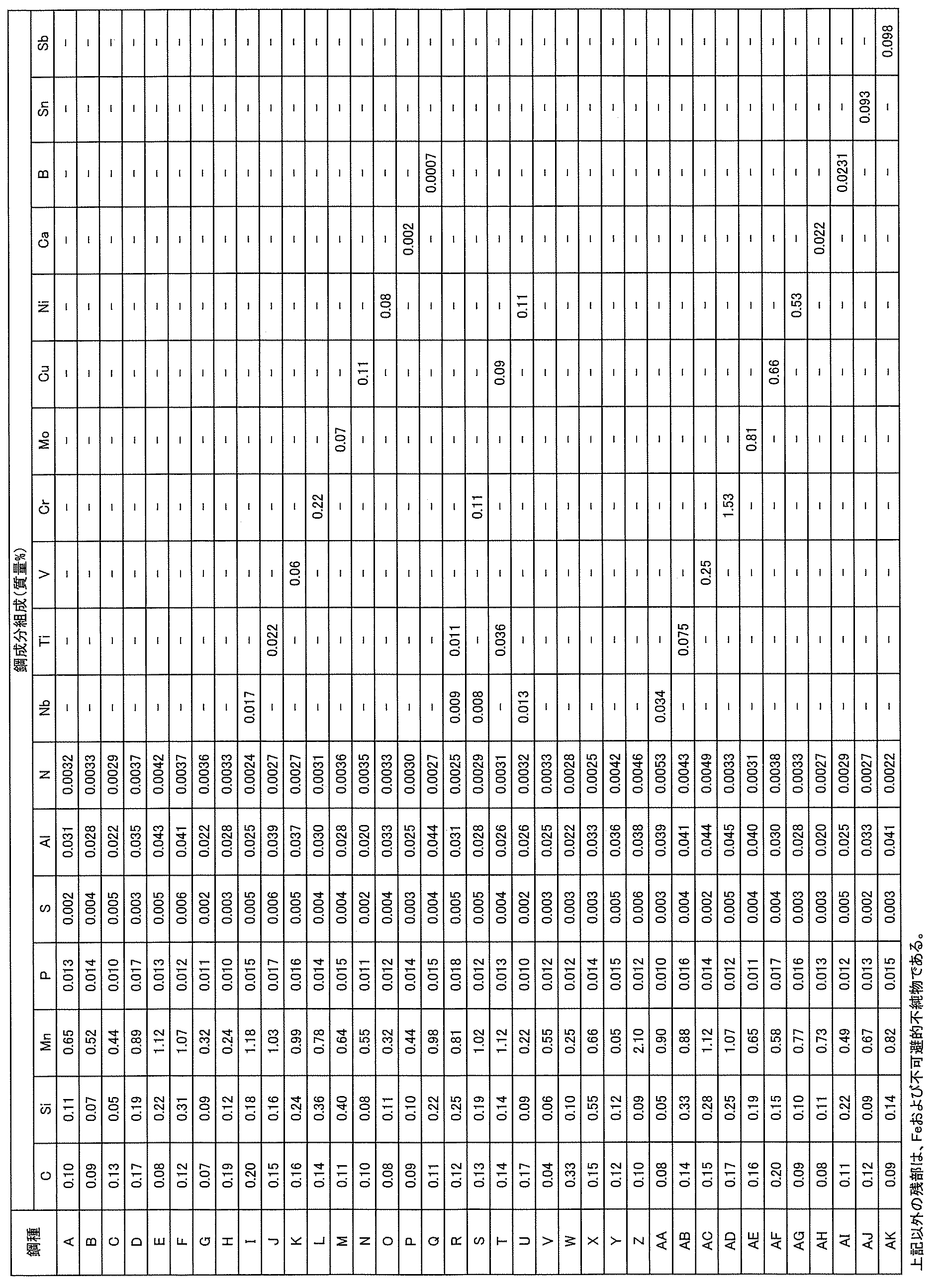
- Molten steel having the steel composition shown in Table 1 was cast to produce steel material (steel slab).
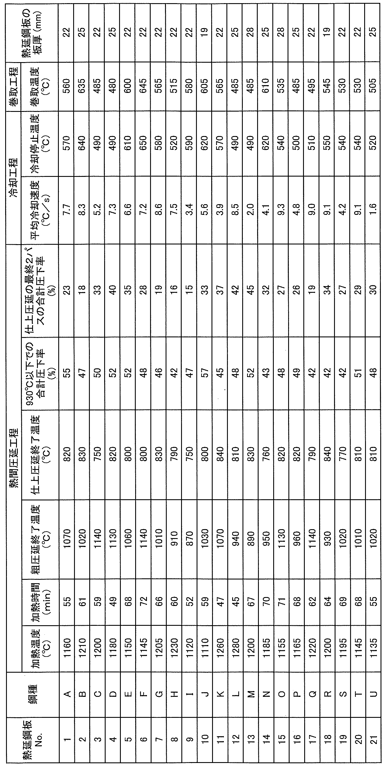
- the resulting steel slab was subjected to the hot rolling process, cooling process, and coiling process under the conditions shown in Tables 2-1 and 2-2 to produce hot-rolled steel sheet.
- the pipe-making process shown below was then carried out.
- the obtained hot-rolled steel sheet was formed into a cylindrical open pipe by roll forming (cold roll forming), and the butt joints were electric resistance welded to form a round steel pipe.
- the round steel pipe was then formed into a square steel pipe (square in cross section perpendicular to the axial direction) by rolls arranged above, below, left and right of the round steel pipe.
- the obtained square steel pipe had corners and flat parts, and had the side length (mm) and wall thickness (mm) shown in Tables 3-1 and 3-2.
- the resulting rectangular steel pipe was cut to a length of 3.0 m and then compressive strain was applied in the length direction (pipe axis direction) to produce a rectangular steel pipe. Note that to prevent buckling of the rectangular steel pipe, the cut surface was ground and parallelized before compressive strain was applied.
- the compressive strain value was evaluated by the value of a strain gauge attached to the center of the width of the flat part on the outer surface of the steel pipe (the 3 o'clock side when the weld is at the 12 o'clock direction) at the center of the length of the rectangular steel pipe (1.5 m from the end).
- Test pieces were taken from the hot-rolled steel plates or square steel pipes manufactured as above, and the following structural observations, tensile tests, and Charpy impact tests were carried out.
- the test pieces for microstructural observation were taken from the center in the width direction and the center in the thickness direction of the hot-rolled steel sheet (at a position of t/2 of the sheet thickness (t: sheet thickness)).
- the observation surface was set to be a cross section in the rolling direction during hot rolling, polished, and then etched with nital to prepare the observation surface.
- the structure was observed using an optical microscope (magnification: 1000x) at the thickness t/2 position (center of thickness) of the hot-rolled steel plate, and optical microscope images were taken. From the optical microscope images obtained, the area ratios of ferrite, pearlite, pseudo-pearlite, and upper bainite were determined.
- ferrite is a product of diffusion transformation, and has a low dislocation density and a nearly restored structure. This includes polygonal ferrite and pseudo-polygonal ferrite.
- Pearlite is a structure in which cementite and ferrite are arranged in layers
- pseudo-pearlite is a structure in which cementite arranged in dot rows in ferrite is confirmed.
- Upper bainite is a complex phase structure of lath-shaped ferrite and cementite with high dislocation density. In addition to the above shapes, ferrite is white, pearlite is black, pseudo-pearlite is black or gray, and upper bainite is white or gray, which are the reasons for the distinction.
- the number density (pieces/ mm2 ) of pearlite and pseudo-pearlite was calculated by observing five visual fields, adding up the number of pearlite and pseudo-pearlite observed in the five visual fields, and dividing the total by the observation area ( mm2 ).
- the number of pearlite and pseudo-pearlite was measured by measuring the total number of pearlite and pseudo-pearlite with a circle equivalent diameter of 2 ⁇ m to 20 ⁇ m and the total number of pearlite and pseudo-pearlite with a circle equivalent diameter of more than 20 ⁇ m.
- the number density of pearlite and pseudo-pearlite with a circle equivalent diameter of 2 ⁇ m to 20 ⁇ m and the number density of pearlite and pseudo-pearlite with a circle equivalent diameter of more than 20 ⁇ m were calculated.
- the average grain size (average circle equivalent diameter) was measured at the sheet thickness t/2 position (sheet thickness center) using the SEM/EBSD method.
- the grain size was measured by obtaining the orientation difference between adjacent grains, and the boundary with an orientation difference of 15° or more was taken as the grain boundary.
- the grain size (circle equivalent diameter) of each grain was calculated from the obtained grain boundary, and the arithmetic average was calculated to be the average grain size (average circle equivalent diameter). In the grain size analysis, grains with a grain size of less than 2.0 ⁇ m were excluded from the analysis as measurement noise.
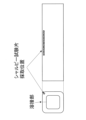
- FIG. 2 is a schematic diagram showing the position where the tensile test specimens of the flat plate portion were taken.
- the tensile test was performed by taking JIS No. 5 tensile test specimens from the flat plate portion of the square steel pipe so that the tensile direction was parallel to the pipe axis direction.
- the taken tensile test specimens were subjected to a tensile test in accordance with the provisions of JIS Z 2241 (2011), and the yield strength (YS), tensile strength (TS), uniform elongation (Eu), and fracture elongation (Et) were measured, and the yield ratio defined as (yield strength)/(tensile strength) was calculated.
- the uniform elongation was taken as the total elongation value at the maximum load.
- the tensile test specimens of the flat plate portion were taken from the position of the width center of the flat plate portion and the length center of the square steel pipe at the 3 o'clock side when the welded portion of the square steel pipe is in the 12 o'clock direction (see FIG. 2).
- the number of test specimens was two, and the average values of these were calculated to obtain YS, TS, yield ratio, uniform elongation, and fracture elongation.
- a plate portion with a yield strength of 295 MPa or more and a tensile strength of 400 MPa or more was deemed to have passed the test.
- a plate portion with a yield ratio of 0.85 or less was deemed to have passed the test as having a low yield ratio.
- a plate portion with a uniform elongation of 8.0% or more and a fracture elongation of 27.0% or more was deemed to have passed the test as having high ductility.
- FIG. 3 is a schematic diagram showing the sampling position of the Charpy test piece used in the Charpy impact test.
- the Charpy test piece was sampled from the corner of the square steel pipe at a t/4 position of the wall thickness t from the outer surface of the square steel pipe so that the longitudinal direction of the test piece was parallel to the pipe axis direction.
- the V-notch standard test piece was sampled from the t/2 position of the wall thickness t from the outer surface of the square steel pipe.
- the Charpy impact test was performed at test temperatures: -70 ° C, -50 ° C, -30 ° C, -10 ° C, and 10 ° C.
- the number of test pieces was three at each test temperature, and the ductile-brittle transition temperature and the average value (J) of absorbed energy were obtained.
- a test temperature of -10°C and an absorbed energy of 80 J or more in a Charpy impact test and a ductile-brittle transition temperature of -10°C or less were deemed to pass the test as being excellent in low-temperature toughness.
- the rectangular steel pipes of the present invention all had a yield strength of 295 MPa or more in the flat portion and a tensile strength of 400 MPa or more in the flat portion. They also had a low yield ratio of 0.85 or less in the flat portion. They also had high ductility with a uniform elongation of 8.0% or more in the flat portion and a fracture elongation of 27.0% or more in the flat portion. They also had excellent low-temperature toughness with a Charpy absorbed energy of 80 J or more at the corners at -10°C and a ductile-brittle transition temperature of -10°C or less at the corners.
- the C content was below the range of the present invention, so the area ratio of the second phase was outside the range of the present invention, and the yield strength, tensile strength, and yield ratio did not reach the desired values.
- the C content was higher than the range of the present invention, so the area ratio of the second phase was outside the range of the present invention, and the Charpy absorbed energy at the corner at -10°C, the ductile-brittle transition temperature, the uniform elongation and the fracture elongation did not reach the desired values.
- Step X the Si content exceeded the range of the present invention, so that the toughness was reduced, and the Charpy absorbed energy at the corner at -10°C, the ductile-brittle transition temperature, the uniform elongation and the fracture elongation did not reach the desired values.
- No. 25 the Mn content was below the range of the present invention, so the area ratio of the second phase was outside the range of the present invention, and the tensile strength and yield ratio did not reach the desired values.
- No. 26 the Mn content exceeded the range of the present invention, so that the amount of upper bainite formed was large, and the yield ratio did not reach the desired value.
- Step U the compressive strain was below the range of the present invention, and therefore the yield ratio, uniform elongation and fracture elongation did not reach the desired values.
- No. 47 the compressive strain exceeded the range of the present invention, and therefore buckling occurred in the square steel pipe. Therefore, the tensile test and the Charpy test were not performed.
- the heating time of the steel material was below the range of the present invention, so that ferrite was generated excessively and the area ratio of the second phase was outside the range of the present invention. Therefore, the yield strength, tensile strength and yield ratio did not reach the desired values.
- the heating time of the steel material exceeded the range of the present invention, so that the average grain size and the number density of pearlite and pseudo-pearlite having a circle equivalent diameter of 2 ⁇ m to 20 ⁇ m were outside the range of the present invention.
- the uniform elongation, the fracture elongation, the Charpy absorbed energy at the corner at -10°C, and the ductile-brittle transition temperature did not reach the desired values.
- the total reduction rate of the final two passes of finish rolling was below the range of the present invention, so the number density of pearlite and pseudo-pearlite with a circle equivalent diameter of 2 ⁇ m to 20 ⁇ m was outside the range of the present invention. Therefore, the uniform elongation, fracture elongation, Charpy absorbed energy at the corner at -10 ° C, and ductile-brittle transition temperature did not reach the desired values.
Landscapes
- Chemical & Material Sciences (AREA)
- Engineering & Computer Science (AREA)
- Mechanical Engineering (AREA)
- Materials Engineering (AREA)
- Metallurgy (AREA)
- Organic Chemistry (AREA)
- Physics & Mathematics (AREA)
- Thermal Sciences (AREA)
- Crystallography & Structural Chemistry (AREA)
- Manufacturing & Machinery (AREA)
- Heat Treatment Of Steel (AREA)
Abstract
Description
(2)角形鋼管の板厚中心部の鋼組織において、パーライト、擬似パーライトおよび上部ベイナイトから選択される1種または2種以上からなる第2相を有し、第2相の面積率を5~30%とする必要がある。さらに、前記鋼組織において、平均結晶粒径を10.0~30.0μmとし、かつ円相当径が2μm以上20μm以下のパーライトおよび擬似パーライトが合計で500個/mm2以上存在することが必要である。
(3)上記鋼組織を得るためには、角形鋼管の素材となる熱延鋼板を製造する際の熱間圧延における圧下率を適切な範囲にすることが極めて重要である。具体的には、930℃以下での合計圧下率:40%以上、かつ仕上圧延の最終2パスの合計圧下率が15%以上であることが必要である。
(4)さらに、角形鋼管を製造する際に、熱延鋼板を丸形状の鋼管に成形した後、および/または角形状の鋼管に成形した後、管軸方向に0.20~3.00%の圧縮ひずみを付与することが必要である。
[1]平板部と角部を有する角形鋼管であって、
鋼成分組成は、質量%で、
C:0.07%以上0.20%以下、
Si:0.01%以上0.40%以下、
Mn:0.20%以上1.20%以下、
P:0.10%以下、
S:0.050%以下、
Al:0.005%以上0.100%以下、および
N:0.010%以下
を含み、残部がFeおよび不可避的不純物からなり、
前記平板部の板厚中心部の鋼組織は、フェライトを主相とし、パーライト、擬似パーライトおよび上部ベイナイトから選択される1種または2種以上からなる第2相の面積率が5~30%であり、平均結晶粒径が10.0~30.0μmであり、かつ前記鋼組織には、円相当径が2μm以上20μm以下のパーライトおよび擬似パーライトが合計で500個/mm2以上存在し、
前記平板部の降伏強度が295MPa以上、前記平板部の引張強度が400MPa以上、前記平板部の降伏比が0.85以下、前記平板部の均一伸びが8.0%以上、前記平板部の破断伸びが27.0%以上であり、
前記角部の-10℃におけるシャルピー吸収エネルギーが80J以上、前記角部の延性-脆性遷移温度が-10℃以下である、角形鋼管。
[2]前記鋼成分組成は、さらに、質量%で、
Nb:0.020%以下、
Ti:0.045%以下、
V:0.10%以下、
Cr:0.50%以下、
Mo:0.50%以下、
Cu:0.30%以下、
Ni:0.30%以下、
Ca:0.0100%以下、
B:0.0100%以下、
Sn:0.100%以下、および
Sb:0.100%以下
のうちから選ばれた1種または2種以上を含有する、[1]に記載の角形鋼管。
[3]前記[1]または[2]に記載の角形鋼管の製造方法であって、
前記鋼成分組成を有する鋼素材を加熱温度:1100℃以上1300℃以下、加熱時間:40min以上200min以下で加熱した後、粗圧延終了温度:850℃以上1150℃以下、仕上圧延終了温度:750℃以上850℃以下、930℃以下での合計圧下率:40%以上、かつ仕上圧延の最終2パスの合計圧下率:15%以上である熱間圧延を施し、次いで、
板厚中心部の平均冷却速度:10.0℃/s以下、板厚中心部の冷却停止温度:480℃以上650℃以下で冷却を施し、次いで、
板厚中心部の温度:480℃以上650℃以下で巻取り熱延鋼板とし、次いで、
ロール成形により、前記熱延鋼板を円筒状に成形した後、前記熱延鋼板の端部を溶接して丸形状の鋼管に成形し、その後、角形状の鋼管に成形して角形鋼管とする際に、前記丸形状の鋼管に成形した後、および/または前記角形状の鋼管に成形した後、管軸方向に0.20~3.00%の圧縮ひずみを付与する、角形鋼管の製造方法。
[4]前記[1]または[2]に記載の角形鋼管が柱材として用いられた、建築構造物。
Cは、固溶強化により鋼の強度を上昇させる元素である。また、Cは、第2相の一つであるパーライトおよび擬似パーライトの形成に寄与する元素である。本発明で目的とする強度および降伏比を確保するためには、0.07%以上のCを含有することが必要である。しかしながら、C含有量が0.20%を超えると、硬質相の割合が高くなり低温靱性が低下し、また降伏比が0.85を超え所望の降伏比が得られなくなる。さらには、延性が低下し、所望の均一伸びおよび破断伸びが得られなくなる。また、溶接性も悪化する。このため、C含有量は0.07%以上0.20%以下とする。C含有量は、好ましくは0.08%以上である。また、C含有量は、好ましくは0.19%以下であり、より好ましくは0.18%以下である。
Siは、固溶強化により鋼の強度を上昇させる元素である。このような効果を得るためには、0.01%以上のSiを含有することが必要である。しかし、Si含有量が0.40%を超えると、電縫溶接部に酸化物が生成しやすくなり溶接部特性が低下し、また延性が低下して所望の均一伸びおよび破断伸びが得られなくなる。さらに、電縫溶接部以外の母材部の靱性も低下する。このため、Si含有量は0.40%以下とする。Si含有量は、好ましくは0.02%以上であり、より好ましくは0.05%以上である。また、Si含有量は、好ましくは0.37%以下であり、より好ましくは0.35%以下である。
Mnは、固溶強化および/またはベイナイトの生成量を増加させることにより鋼の強度を上昇させる元素である。また、Mnはフェライト変態開始温度を低下させることで組織の微細化に寄与する元素である。本発明で目的とする強度および組織を確保するためには、0.20%以上のMnを含有することが必要である。しかしながら、Mn含有量が1.20%を超えると、ベイナイトの生成量が多くなり降伏比が0.85を超え、所望の降伏比が得られなくなる。また、Mn含有量が1.20%を超えると、中心偏析部の硬度が上昇し、溶接時に割れの原因となる可能性が有る。このため、Mn含有量は0.20%以上1.20%以下とする。Mn含有量は、好ましくは0.25%以上であり、より好ましくは0.30%以上である。また、Mn含有量は、好ましくは1.10%以下であり、より好ましくは1.05%以下である。
Pは、粒界に偏析し材料の不均質を招くため、不可避的不純物としてできるだけ低減することが好ましいが、0.10%の含有量までは許容できる。このため、P含有量は0.10%以下の範囲内とする。P含有量は、好ましくは0.030%以下であり、より好ましくは0.020%以下である。なお、特にP含有量の下限は規定しないが、過度の低減は製錬コストの高騰を招くため、P含有量は0.002%以上とすることが好ましい。
Sは、鋼中では通常、MnSとして存在するが、MnSは熱間圧延工程で薄く延伸され、延性に悪影響を及ぼす。このため、本発明ではSをできるだけ低減することが好ましいが、0.050%以下の含有量までは許容できる。このため、S含有量は0.050%以下とする。S含有量は、好ましくは0.015%以下であり、より好ましくは0.010%以下であり、より一層好ましくは0.008%以下である。なお、特にS含有量の下限は規定しないが、過度の低減は製錬コストの高騰を招くため、S含有量は0.0002%以上とすることが好ましい。
Alは、強力な脱酸剤として作用する元素である。このような効果を得るためには、0.005%以上のAlを含有することが必要である。しかし、Al含有量が0.100%を超えると溶接性が悪化するとともに、アルミナ系介在物が多くなり、表面性状が悪化する。また溶接部の靱性も低下する。このため、Al含有量は0.005%以上0.100%以下とする。Al含有量は、好ましくは0.010%以上であり、より好ましくは0.015%以上である。また、Al含有量は、好ましくは0.070%以下であり、より好ましくは0.050%以下である。
Nは、不可避的不純物であり、転位の運動を強固に固着することで靱性を低下させる作用を有する元素である。本発明では、Nは不純物としてできるだけ低減することが望ましいが、Nの含有量は0.010%までは許容できる。このため、N含有量は0.010%以下とする。N含有量は、好ましくは0.0080%以下であり、より好ましくは0.0040%以下であり、より一層好ましくは0.0035%以下である。なお、過度の低減は製錬コストの高騰を招くため、N含有量は0.0010%以上とすることが好ましく、0.0015%以上とすることがより好ましい。
上記鋼成分組成を有することで、本発明で目的とする特性が得られる。
NbおよびTiはそれぞれ、鋼中で微細な炭化物、窒化物を形成し、析出強化を通じて鋼の強度向上に寄与する元素である。このような効果を得るため、Nb、Tiのそれぞれについて、0.005%以上含有することが好ましく、0.007%以上含有することがより好ましい。しかし、Nbの含有量が0.020%を超えると、降伏比が0.85を超え所望の降伏比が得られなくなる。また、Tiの含有量が0.045%を超えると、粗大な炭化物、窒化物が形成され、低温靱性および延性の低下を招く恐れがある。そのため、Nb、Tiを含有する場合には、Nb、Tiの含有量をそれぞれNb:0.020%以下、Ti:0.045%以下とする。Nb含有量は、好ましくはNb:0.018%以下であり、より好ましくは0.016%以下である。また、Ti含有量は、好ましくはTi:0.040%以下であり、より好ましくはTi:0.035%以下である。
V、Cr、Moはそれぞれ、鋼の焼入れ性を高め、鋼の強度を上昇させる元素であり、必要に応じて含有することができる。このような効果を得るため、V、Cr、Moを含有する場合には、それぞれV:0.01%以上、Cr:0.01%以上、Mo:0.01%以上含有することが好ましく、V:0.02%以上、Cr:0.10%以上、Mo:0.10%以上含有することがより好ましい。しかし、V、Cr、Moの含有量がそれぞれ、V:0.10%超、Cr:0.50%超、Mo:0.50%超となると、延性が低下し所望の均一伸びおよび破断伸びが得られなくなり、また、低温靱性の低下を招く恐れがある。そのため、V、Cr、Moを含有する場合には、それぞれV:0.10%以下、Cr:0.50%以下、Mo:0.50%以下とする。V、Cr、Moの含有量はそれぞれ、好ましくは、V:0.08%以下、Cr:0.40%以下、Mo:0.40%以下である。
Cu、Niはそれぞれ、固溶強化により鋼の強度を上昇させる元素であり、必要に応じて含有することができる。このような効果を得るため、Cu、Niを含有する場合には、Cu、Ni含有量はそれぞれ、Cu:0.01%以上、Ni:0.01%以上とすることが好ましく、Cu:0.10%以上、Ni:0.10%以上とすることがより好ましい。しかし、Cu含有量が0.30%超になると低温靱性の低下を招き所望の低温靱性が得られなくなり、またNi含有量が0.30%超になると降伏比が0.85を超え所望の降伏比が得られなくなる。そのため、Cu、Niを含有する場合には、Cu、Ni含有量をそれぞれ、Cu:0.30%以下、Ni:0.30%以下とする。Cu、Ni含有量はそれぞれ、好ましくは、Cu:0.20%以下、Ni:0.20%以下である。
Caは、熱間圧延工程で薄く延伸されるMnS等の硫化物を球状化することで鋼の靱性向上に寄与する元素であり、必要に応じて含有できる。このような効果を得るため、Caを含有する場合には、Ca含有量は0.0005%以上とすることが好ましく、0.0010%以上とすることがより好ましい。しかし、Ca含有量が0.0100%を超えると、延性が低下し所望の均一伸びおよび破断伸びが得られなくなり、また低温靱性が低下して所望の低温靱性が得られなくなる。そのため、Caを含有する場合には、Ca含有量は0.0100%以下とする。Ca含有量は、好ましくは0.0050%以下である。
Bは、フェライト変態開始温度を低下させることで組織の微細化に寄与する元素である。このような効果を得るため、Bを含有する場合には、B含有量は、0.0003%以上が好ましく、0.0005%以上がより好ましい。しかし、B含有量が0.0100%を超えると、上部ベイナイトの生成量が多くなり、降伏比が0.85を超え所望の降伏比が得られない。そのため、Bを含有する場合には、B含有量は0.0100%以下とする。B含有量は、好ましくは0.0050%以下である。
Snは、固溶強化により鋼の強度を上昇させる元素であり、必要に応じて含有することができる。上記した効果を得るため、Snを含有する場合には、Sn含有量は、0.001%以上が好ましく、0.002%以上がより好ましく、0.005%以上がさらに好ましい。しかし、Sn含有量が0.100%を超えると、熱間加工性が低下して熱間圧延時に割れが発生する可能性がある。このため、Snを含有する場合には、Sn含有量は0.100%以下とする。Sn含有量は、好ましくは0.070%以下であり、より好ましくは0.050%以下である。
Sbは、固溶強化により鋼の強度を上昇させる元素であり、必要に応じて含有することができる。上記した効果を得るため、Sbを含有する場合には、Sb含有量は、0.001%以上が好ましく、0.002%以上がより好ましく、0.005%以上がさらに好ましい。しかし、Sb含有量が0.100%を超えると、熱間加工性が低下して熱間圧延時に割れが発生する可能性がある。このため、Sbを含有する場合には、Sb含有量は0.100%以下とする。Sb含有量は、好ましくは0.070%以下であり、より好ましくは0.050%以下である。
フェライトは軟質な組織であり、所望の降伏強度および低降伏比を得るため、本発明において主相とする。本発明において、主相とは、面積率で70%以上を占める相を意味する。フェライトの面積率が70%未満であると、降伏応力が過度に大きくなり、また所望の降伏比が得られない場合がある。そのため、フェライトは面積率で70%以上であり、好ましくは72%以上である。一方、フェライトの面積率が95%を超えると強度が低下し、所望の降伏強度および引張強度が得られない場合がある。そのため、好ましくは、フェライトは面積率で95%以下であり、より好ましくは、フェライトは面積率で93%以下である。
パーライト、擬似パーライトおよび上部ベイナイトは、フェライトに比べて硬質な組織であり、鋼の強度を上昇させ、また低降伏比を得るために重要な鋼組織である。本発明で目的とする降伏強度、引張強度、降伏比を得るためには、パーライト、擬似パーライトおよび上部ベイナイトから選択される1種または2種以上からなる第2相の面積率が5%以上であることが必要である。前記面積率は、好ましくは6%以上であり、より好ましくは8%以上である。一方、パーライト、擬似パーライトおよび上部ベイナイトから選択される1種または2種以上からなる第2相の面積率が30%を超えると低温靱性が悪化し、降伏比が上昇する場合がある。そのため、パーライト、擬似パーライトおよび上部ベイナイトから選択される1種または2種以上からなる第2相の面積率は30%以下であることが必要である。前記面積率は、好ましくは28%以下であり、より好ましくは26%以下である。
上述のとおり、本発明の鋼組織は、本発明で目的とする低降伏比、降伏強度、および引張強度を得るために、軟質組織と硬質組織を混合させた鋼(以下、「複合組織鋼」と称する)とする。しかし、複合組織鋼は、単一組織鋼と比較して靱性が劣る。そこで、本発明では、上記の機械特性と優れた靱性を両立するため、隣り合う結晶の方位差(結晶方位差)が15°以上の境界によって囲まれた領域を結晶粒としたとき、平板部の板厚中心部の鋼組織の平均結晶粒径を規定する。平板部の板厚中心部の鋼組織の平均結晶粒径(円相当径)が10.0μm未満であると、降伏比が増加して本発明で目的とする降伏比が得られない。一方、前記鋼組織の平均結晶粒径が30.0μmを超えると、低温靱性が悪化する。そのため、平板部の板厚中心部の鋼組織の平均結晶粒径は10.0~30.0μmであることが必要である。前記平均結晶粒径は、好ましくは11.0μm以上であり、より好ましくは11.5μm以上である。また、前記平均結晶粒径は28.0μm以下が好ましく、より好ましくは26.0μm以下である。
鋼素材の加熱温度が1100℃未満である場合、被圧延材である鋼素材の変形抵抗が大きくなり圧延が困難となる。一方、鋼素材の加熱温度が1300℃を超えると、オーステナイト粒が粗大化し、後の圧延(粗圧延、仕上圧延)において微細なオーステナイト粒が得られない。その結果、本発明で目的とする熱延鋼板の板厚中心部の鋼組織(以下、板厚中心部の鋼組織を、単に、鋼組織ともいう)の平均結晶粒径を確保することが困難となる。このため、熱間圧延工程における鋼素材の加熱温度は、1100℃以上1300℃以下とする。前記加熱温度は、好ましくは1120℃以上である。また、前記加熱温度は、好ましくは1280℃以下である。なお、本発明では、鋼素材(鋼スラブ)を製造した後、一旦室温まで冷却し、その後再度加熱する従来法に加え、室温まで冷却しないで、温片のままで加熱炉に装入する、直送圧延の省エネルギープロセスも問題なく適用できる。
所望の鋼組織(平均結晶粒径、円相当径が2μm以上20μm以下のパーライトおよび擬似パーライトの数密度)を得るため、本発明では鋼素材の加熱温度に加え、加熱時間を厳密に規定する。鋼素材の加熱時間が40min未満である場合、オーステナイト粒が微細になりすぎて、冷却工程においてフェライトが過剰に生成し、降伏強度および引張強度が低下する。一方、鋼素材の加熱時間が200minを超えると、オーステナイトが粗大になり、平均結晶粒径が10.0~30.0μmである鋼組織を得ることが困難となる。また、円相当径が2μm以上20μm以下のパーライトおよび擬似パーライトが500個/mm2以上である鋼組織を得ることが困難となる。このため、鋼素材の加熱時間は40min以上200min以下とする。前記加熱時間は、好ましくは45min以上であり、より好ましくは50min以上である。また、前記加熱時間は、好ましくは190min以下であり、より好ましくは185min以下である。なお、前記加熱時間は、鋼素材を加熱炉に装入してから取り出すまでの時間である。
粗圧延終了温度が850℃未満である場合、後の仕上圧延中に鋼板表面温度がフェライト変態開始温度以下になり、多量のフェライトが生成し、降伏強度および引張強度が低下する。一方、粗圧延終了温度が1150℃を超えると、オーステナイト未再結晶温度域での圧下量が不足し、微細なオーステナイト粒が得られない。その結果、平均結晶粒径が10.0~30.0μmである鋼組織を得ることが困難となる。このため、粗圧延終了温度は、850℃以上1150℃以下とする。粗圧延終了温度は、好ましくは860℃以上であり、より好ましくは870℃以上である。また、粗圧延終了温度は、好ましくは1100℃以下であり、より好ましくは1050℃以下である。
仕上圧延終了温度が750℃未満である場合、仕上圧延中に鋼板表面温度がフェライト変態開始温度以下になり、圧延方向に伸長したフェライトが形成され、加工性が低下する可能性が有る。一方、仕上圧延終了温度が850℃を超えると、オーステナイト未再結晶温度域での圧下量が不足し、微細なオーステナイト粒が得られない。その結果、結晶粒が粗大になり、本発明で目的とする強度(降伏強度、引張強度)の確保が困難となる。このため、仕上圧延終了温度は、750℃以上850℃以下とする。仕上圧延終了温度は、好ましくは770℃以上であり、より好ましくは780℃以上である。また、仕上圧延終了温度は、好ましくは830℃以下であり、より好ましくは820℃以下である。
本発明では、熱間圧延工程においてオーステナイト中のサブグレインを微細化することで、続く冷却工程、巻取工程で生成するフェライト、ベイナイトを微細化し、本発明で目的とする強度および低温靱性を有する熱延鋼板の鋼組織を得られる。熱間圧延工程においてオーステナイト中のサブグレインを微細化するためには、オーステナイト未再結晶温度域での圧下率を高くし、十分な加工ひずみを導入する必要がある。930℃以下での合計圧下率が40%未満となると、フェライトやベイナイトの結晶粒径が大きくなり、低温靱性の低下を招く。そのため、930℃以下での合計圧下率は40%以上とした。前記合計圧下率は、好ましくは42%以上であり、より好ましくは45%以上である。なお、前記合計圧下率が大きすぎると熱間圧延工程の製造設備に過大な負荷がかかり製造が困難となるため、前記合計圧下率は60%以下が好ましい。
所望の鋼組織、特に所望の円相当径が2μm以上20μm以下のパーライトおよび擬似パーライトの数密度を得るため、本発明では仕上圧延の最終2パスの合計圧下率を規定する。仕上圧延の最終2パスの合計圧下率が15%未満であると、粗大なパーライトが生成するため、円相当径が2μm以上20μm以下のパーライトおよび擬似パーライトが500個/mm2以上である鋼組織を得ることが困難となる。そのため、仕上圧延の最終2パスの合計圧下率を15%以上とする。好ましくは17%以上であり、より好ましくは19%以上である。仕上圧延の最終2パスの合計圧下率の上限は特に設けないが、前記合計圧下率が50%超になると、圧延設備にかかる負荷が増大するため、仕上圧延の最終2パスの合計圧下率は50%以下であることが好ましく、より好ましくは48%以下である。
熱延板の板厚中心部の温度で、冷却開始から後述する冷却停止までの温度域における平均冷却速度が10.0℃/sを超えると、上部ベイナイトの生成量が多くなり、また所望の平均結晶粒径が得られなくなり、本発明で目的とする降伏比が得られない。よって、前記平均冷却速度は10.0℃/s以下とする。前記平均冷却速度は、好ましくは9.5℃/s以下であり、より好ましくは9.0℃/s以下である。なお、前記平均冷却速度の下限は、特に限定されないが、前記平均冷却速度が1.0℃/s未満では、後述する冷却停止温度を得にくくなる。よって、前記平均冷却速度は、好ましくは1.0℃/s以上であり、より好ましくは1.5℃/s以上であり、さらに好ましくは2.0℃/s以上である。なお、本発明では、結晶粒径が粗大になることを抑制する観点から、仕上圧延終了後直ちに冷却を開始することが好ましい。
熱延板の板厚中心部の温度で、冷却停止温度が480℃未満では、上部ベイナイトの生成量が多くなり、降伏比が0.85を超え所望の降伏比が得られない場合がある。また、冷却中に熱延板の長さ方向および/または幅方向で温度ムラが生じやすく、機械特性にバラつきが生じる可能性が有る。一方で、熱延板の板厚中心部の温度で、冷却停止温度が650℃を超えると、フェライト粒が粗大化し、所望の結晶粒径が得られない。よって、熱延板の板厚中心部の温度で、冷却停止温度は480℃以上650℃以下とする。前記冷却停止温度は、好ましくは490℃以上であり、より好ましくは495℃以上である。前記冷却停止温度は、好ましくは640℃以下であり、より好ましくは635℃以下である。
鋼管の管軸方向に圧縮ひずみを付与すると、管軸方向の降伏比が低下し、延性が増加(均一伸びおよび破断伸びが上昇)する。そのため、本発明で所望とする低降伏比、高延性(高い均一伸びおよび高い破断伸び)を得るために、圧縮ひずみを付与する工程は最も重要である。圧縮ひずみが0.20%未満では、降伏比を低下、延性を高める(均一伸びおよび破断伸びを上昇させる)効果が得られない。一方、圧縮ひずみが3.00%を超えると鋼管が座屈する可能性がある。そのため、管軸方向の圧縮ひずみは0.20~3.00%とする。圧縮ひずみは、好ましくは0.25%以上であり、より好ましくは0.30%以上である。圧縮ひずみは、好ましくは2.80%以下であり、より好ましくは2.60%以下である。座屈が生じなければ、圧縮ひずみを付与する方法は問わない。また、圧縮ひずみは、成形した丸形状の鋼管または角形状の鋼管のいずれかに付与するか、丸形状の鋼管と角形状の鋼管の両方に付与してもよい。丸形状の鋼管と角形状の鋼管の両方に付与する場合は、丸形状の鋼管と角形状の鋼管のそれぞれに付与した圧縮ひずみの合計が上記した範囲になるようにする。
図1は、本発明の建築構造物の一例を示す模式図である。

組織観察用の試験片は、熱延鋼板の幅方向中央部かつ板厚中心部(板厚t/2の位置(t:板厚))から採取した。観察面が熱間圧延時の圧延方向断面となるようにし、研磨した後、ナイタール腐食して観察面を作製した。
図2は、平板部の引張試験片の採取位置を示す概略図である。図2に示すように、引張試験は、引張方向が管軸方向と平行になるように、角形鋼管の平板部からJIS 5号引張試験片を採取して行った。採取した引張試験片について、JIS Z 2241(2011)の規定に準拠して引張試験を実施し、降伏強度(YS)、引張強度(TS)、均一伸び(Eu)、破断伸び(Et)を測定し、(降伏強度)/(引張強度)で定義される降伏比を算出した。均一伸びは最大荷重時の全伸びの値とした。なお、平板部の引張試験片は、角形鋼管の溶接部を12時方向としたときの3時の辺部における、平板部の幅中央部の位置且つ角形鋼管の長さ方向中央部から採取した(図2を参照)。試験片本数は2本とし、それらの平均値を算出してYS、TS、降伏比、均一伸び、破断伸びを求めた。強度については、平板部の降伏強度:295MPa以上、かつ引張強度:400MPa以上を合格とした。降伏比については、降伏比:0.85以下を、低降伏比を有するとして合格とした。延性については、均一伸び:8.0%以上、かつ破断伸び:27.0%以上を、高延性を有するとして合格とした。
シャルピー衝撃試験は、JIS Z 2242(2018)の規定に準拠したVノッチ標準試験片を用いて行った。図3は、シャルピー衝撃試験に用いたシャルピー試験片の採取位置を示す概略図である。図3に示すように、シャルピー試験片は、角形鋼管の管外面から肉厚tのt/4位置において、試験片長手方向が管軸方向と平行となるように、角形鋼管の角部から採取した。ただし、肉厚19mm以下の角形鋼管については、角形鋼管の管外面から肉厚tのt/2位置からVノッチ標準試験片を採取した。JIS Z 2242(2018)の規定に準拠して、試験温度:-70℃、-50℃、-30℃、-10℃、10℃でシャルピー衝撃試験を実施した。試験片本数は各試験温度で3本とし、延性-脆性遷移温度および吸収エネルギーの平均値(J)を求めた。試験温度:-10℃でのシャルピー衝撃試験の吸収エネルギー:80J以上、かつ延性-脆性遷移温度:-10℃以下を、低温靱性に優れるとして合格とした。


比較例のNo.23(鋼W)は、Cの含有量が本発明の範囲を上回っていたため、第2相の面積率が本発明の範囲外となり、-10℃における角部のシャルピー吸収エネルギー、延性-脆性遷移温度、均一伸びおよび破断伸びが所望の値に達しなかった。
比較例のNo.24(鋼X)は、Siの含有量が本発明の範囲を上回ったため、靱性が低下し、-10℃における角部のシャルピー吸収エネルギー、延性-脆性遷移温度、均一伸びおよび破断伸びが所望の値に達しなかった。
比較例のNo.25(鋼Y)は、Mnの含有量が本発明の範囲を下回ったため、第2相の面積率が本発明の範囲外となり、引張強度および降伏比が所望の値に達しなかった。
比較例のNo.26(鋼Z)は、Mnの含有量が本発明の範囲を上回ったため、上部ベイナイトの生成量が多くなり、降伏比が所望の値に達しなかった。
比較例のNo.28(鋼AB)は、Tiの含有量が本発明の範囲を上回ったため、粗大な炭化物や窒化物の形成が生じたと考えられる。その結果、-10℃における角部のシャルピー吸収エネルギー、延性-脆性遷移温度および均一伸びが所望の値に達しなかった。
比較例のNo.29(鋼AC)は、Vの含有量が本発明の範囲を上回ったため、靱性および延性が低下した。その結果、-10℃における角部のシャルピー吸収エネルギー、延性-脆性遷移温度、均一伸び、および破断伸びが所望の値に達しなかった。
比較例のNo.30(鋼AD)は、Crの含有量が本発明の範囲を上回ったため、靱性がおよび延性が低下した。その結果、-10℃における角部のシャルピー吸収エネルギー、延性-脆性遷移温度、および均一伸び、および破断伸びが所望の値に達しなかった。
比較例のNo.31(鋼AE)は、Moの含有量が本発明の範囲を上回ったため、靱性および延性が低下した。その結果、-10℃における角部のシャルピー吸収エネルギー、延性-脆性遷移温度および、均一伸びおよび破断伸びが所望の値に達しなかった。
比較例のNo.33(鋼AG)は、Niの含有量が本発明の範囲を上回ったため、上部ベイナイトの生成量が多くなり、降伏比が所望の値に達しなかった。
比較例のNo.34(鋼AH)は、Caの含有量が本発明の範囲を上回ったため、Ca酸化物クラスターが形成されたと考えられる。その結果、-10℃における角部のシャルピー吸収エネルギー、延性-脆性遷移温度および、均一伸びおよび破断伸びが所望の値に達しなかった。
比較例のNo.35(鋼AI)は、Bの含有量が本発明の範囲を上回ったため、平板部の降伏比が本発明の範囲外となった。
比較例のNo.38(鋼U)は、鋼素材(鋼スラブ)加熱温度が本発明の範囲を上回っており、結晶粒が粗大化し、平均結晶粒径が、本発明の範囲外となった。その結果、降伏強度、引張強度、-10℃における角部のシャルピー吸収エネルギーおよび延性-脆性遷移温度が所望の値に達しなかった。
比較例のNo.40(鋼U)は、仕上圧延終了温度が本発明の範囲を上回ったため、オーステナイトが粗大化し、平均結晶粒径が本発明の範囲外となった。その結果、降伏強度、引張強度、-10℃における角部のシャルピー吸収エネルギーおよび延性-脆性遷移温度が所望の値に達しなかった。
比較例のNo.41(鋼U)は、930℃以下での合計圧下率が本発明の範囲を下回っており、オーステナイトが粗大となり、平均結晶粒径が本発明の範囲外となった。その結果、-10℃における角部のシャルピー吸収エネルギーおよび延性-脆性遷移温度が所望の値に達しなかった。
比較例のNo.42(鋼U)は、板厚中心の平均冷却速度が本発明の範囲を上回ったため、上部ベイナイトの生成量が多くなり、また平均結晶粒径が本発明の範囲外となった。その結果、降伏比が所望の値に達しなかった。
比較例のNo.43(鋼U)は、冷却停止温度および巻取温度が本発明の範囲を下回ったため、上部ベイナイトの生成量が多くなり、降伏比が所望の値に達しなかった。
比較例のNo.45(鋼U)は、巻取温度が本発明の範囲を下回ったため、上部ベイナイトの生成量が多くなり、降伏比が所望の値に達しなかった。
比較例のNo.46(鋼U)は、圧縮ひずみが本発明の範囲を下回ったため、降伏比、均一伸びおよび破断伸びが所望の値に達しなかった。
比較例のNo.47(鋼U)は、圧縮ひずみが本発明の範囲を上回ったため、角形鋼管に座屈が生じた。そのため、引張試験およびシャルピー試験を実施しなかった。
比較例のNo.49(鋼U)は、鋼素材の加熱時間が本発明の範囲を上回ったため、平均結晶粒径および円相当径が2μm以上20μm以下のパーライトおよび擬似パーライトの数密度が本発明の範囲外となった。そのため、均一伸び、破断伸び、-10℃における角部のシャルピー吸収エネルギーおよび延性-脆性遷移温度が所望の値に達しなかった。
比較例のNo.50(鋼U)は、仕上圧延の最終2パスの合計圧下率が本発明の範囲を下回ったため、円相当径が2μm以上20μm以下のパーライトおよび擬似パーライトの数密度が本発明の範囲外となった。そのため、均一伸び、破断伸び、-10℃における角部のシャルピー吸収エネルギーおよび延性-脆性遷移温度が所望の値に達しなかった。
4 大梁
5 小梁
6 ダイアフラム
7 間柱
Claims (4)
- 平板部と角部を有する角形鋼管であって、
鋼成分組成は、質量%で、
C:0.07%以上0.20%以下、
Si:0.01%以上0.40%以下、
Mn:0.20%以上1.20%以下、
P:0.10%以下、
S:0.050%以下、
Al:0.005%以上0.100%以下、および
N:0.010%以下
を含み、残部がFeおよび不可避的不純物からなり、
前記平板部の板厚中心部の鋼組織は、フェライトを主相とし、パーライト、擬似パーライトおよび上部ベイナイトから選択される1種または2種以上からなる第2相の面積率が5~30%であり、平均結晶粒径が10.0~30.0μmであり、かつ前記鋼組織には、円相当径が2μm以上20μm以下のパーライトおよび擬似パーライトが合計で500個/mm2以上存在し、
前記平板部の降伏強度が295MPa以上、前記平板部の引張強度が400MPa以上、前記平板部の降伏比が0.85以下、前記平板部の均一伸びが8.0%以上、前記平板部の破断伸びが27.0%以上であり、
前記角部の-10℃におけるシャルピー吸収エネルギーが80J以上、前記角部の延性-脆性遷移温度が-10℃以下である、角形鋼管。 - 前記鋼成分組成は、さらに、質量%で、
Nb:0.020%以下、
Ti:0.045%以下、
V:0.10%以下、
Cr:0.50%以下、
Mo:0.50%以下、
Cu:0.30%以下、
Ni:0.30%以下、
Ca:0.0100%以下、
B:0.0100%以下、
Sn:0.100%以下、および
Sb:0.100%以下
のうちから選ばれた1種または2種以上を含有する、請求項1に記載の角形鋼管。 - 請求項1または請求項2に記載の角形鋼管の製造方法であって、
前記鋼成分組成を有する鋼素材を加熱温度:1100℃以上1300℃以下、加熱時間:40min以上200min以下で加熱した後、粗圧延終了温度:850℃以上1150℃以下、仕上圧延終了温度:750℃以上850℃以下、930℃以下での合計圧下率:40%以上、かつ仕上圧延の最終2パスの合計圧下率:15%以上である熱間圧延を施し、次いで、
板厚中心部の平均冷却速度:10.0℃/s以下、板厚中心部の冷却停止温度:480℃以上650℃以下で冷却を施し、次いで、
板厚中心部の温度:480℃以上650℃以下で巻取り熱延鋼板とし、次いで、
ロール成形により、前記熱延鋼板を円筒状に成形した後、前記熱延鋼板の端部を溶接して丸形状の鋼管に成形し、その後、角形状の鋼管に成形して角形鋼管とする際に、前記丸形状の鋼管に成形した後、および/または前記角形状の鋼管に成形した後、管軸方向に0.20~3.00%の圧縮ひずみを付与する、角形鋼管の製造方法。 - 請求項1または請求項2に記載の角形鋼管が柱材として用いられた、建築構造物。
Priority Applications (3)
| Application Number | Priority Date | Filing Date | Title |
|---|---|---|---|
| KR1020257040632A KR20260003330A (ko) | 2023-06-29 | 2024-02-26 | 각형 강관 및 그 제조 방법 그리고 건축 구조물 |
| CN202480037729.8A CN121263544A (zh) | 2023-06-29 | 2024-02-26 | 角形钢管及其制造方法以及建筑结构物 |
| JP2024527396A JP7571918B1 (ja) | 2023-06-29 | 2024-02-26 | 角形鋼管およびその製造方法ならびに建築構造物 |
Applications Claiming Priority (2)
| Application Number | Priority Date | Filing Date | Title |
|---|---|---|---|
| JP2023-107345 | 2023-06-29 | ||
| JP2023107345 | 2023-06-29 |
Publications (1)
| Publication Number | Publication Date |
|---|---|
| WO2025004445A1 true WO2025004445A1 (ja) | 2025-01-02 |
Family
ID=93938281
Family Applications (1)
| Application Number | Title | Priority Date | Filing Date |
|---|---|---|---|
| PCT/JP2024/006688 Ceased WO2025004445A1 (ja) | 2023-06-29 | 2024-02-26 | 角形鋼管およびその製造方法ならびに建築構造物 |
Country Status (5)
| Country | Link |
|---|---|
| JP (1) | JP7571918B1 (ja) |
| KR (1) | KR20260003330A (ja) |
| CN (1) | CN121263544A (ja) |
| TW (1) | TWI881733B (ja) |
| WO (1) | WO2025004445A1 (ja) |
Citations (7)
| Publication number | Priority date | Publication date | Assignee | Title |
|---|---|---|---|---|
| JP2008184686A (ja) * | 2007-01-31 | 2008-08-14 | Jfe Steel Kk | 建築用低yr角鋼管の製造方法 |
| JP2018053281A (ja) * | 2016-09-27 | 2018-04-05 | 新日鐵住金株式会社 | 角形鋼管 |
| WO2018110152A1 (ja) * | 2016-12-12 | 2018-06-21 | Jfeスチール株式会社 | 低降伏比角形鋼管用熱延鋼板およびその製造方法並びに低降伏比角形鋼管およびその製造方法 |
| WO2022075026A1 (ja) * | 2020-10-05 | 2022-04-14 | Jfeスチール株式会社 | 角形鋼管およびその製造方法並びに建築構造物 |
| WO2023053837A1 (ja) * | 2021-09-29 | 2023-04-06 | Jfeスチール株式会社 | 角形鋼管およびその製造方法、熱延鋼板およびその製造方法、並びに建築構造物 |
| WO2023233980A1 (ja) * | 2022-06-03 | 2023-12-07 | Jfeスチール株式会社 | 熱延鋼板、角形鋼管、それらの製造方法および建築構造物 |
| JP7396552B1 (ja) * | 2022-09-20 | 2023-12-12 | Jfeスチール株式会社 | 熱延鋼板、角形鋼管およびそれらの製造方法並びに建築構造物 |
Family Cites Families (5)
| Publication number | Priority date | Publication date | Assignee | Title |
|---|---|---|---|---|
| JPH0987743A (ja) | 1995-09-27 | 1997-03-31 | Kawasaki Steel Corp | 低降伏比高靱性電縫角形鋼管の製造方法 |
| JP5589885B2 (ja) | 2010-11-30 | 2014-09-17 | Jfeスチール株式会社 | 建築構造部材向け角形鋼管用厚肉熱延鋼板およびその製造方法 |
| JP5594165B2 (ja) | 2011-01-28 | 2014-09-24 | Jfeスチール株式会社 | 建築構造部材向け角形鋼管用厚肉熱延鋼板の製造方法 |
| KR102727370B1 (ko) * | 2019-04-08 | 2024-11-07 | 제이에프이 스틸 가부시키가이샤 | 각형 강관 및 그의 제조 방법 그리고 건축 구조물 |
| CN111004980B (zh) * | 2020-01-11 | 2021-07-23 | 武钢集团昆明钢铁股份有限公司 | 一种钒铬微合金化大规格600MPa超细晶高强韧耐蚀抗震钢筋及其制备方法 |
-
2024
- 2024-02-26 JP JP2024527396A patent/JP7571918B1/ja active Active
- 2024-02-26 CN CN202480037729.8A patent/CN121263544A/zh active Pending
- 2024-02-26 KR KR1020257040632A patent/KR20260003330A/ko active Pending
- 2024-02-26 WO PCT/JP2024/006688 patent/WO2025004445A1/ja not_active Ceased
- 2024-02-27 TW TW113107025A patent/TWI881733B/zh active
Patent Citations (7)
| Publication number | Priority date | Publication date | Assignee | Title |
|---|---|---|---|---|
| JP2008184686A (ja) * | 2007-01-31 | 2008-08-14 | Jfe Steel Kk | 建築用低yr角鋼管の製造方法 |
| JP2018053281A (ja) * | 2016-09-27 | 2018-04-05 | 新日鐵住金株式会社 | 角形鋼管 |
| WO2018110152A1 (ja) * | 2016-12-12 | 2018-06-21 | Jfeスチール株式会社 | 低降伏比角形鋼管用熱延鋼板およびその製造方法並びに低降伏比角形鋼管およびその製造方法 |
| WO2022075026A1 (ja) * | 2020-10-05 | 2022-04-14 | Jfeスチール株式会社 | 角形鋼管およびその製造方法並びに建築構造物 |
| WO2023053837A1 (ja) * | 2021-09-29 | 2023-04-06 | Jfeスチール株式会社 | 角形鋼管およびその製造方法、熱延鋼板およびその製造方法、並びに建築構造物 |
| WO2023233980A1 (ja) * | 2022-06-03 | 2023-12-07 | Jfeスチール株式会社 | 熱延鋼板、角形鋼管、それらの製造方法および建築構造物 |
| JP7396552B1 (ja) * | 2022-09-20 | 2023-12-12 | Jfeスチール株式会社 | 熱延鋼板、角形鋼管およびそれらの製造方法並びに建築構造物 |
Also Published As
| Publication number | Publication date |
|---|---|
| CN121263544A (zh) | 2026-01-02 |
| TW202500774A (zh) | 2025-01-01 |
| JP7571918B1 (ja) | 2024-10-23 |
| KR20260003330A (ko) | 2026-01-06 |
| TWI881733B (zh) | 2025-04-21 |
| JPWO2025004445A1 (ja) | 2025-01-02 |
Similar Documents
| Publication | Publication Date | Title |
|---|---|---|
| JP6874913B2 (ja) | 角形鋼管およびその製造方法ならびに建築構造物 | |
| KR102498954B1 (ko) | 각형 강관 및 그 제조 방법 그리고 건축 구조물 | |
| TWI762881B (zh) | 電焊鋼管及其製造方法以及鋼管樁 | |
| US12553544B2 (en) | Electric resistance welded steel pipe, method for producing the same, line pipe, and building structure | |
| KR102936778B1 (ko) | 각형 강관 및 그 제조 방법 그리고 건축 구조물 | |
| JP7529049B2 (ja) | 角形鋼管およびその製造方法、熱延鋼板およびその製造方法、並びに建築構造物 | |
| JP2024123207A (ja) | 熱延鋼板およびその製造方法 | |
| TWI873680B (zh) | 熱軋鋼板、方形鋼管及該等之製造方法以及建築結構物 | |
| TWI738246B (zh) | 電焊鋼管及其製造方法以及鋼管樁 | |
| JP7424551B1 (ja) | 熱延鋼板、角形鋼管、それらの製造方法および建築構造物 | |
| JP7396552B1 (ja) | 熱延鋼板、角形鋼管およびそれらの製造方法並びに建築構造物 | |
| JP7571918B1 (ja) | 角形鋼管およびその製造方法ならびに建築構造物 | |
| JP7848946B1 (ja) | 角形鋼管およびその製造方法ならびに建築構造物 | |
| CA3159223C (en) | Electric resistance welded steel pipe, method for producing the same, line pipe, and building structure |
Legal Events
| Date | Code | Title | Description |
|---|---|---|---|
| WWE | Wipo information: entry into national phase |
Ref document number: 2024527396 Country of ref document: JP |
|
| 121 | Ep: the epo has been informed by wipo that ep was designated in this application |
Ref document number: 24831323 Country of ref document: EP Kind code of ref document: A1 |
|
| ENP | Entry into the national phase |
Ref document number: 1020257040632 Country of ref document: KR Free format text: ST27 STATUS EVENT CODE: A-0-1-A10-A15-NAP-PA0105 (AS PROVIDED BY THE NATIONAL OFFICE) |
|
| WWE | Wipo information: entry into national phase |
Ref document number: 1020257040632 Country of ref document: KR |
|
| WWP | Wipo information: published in national office |
Ref document number: 1020257040632 Country of ref document: KR |
|
| NENP | Non-entry into the national phase |
Ref country code: DE |