WO2025004288A1 - 回転電機 - Google Patents
回転電機 Download PDFInfo
- Publication number
- WO2025004288A1 WO2025004288A1 PCT/JP2023/024271 JP2023024271W WO2025004288A1 WO 2025004288 A1 WO2025004288 A1 WO 2025004288A1 JP 2023024271 W JP2023024271 W JP 2023024271W WO 2025004288 A1 WO2025004288 A1 WO 2025004288A1
- Authority
- WO
- WIPO (PCT)
- Prior art keywords
- stator core
- wall
- stator
- electric machine
- housing
- Prior art date
- Legal status (The legal status is an assumption and is not a legal conclusion. Google has not performed a legal analysis and makes no representation as to the accuracy of the status listed.)
- Ceased
Links
Images

Classifications
-
- H—ELECTRICITY
- H02—GENERATION; CONVERSION OR DISTRIBUTION OF ELECTRIC POWER
- H02K—DYNAMO-ELECTRIC MACHINES
- H02K1/00—Details of the magnetic circuit
- H02K1/06—Details of the magnetic circuit characterised by the shape, form or construction
- H02K1/12—Stationary parts of the magnetic circuit
- H02K1/20—Stationary parts of the magnetic circuit with channels or ducts for flow of cooling medium
-
- H—ELECTRICITY
- H02—GENERATION; CONVERSION OR DISTRIBUTION OF ELECTRIC POWER
- H02K—DYNAMO-ELECTRIC MACHINES
- H02K3/00—Details of windings
- H02K3/04—Windings characterised by the conductor shape, form or construction, e.g. with bar conductors
- H02K3/24—Windings characterised by the conductor shape, form or construction, e.g. with bar conductors with channels or ducts for cooling medium between the conductors
-
- H—ELECTRICITY
- H02—GENERATION; CONVERSION OR DISTRIBUTION OF ELECTRIC POWER
- H02K—DYNAMO-ELECTRIC MACHINES
- H02K9/00—Arrangements for cooling or ventilating
- H02K9/19—Arrangements for cooling or ventilating for machines with closed casing and closed-circuit cooling using a liquid cooling medium, e.g. oil
Definitions
- the present invention relates to a rotating electric machine.
- Patent Document 1 discloses a technology in which a circular refrigerant flow path 43 is defined in a motor, surrounded by a cutout 42 in a resin molded part 31, an end face 3A of the stator 3 in the direction of the rotation axis O, and the inner circumferential surface of the housing 4, thereby supplying refrigerant to both the end face of the stator 3 and the coil ends, thereby improving cooling efficiency while preventing the motor from becoming larger.
- a rotating electric machine having a stator and a rotor, and a housing that covers the stator and the rotor, the stator having an annular stator core, and a coil inserted into the stator core and having a coil end protruding from an end face of the stator core to the outside of the stator core, the housing having an annular supply passage formed by a first wall and a second wall provided radially inward from the first wall, and a discharge passage that discharges a medium circulating within the supply passage to the coil end, the discharge passage being formed in cross section by an open end that is the end face of the second wall that protrudes toward the stator core, and the end face of the stator core.
- the present invention provides a rotating electric machine that achieves reduced costs, improved housing strength, improved cooling performance, and compact size.
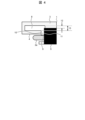
- FIG. 1 is a cross-sectional view of a motor according to an embodiment of the present invention
- Enlarged view of FIG. 1 is a circumferential overall view of a supply passage according to an embodiment of the present invention
- FIG. 1 is an explanatory diagram of a discharge passage according to an embodiment of the present invention.
- the motor 100 includes a rotor 14 and a stator.
- the rotor 14 and the stator are covered by a housing 1.
- the stator has a stator core 5 and a coil 2.
- the stator core 5 is formed in an annular shape in the circumferential direction and has a plurality of slots (not shown) in the circumferential direction, into which a coil 2 is inserted.
- a supply passage 8 for cooling the stator is formed in the axial direction.
- the coil 2 (FIG. 1) of the stator core 5 has coil ends 2a at both axial ends.
- the coil ends 2a protrude from both axial end faces of the stator core 5 to the outside of the stator core 5.
- the housing 1 has a first wall 3 and a second wall 4 provided on the inner peripheral side of the first wall 3.
- the supply passage 8 is a flow path for circulating a coolant that cools the motor 100, and is formed by the first wall 3 and the second wall 4 in the radial direction.
- the supply passage 8 is formed in a circumferential ring shape as shown in FIG. 3 described below.
- the supply passage 8 also extends in the axial direction on the outer periphery of the stator core 5 (see FIG. 1), allowing the refrigerant to be supplied to both axial sides of the stator core 5.
- the stator core 5 is fixed to the housing 1 by the fixing portion 6, and is positioned so as to erode a part of the supply passage 8 extending in the axial direction.
- the fixing portion 6 is, for example, a bolt, and is provided radially inward from the first wall 3. This allows the motor 100 to be made more compact.
- the supply path 8 has a shift portion 7 that aligns with the location of the fixed portion 6 in the circumferential direction. This allows the supply path 8 to be formed in the circumferential direction so as to avoid the fixed portion 6, making it possible to reduce the size.
- FIG. 3 shows the supply passage 8 formed in the circumferential direction of the rotating electric machine 100, but the flow passage provided in the axial direction on the outer periphery of the stator core 5 and the supply passage 8 formed on the opposite side of the stator core 5 in Fig. 2 are not shown. Also, the circumferential supply passage 8 is shown alone to clearly show its shape, but as described above, the supply passage 8 is actually a space formed between the first wall 3 and the second wall 4 inside the motor housing 1.
- the supply path 8 allows the coolant to flow through it to flow in through the coolant supply port 8a.
- the supply path 8 also has a shift section 7 that is shifted in the axial direction to avoid the fixed section 6 in accordance with the shape of the fixed section 6, thereby preventing the rotating electric machine 100 from expanding in the axial direction and contributing to miniaturization.
- the supply passage 8 has a discharge passage 9 extending radially inward.
- the discharge passage 9 is formed along the supply passage 8 extending circumferentially.
- the discharge passage 9 is provided vertically and radially inward with respect to the supply passage 8 extending axially, and the refrigerant is discharged to the coil end 2a provided radially inward of the discharge passage 9, thereby directly cooling the coil 2.
- the discharge passage 9 is formed by an open end 10, which is the end face of the second wall 4 that is formed to protrude toward the stator core 5, and a core end face 11, which is the end face of a portion of the stator core 5.
- the discharge passage 9 may also be formed in the shift section 7 ( Figures 2 and 3) in the supply passage 8 in a similar manner.
- the discharge passage 9 for directly cooling the coil 2 to improve heat dissipation efficiency, it is formed from the housing 1 (open end 10) and the stator core 5 (core end face 11), which eliminates the need to drill new holes in the housing 1 and contributes to improving the strength of the housing 1 and reducing costs.
- the discharge passage 9 can be designed with a high degree of freedom in the circumferential direction in areas other than the fixed portion 6.
- the first distance 12, which is the distance from the first wall 3 to the outer peripheral surface of the stator core 5, is smaller than the distance from the first wall 3 to the second distance 13, which is the radial size of the supply path 8. This contributes to the miniaturization of the motor 100.
- a rotating electric machine 100 having a stator and a rotor 14 and a housing 1 covering the stator and the rotor, the stator having an annular stator core 5 and a coil 2 inserted into the stator core 5 and having a coil end 2a protruding from an end face of the stator core 5 to the outside of the stator core 5.
- the housing 1 has an annular supply passage 8 formed by a first wall 3 and a second wall 4 provided radially inward from the first wall 3, and a discharge passage 9 that discharges a medium flowing through the supply passage 8 to the coil end 2a.
- the discharge passage 9 is formed in cross section by an open end 10, which is the end face of the second wall 4 protruding toward the stator core 5, and an end face 11 of the stator core 5.
- the discharge passage 9 is arranged vertically and radially inward with respect to the supply passage 8 which is arranged in the axial direction. This improves the cooling effect.
- the stator core 5 is provided with a fixed portion 6 that fixes the stator core 5 to the housing 1, and the supply passage 8 is provided with a shift portion 7 that is formed by shifting the supply passage 8 in the axial direction to avoid the fixed portion 6 in accordance with the shape of the fixed portion 6. This contributes to miniaturization.
- the present invention is not limited to the above-described embodiment, and various modifications and other configurations can be combined without departing from the spirit of the invention. Furthermore, the present invention is not limited to those having all of the configurations described in the above-described embodiment, and also includes those in which some of the configurations have been omitted.
Landscapes
- Engineering & Computer Science (AREA)
- Power Engineering (AREA)
- Motor Or Generator Cooling System (AREA)
- Motor Or Generator Frames (AREA)
- Iron Core Of Rotating Electric Machines (AREA)
Abstract
Description
(図1)
モータ100は、回転子14と固定子を備える。回転子14および固定子は、ハウジング1によって覆われている。固定子は、固定子コア5とコイル2を有する。固定子コア5は、周方向に環状に形成されかつ周方向に複数のスロット(図示せず)を有しており、各スロットにはコイル2が挿入されている。固定子コア5の外周側には、固定子を冷却するための供給路8が軸方向に形成されている。
固定子コア5が有するコイル2(図1)は、軸方向両端にコイルエンド2aを有している。コイルエンド2aは、固定子コア5の軸方向両端面から固定子コア5の外部に突出している。ハウジング1は、第1壁3と、第1壁3よりも内周側に設けられる第2壁4と、を有する。供給路8はモータ100を冷却する冷媒を流通させる流路であり、径方向において第1壁3と第2壁4によって形成される。
回転電機100の周方向に形成される供給路8について図3に図示したが、固定子コア5の外周側に軸方向に設けられる流路と、図2において固定子コア5の反対側に形成される供給路8とについては、図示を割愛している。また、周方向の供給路8は、形状を分かりやすく示すため、供給路8を単独で図示しているが、前述した通り、実際には供給路8はモータハウジング1の内部において第1壁3と第2壁4の間に形成される空間である。
供給路8は、径方向内側に向かって設けられている吐出路9を有している。吐出路9は、周方向に設けられている供給路8に沿って形成されている。吐出路9は、軸方向に設けられる供給路8に対して、鉛直方向かつ径方向内側に向かって設けられており、吐出路9の径方向内側に設けられているコイルエンド2aに対して冷媒を吐出させることで、コイル2の直接冷却を実現している。
2 コイル
2a コイルエンド
3 第1壁
4 第2壁
5 固定子コア
6 固定部
7 シフト部
8 供給路
8a 冷媒供給口
9 吐出路
10 解放端
11 コア端面
12 第1距離
13 第2距離
14 回転子
100 モータ
Claims (4)
- 固定子および回転子を有し、前記固定子および前記回転子を覆うハウジング、を備える回転電機であって、
前記固定子は、環状の固定子コアと、前記固定子コアに挿入されかつ前記固定子コアの端面から前記固定子コアの外部にコイルエンドを突出させるコイルと、を備え、
前記ハウジングは、第1壁と、前記第1壁より径方向内側に設けられる第2壁と、によって形成される環状の供給路と、前記供給路内を流通する媒体を前記コイルエンドに吐出する吐出路と、を備え、
前記吐出路は、断面上において、前記固定子コアに向かって突出する前記第2壁の端面である解放端と、前記固定子コアの端面と、によって形成される
回転電機。 - 請求項1に記載の回転電機であって、
径方向において、前記第1壁から前記固定子コアの外周面までの距離である第1距離は、前記第1壁から前記第2壁までの距離である第2距離より小さい
回転電機。 - 請求項1に記載の回転電機であって、
前記吐出路は、軸方向に設けられる前記供給路に対して、鉛直方向かつ径方向内側に向かって設けられる
回転電機。 - 請求項2に記載の回転電機であって、
前記固定子コアを前記ハウジングに固定する固定部を備え、
前記供給路は、前記固定部の形状に沿って前記固定部を避けるように軸方向にシフトして形成されるシフト部を備える
回転電機。
Priority Applications (3)
| Application Number | Priority Date | Filing Date | Title |
|---|---|---|---|
| JP2025529140A JPWO2025004288A1 (ja) | 2023-06-29 | 2023-06-29 | |
| CN202380094915.0A CN120826859A (zh) | 2023-06-29 | 2023-06-29 | 旋转电机 |
| PCT/JP2023/024271 WO2025004288A1 (ja) | 2023-06-29 | 2023-06-29 | 回転電機 |
Applications Claiming Priority (1)
| Application Number | Priority Date | Filing Date | Title |
|---|---|---|---|
| PCT/JP2023/024271 WO2025004288A1 (ja) | 2023-06-29 | 2023-06-29 | 回転電機 |
Publications (1)
| Publication Number | Publication Date |
|---|---|
| WO2025004288A1 true WO2025004288A1 (ja) | 2025-01-02 |
Family
ID=93938236
Family Applications (1)
| Application Number | Title | Priority Date | Filing Date |
|---|---|---|---|
| PCT/JP2023/024271 Ceased WO2025004288A1 (ja) | 2023-06-29 | 2023-06-29 | 回転電機 |
Country Status (3)
| Country | Link |
|---|---|
| JP (1) | JPWO2025004288A1 (ja) |
| CN (1) | CN120826859A (ja) |
| WO (1) | WO2025004288A1 (ja) |
Citations (6)
| Publication number | Priority date | Publication date | Assignee | Title |
|---|---|---|---|---|
| JP2001145302A (ja) * | 1999-11-17 | 2001-05-25 | Nissan Motor Co Ltd | モータの冷却装置 |
| JP2004208461A (ja) * | 2002-12-26 | 2004-07-22 | Nissan Motor Co Ltd | 回転電機の冷却構造 |
| JP2013141410A (ja) * | 2013-04-24 | 2013-07-18 | Hitachi Automotive Systems Ltd | 回転電機のステータ及びこれを用いた回転電機 |
| JP2017153309A (ja) * | 2016-02-26 | 2017-08-31 | Ntn株式会社 | 回転電動機の絶縁ボビン |
| CN109428422A (zh) * | 2017-08-31 | 2019-03-05 | 中车株洲电力机车研究所有限公司 | 一种电机绕组端部冷却装置及冷却系统 |
| WO2019053920A1 (ja) * | 2017-09-12 | 2019-03-21 | 三菱自動車工業株式会社 | 回転電機のステータ冷却構造 |
-
2023
- 2023-06-29 JP JP2025529140A patent/JPWO2025004288A1/ja active Pending
- 2023-06-29 WO PCT/JP2023/024271 patent/WO2025004288A1/ja not_active Ceased
- 2023-06-29 CN CN202380094915.0A patent/CN120826859A/zh active Pending
Patent Citations (6)
| Publication number | Priority date | Publication date | Assignee | Title |
|---|---|---|---|---|
| JP2001145302A (ja) * | 1999-11-17 | 2001-05-25 | Nissan Motor Co Ltd | モータの冷却装置 |
| JP2004208461A (ja) * | 2002-12-26 | 2004-07-22 | Nissan Motor Co Ltd | 回転電機の冷却構造 |
| JP2013141410A (ja) * | 2013-04-24 | 2013-07-18 | Hitachi Automotive Systems Ltd | 回転電機のステータ及びこれを用いた回転電機 |
| JP2017153309A (ja) * | 2016-02-26 | 2017-08-31 | Ntn株式会社 | 回転電動機の絶縁ボビン |
| CN109428422A (zh) * | 2017-08-31 | 2019-03-05 | 中车株洲电力机车研究所有限公司 | 一种电机绕组端部冷却装置及冷却系统 |
| WO2019053920A1 (ja) * | 2017-09-12 | 2019-03-21 | 三菱自動車工業株式会社 | 回転電機のステータ冷却構造 |
Also Published As
| Publication number | Publication date |
|---|---|
| JPWO2025004288A1 (ja) | 2025-01-02 |
| CN120826859A (zh) | 2025-10-21 |
Similar Documents
| Publication | Publication Date | Title |
|---|---|---|
| JP4082359B2 (ja) | 回転電機の冷却構造 | |
| JP5331521B2 (ja) | トロイダル巻線モータ | |
| CN1950986A (zh) | 带水冷却系统的电机 | |
| CN105048662A (zh) | 电机的散热 | |
| JP7483928B2 (ja) | 回転子、回転電機 | |
| US20210336510A1 (en) | Rotor end ring with oil jacket | |
| US20130342052A1 (en) | Electric machine with circumferential rotor and housing fins | |
| CN115378168A (zh) | 转子组件和包括其的电机 | |
| JP6212998B2 (ja) | 回転機および回転機の製造方法 | |
| JP2024118089A (ja) | 回転電機 | |
| JP4100170B2 (ja) | 回転電機の冷却構造 | |
| JP2019205254A (ja) | 回転電機 | |
| JP6984383B2 (ja) | 回転機械 | |
| CN118316215A (zh) | 定子铁芯、定子及电机 | |
| CN114189091A (zh) | 旋转电机 | |
| CN115603484B (zh) | 一种轴向磁场电机及定子冷却结构 | |
| JP7331625B2 (ja) | 回転電機 | |
| CN102959837B (zh) | 旋转电机的冷却构造 | |
| JP2019161861A (ja) | 回転電機 | |
| WO2025017963A1 (ja) | コイル、及び回転電機 | |
| JP7649204B2 (ja) | 回転電機用ケース、及び回転電機 | |
| JP6473128B2 (ja) | 同期回転電機および界磁巻線端部保持構造 | |
| CN120826859A (zh) | 旋转电机 | |
| JP2024118725A (ja) | 回転電機の冷却構造 | |
| CN119866590A (zh) | 用于电机的定子和电机 |
Legal Events
| Date | Code | Title | Description |
|---|---|---|---|
| 121 | Ep: the epo has been informed by wipo that ep was designated in this application |
Ref document number: 23943680 Country of ref document: EP Kind code of ref document: A1 |
|
| WWE | Wipo information: entry into national phase |
Ref document number: 202380094915.0 Country of ref document: CN |
|
| ENP | Entry into the national phase |
Ref document number: 2025529140 Country of ref document: JP Kind code of ref document: A |
|
| WWE | Wipo information: entry into national phase |
Ref document number: 2025529140 Country of ref document: JP |
|
| WWP | Wipo information: published in national office |
Ref document number: 202380094915.0 Country of ref document: CN |
|
| NENP | Non-entry into the national phase |
Ref country code: DE |
|
| 122 | Ep: pct application non-entry in european phase |
Ref document number: 23943680 Country of ref document: EP Kind code of ref document: A1 |