WO2025004253A1 - 吸気制御装置 - Google Patents
吸気制御装置 Download PDFInfo
- Publication number
- WO2025004253A1 WO2025004253A1 PCT/JP2023/024079 JP2023024079W WO2025004253A1 WO 2025004253 A1 WO2025004253 A1 WO 2025004253A1 JP 2023024079 W JP2023024079 W JP 2023024079W WO 2025004253 A1 WO2025004253 A1 WO 2025004253A1
- Authority
- WO
- WIPO (PCT)
- Prior art keywords
- band
- tube
- control device
- cylindrical portion
- intake control
- Prior art date
- Legal status (The legal status is an assumption and is not a legal conclusion. Google has not performed a legal analysis and makes no representation as to the accuracy of the status listed.)
- Ceased
Links
Images


Classifications
-
- F—MECHANICAL ENGINEERING; LIGHTING; HEATING; WEAPONS; BLASTING
- F02—COMBUSTION ENGINES; HOT-GAS OR COMBUSTION-PRODUCT ENGINE PLANTS
- F02D—CONTROLLING COMBUSTION ENGINES
- F02D9/00—Controlling engines by throttling air or fuel-and-air induction conduits or exhaust conduits
- F02D9/08—Throttle valves specially adapted therefor; Arrangements of such valves in conduits
- F02D9/10—Throttle valves specially adapted therefor; Arrangements of such valves in conduits having pivotally-mounted flaps
Definitions
- the present invention relates to an intake control device equipped with a throttle body.
- This protrusion is formed when the throttle body is molded.
- this protrusion cannot be formed using only the main mold, which moves in the direction in which the intake passage extends to mold the cylindrical portion. Therefore, to form this protrusion, a slide mold is used, which moves in a direction perpendicular to the direction in which the intake passage extends.
- the object of the present invention is to provide an intake control device that provides a tube prevention function at low cost.
- the band fixed to the band fixing part can reliably prevent the tube from coming out of the cylindrical part. Therefore, it is possible to provide an intake control device that does not require the formation of a protrusion or additional machining of an annular groove on the cylindrical part of the throttle body, which was previously required to prevent the tube from coming out, and that inexpensively achieves the function of preventing the tube from coming out.
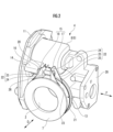
- FIG. 1 shows the main parts of an intake control device according to a first embodiment of the present invention.
- this intake control device 1 comprises a throttle body 4 having a cylindrical portion 3 in which an intake passage 2 is formed, a throttle valve 5 that opens and closes the intake passage 2, and a throttle shaft 6 that holds the throttle valve 5 and is rotatably supported by the throttle body 4.
- a tube 7 (see FIG. 2), such as an air duct leading to an air cleaner, is connected to the cylindrical portion 3.
- the throttle body 4 includes a motor case 9 that houses a motor 8, and a gear chamber 11 that houses a gear mechanism 10 (see FIG. 5) that transmits the rotation of the drive shaft of the motor 8 to the throttle shaft 6.
- the motor 8 supplies power to open and close the throttle valve 5 via the gear mechanism 10.
- the gear chamber 11 is closed by a gear chamber cover 12.
- the throttle body 4 also includes a band fixing portion 14 to which a metal band 13 (see FIG. 2) is fixed, which tightens the outer periphery of the tube 7 connected to the cylindrical portion 3 against the cylindrical portion 3.
- the band fixing portion 14 is fixed to the surface of the motor case 9 so as to extend from the surface. More specifically, the band fixing portion 14 is provided so as to protrude from the side wall of the motor case 9 along the passage direction D, which is the direction in which the intake passage 2 (the central axis) extends.
- Figure 2 shows the tube 7 attached to the throttle body 4. However, in Figure 2, only the end of the tube 7 that is connected to the cylindrical body portion 3 is shown. As shown in Figure 2, the band fixing portion 14 has an insertion hole 16 through which a connecting member 15 that connects the ends of the band 13 is passed.
- a bolt 17 and a nut 18 are used as the connecting member 15.
- the tip of the bolt 17 is passed through the insertion hole 16, and a female thread 19 (see Figure 1) is provided for screwing the tip.
- the band fixing part 14 has an opening for the insertion hole 16 and is provided with a seat 20 with which the bolt 17 of the connecting member 15 can come into contact.
- the seat 20 is aligned along the passage direction D.
- the tube 7 has an annular groove 21 on the outer periphery of the end connected to the cylindrical body 3, into which the band 13 is placed when the band 13 tightens the outer periphery of the tube 7.
- the band 13 has fastening portions 22 at both ends for fastening the outer periphery of the tube 7 with the band 13 placed in the groove 21.
- Each fastening portion 22 has opposing plates 24 that rise outward from both opposing edges of the band body 23, and fixing plates 25 that fix each opposing plate 24 to each edge of the band body 23.
- Each opposing plate 24 is fixed to the band body 23 in a mutually opposing orientation.
- Each opposing plate 24 is provided with a through hole 26 through which the above-mentioned bolt 17 is passed.
- Two fixing plates 25 are provided on each opposing plate 24.
- Each fixing plate 25 has a shape similar to a right triangle, and one of the two sides other than the hypotenuse is fixed to the side edge of the corresponding opposing plate 24, and the other side is fixed to the corresponding side edge of the band body 23.
- Each fastening portion 22 is fixed to the band body 23 via two fixing plates 25 so that, when the band 13 is fastening the outer circumference of the tube 7, the opposing plates 24 of each fastening portion 22 face each other in parallel with a fastening distance d between them.
- the throttle body 4 has a unit connection part 28 at one end in the shaft direction F, which is the direction in which the throttle shaft 6 extends, that connects to a sensor unit 27 (see FIG. 1).
- the sensor unit 27 has at least one of an opening sensor that detects the opening of the throttle valve 5, an intake air pressure sensor that detects the pressure of the intake air in the intake passage 2, and an intake air temperature sensor that detects the temperature of the intake air in the intake passage 2.
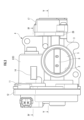
- Figure 3 shows the intake control device 1 as viewed from the side where the tube 7 is connected along the passage direction D.
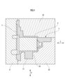
- Figure 4 shows the relationship between the throttle body 4 and the mold when molding the throttle body 4, in a cross section taken along the plane corresponding to line IV-IV in Figure 3.
- the band fixing portion 14 side of the motor case 9 is molded using a first main mold 29
- the side of the motor case 9 opposite the band fixing portion 14 is molded using a second main mold 30
- the gear chamber 11 side is molded using a slide mold 31.
- the first main mold 29 moving in the passage direction D molds the cylindrical portion 3 and the intake passage 2 therein, and also molds the band fixing portion 14 together with its seat surface 20.
- the periphery of the cylindrical portion 3 is molded only by the first main mold 29 moving in the passage direction D and the second main mold 30 moving in the passage direction D.
- the slide mold 31 moves in a direction parallel to the drive shaft of the motor 8 (shaft direction F) and molds the inside of the motor case 9 together with the gear chamber 11.
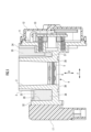
- Figure 5 is a cross-sectional view taken along line V-V in Figure 3, and shows the periphery of the cylindrical portion 3 molded by the first main mold 29 and the second main mold 30.
- the first main mold 29 molds a first recess 33 between the unit connection portion 28 and the cylindrical portion 3, which is recessed from the end 32 where the tube 7 of the unit connection portion 28 connects to the cylindrical portion 3 toward the other end along the passage direction D, between the unit connection portion 28 and the cylindrical portion 3.
- a second recess 35 is formed between the gear chamber 11 and the cylindrical portion 3 along the passage direction D, recessed from the end 34 on the side where the tube 7 of the gear chamber 11 connects to the cylindrical portion 3 toward the other end.
- a throttle body 4 with little excess material is formed, having the first recess 33 and the second recess 35.
- the cross sections of the first recess 33 and the second recess 35 parallel to both the passage direction D and the shaft direction F can have various values of cross-sectional area that differ depending on the position of the cross section in the direction perpendicular to both directions.
- the cross sections of the first recess 33 and the second recess 35 at the line V-V cross section, which is one of these cross sections, are shown as the shaded areas 36 and 37, respectively.
- first recess 33 and the second recess 35 have portions that extend along the passage direction D from the end 32 or 34 on the side where the unit connection portion 28 or the gear chamber 11 tube 7 is connected to the vicinity of the end 38 on the opposite side to the side where the tube 7 is connected to the cylindrical portion 3.
- the cross sections of the portions of the first recess 33 and the second recess 35 that extend to the vicinity of the opposite end 38 are shown as the shaded portions 36 and 37, respectively.
- the bolt 17 is passed through the through-holes 26 of both tightening portions 22, and the nut 18 is screwed onto the tip side of the bolt 17. Furthermore, the tip side of the bolt 17 beyond the nut 18 is passed through the insertion hole 16 of the band fixing portion 14 and screwed into its female thread 19. The amount of screwing and the amount of screwing of the nut 18 are then adjusted so that the tightening force of the band 13 on the tube 7 to the cylindrical portion 3 is appropriate, and so that both tightening portions 22 are securely fixed to the band fixing portion 14.
- the throttle body 4 is provided with a band fixing portion 14 to which a band 13 is fixed, which tightens the outer periphery of the tube 7 connected to the cylindrical portion 3 against the cylindrical portion 3. This makes it possible to reliably achieve the function of the band 13 to prevent the tube 7 from coming loose, while eliminating the need for the protrusions or annular grooves that were previously required on the outer periphery of the cylindrical portion 3 of the throttle body 4.
- the tube 7 can be prevented from falling out at low cost.
- the band 13 is fixed to the throttle body 4, the band 13 will not come off the cylindrical portion 3 of the throttle body 4. Therefore, compared to the conventional technology in which the tube 7 is prevented from coming off by pressing the tube 7 against a protrusion or annular groove of the throttle body 4, the tube 7, which is fastened and prevented from coming off by the band 13, can be more reliably prevented from coming off.
- the band fixing portion 14 is provided with an insertion hole 16 through which a connecting member 15 that connects the ends of the band 13 is passed.
- the band 13 can be fixed to the throttle body 4 by the connecting member 15 using this insertion hole 16. Therefore, when fixing the band 13 to the throttle body 4, no additional parts other than the connecting member 15 are required.
- machining the insertion hole 16 in the band fixing part 14 is easier than forming a protrusion around the cylindrical part 3 using a slide mold or forming an annular groove by machining. Therefore, the function of preventing the tube from falling out can be reliably achieved at low cost.
- the band 13 is fixed to the throttle body 4 using the bolts 17 and nuts 18 that have traditionally been used as the connecting members 15, there is no need to prepare special members for this fixing. Therefore, the function of preventing the tube 7 from falling out can be achieved more inexpensively.
- the through hole 16 of the band fixing portion 14 is provided with a female thread 19 for screwing in the bolt 17, which eliminates the need for screw holes that were previously required at the ends of the band to join the ends of the band 13. This allows the band 13 to be manufactured at low cost.
- the band fixing portion 14 has an insertion hole 16 that opens and a seating surface 20 that contacts the band 13, which is aligned along the passage direction D. Therefore, when molding the throttle body 4, the intake passage 2 is molded and the seating surface 20 can be formed by the first main mold 29 that moves in the passage direction D.
- a slide mold that moves in a direction perpendicular to the extension direction of the intake passage 2 is not required to mold the band fixing portion 14 equipped with the seat surface 20. This reduces mold costs and improves productivity, making it possible to realize a more reliable and inexpensive mechanism for preventing the tube 7 from coming loose.
- first recess 33 and the second recess 35 are formed between the unit connection portion 28 and the gear chamber 11 and the cylindrical portion 3, so that a throttle body 4 with less excess material can be formed compared to conventional throttle bodies that use protrusions and annular grooves to prevent the tube 7 from coming loose.
- the periphery of the cylindrical portion 3 is molded using a slide mold that moves in a direction perpendicular to the passage direction D in order to form the protrusions and annular grooves.
- the first recess 33 and the second recess 35 can be molded between the unit connection portion 28 and the cylindrical portion 3 and between the gear chamber 11 and the cylindrical portion 3 using only the first main mold 29 that moves in the direction in which the intake passage 2 extends. This makes it possible to mold a throttle body 4 with little excess material and provided with the first recess 33 and the second recess 35.
- the end 32 or 34 of the unit connection part 28 or the gear chamber 11 to which the tube 7 is connected extends to the end of the cylindrical part 3 to which the tube 7 is connected.
- the band fixing portion 14 extends from the surface of the motor case 9, the band fixing portion 14 functions as a heat dissipation fin, and the amount of heat dissipated by the motor 8 can be increased. This makes it possible to prevent the motor 8 from becoming too hot, maintain its output, and improve its durability.
- FIG. 6 shows the throttle body of an intake control device according to a second embodiment of the present invention.
- This throttle body 4b is provided with a band fixing portion 14b instead of the band fixing portion 14 in the first embodiment.
- the band fixing portion 14b is provided on the side of the motor 8, protruding in a direction parallel to the passage direction D toward the side where the tube 7 of the intake passage 2 is connected. In this respect, it is similar to the band fixing portion 14 of the first embodiment.
- the band fixing portion 14b is also similar to the band fixing portion 14 of the first embodiment in that it is used to fix the band 13 that tightens the outer periphery of the tube 7 connected to the cylindrical portion 3 against the cylindrical portion 3.
- band fixing portion 14b differs from band fixing portion 14 of the first embodiment in that it is provided at a position farther away from gear chamber 11 than band fixing portion 14 of the first embodiment.
- band fixing portion 14b is provided at a position on a plane that is substantially perpendicular to the central axis of motor 8 and includes the central axis of intake passage 2.
- the band fixing portion 14b is provided with a through hole 39 as an insertion hole for passing the bolt 17b along the shaft direction F.
- the bolt 17b and the nut 18b screwed onto it constitute a connecting member 15b that connects the ends of the band 13 together.
- Opposing surfaces 40 are provided on both end faces of the band fixing portion 14b in the direction along the through hole 39, which face the opposing plates 24 of the tightening portions 22 on both ends of the band 13.
- a small gap is created between the opposing plate 24 at at least one end of the band 13 and the corresponding opposing surface 40.
- Each opposing surface 40 is aligned along the passage direction D and functions as a seat that can come into contact with the corresponding opposing plate 24 of the fastening portion 22 of the band 13.
- the other configurations of the throttle body 4b of this embodiment are the same as those of the first embodiment.
- the amount of screwing is adjusted so that the clamping force of the band 13 on the tube 7 to the cylindrical portion 3 is appropriate.
- a small gap is created between the opposing plate 24 and the opposing surface 40 at least on one end of the band 13, so that the clamping force can be appropriately adjusted.
- connection side end of the tube 7 is securely fixed to the end of the cylindrical portion 3 by the band 13, and the band 13 is fixed to the throttle body 4b via the band fixing portion 14b. This completes the connection of the tube 7 to the cylindrical portion 3.
- the band fixing portion 14b is located between the fastening portions 22 at both ends of the band 13, which provides a space advantage. In other respects, the same effects as the first embodiment are achieved.
- the connecting member 15 that connects the ends of the band 13 together is not limited to a combination of the bolt 17 and nut 18, but may be only the bolt 17.
- one fastening portion 22 of the band 13 is configured so as to be supported by the seat surface 20 of the band fixing portion 14, and the one fastening portion 22 is brought into contact with the seat surface 20. Then, the bolt 17 is passed from the other fastening portion 22 side up to the insertion hole 16 of the band fixing portion 14 and screwed into the female thread 19 of the band fixing portion 14. This joins both ends of the band 13 together and fixes the band 13 to the throttle body 4. This allows the nut 18 to be omitted.
- 1...intake control device 2...intake passage, 3...body portion, 4, 4b...throttle body, 5...throttle valve, 6...throttle shaft, 7...tube, 8...motor, 9...motor case, 10...gear mechanism, 11...gear chamber, 12...gear chamber cover, 13...band, 14, 14b...band fixing portion, 15, 15b...connecting member, 16...insertion hole, 17, 17b...bolt, 18, 18b...nut , 19... female thread, 20... seat surface, 21... groove, 22... fastening portion, 23... band body, 24... opposing plate, 25... fixing plate, 26... through hole, 27... sensor unit, 28... unit connection portion, 29... first main mold, 30... second main mold, 31... slide mold, 32... end, 33... first recess, 34... end, 35... second recess, 36... shaded portion, 37... shaded portion, 38... end, 39... through hole, 40... opposing surface.
Landscapes
- Engineering & Computer Science (AREA)
- Chemical & Material Sciences (AREA)
- Combustion & Propulsion (AREA)
- Mechanical Engineering (AREA)
- General Engineering & Computer Science (AREA)
- Control Of Throttle Valves Provided In The Intake System Or In The Exhaust System (AREA)
Abstract
Description
Claims (8)
- 吸気通路が内部に形成された円胴部を有するスロットルボディと、
前記吸気通路を開閉するスロットルバルブと、
前記スロットルバルブを保持し、前記スロットルボディにより回転可能に支持されるスロットルシャフトとを備え、
前記円胴部にチューブが接続される吸気制御装置において、
前記スロットルボディは、前記円胴部に接続される前記チューブの外周を該円胴部に対して締め付けるバンドが固定されるバンド固定部を備えることを特徴とする吸気制御装置。 - 前記バンド固定部には、前記バンドの端部同士を結合する結合部材が通される挿通孔が設けられることを特徴とする請求項1に記載の吸気制御装置。
- 前記結合部材は、ボルトを用いて構成されることを特徴とする請求項2に記載の吸気制御装置。
- 前記挿通孔には、前記ボルトを螺合するための雌ねじが設けられることを特徴とする請求項3に記載の吸気制御装置。
- 前記バンド固定部は、前記挿通孔が開口し、前記バンド又は前記結合部材が接触し又は接触し得る座面を備え、該座面は、前記吸気通路が延びる通路方向に沿っていることを特徴とする請求項2に記載の吸気制御装置。
- 前記スロットルボディは、前記スロットルシャフトが延びる方向の一方の端部に、開度センサ、吸気圧センサ、及び吸気温センサのうちの少なくとも1つを有するセンサユニットに接続するユニット接続部、又は、モータの回転を前記スロットルシャフトに伝達するギア機構を収容するギア室を備え、
前記ユニット接続部と前記円胴部との間に、前記通路方向に沿って該ユニット接続部の前記チューブが該円胴部に接続する側の端から他端側に凹んだ第1凹部が形成され、又は、前記ギア室と該円胴部との間に、前記通路方向に沿って該ギア室の該チューブが該円胴部に接続する側の端から他端側に凹んだ第2凹部が形成されることを特徴とする請求項5に記載の吸気制御装置。 - 前記通路方向に沿って、前記ユニット接続部又は前記ギア室の前記チューブが接続する側の端は、前記円胴部の前記チューブが接続する側の端まで延びていることを特徴とする請求項6に記載の吸気制御装置。
- 前記スロットルバルブを開閉する動力を供給するモータを備え、前記スロットルボディは、該モータを収容するモータケースを備え、前記バンド固定部は、該モータケースの表面から延びていることを特徴とする請求項1に記載の吸気制御装置。
Priority Applications (3)
| Application Number | Priority Date | Filing Date | Title |
|---|---|---|---|
| JP2025529110A JP7880012B2 (ja) | 2023-06-28 | 2023-06-28 | 吸気制御装置 |
| CN202380096627.9A CN121039379A (zh) | 2023-06-28 | 2023-06-28 | 进气控制装置 |
| PCT/JP2023/024079 WO2025004253A1 (ja) | 2023-06-28 | 2023-06-28 | 吸気制御装置 |
Applications Claiming Priority (1)
| Application Number | Priority Date | Filing Date | Title |
|---|---|---|---|
| PCT/JP2023/024079 WO2025004253A1 (ja) | 2023-06-28 | 2023-06-28 | 吸気制御装置 |
Publications (1)
| Publication Number | Publication Date |
|---|---|
| WO2025004253A1 true WO2025004253A1 (ja) | 2025-01-02 |
Family
ID=93937988
Family Applications (1)
| Application Number | Title | Priority Date | Filing Date |
|---|---|---|---|
| PCT/JP2023/024079 Ceased WO2025004253A1 (ja) | 2023-06-28 | 2023-06-28 | 吸気制御装置 |
Country Status (3)
| Country | Link |
|---|---|
| JP (1) | JP7880012B2 (ja) |
| CN (1) | CN121039379A (ja) |
| WO (1) | WO2025004253A1 (ja) |
Citations (7)
| Publication number | Priority date | Publication date | Assignee | Title |
|---|---|---|---|---|
| JPS51151242U (ja) * | 1975-05-28 | 1976-12-03 | ||
| JPS55126084U (ja) * | 1979-02-28 | 1980-09-06 | ||
| JPH0332288U (ja) * | 1989-08-08 | 1991-03-28 | ||
| JPH04157285A (ja) * | 1990-10-18 | 1992-05-29 | Toyoda Gosei Co Ltd | クランプ付ホース |
| JP2008248824A (ja) * | 2007-03-30 | 2008-10-16 | Denso Corp | 電子スロットル |
| JP2013060844A (ja) * | 2011-09-13 | 2013-04-04 | Aisan Industry Co Ltd | 内燃機関の吸気装置 |
| JP2022135153A (ja) * | 2021-03-04 | 2022-09-15 | 日立Astemo株式会社 | 吸気制御装置 |
-
2023
- 2023-06-28 WO PCT/JP2023/024079 patent/WO2025004253A1/ja not_active Ceased
- 2023-06-28 JP JP2025529110A patent/JP7880012B2/ja active Active
- 2023-06-28 CN CN202380096627.9A patent/CN121039379A/zh active Pending
Patent Citations (7)
| Publication number | Priority date | Publication date | Assignee | Title |
|---|---|---|---|---|
| JPS51151242U (ja) * | 1975-05-28 | 1976-12-03 | ||
| JPS55126084U (ja) * | 1979-02-28 | 1980-09-06 | ||
| JPH0332288U (ja) * | 1989-08-08 | 1991-03-28 | ||
| JPH04157285A (ja) * | 1990-10-18 | 1992-05-29 | Toyoda Gosei Co Ltd | クランプ付ホース |
| JP2008248824A (ja) * | 2007-03-30 | 2008-10-16 | Denso Corp | 電子スロットル |
| JP2013060844A (ja) * | 2011-09-13 | 2013-04-04 | Aisan Industry Co Ltd | 内燃機関の吸気装置 |
| JP2022135153A (ja) * | 2021-03-04 | 2022-09-15 | 日立Astemo株式会社 | 吸気制御装置 |
Also Published As
| Publication number | Publication date |
|---|---|
| JP7880012B2 (ja) | 2026-06-24 |
| CN121039379A (zh) | 2025-11-28 |
| JPWO2025004253A1 (ja) | 2025-01-02 |
Similar Documents
| Publication | Publication Date | Title |
|---|---|---|
| EP0515436B1 (en) | Engine throttle blade sealing | |
| EP0947681B1 (en) | Clamshell throttle valve assembly | |
| EP1035355B1 (en) | Rotation stop device | |
| US20080110286A1 (en) | Ball screw device | |
| CN102242675B (zh) | 凸缘的紧固结构 | |
| JPH03540B2 (ja) | ||
| JP6332261B2 (ja) | 軸受支持装置 | |
| JPS60159007A (ja) | 2本スクリユ−シヤフト機械のハウジング部 | |
| US7600941B2 (en) | Shaft clamping mechanism | |
| JP4174800B2 (ja) | ソレノイドバルブ、及びその取付固定方法、並びにソレノイドバルブ、センサ、ポテンショメータ、流量センサその他の付属部品を取付固定するための部品取付固定具 | |
| JPH0359286B2 (ja) | ||
| WO2018235589A1 (ja) | 車両搭載機器のハウジング | |
| JP7291614B2 (ja) | リミットキャップ | |
| US6871631B2 (en) | Throttle valve body | |
| JP2004505194A (ja) | 内燃機関のガス交換弁と弁駆動体との同軸的に相前後して配置された2つのシャフトエンドの間の結合部 | |
| CN121039379A (zh) | 进气控制装置 | |
| JP2024126586A (ja) | 締結部材用の取付部材 | |
| JP7851813B2 (ja) | 流量調整制限部材 | |
| JP6909704B2 (ja) | 流体制御弁 | |
| KR101067015B1 (ko) | 다이캐스팅 금형 | |
| JPH0425657A (ja) | ウオームギヤのバックラッシュ除去装置 | |
| JP3308469B2 (ja) | 弁 | |
| US7390139B2 (en) | Boss assembly for threaded coupling | |
| JP4216841B2 (ja) | ジョイントブーツ | |
| JP2024013649A (ja) | 燃料調整機構 |
Legal Events
| Date | Code | Title | Description |
|---|---|---|---|
| 121 | Ep: the epo has been informed by wipo that ep was designated in this application |
Ref document number: 23943649 Country of ref document: EP Kind code of ref document: A1 |
|
| ENP | Entry into the national phase |
Ref document number: 2025529110 Country of ref document: JP Kind code of ref document: A |
|
| WWE | Wipo information: entry into national phase |
Ref document number: 2025529110 Country of ref document: JP |
|
| WWE | Wipo information: entry into national phase |
Ref document number: 2501006435 Country of ref document: TH |
|
| WWE | Wipo information: entry into national phase |
Ref document number: 202547093339 Country of ref document: IN |
|
| WWP | Wipo information: published in national office |
Ref document number: 202547093339 Country of ref document: IN |
|
| NENP | Non-entry into the national phase |
Ref country code: DE |
|
| 122 | Ep: pct application non-entry in european phase |
Ref document number: 23943649 Country of ref document: EP Kind code of ref document: A1 |