WO2025004146A1 - ブレーキ制御装置およびブレーキ制御方法 - Google Patents
ブレーキ制御装置およびブレーキ制御方法 Download PDFInfo
- Publication number
- WO2025004146A1 WO2025004146A1 PCT/JP2023/023616 JP2023023616W WO2025004146A1 WO 2025004146 A1 WO2025004146 A1 WO 2025004146A1 JP 2023023616 W JP2023023616 W JP 2023023616W WO 2025004146 A1 WO2025004146 A1 WO 2025004146A1
- Authority
- WO
- WIPO (PCT)
- Prior art keywords
- brake
- tread
- railway vehicle
- control device
- information
- Prior art date
- Legal status (The legal status is an assumption and is not a legal conclusion. Google has not performed a legal analysis and makes no representation as to the accuracy of the status listed.)
- Ceased
Links
Images



Classifications
-
- B—PERFORMING OPERATIONS; TRANSPORTING
- B60—VEHICLES IN GENERAL
- B60L—PROPULSION OF ELECTRICALLY-PROPELLED VEHICLES; SUPPLYING ELECTRIC POWER FOR AUXILIARY EQUIPMENT OF ELECTRICALLY-PROPELLED VEHICLES; ELECTRODYNAMIC BRAKE SYSTEMS FOR VEHICLES IN GENERAL; MAGNETIC SUSPENSION OR LEVITATION FOR VEHICLES; MONITORING OPERATING VARIABLES OF ELECTRICALLY-PROPELLED VEHICLES; ELECTRIC SAFETY DEVICES FOR ELECTRICALLY-PROPELLED VEHICLES
- B60L7/00—Electrodynamic brake systems for vehicles in general
- B60L7/24—Electrodynamic brake systems for vehicles in general with additional mechanical or electromagnetic braking
-
- B—PERFORMING OPERATIONS; TRANSPORTING
- B60—VEHICLES IN GENERAL
- B60T—VEHICLE BRAKE CONTROL SYSTEMS OR PARTS THEREOF; BRAKE CONTROL SYSTEMS OR PARTS THEREOF, IN GENERAL; ARRANGEMENT OF BRAKING ELEMENTS ON VEHICLES IN GENERAL; PORTABLE DEVICES FOR PREVENTING UNWANTED MOVEMENT OF VEHICLES; VEHICLE MODIFICATIONS TO FACILITATE COOLING OF BRAKES
- B60T8/00—Arrangements for adjusting wheel-braking force to meet varying vehicular or ground-surface conditions, e.g. limiting or varying distribution of braking force
- B60T8/17—Using electrical or electronic regulation means to control braking
Definitions
- This disclosure relates to a brake control device and brake control method installed in a railway vehicle.
- Patent Document 1 discloses a technology in which, when an air brake device mounted on a railway vehicle receives a zero thrust command, it applies an initial pressure to the brake pads, which is an air pressure that does not generate actual torque, and causes the brake pads to come into slight contact with the wheel tread. By keeping the brake pads in slight contact with the wheel tread, the air brake device described in Patent Document 1 can press the brake pads against the wheel tread without delay to generate braking force.
- the air brake device described in Patent Document 1 has brake pads that are in slight contact with the wheel tread while the railcar is traveling, causing the wheel tread to become mirror-finished by the brake pads.
- the condition of the track on which the railcar is traveling changes and skidding becomes more likely to occur, this can lead to an increase in the braking distance.
- the present disclosure has been made in consideration of the above, and aims to obtain a brake control device that can prevent the wheels of a railway vehicle from becoming mirror-finished and can prevent the braking distance from increasing in situations where the condition of the track on which the railway vehicle travels changes and skids become more likely to occur.
- the present disclosure provides a brake control device that controls the use of tread brakes, which generate braking force by pressing brake shoes against wheels, and regenerative brakes as brakes for railway vehicles.
- the brake control device is characterized by comprising: an acquisition unit that acquires position information of the railway vehicle; and a control unit that changes the brake use conditions to give priority to the use of regenerative brakes over tread brakes based on the position information, skid information indicating skid positions where the wheels may skid on the track on which the railway vehicle runs, and brake information indicating the braking positions at which the railway vehicle applies the brakes; and, when a brake command is acquired when the brake use conditions have been changed, uses the tread brakes at a specified ratio relative to the braking force required by the brake command to roughen the wheel tread with the brake shoes.
- the brake control device disclosed herein has the effect of preventing the wheels of a railway vehicle from becoming mirror-like, and preventing the braking distance from increasing in situations where the condition of the track on which the railway vehicle travels changes and skids become more likely to occur.
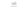
- FIG. 1 is a diagram showing a configuration example of a brake control system including a brake control device according to a first embodiment
- FIG. 2 is a diagram showing an example of a slide position indicated by slide information and a brake position indicated by brake information stored in a storage unit of the brake control device according to the first embodiment
- FIG. 2 is a diagram showing the control contents of the brake control device according to the first embodiment.
- FIG. 1 is a diagram showing an example of a case where a processing circuit included in the brake control system according to the first embodiment is configured with a processor and a memory.
- FIG. 1 is a diagram showing an example in which a processing circuit included in the brake control system according to the first embodiment is configured with dedicated hardware.
- FIG. 1 is a diagram showing a configuration example of a brake control system including a brake control device according to a first embodiment
- FIG. 2 is a diagram showing an example of a slide position indicated by slide information and a brake
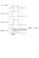
- FIG. 1 is a first diagram showing an example of a ratio of regenerative braking and tread braking used with respect to a required braking force in a brake control device according to a second embodiment
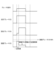
- FIG. 2 is a second diagram showing an example of a ratio of regenerative braking and tread braking used with respect to a required braking force by the brake control device according to the second embodiment
- FIG. 3 is a third diagram showing an example of a ratio of regenerative braking and tread braking used with respect to a required braking force by the brake control device according to the second embodiment.
- an air brake that uses air pressure as a pressure medium to activate a tread brake will be described as an example, but in this disclosure, the operating mechanism is not limited to this as long as it is a tread brake that presses the brake shoe against the wheel tread.
- the operating mechanism that presses the brake shoe against the wheel tread may be a tread brake that does not use a pressure medium and is powered by, for example, a motor or an electric actuator.
- Embodiment 1. 1 is a diagram showing an example of the configuration of a brake control system 30 including a brake control device 4 according to the first embodiment.
- the brake control system 30 is a system that is mounted on a railway vehicle 100 and is capable of using a regenerative brake controlled by a regenerative brake control unit 5 and a tread brake 6 as brakes for the railway vehicle 100.
- the brake control system 30 includes a brake command unit 1, a load compensation device 2, a speed sensor 3, a brake control device 4, a regenerative brake control unit 5, a tread brake 6, a vehicle information management device 7, and wheels 13.
- the railway vehicle 100 is actually equipped with a plurality of speed sensors 3, brake control devices 4, tread brakes 6, and wheels 13.
- some of the configuration such as the brake command unit 1 may be mounted only on specific railway vehicles 100, such as the leading and trailing cars of the train.
- the brake command unit 1 is installed in the driver's cab (not shown) of the railway vehicle 100, receives operations from the driver, etc., generates a brake command 1A according to the received operation content, and outputs it to the brake control device 4.
- the load compensation device 2 uses an air spring pressure sensor (not shown) or the like to generate a load compensation signal 2A indicating the pressure applied to the railway vehicle 100 by passengers or the like, and outputs the signal to the brake control device 4.
- the speed sensor 3 is a sensor that generates a speed signal 3A indicating the speed of the railway vehicle 100 based on the rotational speed of the wheels 13 and outputs the signal to the brake control device 4. Although omitted in FIG. 1, the speed sensor 3 is installed on the front and rear bogies of the railway vehicle 100, and the railway vehicle 100 is capable of detecting the speed from each wheel 13.
- the regenerative brake control unit 5 calculates the actual regenerative braking force according to the actual torque based on the regenerative pattern signal 4A obtained from the brake control unit 4, and controls the regenerative braking by a drive unit (not shown) or the like.
- the regenerative brake control unit 5 generates a regenerative feedback signal 5A indicating the actual regenerative braking force, which is the actual regenerative braking force, and outputs it to the brake control unit 4.
- the tread brake 6 generates a braking force by pressing the brake shoe 12 against the wheel 13 based on the pressure control signal 4B obtained from the brake control device 4.
- the tread brake 6 also comprises an electro-pneumatic converter valve, a main air tank, a relay valve, a pressure sensor, a brake cylinder, etc., but as these are general configurations, detailed explanations of each component will be omitted.
- the tread brake 6 generates a tread feedback signal 6A, such as the AC (Air Control) pressure, which is the air signal command pressure of the electro-pneumatic converter valve, and the BC (Brake Cylinder) pressure, which is the brake cylinder pressure of the relay valve, and outputs it to the brake control device 4.
- AC Air Control
- BC Brake Cylinder
- the vehicle information management device 7 manages the powering and braking of the railway vehicle 100 on a train-to-train basis, and manages various on-board equipment.
- the vehicle information management device 7 is, for example, a Train Information Management System (TIMS).
- TIS Train Information Management System
- the vehicle information management device 7 outputs position information 7A of the railway vehicle 100 obtained through normal management to the brake control device 4.
- the brake control device 4 controls the use of the tread brakes 6, which generate braking force by pressing the brake shoes 12 against the wheels 13, and the regenerative brakes via the regenerative brake control unit 5, as brakes for the railway vehicle 100.
- the brake control device 4 generates braking force in the railway vehicle 100 by regenerative braking using a drive device (not shown) via the regenerative brake control unit 5.
- the brake control device 4 also controls the tread brakes 6 in the railway vehicle 100, causing the tread brakes 6 to press the brake shoes 12 against the wheels 13 and generate braking force.
- the control of the regenerative brakes in the brake control device 4 via the regenerative brake control unit 5 includes, for example, control to apply the regenerative brakes and control to release the regenerative brakes.
- the control of the tread brakes 6 in the brake control device 4 includes, for example, control to apply the tread brakes 6 and control to release the tread brakes 6.
- the control to apply the regenerative brakes and the tread brakes 6 is control to decelerate the railway vehicle 100, that is, control to apply the brakes.
- the control to release the regenerative brakes and the tread brakes 6 is a control that allows the speed of the railway vehicle 100 to increase, that is, a so-called brake release control.
- the brake control device 4 includes an acquisition unit 41, a control unit 42, and a storage unit 43.
- the acquisition unit 41 acquires the brake command 1A from the brake command unit 1, the load adaptive signal 2A from the load adaptive device 2, the speed signal 3A from the speed sensor 3, and the position information 7A from the vehicle information management device 7.
- the acquisition unit 41 also acquires the regenerative feedback signal 5A from the regenerative brake control unit 5, and the tread feedback signal 6A from the tread brake 6.
- the acquisition unit 41 outputs the acquired commands, signals, information, etc. to the control unit 42.
- the acquisition unit 41 may obtain the position information 7A of the railway vehicle 100 by accumulating the travel distance of the railway vehicle 100 from a specified point that can be calculated using the speed signal 3A acquired from the speed sensor 3, rather than acquiring it from the vehicle information management device 7.
- the memory unit 43 stores slide information indicating slide positions where the wheels 13 may slide on the track on which the railcar 100 runs, and stores braking information indicating braking positions at which the railcar 100 applies the brakes.
- the slide position is, for example, the position where the railcar 100's running section switches from underground to above ground.
- the braking position is, for example, information indicating the position of a station where the railcar 100 will stop.
- the memory unit 43 may store the slide information and braking information in advance before the railcar 100 starts operating, by operation of a maintenance person of the railroad operator that operates the railcar 100, or may obtain and store the information from an external device, such as the vehicle information management device 7.
- FIG. 2 is a diagram showing an example of the slide position indicated by the slide information and the brake position indicated by the brake information stored in the memory unit 43 of the brake control device 4 in embodiment 1.
- the slide position indicated by the slide information is the position where the running section of the railway vehicle 100 switches from underground to above ground.
- the brake position indicated by the brake information is information indicating the position of the station where the railway vehicle 100 stops.
- the railway vehicle 100 is not affected by weather, specifically rain, etc., in the running section where it runs underground, so there is a low possibility of the railway vehicle 100 sliding due to the track getting wet by rain or the like.
- the railway vehicle 100 is affected by weather, specifically rain, etc., in the running section where it runs above ground, so compared to when it runs underground, the condition of the track on which the railway vehicle 100 runs changes, and the possibility of the railway vehicle 100 sliding due to the track getting wet by rain or the like increases.
- the brake control device 4 controls the proximity of the brake shoes 12 to the wheels 13 so that the brake shoes 12 are slightly in contact with the tread of the wheels 13 during normal running of the railway vehicle 100, the tread of the wheels 13 becomes mirror-finished, making the railway vehicle 100 more likely to skid.
- the proximity control of the brake shoes 12 to the wheels 13 is, for example, a control that applies initial pressure when using an air brake as described in the background art.
- the brake control device 4 performs anti-mirror control on the wheels 13 to eliminate the mirror finish of the tread of the wheels 13 before the railway vehicle 100 leaves the section where skid is difficult and enters the section where skid is easy, and the brake control device 4 can make the tread of the wheels 13 have an appropriate roughness before the railway vehicle 100 runs through the section where skid is easy.
- the brake control device 4 can make the tread of the wheels 13 have an appropriate roughness before the railway vehicle 100 runs through the section where skid is easy.
- the brake control device 4 performs anti-mirror control in the range from when the railway vehicle 100 passes station 52 to when it passes station 51.
- FIG. 2 shows an example in which the railcar 100 stops at station 51 after departing station 52 before entering the running section on the ground, but the section in which the brake control device 4 performs the mirror surface countermeasure control is not limited to between stations.
- the brake control device 4 only needs to roughen the tread of the wheels 13 when the railcar 100 enters a section where slippage is likely, that is, the brake control device 4 only needs to roughen the tread of the wheels 13 in the range from when the railcar 100 leaves station 52 to when it enters the running section on the ground. Therefore, the brake control device 4 can perform the mirror surface countermeasure control even if station 51 does not exist.
- the slide position indicated by the slide information may be a position where the running section of the railway vehicle 100 switches from inside a tunnel to outside the tunnel, a position where there is a body of water within a specified range from the track on which the railway vehicle 100 runs, or a position where fallen leaves may accumulate on the track on which the railway vehicle 100 runs.
- a position where there is a body of water within a specified range from the track on which the railway vehicle 100 runs is, for example, a position where there is an ocean, a lake, a river, or the like around the track.
- a position where fallen leaves may accumulate on the track on which the railway vehicle 100 runs is, for example, a position where there is a forest or the like around the track.
- the slide position indicated by the slide information may be a combination of information on these positions.
- the control unit 42 performs the mirror surface countermeasure control in the section in which the mirror surface countermeasure control shown in FIG. 2 is performed. Specifically, based on the position information 7A, the slide information, and the brake information, the control unit 42 sets the brake position before the slide position and closest to the slide position as the first brake position, and sets the brake position before the first brake position and closest to the first brake position as the second brake position, and then changes the brake use conditions, which are the use conditions of the regenerative brake and the tread brake 6 and which give priority to the use of the regenerative brake over the tread brake 6, in the range from when the railway vehicle 100 passes the second brake position to when it passes the first brake position.
- the brake use conditions are conditions under which the required braking force is controlled to be mainly borne by the regenerative brake, i.e., the regenerative brake is used preferentially over the tread brake 6, in normal times when the brake use conditions have not been changed.
- the control unit 42 uses the tread brake 6 at a specified ratio to the braking force required by the brake command 1A, and causes the brake shoe 12 to roughen the tread of the wheel 13.
- the specified ratio is the ratio of the tread brake 6 to the required braking force that can ensure the braking force of the tread brake 6 that presses the brake shoe 12 against the wheel 13 to the extent that the mirror finish of the wheel 13 can be eliminated when the tread brake 6 is used at the specified ratio to the braking force required by the brake command 1A.
- the control unit 42 uses the tread brake 6 at the specified ratio to the braking force required by the brake command 1A, thereby roughening the tread of the wheel 13 with the brake shoe 12 and eliminating the mirror finish.
- the brake position is information indicating the position of the station where the rail vehicle 100 will stop.
- the first brake position is the position of station 51, which is a station before the runway position and is the first station where the rail vehicle 100 will last stop.
- the second brake position is the position of station 52, which is the station before the first station 51 and is the second station where the rail vehicle 100 will stop.
- the control unit 42 changes the brake use conditions from when the rail vehicle 100 departs from station 52, which is the second station, to when it stops at station 51, which is the first station, until the rail vehicle 100 departs from station 51, which is the first station, and releases the change in the brake use conditions after the rail vehicle 100 departs from station 51, which is the first station.
- FIG. 3 is used to explain when and to what extent the regenerative brakes are used in the railway vehicle 100, and when and to what extent the tread brakes 6 are used.
- FIG. 3 is a diagram showing the control contents of the brake control device 4 in embodiment 1.
- whether the brake use conditions have been changed is indicated by the ON/OFF state of the brake use condition change flag.
- the brake use condition change flag is ON, the brake use conditions have been changed, and when the brake use condition change flag is OFF, the brake use conditions have not been changed.
- the traveling direction of the railway vehicle 100 is from left to right in the figure.
- the control unit 42 when the control unit 42 receives the brake command 1A from the brake command unit 1, it calculates the required braking force using the load response signal 2A, the speed signal 3A, etc.
- the control unit 42 controls so that the required braking force is mainly borne by the regenerative brake.
- the tread braking force caused by the proximity control between the brake shoe 12 of the tread brake 6 and the wheel 13 shown in FIG. 3 is a braking force that is such that the brake shoe 12 of the tread brake 6 cannot roughen the tread of the wheel 13, i.e., cannot eliminate the mirror finish of the wheel 13.
- the control unit 42 changes the brake use conditions when the railcar 100 departs from station 52.
- the timing for the control unit 42 to change the brake use conditions is after the railcar 100 departs from station 52, where it stops before underground station 51, the last station the railcar 100 stops before leaving the underground running section and entering the aboveground running section.
- the control unit 42 acquires brake command 1A while the brake use conditions have been changed, it does not use regenerative braking for the braking force required to implement the mirror surface countermeasures, and controls so that all of the required braking force is borne by the tread brakes 6. Note that the control unit 42 does not apply unnecessary braking to the railcar 100 in order to implement the mirror surface countermeasures.
- the control unit 42 performs control to apply the brakes to the railcar 100 when it stops at station 51, but because the brake use conditions have been changed before the brakes are applied, there is no need to suddenly change the way the brakes are applied when the brakes are applied, and stable brake control can be performed. As shown in FIG. 3, the period during which the brake use conditions are changed also applies when the railcar 100 is traveling from station 52 to station 51. Therefore, for example, even if the railcar 100 suddenly brakes unexpectedly while traveling from station 52 to station 51, the control unit 42 will not use the regenerative brakes to provide the necessary braking force as when stopping at station 51, but will instead control the tread brakes 6 to cover the load.
- FIG. 4 is a flowchart showing the operation of the brake control device 4 according to the first embodiment.
- the control unit 42 judges whether or not the brake command 1A has been acquired from the brake command unit 1 via the acquisition unit 41 (step S101). If the control unit 42 has not acquired the brake command 1A from the brake command unit 1 (step S101: No), the control unit 42 waits until the brake command 1A is acquired from the brake command unit 1 via the acquisition unit 41. If the control unit 42 has acquired the brake command 1A from the brake command unit 1 via the acquisition unit 41 (step S101: Yes), it calculates the required braking force (step S102).
- step S103: Yes When the brake use condition change flag is OFF, i.e., when the brake use conditions have not been changed (step S103: Yes), the control unit 42 uses the minimum necessary braking force for the tread brake 6, such as by controlling the proximity of the brake shoe 12 to the wheel 13, taking into account the responsiveness of the regenerative brake, calculates the ratio of the regenerative brake and the tread brake 6 so that the remaining braking force is borne by the regenerative brake, and controls the regenerative brake and the tread brake 6 mainly using the regenerative brake according to the calculated ratio (step S104).
- step S105: No When the control unit 42 does not change the brake use conditions (step S105: No), it returns to step S101.
- step S105: Yes When the control unit 42 changes the brake use conditions (step S105: Yes), it changes the brake use conditions by setting the brake use condition change flag ON (step S106), and returns to step S101.
- step S103 If the brake use condition change flag is ON, i.e., if the brake use conditions have been changed (step S103: No), the control unit 42 controls the tread brake 6 so that the regenerative brake is not used and the tread brake 6 bears the necessary braking force (step S107). If the control unit 42 does not cancel the change in the brake use conditions (step S108: No), the control unit 42 returns to step S101. If the control unit 42 cancels the change in the brake use conditions (step S108: Yes), the control unit 42 turns the brake use condition change flag OFF to cancel the change in the brake use conditions (step S109), and returns to step S101. Note that, like the control at station 51 shown in FIG.
- control unit 42 basically sets step S108: Yes after step S107 and performs the operation of step S109.
- the control unit 42 can also set step S108 to No, and not turn off the brake use condition change flag and cancel the change in the brake use conditions.
- the brake control device 4 is realized by a processing circuit.
- the processing circuit may be a processor and memory that executes a program stored in a memory, or it may be dedicated hardware.
- FIG. 5 is a diagram showing an example in which the processing circuit 90 provided in the brake control system 30 according to the first embodiment is configured with a processor 91 and a memory 92.
- each function of the processing circuit 90 of the brake control system 30 is realized by software, firmware, or a combination of software and firmware.
- the software or firmware is written as a program and stored in the memory 92.
- each function is realized by the processor 91 reading and executing the program stored in the memory 92.
- the processing circuit 90 includes a memory 92 for storing a program that will result in the processing of the brake control system 30 being executed. It can also be said that these programs cause a computer to execute the procedures and methods of the brake control system 30.
- the above program can also be said to be a program that causes the brake control device 4 to execute the following steps: an acquisition step in which the acquisition unit 41 in the brake control device 4, which controls the use of the tread brakes 6, which generate braking force by pressing the brake shoes 12 against the wheels 13, and the regenerative brakes as the brakes of the railway vehicle 100, acquires position information 7A of the railway vehicle 100; and a control step in which the control unit 42 changes the brake use conditions to give priority to the use of the regenerative brakes over the tread brakes 6 based on the position information 7A, skid information indicating skid positions where the wheels 13 may skid on the track on which the railway vehicle 100 runs, and braking information indicating the braking positions at which the railway vehicle 100 applies the brakes, and when a brake command 1A is acquired when the brake use conditions have been changed, the tread brakes 6 are used at a specified ratio with respect to the braking force required by the brake command 1A, causing the brake shoes 12 to roughen the tread of the wheels 13.
- the processor 91 may be a CPU (Central Processing Unit), a processing device, an arithmetic unit, a microprocessor, a microcomputer, or a DSP (Digital Signal Processor).
- the memory 92 may be, for example, a RAM (Random Access Memory), a ROM (Read Only Memory), a flash memory, an EPROM (Erasable Programmable ROM), an EEPROM (Electrically EPROM), or other non-volatile or volatile semiconductor memory, a magnetic disk, a flexible disk, an optical disk, a compact disk, a mini disk, or a DVD (Digital Versatile Disc).
- FIG. 6 is a diagram showing an example in which the processing circuit 93 provided in the brake control system 30 according to the first embodiment is configured with dedicated hardware.
- the processing circuit 93 shown in FIG. 6 corresponds to, for example, a single circuit, a composite circuit, a programmed processor, a parallel programmed processor, an ASIC (Application Specific Integrated Circuit), an FPGA (Field Programmable Gate Array), or a combination of these.
- Each function of the brake control system 30 may be realized by the processing circuit 93 on a function-by-function basis, or each function may be realized collectively by the processing circuit 93.
- the functions of the brake control system 30 may be realized by dedicated hardware and some by software or firmware.
- the processing circuit can realize each of the above-mentioned functions by dedicated hardware, software, firmware, or a combination of these.
- the control unit 42 of the brake control device 4 changes the brake use conditions to preferentially use the regenerative brake over the tread brake 6 based on the position information 7A of the railcar 100, the skid information indicating the skid position where the wheels 13 may skid on the track on which the railcar 100 runs, and the brake information indicating the braking position at which the railcar 100 applies the brakes, and when the brake use conditions are changed and brake command 1A is acquired, the tread brake 6 is used at a specified rate, here 100%, of the braking force required by brake command 1A, and the brake shoe 12 roughens the tread of the wheel 13.
- the brake control device 4 can suppress the mirror finish of the wheels 13 of the railcar 100 and suppress the extension of the braking distance in a situation where the condition of the track on which the railcar 100 runs changes and skid is more likely to occur.
- Embodiment 2 when the brake use conditions have been changed, the brake control device 4 does not use regenerative braking, and the necessary braking force is borne only by the tread brake 6. However, when the brake use conditions have been changed, the brake control device 4 can use regenerative braking even when the brake use conditions have been changed, since it is sufficient for the brake control device 4 to press the brake shoes 12 against the wheels 13 to roughen the wheels 13, i.e., to eliminate the mirror finish of the wheels 13, when actually applying the brakes. In the second embodiment, the operation of the brake control device 4 when the brake use conditions have been changed will be described.
- the configuration of the railway vehicle 100 is the same as the configuration of the railway vehicle 100 in the first embodiment shown in FIG. 1.
- FIG. 7 is a first diagram showing an example of the ratio of the regenerative brake and the tread brake 6 used by the brake control device 4 according to the second embodiment to the required braking force.
- FIG. 7 is a simplified version of FIG. 3, and assumes a state in which the brake use conditions have been changed.
- the control unit 42 does not use the regenerative brake for the required braking force for the first specified fixed time, as in the first embodiment, and uses the tread brake 6 at 100%.
- the tread brake 6 may be used only to control the proximity of the brake shoe 12 and the wheel 13, as in the case when the brake use conditions have not been changed, and the required braking force may be borne by the regenerative brake. If the brake shoe 12 can roughen the tread of the wheel 13 during the fixed time shown in FIG. 7, the control unit 42 can achieve the purpose of eliminating the mirror finish of the wheel 13, so it is also possible to use the regenerative brake after the fixed time has elapsed.
- FIG. 8 is a second diagram showing an example of the ratio of regenerative braking and tread brake 6 used by the brake control device 4 according to the second embodiment to the required braking force.
- FIG. 8 is a simplified version of FIG. 3, and assumes that the brake use conditions have been changed.
- the control unit 42 uses the tread brake 6 at a specified ratio to the required braking force, and uses the regenerative brake with a regenerative braking force that is the total braking force - the tread brake force. If the brake shoe 12 can roughen the tread of the wheel 13 by using the tread brake 6 at the ratio shown in FIG. 8, the control unit 42 can achieve the purpose of eliminating the mirror finish of the wheel 13, so it is not necessary for the tread brake force to bear 100% of the required braking force.
- FIG. 9 is a third diagram showing an example of the ratio of the regenerative brake and the tread brake 6 used by the brake control device 4 according to the second embodiment to the required braking force.
- FIG. 9 is a simplified version of FIG. 3, and assumes that the brake use conditions have been changed.
- the control unit 42 may use the tread brake 6 and the regenerative brake for the required braking force for the first specified fixed time as in the example of FIG. 8, and after the fixed time has elapsed, use the tread brake 6 and the regenerative brake in the same manner as after the fixed time has elapsed as shown in FIG. 7.
- control unit 42 can achieve the purpose of eliminating the mirror finish of the wheel 13, so it is also possible to control as shown in FIG. 9.
- control unit 42 can change the ratio of the tread brake 6 used to the braking force required by the brake command 1A while the tread brake 6 is being used.
- step S107 The operation of the brake control device 4 in the second embodiment differs from the flow chart in the first embodiment shown in FIG. 4 in that the content of step S107 is different. Specifically, the content of step S107 is the same as that in FIG. 7, 8, or 9 described above. However, since the flow of operation itself is the same, a description using the flow chart will be omitted.
- the control unit 42 of the brake control device 4 changes the brake use conditions to preferentially use the regenerative brake over the tread brake 6 based on the position information 7A of the railcar 100, the skid information indicating the skid position where the wheels 13 may skid on the track on which the railcar 100 runs, and the brake information indicating the braking position at which the railcar 100 applies the brakes, and when the brake use conditions are changed and brake command 1A is acquired, the tread brake 6 is used at a specified ratio with respect to the braking force required by brake command 1A, and the brake shoe 12 roughens the tread of the wheels 13.
- the brake control device 4 can suppress the mirror finish of the wheels 13 of the railcar 100 and suppress the extension of the braking distance in a situation where the condition of the track on which the railcar 100 runs changes and skid is more likely to occur.
- 1 Brake command unit 1A Brake command, 2 Load adaptive device, 2A Load adaptive signal, 3 Speed sensor, 3A Speed signal, 4 Brake control device, 4A Regenerative pattern signal, 4B Pressure control signal, 5 Regenerative brake control unit, 5A Regenerative feedback signal, 6 Tread brake, 6A Tread feedback signal, 7 Vehicle information management device, 7A Position information, 12 Brake shoe, 13 Wheel, 30 Brake control system, 41 Acquisition unit, 42 Control unit, 43 Memory unit, 50-52 Station, 90, 93 Processing circuit, 91 Processor, 92 Memory, 100 railway vehicle.
Landscapes
- Engineering & Computer Science (AREA)
- Transportation (AREA)
- Mechanical Engineering (AREA)
- Physics & Mathematics (AREA)
- Electromagnetism (AREA)
- Power Engineering (AREA)
- Regulating Braking Force (AREA)
- Electric Propulsion And Braking For Vehicles (AREA)
Priority Applications (3)
| Application Number | Priority Date | Filing Date | Title |
|---|---|---|---|
| DE112023006552.7T DE112023006552T5 (de) | 2023-06-26 | 2023-06-26 | Bremsensteuerungsvorrichtung und bremsensteuerungsverfahren |
| PCT/JP2023/023616 WO2025004146A1 (ja) | 2023-06-26 | 2023-06-26 | ブレーキ制御装置およびブレーキ制御方法 |
| JP2025529019A JP7843932B2 (ja) | 2023-06-26 | 2023-06-26 | ブレーキ制御装置およびブレーキ制御方法 |
Applications Claiming Priority (1)
| Application Number | Priority Date | Filing Date | Title |
|---|---|---|---|
| PCT/JP2023/023616 WO2025004146A1 (ja) | 2023-06-26 | 2023-06-26 | ブレーキ制御装置およびブレーキ制御方法 |
Publications (1)
| Publication Number | Publication Date |
|---|---|
| WO2025004146A1 true WO2025004146A1 (ja) | 2025-01-02 |
Family
ID=93937858
Family Applications (1)
| Application Number | Title | Priority Date | Filing Date |
|---|---|---|---|
| PCT/JP2023/023616 Ceased WO2025004146A1 (ja) | 2023-06-26 | 2023-06-26 | ブレーキ制御装置およびブレーキ制御方法 |
Country Status (3)
| Country | Link |
|---|---|
| JP (1) | JP7843932B2 (https=) |
| DE (1) | DE112023006552T5 (https=) |
| WO (1) | WO2025004146A1 (https=) |
Citations (3)
| Publication number | Priority date | Publication date | Assignee | Title |
|---|---|---|---|---|
| WO2021084576A1 (ja) * | 2019-10-28 | 2021-05-06 | 三菱電機株式会社 | ブレーキ制御装置およびブレーキ制御方法 |
| WO2021140629A1 (ja) * | 2020-01-09 | 2021-07-15 | 三菱電機株式会社 | 制御装置、制御システムおよび制御方法 |
| WO2023021677A1 (ja) * | 2021-08-20 | 2023-02-23 | 三菱電機株式会社 | ブレーキ制御装置およびブレーキ制御方法 |
-
2023
- 2023-06-26 DE DE112023006552.7T patent/DE112023006552T5/de active Pending
- 2023-06-26 JP JP2025529019A patent/JP7843932B2/ja active Active
- 2023-06-26 WO PCT/JP2023/023616 patent/WO2025004146A1/ja not_active Ceased
Patent Citations (3)
| Publication number | Priority date | Publication date | Assignee | Title |
|---|---|---|---|---|
| WO2021084576A1 (ja) * | 2019-10-28 | 2021-05-06 | 三菱電機株式会社 | ブレーキ制御装置およびブレーキ制御方法 |
| WO2021140629A1 (ja) * | 2020-01-09 | 2021-07-15 | 三菱電機株式会社 | 制御装置、制御システムおよび制御方法 |
| WO2023021677A1 (ja) * | 2021-08-20 | 2023-02-23 | 三菱電機株式会社 | ブレーキ制御装置およびブレーキ制御方法 |
Also Published As
| Publication number | Publication date |
|---|---|
| JP7843932B2 (ja) | 2026-04-10 |
| JPWO2025004146A1 (https=) | 2025-01-02 |
| DE112023006552T5 (de) | 2026-05-07 |
Similar Documents
| Publication | Publication Date | Title |
|---|---|---|
| JP7606356B2 (ja) | 鉄道車両用ブレーキ制御装置、鉄道車両用ブレーキ装置 | |
| JP2008507443A (ja) | 電気式パーキングブレーキを有する車両用のブレーキ装置及びこのブレーキ装置を制御する方法 | |
| CN106536301B (zh) | 轨道车辆制动系统、调整装置及用于运行调整装置的方法 | |
| CN112672910A (zh) | 在列车粘着退化状况下管理制动的方法 | |
| CN111216700B (zh) | 一种齿轨列车的制动控制方法及设备 | |
| CN108473129B (zh) | 用于开环或闭环控制制动系统的方法以及制动系统 | |
| KR20140134708A (ko) | 마찰 브레이크를 포함하는 차량의 구동 및 브레이크 장치의 제어 방법 | |
| JP2018535143A5 (https=) | ||
| JP7012912B2 (ja) | ブレーキ制御装置およびブレーキ制御方法 | |
| RU2755371C1 (ru) | Тяговое транспортное средство и комбинация транспортных средств и способ управления тяговым транспортным средством и комбинацией транспортных средств | |
| US3819238A (en) | Brake and emergency brake installation for vehicle trailers | |
| CN107539298B (zh) | 一种列车的空气制动控制的方法及系统 | |
| WO2025004146A1 (ja) | ブレーキ制御装置およびブレーキ制御方法 | |
| CN109070854B (zh) | 用于开环控制或闭环控制制动设备的方法和装置 | |
| JP7455288B2 (ja) | 車輪踏面粗し制御装置および車輪踏面粗し制御方法 | |
| JP7749875B2 (ja) | 鉄道車両用ブレーキ制御装置 | |
| JP7011546B2 (ja) | 鉄道車両の簡易耐雪ブレーキ構造 | |
| JPH05294237A (ja) | 列車ブレーキ分散制御方法 | |
| US10683021B2 (en) | Method for operating a rail vehicle along a railway line | |
| CN118541298A (zh) | 与基础设施和地形相关地使用影响粘着力的措施或涡流制动器、例如用于输出增强粘着介质的装置 | |
| JP2003291797A (ja) | 鉄道車両のブレーキ制御装置 | |
| JP7623518B2 (ja) | ブレーキシステム、鉄道車両を減速させるコンピュータ実装方法、コンピュータプログラム、および不揮発性データキャリア | |
| WO2023021677A1 (ja) | ブレーキ制御装置およびブレーキ制御方法 | |
| WO2024195096A1 (ja) | 鉄道車両用ブレーキ装置 | |
| KR102876552B1 (ko) | 제동 시스템 및 그 제어 방법 |
Legal Events
| Date | Code | Title | Description |
|---|---|---|---|
| 121 | Ep: the epo has been informed by wipo that ep was designated in this application |
Ref document number: 23943550 Country of ref document: EP Kind code of ref document: A1 |
|
| ENP | Entry into the national phase |
Ref document number: 2025529019 Country of ref document: JP Kind code of ref document: A |
|
| WWE | Wipo information: entry into national phase |
Ref document number: 2025529019 Country of ref document: JP |
|
| WWE | Wipo information: entry into national phase |
Ref document number: 202547125261 Country of ref document: IN |