WO2025004129A1 - 時刻基準システムおよびその時刻同期制御方法 - Google Patents
時刻基準システムおよびその時刻同期制御方法 Download PDFInfo
- Publication number
- WO2025004129A1 WO2025004129A1 PCT/JP2023/023527 JP2023023527W WO2025004129A1 WO 2025004129 A1 WO2025004129 A1 WO 2025004129A1 JP 2023023527 W JP2023023527 W JP 2023023527W WO 2025004129 A1 WO2025004129 A1 WO 2025004129A1
- Authority
- WO
- WIPO (PCT)
- Prior art keywords
- frequency signal
- time
- frequency
- signal
- synchronization
- Prior art date
- Legal status (The legal status is an assumption and is not a legal conclusion. Google has not performed a legal analysis and makes no representation as to the accuracy of the status listed.)
- Ceased
Links
Images



Classifications
-
- H—ELECTRICITY
- H04—ELECTRIC COMMUNICATION TECHNIQUE
- H04L—TRANSMISSION OF DIGITAL INFORMATION, e.g. TELEGRAPHIC COMMUNICATION
- H04L7/00—Arrangements for synchronising receiver with transmitter
Definitions
- the present invention relates to a time reference system and a method for controlling time synchronization thereof.
- Telecommunications carriers need to provide accurate time information to the terminals of many users located in various locations as part of their communications services. Therefore, telecommunications carriers have time synchronization networks and frequency synchronization networks as communications equipment required to deliver accurate time information to each user.
- Non-Patent Document 1 the standard specification (ITU-T G.8272.1) for enhanced primary reference time clocks (ePRTC), which are necessary for time synchronization networks, is shown in Non-Patent Document 1.
- Non-Patent Document 1 The ITU-T standard (ePRTC (G.8272.1)) shown in Non-Patent Document 1 requires that the time error of the reference time be maintained within 100 [ns] for 14 days.
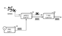
- Telecommunications carriers that provide reference time information to various users generally use an antenna to receive radio signals transmitted from satellites of the Global Navigation Satellite System (GNSS) 32, as shown in the communication system of FIG. 1, and constantly keep track of the reference time using an ePRTC (extensive Precise Time Reference Device) 31.
- GNSS Global Navigation Satellite System
- the GNSS32 signal arriving at the high-precision time reference device 31 may be temporarily interrupted.
- the high-precision time reference device 31 is no longer able to supply reference time information to the downstream high-precision time synchronization device (T-BC: Telecom Boundary Clock) 34.
- the high precision time reference device 31 performs holdover of the reference time using the highly stable clock frequency output by the high precision frequency reference device 33. In other words, by supplying the frequency output by the high precision frequency reference device 33, an increase in the time error of the reference time (local time) grasped by the high precision time reference device 31 during the period when the GNSS 32 signal is interrupted is prevented.
- the high-precision time reference device 31 Before holding over the reference time, the high-precision time reference device 31 must take a sufficient amount of time to learn the clock frequency output by the high-precision frequency reference device 33. Therefore, as shown in FIG. 2, the high-precision frequency reference device 33 must supply a clock frequency to the high-precision time reference device 31 for the entire "clock supply period" T0, from time tn, 14 days before time t0, when the GNSS 32 signal is interrupted, to time tp, 14 days after time t0, when the GNSS 32 signal is interrupted.
- the high-precision frequency reference device 33 must constantly supply a clock frequency to the high-precision time reference device 31.
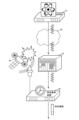
- the communication system in FIG. 3 includes an optical clock 41, a synchronization network 42, a frequency distribution system 43, a time reference device 44, and a GNSS 45.
- the highly accurate frequency signal output by the optical clock 41 is input to the time reference device 44 via the synchronization network 42 and frequency distribution system 43. Therefore, if the time information supplied from the GNSS 45 to the time reference device 44 is interrupted, the time reference device 44 can prevent the time error from increasing by using the frequency supplied from the optical clock 41.
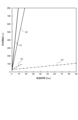
- Time errors A1 to A4 which are representative examples of four types of highly accurate clocks, are shown in Fig. 4.
- the time error A4 of the optical clock (higher accuracy than a frequency accuracy (frequency precision) of 10 -14 ) is smaller than the time error A3 of the ePRTC (when a clock combiner is used), the time error A2 of the high-precision cesium atomic clock (frequency accuracy of 5 x 10 -13 ), and the time error A1 of the standard cesium atomic clock (frequency accuracy of 10 -12 ).
- the optical clock 41 is used as in the communication system shown in Fig. 3, it is possible to implement a holdover of the time for a longer period of time than the present in the time reference device 44, and the time error can be maintained within a small range even during a period when time information from the GNSS 45 is interrupted.
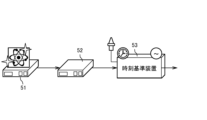
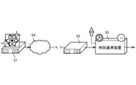
- Figures 5 and 6 show examples of communication system configurations that can be envisaged when using an optical clock.
- the output of optical clock 51 is connected to the input of frequency distribution device 52, and the output of frequency distribution device 52 is connected to the input of time reference device 53.
- the input is to the frequency distribution system via optical network 54, and the output is connected to the input of time reference device 53.
- the frequency accuracy of the optical clock supplied from the frequency distribution device is extremely high. Therefore, the time reference device 53 shown in Figures 5 and 6 can prevent time errors with the same accuracy as the optical clock 51 by maintaining the time using the frequency of the optical signal supplied from the frequency distribution device 52, even during periods when time information from the GNSS is cut off.
- optical clocks it is generally difficult for optical clocks to operate continuously for long periods of time. Furthermore, if an external disturbance such as vibration occurs, there is a possibility that the optical clock and optical network may temporarily lose synchronization. For this reason, in an environment where a highly accurate clock frequency must be continuously supplied to a time reference device for a long period of time, such as the example shown in Figure 2, it is practically difficult to use optical clocks.
- the present invention has been made in consideration of the above situation, and aims to provide a time reference system and a time synchronization control method that can reduce the time error in the reference time provided to users in a situation where high-priority time information such as GNSS is interrupted.
- a first reference frequency generating unit capable of internally generating a first frequency signal having a stable frequency and a second reference frequency generating unit capable of outputting a second frequency signal having a higher accuracy than the first frequency signal are used, Monitoring an operation state of the second reference frequency generating unit, When the second frequency signal is not present or is not stable, the first frequency signal is preferentially selected over the second frequency signal; When the second frequency signal is stably present, the second frequency signal is preferentially selected over the first frequency signal; The selected first frequency signal or the selected second frequency signal is utilized for precise time synchronization.
- the time reference system and the time synchronization control method of the present invention can reduce the time error of the reference time provided to the user in a situation where high-priority time information such as GNSS is lost.
- the first frequency signal and the second frequency signal are selected taking into consideration the priority depending on the situation, the first frequency signal and the second frequency signal do not need to be able to be supplied continuously for a long period of time. Therefore, it is possible to improve the time accuracy by using, for example, an optical clock that is difficult to operate continuously for a long period of time, and there is also a reduced possibility that periods when the frequency of the optical clock is not synchronized or sudden short-term desynchronization will have a significant impact on the time accuracy.
- FIG. 1 is a block diagram showing a typical time reference device and the main components connected thereto.
- FIG. 2 is a time chart showing the relationship between the time when the time signal from the GNSS satellite is interrupted and the clock supply period.
- FIG. 3 is a block diagram showing an example of the configuration of a communication system assumed when the time reference device uses an optical clock.
- FIG. 4 is a graph showing typical time accuracy of four types of clocks.
- FIG. 5 is a block diagram showing a first example of a configuration of a communication system in which an optical clock and a time reference device are connected.
- FIG. 6 is a block diagram showing a second configuration example of a communication system in which an optical clock and a time reference device are connected.
- FIG. 1 is a block diagram showing a typical time reference device and the main components connected thereto.
- FIG. 2 is a time chart showing the relationship between the time when the time signal from the GNSS satellite is interrupted and the clock supply period.
- FIG. 3 is a block diagram showing an example
- FIG. 7 is a time chart showing an example of the operation of the time reference system in the embodiment of the present invention.
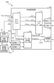
- FIG. 8 is a block diagram showing the internal configuration and peripheral components of a time reference system according to an embodiment of the present invention.
- FIG. 9 is a flowchart showing a characteristic operation example of the time reference system in the embodiment of the present invention.
- FIG. 10 is a block diagram showing a modified example of the time reference system in the embodiment of the present invention.
- the time reference device 10 in this embodiment is in an environment in which it can use an ultra-high precision frequency signal (second frequency signal) supplied from an optical clock or the like, similar to the time reference device 44 shown in FIG. 3.
- the time reference device 10 in this embodiment is also configured to simultaneously use a frequency signal (first frequency signal) that is less precise than an optical clock but can be used continuously.
- the first frequency signal can be generated using, for example, a cesium atomic clock.
- the second frequency signal supplied from an optical clock or the like is highly accurate, but it takes some time for the second frequency signal to reach a stable synchronized state after the optical clock or the like starts operating.
- the first frequency signal can be used continuously at all times.
- the time reference device 10 of this embodiment therefore preferentially selects the first frequency signal at the time tx when time information from the GNSS satellites is lost, and uses this first frequency signal for time synchronization. In addition, the time reference device 10 starts monitoring from time tx whether the second frequency signal is in a stable output state.
- the time reference device 10 detects at time t0 that the second frequency signal is being stably output, it ends the free-running period T1 shown in FIG. 7, preferentially selects the second frequency signal, and starts time synchronization to synchronize with the second frequency signal. From the time tx when time information from the GNSS satellites is lost until time t1, 14 days later (the period T1+T2), it is necessary to maintain the time error within the specification range (for example, 100 ns).
- a relatively low-precision first frequency signal is used, so the time error per unit time that occurs in the reference time output by the time reference device 10 is relatively large.
- the time error at time t0 is maintained within the standard range (e.g., 100 ns).
- time synchronization is performed using an ultra-high-precision second frequency signal obtained by an optical clock or the like. As a result, almost no time error occurs during the period from t0 to t1, and even at time t1, 14 days after time tx, the time error is maintained within the allowable error range (e.g., 100 ns).
- the time reference system 100 shown in Fig. 8 includes a time reference device 10 and an optical clock network 20.
- the time reference signal SG1 input to the time reference device 10 can be obtained, for example, by receiving radio waves from a GNSS satellite.
- the signal actually obtained from the GNSS satellite is a digital signal including latitude, longitude, time, etc., and the time reference device 10 inputs the signal SG1 as an electrical signal of the reference time based on the received digital signal.
- the optical clock network 20 shown in FIG. 8 can be constructed using, for example, the optical clock 41, synchronization network 42, and frequency distribution system 43 shown in FIG. 3.
- the frequency distribution system 43 is equipped with functions such as frequency synchronization, distribution, and photoelectric conversion. Therefore, the optical clock network 20 can supply, for example, reference frequency information having the same accuracy as that of the optical clock 41 located in a remote location away from the time reference device 10 to the time reference device 10 as the signal SG3.
- reference frequency information is transmitted over the network as an optical signal, but the signal SG3 that the optical clock network 20 supplies to the time reference device 10 is an electrical signal that matches the interface specifications on the time reference device 10 side.
- the reference frequency may be supplied in the form of an optical signal as the signal SG3.
- the main functions of the time reference device 10 shown in Figure 8 are a time recovery block 11, a local frequency clock section 12, a local time scale section 13, a frequency interface (Fre. I/F) 14, a time interface (Time I/F) 15, a phase interface 16 (Phase I/F), and a frequency interface 17.
- a time recovery block 11 The main functions of the time reference device 10 shown in Figure 8 are a time recovery block 11, a local frequency clock section 12, a local time scale section 13, a frequency interface (Fre. I/F) 14, a time interface (Time I/F) 15, a phase interface 16 (Phase I/F), and a frequency interface 17.
- the time recovery block 11 can input a reference time signal SG1 from a GNSS or the like.
- the time recovery block 11 can also transmit a special signal SG2, which will be described later, to the optical clock network 20.
- the time recovery block 11 can also supply each of the signals SG11, SG12, and SG13 to the local time scale unit 13.
- the signals SG12 and SG13 each contain time and phase information.
- the time recovery block 11 can also supply a signal SG14 to the local frequency clock unit 12.
- the signal SG14 contains frequency information obtained from a GNSS or the like.
- the local frequency clock unit 12 has a function of generating a unique local frequency clock signal internally.
- the accuracy of this local frequency clock is, for example, about 10-12 .
- the local frequency clock unit 12 supplies to the output a frequency appropriately selected from multiple types of frequencies according to a predetermined priority order and situation.
- Priorities 1 to 3 of the multiple types of frequencies are determined in advance as follows.
- Priority 1 Frequency of signal SG14 (GNSS frequency)
- Priority 2 Frequency of signal SG3 (frequency of optical clock accuracy: second frequency signal)
- Priority 3 Local frequency clock (internally generated frequency: first frequency signal)
- the local time scale unit 13 can output information about the GNSS reference time input as the signal SG12 to the time interface 15. Furthermore, in a situation where the GNSS reference time input as the signal SG12 is interrupted, the local time scale unit 13 adjusts the local time so that it is synchronized with the signal SG15 of the frequency selected by the local frequency clock unit 12, and outputs information about the local time to the time interface 15. In other words, the local time scale unit 13 performs holdover.
- Fig. 9 An example of a characteristic operation of the time base system 100 shown in Fig. 8 is shown in Fig. 9. The operation of Fig. 9 will be described below.
- the time recovery block 11 in the time reference device 10 constantly monitors the state of the signal SG1 in step S11 to check whether it is detecting a signal from the GNSS and whether it is interrupted. If the time recovery block 11 is detecting a signal from the GNSS (Yes), the process repeats step S11. Then, if it detects that the time recovery block 11 is no longer detecting a signal from the GNSS (No), the process proceeds to step S12.
- step S12 the time recovery block 11 uses the signal SG2 to instruct the optical clock network 20 to start transmitting an optical frequency signal.
- the signal SG2 is, for example, an electrical signal, and is used as a notification to the synchronization monitoring unit 201 that controls the optical clock network 20. After that, the process returns to step S11.
- step S14 the synchronization monitor 201 determines whether or not synchronization has been completed. If synchronization has not been completed (No), the process repeats step S14. Then, when the frequency synchronization is completed, the process proceeds from step S14 to the next step S15, where the optical clock network 20 starts transmitting a signal SG3 which is a highly accurate frequency signal.
- the synchronization monitoring unit 201 of the optical clock network 20 monitors in step S16 whether or not there is a loss of frequency synchronization within the optical clock network 20. For example, if an abnormality occurs in the operation of the optical clock 41, or if a loss of synchronization occurs in an optical clock or optical frequency comb within the optical clock network 20 due to an external disturbance such as vibration, the synchronization monitoring unit 201 of the optical clock network 20 detects this in step S16 and proceeds to the next step S17. In step S17, the synchronization monitoring unit 201 of the optical clock network 20 temporarily suspends the sending of the signal SG3, returns to step S13, and restarts frequency synchronization within the optical clock network 20.
- the local frequency clock unit 12 selects one of the three frequencies according to a predetermined priority order and the situation, and outputs the selected frequency as the signals SG15 and SG16 in step S18.
- Priority 1 Frequency of signal SG14 (GNSS frequency)
- Priority 2 Frequency of signal SG3 (frequency of optical clock accuracy: second frequency signal)
- Priority 3 Local frequency clock (internally generated frequency: first frequency signal)
- the local frequency clock unit 12 selects the frequency of signal SG14 in step S18 and outputs it as signal SG15.
- the local frequency clock unit 12 selects the frequency of signal SG3, which has the second highest priority, in step S18 and outputs it as signal SG15.
- the optical clock network 20 immediately after the optical clock network 20 is started up or in a situation where synchronization is lost, the optical clock network 20 does not send out signal SG3, so the local frequency clock unit 12 selects the local frequency clock, which has the third highest priority, in step S18 and outputs it as signal SG15.
- the local time scale unit 13 controls the local time to maintain (holdover) using the frequency of the signal SG15 output by the local frequency clock unit 12, and sends local time information to the time interface 15 (steps S19, S20).
- the signal SG3 is output from the optical clock network 20, and the local frequency clock unit 12 selects the signal SG3, which has the second highest priority, and outputs it as the signal SG15. Furthermore, the local time scale unit 13 generates a local time synchronized with the frequency of the highly accurate signal SG3. In other words, during the period T2 from time t0 to time t1 shown in FIG. 7, the frequency of the signal SG3, which has the same accuracy as the optical clock 41, affects the change in the time error.
- the free-running period T1 shown in FIG. 7 can be shortened, it is easy to maintain the time error at time t0 within the tolerance (100 ns) even if the accuracy of the local frequency clock is relatively low.
- it is possible to synchronize with an ultra-high accuracy frequency by using an optical clock or the like after time t0 it is also easy to maintain the time error within the tolerance (100 ns) during the period from time tx, when the GNSS signal is interrupted, to time t1.
- the frequency of the local clock is used again to perform time holdover during the period when the frequency of the optical clock is interrupted, so the optical clock can be used practically.
- the configuration of the modified time reference system 100A is shown in FIG. 10. This configuration is used when the accuracy of the local frequency clock inside the time reference device is low, for example, about 10 ⁇ 6 .
- the time reference system 100A shown in FIG. 10 includes a time reference device 10A, an optical clock network 20, and a high-precision frequency reference device 25 capable of continuous operation, such as a cesium atomic clock.
- the high-precision frequency reference device 25 functions as a third reference frequency generating unit capable of outputting a third frequency signal with a stable frequency.
- the optical clock network 20 functions as a second reference frequency generating unit capable of outputting a second frequency signal with a higher accuracy than the third frequency signal.
- the frequency accuracy of the signal SG4 output by the high-precision frequency reference device 25 in FIG. 10 is lower than the frequency accuracy of an optical clock.
- the high-precision frequency reference device 25 is capable of continuous operation for a long period of time.
- the frequency of the high-precision frequency reference device 25 is used for only a relatively short period of time, such as the free-running period T1 shown in FIG. 7, the increase in time error can be kept relatively small.
- the time reference device 10A in FIG. 10 is equipped with a frequency interface (Opt.Fre.I/F) 14A for inputting the frequency of signal SG3, and a frequency interface (Cs Fre.I/F) 18 for inputting the frequency of signal SG4.
- a frequency interface Opt.Fre.I/F
- Cs Fre.I/F frequency interface
- the local frequency clock unit 12A in the time reference device 10A can appropriately select one of the three types of signals SG14, SG3, and SG4 as a highly accurate frequency signal according to the predefined priority order and the situation.
- Priorities 1 to 3 are defined as follows: Priority 1: Frequency of signal SG14 (GNSS frequency) Priority 2: Frequency of signal SG3 (frequency of optical clock accuracy: second frequency signal) Priority 3: Frequency of signal SG4 (frequency of the high precision frequency standard device 25: third frequency signal)
- the local frequency clock unit 12A selects the frequency of signal SG14 in step S18 and outputs it as signal SG15.
- the local frequency clock unit 12A selects the frequency of signal SG3, which has the second highest priority, in step S18 and outputs it as signal SG15.
- the optical clock network 20 immediately after the optical clock network 20 is started up or in a situation where synchronization is lost, the optical clock network 20 does not send out signal SG3, so the local frequency clock unit 12A selects signal SG4, which has the third highest priority, in step S18 and outputs it as signal SG15.
- the local time scale unit 13 controls the local time to maintain (holdover) using the frequency of the signal SG15 output by the local frequency clock unit 12A, and sends local time information to the time interface 15 (steps S19, S20).
- signals SG14 and SG3 do not appear for a while from time tx when the signal from GNSS reaching the time reference device 10A is cut off until synchronization of the optical clock network 20 is established, so the local frequency clock unit 12A selects the frequency of signal SG4 and outputs it as signal SG15. Also, the local time scale unit 13 generates a local time held over by the local frequency clock. In other words, during the free-running period T1 from time tx to time t0 shown in FIG. 7, the frequency accuracy of signal SG4, i.e., the accuracy of the high-precision frequency reference device 25, affects the change in the time error.
- the signal SG3 is output from the optical clock network 20, and the local frequency clock unit 12A selects the signal SG3, which has the second highest priority, and outputs it as the signal SG15. Furthermore, the local time scale unit 13 generates a local time synchronized with the frequency of the highly accurate signal SG3. In other words, during the period T2 from time t0 to time t1 shown in FIG. 7, the frequency of the signal SG3, which has the same accuracy as the optical clock 41, affects the change in the time error.
- the free-running period T1 shown in FIG. 7 can be shortened, for example, if the frequency of the external signal SG4 has a frequency accuracy of about 10-12 of the high-precision frequency reference device 25, it is easy to maintain the time error at time t0 within the allowable value (100 ns).
- optical clock network 20 shown in Figures 8 and 10 another device capable of ensuring the same frequency accuracy may be connected. Also, in place of the high-precision frequency reference device 25 shown in Figure 10, another device capable of ensuring the same frequency accuracy may be connected.
- a first reference frequency generating unit capable of internally generating a first frequency signal (local frequency clock) having a stable frequency
- a second reference frequency generating unit capable of outputting a second frequency signal (signal SG3) having a higher accuracy than the first frequency signal
- the operating state of the second reference frequency generating unit is monitored (steps S14 and S16).
- the first frequency signal is preferentially selected over the second frequency signal (step S18); In a state where the second frequency signal is stably present, the second frequency signal is preferentially selected over the first frequency signal (step S18); Utilizing the selected first frequency signal or the selected second frequency signal for accurate time synchronization (step S19); A method for controlling time synchronization in a time reference system.
- the time synchronization control method of the time reference system described in [1] above even if the second reference frequency generating unit uses an optical clock, it is only necessary to start the operation of the optical clock at the timing (time tx) when the GNSS signal is interrupted, so there is no need to operate the optical clock continuously for a long period of time, and the system can be operated practically.
- the free-running period (T1) from when the optical clock is started until the synchronization of its frequency stabilizes, the synchronization of the local time can be maintained using the first frequency signal.
- the free-running period (T1) is relatively short, it is easy to maintain the time error that occurs during that period within the allowable value (e.g., 100 [ns]).
- the frequency of the ultra-high precision optical clock can be used, so the time error can be maintained within the allowable value (e.g., 100 [ns]) for a period of, for example, 14 days or more.
- a third reference frequency generating unit capable of outputting a third frequency signal having higher precision than the first frequency signal is further utilized; Monitor the operation state of the second reference frequency generating unit (optical clock network 20), When the second frequency signal is not present or is not stable, the third frequency signal is preferentially selected over the second frequency signal; When the second frequency signal is stably present, the second frequency signal is preferentially selected over the third frequency signal; Utilizing the selected third frequency signal or the selected second frequency signal for precise time synchronization;
- a time synchronization control method for the time base system described in [1] above According to the time synchronization control method of the time reference system described above in [2], even if a sufficiently accurate internal clock is not available, it becomes easy to maintain the time error that occurs during holdover within an allowable value.
- step S18 monitoring the state of a time reference signal (signal SG1) having a higher priority than the second frequency signal;
- time synchronization is performed based on the time reference signal (steps S18 and S19).
- the selected first frequency signal or the selected second frequency signal is used for accurate time holdover (step S19).
- the first frequency signal and the second frequency signal are appropriately used when the time reference signal is not detected, so that it is possible to reduce the time error that occurs during the period (time tx to t1) when the time reference signal obtained from the GNSS is interrupted and holdover of the reference time is performed.
- the time synchronization control method of the time reference system described in [4] above when the time reference signal is not detected, the synchronization process of the second reference frequency generation unit is started, so that even in a situation where a signal such as GNSS is cut off at an unpredictable timing (time tx), there is no need to keep an optical clock or the like running at all times.
- time tx a signal such as GNSS is cut off at an unpredictable timing
- the output of the second frequency signal is stopped, so that an increase in the time error caused by the second frequency signal can be suppressed.
- a first reference frequency generating unit capable of internally generating a first frequency signal (local frequency clock or signal SG4) having a stable frequency
- a second reference frequency generating unit capable of outputting a second frequency signal (signal SG3) having higher accuracy than the first frequency signal
- a synchronization monitor unit (synchronization monitor unit 201: steps S14 and S16) that monitors the operating state of the second reference frequency generation unit
- a signal selection unit (local frequency clock unit 12) that, when the second frequency signal is not present or is unstable, selects the first frequency signal with priority over the second frequency signal, and, when the second frequency signal is present and stable, selects the second frequency signal with priority over the first frequency signal (step S18);
- a time synchronization unit local time scale unit 13) that uses the first frequency signal or the second frequency signal selected by the signal selection unit for accurate time synchronization
- a time reference system comprising:
- the operation of the optical clock can be started at the timing (time tx) when the GNSS signal is interrupted, so there is no need to operate the optical clock continuously for a long period of time, and the system can be operated practically.
- the free-running period (T1) from when the optical clock is started until the frequency synchronization is stabilized, the first frequency signal can be used to maintain local time synchronization.
- the free-running period (T1) is relatively short, it is easy to maintain the time error that occurs during that period within the allowable value (e.g., 100 [ns]).
- the frequency of the ultra-high precision optical clock can be used, so the time error can be maintained within the allowable value (e.g., 100 [ns]) for a period of, for example, 14 days or more.
- a third reference frequency generating unit (high precision frequency reference device 25) capable of outputting a third frequency signal having a higher accuracy than the first frequency signal
- the signal selection unit (local frequency clock unit 12) preferentially selects the third frequency signal over the second frequency signal when the second frequency signal is not present or is unstable, and preferentially selects the second frequency signal over the third frequency signal when the second frequency signal is present and stable
- the time synchronization unit (local time scale unit 13) utilizes the third frequency signal or the second frequency signal selected by the signal selection unit for accurate time synchronization.
- the time reference system according to claim 5.
- the time reference system of the configuration [6] above makes it easy to maintain the time error that occurs during holdover within an acceptable range, even when a sufficiently accurate internal clock is not available.
- a time reference monitoring unit (step S11) that monitors a state of a time reference signal (signal SG1) having a higher priority than the second frequency signal;
- the time synchronization unit executes time synchronization based on the time reference signal when the time reference signal is normally present, and executes time holdover based on the first frequency signal or the second frequency signal selected by the signal selection unit when the time reference signal is not detected (steps S18 and S19).
- the time reference system according to [6] above.
- the first frequency signal and the second frequency signal are appropriately used, so that it is possible to reduce the time error that occurs during the period (time tx to t1) when the time reference signal obtained from the GNSS is interrupted and a holdover of the reference time is performed.
- the second reference frequency generating unit starts a synchronization process of the second frequency signal when the time reference signal is not detected (steps S11, S12, S13).
- the second reference frequency generating unit starts outputting the second frequency signal when it detects completion of synchronization of the second frequency signal (steps S14 and S15).
- the second reference frequency generating unit stops outputting the second frequency signal when it detects that the second frequency signal is out of sync (steps S16 and S17). While the second frequency signal is not synchronized, the first frequency signal or the third frequency signal is preferentially used for time holdover.
- the time reference system according to [7] above.
- the synchronization process of the second reference frequency generating unit is started, so there is no need to keep optical clocks running at all times, even in situations where GNSS or other signals are cut off at unpredictable times (time tx).
- the output of the second frequency signal stops, so that the increase in time error caused by the second frequency signal can be suppressed.
- Time standard device 10A Time standard device 11 Time recovery block 12, 12A Local frequency clock unit 13 Local time scale unit 14, 14A, 17 Frequency interface 15 Time interface 16 Phase interface 20
- Optical clock network 201 Synchronization monitor unit 25 High precision frequency standard device 31 High precision time standard device 32 GNSS 33 High-precision frequency standard device 34 High-precision time synchronization device 41
- Optical clock 42 Synchronization network 43
- Frequency distribution system 44 Time standard device 45 GNSS
- Optical clock 52 Frequency distribution device 53 Time reference device 54
- Optical network 100 100A Time reference system SG1, SG2, SG3, SG4 Signal SG11, SG12, SG13, SG14, SG15, SG16 Signal T1 Free-running period
Landscapes
- Engineering & Computer Science (AREA)
- Computer Networks & Wireless Communication (AREA)
- Signal Processing (AREA)
- Synchronisation In Digital Transmission Systems (AREA)
Abstract
【解決手段】GNSS等の時刻情報が途絶えた状況で、ユーザに提供される基準時刻の時刻誤差を許容値以内に減らす。周波数の安定した第1の周波数信号を出力可能な第1の基準周波数生成部と、これよりも精度の高い第2の周波数信号を出力可能な第2の基準周波数生成部とを併用する。前記第2の基準周波数生成部の動作状態を監視して状況を把握し、前記第2の周波数信号が存在しない状態、又は安定していない状態では、前記第2の周波数信号よりも前記第1の周波数信号を優先的に選択する。前記第2の周波数信号が安定して存在している状態では、前記第1の周波数信号よりも前記第2の周波数信号を優先的に選択する。選択した前記第1の周波数信号又は前記第2の周波数信号を時刻同期に利用する。第2の周波数信号は光時計等で生成し、第1の周波数信号はセシウム原子時計等で生成し、時刻誤差を例えば100[ns]以内に維持する。
Description
本発明は、時刻基準システムおよびその時刻同期制御方法に関する。
通信事業者は、様々な場所に存在している多数のユーザのそれぞれの端末に対して正確な時刻の情報を通信サービスとして提供する必要がある。したがって、通信事業者は正確な時刻の情報を各ユーザに配信するために必要な通信設備として、時刻同期網および周波数同期網を有している。
例えば、時刻同期網に必要な高精度時刻基準装置(ePRTC:enhanced primary reference time clocks)の標準規格(ITU-T G.8272.1)が非特許文献1に示されている。
"Timing characteristics of enhanced primary reference time clocks", Recommendation ITU-T G.8272.1/Y.1367.1, ITU-T.
非特許文献1に示されているITU-Tの規定(ePRTC(G.8272.1))では、基準時刻の時刻誤差を14日間で100[ns]以内に維持することが求められている。
基準時刻の情報を様々なユーザに提供する通信事業者は、一般的には図1に示す通信システムのように、GNSS(Global Navigation Satellite System)32の衛星から送信される電波の信号をアンテナで受信して高精度時刻基準装置(ePRTC)31で基準時刻を常時把握している。
基準時刻の情報を様々なユーザに提供する通信事業者は、一般的には図1に示す通信システムのように、GNSS(Global Navigation Satellite System)32の衛星から送信される電波の信号をアンテナで受信して高精度時刻基準装置(ePRTC)31で基準時刻を常時把握している。
しかし、様々な要因により高精度時刻基準装置31に到来するGNSS32の信号が一時的に途絶える場合がある。そして、GNSS32の信号が途絶えると高精度時刻基準装置31は基準時刻の情報を下流側の高精度時刻同期装置(T-BC:テレコム・バウンダリ・クロック)34に供給できなくなる。
そこで、GNSS32の信号が途絶えた場合には、高精度時刻基準装置31は高精度周波数基準装置33が出力する安定度の高いクロック周波数を利用して基準時刻のホールドオーバを実施する。つまり、高精度周波数基準装置33が出力する周波数を供給することで、GNSS32の信号が途絶えている期間において高精度時刻基準装置31が把握している基準時刻(ローカル時刻)の時刻誤差の増大を防止する。
また、基準時刻のホールドオーバを実施する前に、高精度時刻基準装置31は十分な時間をかけて高精度周波数基準装置33が出力するクロック周波数の学習を行う必要がある。そのため、図2に示すようにGNSS32の信号が途絶える時刻t0の14日前の時刻tnから、GNSS32の信号が途絶えた時刻t0の14日後の時刻tpまでの「クロック供給期間」T0の全区間で、高精度周波数基準装置33から高精度時刻基準装置31に対してクロック周波数を供給する必要がある。
しかし、GNSS32の信号が途絶える時刻t0は予期できない。したがって、実際には高精度周波数基準装置33から高精度時刻基準装置31に対してクロック周波数を常時供給しなければならない。
一方、今後はより厳しい時刻維持要件になることが見込まれている。そのため、通信事業者は現状の高精度周波数基準装置33よりも更に精度の高いクロック周波数を高精度時刻基準装置31に常時供給できるように考慮する必要がある。
そこで、通信事業者が基準時刻の情報をユーザに配信する際に、例えば図3に示した構成の通信システムを利用することが想定される。図3の通信システムは、光時計41、同期ネットワーク42、周波数配信システム43、時刻基準装置44、及びGNSS45を含んでいる。
図3に示した通信システムにおいて、光時計41が出力する精度の高い周波数信号は、同期ネットワーク42、周波数配信システム43を経由して時刻基準装置44に入力される。したがって、GNSS45から時刻基準装置44に供給される時刻情報が途絶えた場合には、時刻基準装置44は光時計41から供給される周波数を利用して時刻誤差の増大を防ぐことが可能である。
精度の高い4種類の時計の代表例となる時刻誤差A1~A4を図4に示す。図4に示すように、光時計の時刻誤差(周波数確度(周波数の正確度)10-14よりも高精度)A4は、ePRTC(クロックコンバイナーを利用した場合)の時刻誤差A3、高精度セシウム原子時計の時刻誤差(周波数確度5×10-13)A2、標準セシウム原子時計の時刻誤差(周波数確度10-12)A1と比べて時刻誤差が小さい。つまり、図3に示した通信システムのように光時計41を利用すれば、現在よりも長期間の時刻のホールドオーバを時刻基準装置44において実施することが可能であり、GNSS45からの時刻情報が途絶えている期間においても時刻誤差を小さい範囲内に維持可能である。
光時計を利用する場合に想定される通信システムの構成例を図5、図6にそれぞれ示す。図5に示した通信システムにおいては、光時計51の出力を周波数配信装置52の入力に接続し、周波数配信装置52の出力を時刻基準装置53の入力に接続してある。また、図6に示した通信システムにおいては、光ネットワーク54を経由して周波数配信システムに入力し、出力を時刻基準装置53の入力と接続してある。
図5、図6の構成において、周波数分配装置から供給される光時計の周波数精度は、極めて高精度である。したがって、図5、図6に示した時刻基準装置53は、GNSSからの時刻情報が途絶えている期間においても、周波数配信装置52から供給される光信号の周波数を利用して時刻の維持を行うことで、光時計51と同等の精度で時刻誤差の発生を防止できる。
しかしながら、一般的に光時計は長時間の連続運転が困難である。更に、例えば振動などの外乱が発生した場合に、一時的に光時計および光ネットワークにおける同期が外れる可能性もある。そのため、図2に示した例のように長時間に亘って連続的に高精度のクロック周波数を時刻基準装置に供給しなければならない環境においては、現実的には光時計の利用は困難である。
本発明は、上記の状況に鑑みてなされたものであり、GNSS等の優先順位の高い時刻情報が途絶えた状況において、ユーザに提供される基準時刻の時刻誤差を減らすことが可能な時刻基準システムおよびその時刻同期制御方法を提供することを目的とする。
本発明の時刻基準システムの時刻同期制御方法では、
周波数の安定した第1の周波数信号を内部で生成可能な第1の基準周波数生成部と、前記第1の周波数信号よりも精度の高い第2の周波数信号を出力可能な第2の基準周波数生成部とを利用し、
前記第2の基準周波数生成部の動作状態を監視して、
前記第2の周波数信号が存在しない状態、又は安定していない状態では、前記第2の周波数信号よりも前記第1の周波数信号を優先的に選択し、
前記第2の周波数信号が安定して存在している状態では、前記第1の周波数信号よりも前記第2の周波数信号を優先的に選択し、
選択した前記第1の周波数信号または前記第2の周波数信号を正確な時刻同期に利用する。
周波数の安定した第1の周波数信号を内部で生成可能な第1の基準周波数生成部と、前記第1の周波数信号よりも精度の高い第2の周波数信号を出力可能な第2の基準周波数生成部とを利用し、
前記第2の基準周波数生成部の動作状態を監視して、
前記第2の周波数信号が存在しない状態、又は安定していない状態では、前記第2の周波数信号よりも前記第1の周波数信号を優先的に選択し、
前記第2の周波数信号が安定して存在している状態では、前記第1の周波数信号よりも前記第2の周波数信号を優先的に選択し、
選択した前記第1の周波数信号または前記第2の周波数信号を正確な時刻同期に利用する。
本発明の時刻基準システムおよびその時刻同期制御方法によれば、GNSS等の優先順位の高い時刻情報が途絶えた状況において、ユーザに提供される基準時刻の時刻誤差を減らすことができる。すなわち、前記第1の周波数信号および前記第2の周波数信号を状況に応じて優先順位を考慮して選択するので、前記第1の周波数信および前記第2の周波数信号は長時間連続的に供給可能である必要はない。そのため、例えば長時間の連続運転が困難な光時計を利用して時刻精度を上げることが可能であり、光時計の周波数が同期していない期間や、突発的に発生する短期間の同期外れが時刻精度に大きな影響を及ぼす可能性も低くなる。
本発明の実施形態について各図を参照しながら以下に説明する。
<時刻同期制御方法の概要>
本発明の実施形態における時刻基準装置10の動作例を図7に示す。また、この時刻基準装置10を含む時刻基準システム100の構成例を図8に示す。
<時刻同期制御方法の概要>
本発明の実施形態における時刻基準装置10の動作例を図7に示す。また、この時刻基準装置10を含む時刻基準システム100の構成例を図8に示す。
本実施形態における時刻基準装置10は、例えば図3中に示した時刻基準装置44と同様に、光時計などから供給される超高精度の周波数信号(第2の周波数信号)を利用できる環境にある。また、本実施形態の時刻基準装置10は、光時計よりも精度が低いが連続的に利用できる周波数信号(第1の周波数信号)も同時に利用できるように構成される。第1の周波数信号は、例えばセシウム原子時計を用いて生成できる。
図7に示した例では、時刻基準装置10が存在する場所において、時刻txでGNSSの衛星からの時刻情報が途絶え、且つ時刻t0で第2の周波数信号が安定して出力される状態になった状況を想定している。
光時計等から供給される第2の周波数信号は非常に精度が高いが、光時計等が動作を開始してから第2の周波数信号が安定した同期状態になるまでにはある程度の時間が必要になる。一方、第1の周波数信号は常時連続的に利用できる。
そこで、本実施形態の時刻基準装置10は、GNSSの衛星からの時刻情報が途絶えた時刻txで第1の周波数信号を優先的に選択し、この第1の周波数信号を時刻同期に利用する。また、時刻基準装置10は第2の周波数信号が安定して出力される状態かどうかの監視を時刻txから開始する。
そして、時刻基準装置10は、時刻t0で第2の周波数信号が安定して出力される状態になったことを検知すると、図7中に示した自走期間T1を終了し、第2の周波数信号を優先的に選択し、第2の周波数信号に同期するように時刻同期を開始する。GNSSの衛星からの時刻情報が途絶えた時刻txから、14日経過後の時刻t1まで(T1+T2の期間)は、時刻誤差を規格の範囲内(例えば100[ns])に維持する必要がある。
図7に示すように、自走期間T1の間は比較的精度の低い第1の周波数信号を利用するので時刻基準装置10の出力する基準時刻に生じる単位時間あたりの時刻誤差は比較的大きい。しかし、時刻txから長い時間が経過する前に自走期間T1が終了するので、時刻t0における時刻誤差は規格の範囲内(例えば100[ns])に維持される。また、時刻t0からt1までの期間(T2)の間は、光時計等により得られる超高精度の第2の周波数信号を利用して時刻同期を行う。結果としてt0からt1までの期間では、時刻誤差がほとんど発生せず、時刻txから14日経過した後の時刻t1においても時刻誤差は、許容誤差(例えば100[ns])の範囲内に維持される。
<時刻基準システムの構成例>
図8に示した時刻基準システム100は、時刻基準装置10及び光時計ネットワーク20を備えている。時刻基準装置10に入力される基準時刻(Time reference)の信号SG1は、例えばGNSSの衛星からの電波を受信することで得ることができる。GNSSの衛星から実際に得られる信号は緯度、経度、時刻等を含むデジタル信号であり、時刻基準装置10は受信したデジタル信号に基づき基準時刻の電気信号として信号SG1を入力する。
図8に示した時刻基準システム100は、時刻基準装置10及び光時計ネットワーク20を備えている。時刻基準装置10に入力される基準時刻(Time reference)の信号SG1は、例えばGNSSの衛星からの電波を受信することで得ることができる。GNSSの衛星から実際に得られる信号は緯度、経度、時刻等を含むデジタル信号であり、時刻基準装置10は受信したデジタル信号に基づき基準時刻の電気信号として信号SG1を入力する。
図8中に示した光時計ネットワーク20は、例えば図3中に示した光時計41、同期ネットワーク42、周波数配信システム43などを用いて構成できる。周波数配信システム43は周波数の同期・分配・光電変換などの機能を搭載している。したがって、光時計ネットワーク20は例えば時刻基準装置10から離れた遠隔地に配置された光時計41と同等の精度を有する基準周波数の情報を信号SG3として時刻基準装置10に供給可能である。
なお、光時計ネットワーク20の内部では、基準周波数の情報を光信号としてネットワーク上で伝送するが、光時計ネットワーク20が時刻基準装置10に供給する信号SG3については、時刻基準装置10側のインタフェースの仕様に合わせて電気信号を供給する。勿論、時刻基準装置10側が光信号の入力に対応している場合は、信号SG3として光信号の形態で基準周波数を供給しても良い。
図8に示した時刻基準装置10の内部には、主要な機能として、タイムリカバリブロック11、ローカル周波数クロック部12、ローカルタイムスケール部13、周波数インタフェース(Fre.I/F)14、時刻インタフェース(Time I/F)15、位相インタフェース16(Phase I/F)、及び周波数インタフェース17が備わっている。
タイムリカバリブロック11は、GNSS等から基準時刻の信号SG1を入力できる。また、タイムリカバリブロック11は後述する特別な信号SG2を光時計ネットワーク20に対して送信できる。また、タイムリカバリブロック11は各信号SG11、SG12、SG13をローカルタイムスケール部13に供給できる。信号SG12及びSG13は、それぞれ時刻及び位相の情報を含んでいる。また、タイムリカバリブロック11は信号SG14をローカル周波数クロック部12に供給できる。信号SG14は、GNSS等により得られる周波数(Frequency)の情報を含んでいる。
ローカル周波数クロック部12は、独自のローカル周波数クロック信号を内部で生成する機能を有する。このローカル周波数クロックの精度は、例えば、10-12程度とする。この時、例えば、1000[s]の自走期間では、10-12×1000[s]=10-9[s]=1[ns]なので、2週間で100[ns]の時刻誤差に抑える規格に対して、1000[s]程度の自走期間には十分な周波数精度である。また、ローカル周波数クロック部12は事前に決定した優先順位と状況に応じて複数種類の周波数の中から適切に選択した周波数を出力に供給する。複数種類の周波数の優先順位1~3は次のように事前に定めておく。
優先順位1:信号SG14の周波数(GNSSの周波数)
優先順位2:信号SG3の周波数(光時計精度の周波数:第2の周波数信号)
優先順位3:ローカル周波数クロック(内部で生成した周波数:第1の周波数信号)
優先順位1:信号SG14の周波数(GNSSの周波数)
優先順位2:信号SG3の周波数(光時計精度の周波数:第2の周波数信号)
優先順位3:ローカル周波数クロック(内部で生成した周波数:第1の周波数信号)
ローカルタイムスケール部13は、信号SG12として入力されるGNSSの基準時刻の情報を、時刻インタフェース15に出力できる。また、信号SG12として入力されるGNSSの基準時刻が途絶えている状況においては、ローカルタイムスケール部13は、ローカル周波数クロック部12が選択した周波数の信号SG15に同期するようにローカル時刻を調整し、ローカル時刻の情報を時刻インタフェース15に出力する。すなわち、ローカルタイムスケール部13がホールドオーバを実施する。
<時刻基準システムの動作>
図8に示した時刻基準システム100の特徴的な動作例を図9に示す。図9の動作について以下に説明する。
図8に示した時刻基準システム100の特徴的な動作例を図9に示す。図9の動作について以下に説明する。
時刻基準装置10内のタイムリカバリブロック11は、信号SG1の状態をステップS11で常時監視して、GNSSからの信号を検出しており、途切れていないかどうかを確認する。タイムリカバリブロック11がGNSSからの信号を検出しているならば(Yes)、処理はステップS11を繰り返す。そして、タイムリカバリブロック11がGNSSからの信号を検出しなくなったことを検知すると(No)、処理はステップS12に進む。
タイムリカバリブロック11は、ステップS12で信号SG2を用いて光時計ネットワーク20へ光周波数信号の送信開始を指示する。なお、信号SG2は例えば電気信号であり、光時計ネットワーク20を制御する同期監視部201への通知として利用される。その後、処理はステップS11に戻る。
光時計ネットワーク20の同期監視部201は、タイムリカバリブロック11がステップS12で送信する指示を信号SG2により検知すると、ステップS13で光時計41の動作を起動すると共に周波数の同期処理を開始する。ステップS14にて、同期監視部201は、同期が完了したか否かを判定する。同期が完了していなければ(No)、処理はステップS14を繰り返す。
そして、周波数の同期が完了すると、処理はステップS14から次のステップS15に進み、光時計ネットワーク20が高精度の周波数信号である信号SG3の送出を開始する。
そして、周波数の同期が完了すると、処理はステップS14から次のステップS15に進み、光時計ネットワーク20が高精度の周波数信号である信号SG3の送出を開始する。
光時計ネットワーク20の同期監視部201は、信号SG3の送出を開始した後、光時計ネットワーク20内部における周波数の同期外れの有無をステップS16で監視する。例えば光時計41の動作に異常が発生したり、振動などの外乱の影響で光時計ネットワーク20内の光時計や光周波数コムなどにおいて同期外れなどが生じたりすると、光時計ネットワーク20の同期監視部201がそれをステップS16で検知して次のステップS17に進む。光時計ネットワーク20の同期監視部201は、ステップS17で信号SG3の送出を一時停止してステップS13に戻り、光時計ネットワーク20の内部における周波数の同期をやり直す。
ローカル周波数クロック部12は、事前に決定した優先順位と状況に応じて、3種類の周波数の中から選択した1つの周波数を信号SG15、SG16としてステップS18で出力する。
優先順位1:信号SG14の周波数(GNSSの周波数)
優先順位2:信号SG3の周波数(光時計精度の周波数:第2の周波数信号)
優先順位3:ローカル周波数クロック(内部で生成した周波数:第1の周波数信号)
優先順位1:信号SG14の周波数(GNSSの周波数)
優先順位2:信号SG3の周波数(光時計精度の周波数:第2の周波数信号)
優先順位3:ローカル周波数クロック(内部で生成した周波数:第1の周波数信号)
すなわち、時刻基準装置10がGNSSからの信号を受信できる状況では、信号SG14の優先順位が最も高いので、ローカル周波数クロック部12は信号SG14の周波数をステップS18で選択して信号SG15として出力する。
また、時刻基準装置10に届くGNSSからの信号が途絶えた場合には、ローカル周波数クロック部12は優先順位が2番目の信号SG3の周波数をステップS18で選択して信号SG15として出力する。但し、例えば光時計ネットワーク20が起動した直後や、同期が外れているような状況では、光時計ネットワーク20が信号SG3を送出しないので、ローカル周波数クロック部12は優先順位が3番目のローカル周波数クロックをステップS18で選択して信号SG15として出力する。
ローカルタイムスケール部13は、GNSSからの信号が途絶えている状況では、ローカル時刻がローカル周波数クロック部12の出力する信号SG15の周波数を用いて時刻を維持(ホールドオーバ)するように制御し、ローカル時刻の情報を時刻インタフェース15に送出する(ステップS19、S20)。
したがって、時刻基準システム100が図9に示した制御を実施する場合には、時刻基準装置10に届くGNSSからの信号が途絶えた時刻txから光時計ネットワーク20の同期が確立するまでのしばらくの間は、信号SG14、SG3が現れないので、ローカル周波数クロック部12がローカル周波数クロックを選択する。また、ローカルタイムスケール部13がローカル周波数クロックによってホールドオーバされたローカル時刻を生成する。つまり、図7中に示した時刻txから時刻t0までの自走期間T1の間は、ローカル周波数クロックの精度が時刻誤差の変化に影響する。
また、光時計ネットワーク20の同期が確立すると、光時計ネットワーク20から信号SG3が出力されるので、ローカル周波数クロック部12は優先順位が2番目の信号SG3を選択して信号SG15として出力する。また、ローカルタイムスケール部13が精度の高い信号SG3の周波数に同期したローカル時刻を生成する。つまり、図7中に示した時刻t0から時刻t1までの期間T2の間は、光時計41と同じ精度の信号SG3の周波数が時刻誤差の変化に影響する。
図7中に示した自走期間T1を短くすることができるので、ローカル周波数クロックの精度が比較的低い場合でも時刻t0における時刻誤差を許容値(100[ns])以内に維持することは容易である。また、時刻t0以降は光時計などを利用することで超高精度の周波数に同期できるので、GNSSの信号が途絶えた時刻txから時刻t1までの期間の時刻誤差を許容値(100[ns])以内に維持することも容易である。また、一般的に光時計は長時間の連続動作が困難であるが、図7、図9の制御を行う場合には、光時計の周波数が途切れた期間は再びローカルクロックの周波数を利用して時刻のホールドオーバを行うので実用的に光時計を利用できる。
<時刻基準システムの変形例>
変形例の時刻基準システム100Aの構成を図10に示す。この構成は、時刻基準装置内部のローカル周波数クロックの精度が低い場合、例えば、10-6程度のようなときに使用する。この時、例えば、1000[s]の自走期間では、10-6×1000[s]=10-3[s]=1[ms]なので、2週間で100[ns]の時刻誤差に抑える規格に対して、1000[s]もたずに、基準値を超える時刻誤差が生じてしまう。そこで図10に示した時刻基準システム100Aは、時刻基準装置10A、光時計ネットワーク20、及び連続運転可能な高精度周波数基準装置25、例えばセシウム原子時計を備えている。高精度周波数基準装置25は、周波数の安定した第3の周波数信号を出力可能な第3の基準周波数生成部として機能する。光時計ネットワーク20は、第3の周波数信号よりも精度の高い第2の周波数信号を出力可能な第2の基準周波数生成部として機能する。
変形例の時刻基準システム100Aの構成を図10に示す。この構成は、時刻基準装置内部のローカル周波数クロックの精度が低い場合、例えば、10-6程度のようなときに使用する。この時、例えば、1000[s]の自走期間では、10-6×1000[s]=10-3[s]=1[ms]なので、2週間で100[ns]の時刻誤差に抑える規格に対して、1000[s]もたずに、基準値を超える時刻誤差が生じてしまう。そこで図10に示した時刻基準システム100Aは、時刻基準装置10A、光時計ネットワーク20、及び連続運転可能な高精度周波数基準装置25、例えばセシウム原子時計を備えている。高精度周波数基準装置25は、周波数の安定した第3の周波数信号を出力可能な第3の基準周波数生成部として機能する。光時計ネットワーク20は、第3の周波数信号よりも精度の高い第2の周波数信号を出力可能な第2の基準周波数生成部として機能する。
図4に示した例から分かるように、図10中の高精度周波数基準装置25が出力する信号SG4の周波数精度は、光時計の周波数精度よりも低い。しかし、高精度周波数基準装置25は長時間の連続動作が可能である。また、図7中に示した自走期間T1のように比較的短い期間だけ高精度周波数基準装置25の周波数を使用する場合には、時刻誤差の増加は比較的小さく維持できる。
図10中の時刻基準装置10Aは、信号SG3の周波数を入力するための周波数インタフェース(Opt.Fre.I/F)14Aと、信号SG4の周波数を入力するための周波数インタフェース(Cs Fre.I/F)18とを備えている。
時刻基準装置10A内部のローカル周波数クロック部12Aは、高精度の周波数の信号として、信号SG14、SG3、及びSG4の3種類のいずれか1つを事前に定めた優先順位と状況とに応じて適切に選択することができる。優先順位1~3は次のように定めてある。
優先順位1:信号SG14の周波数(GNSSの周波数)
優先順位2:信号SG3の周波数(光時計精度の周波数:第2の周波数信号)
優先順位3:信号SG4の周波数(高精度周波数基準装置25の精度の周波数:第3の周波数信号)
優先順位1:信号SG14の周波数(GNSSの周波数)
優先順位2:信号SG3の周波数(光時計精度の周波数:第2の周波数信号)
優先順位3:信号SG4の周波数(高精度周波数基準装置25の精度の周波数:第3の周波数信号)
すなわち、時刻基準装置10AがGNSSからの信号を受信できる状況では、信号SG14の優先順位が最も高いので、ローカル周波数クロック部12Aは信号SG14の周波数をステップS18で選択して信号SG15として出力する。
また、時刻基準装置10Aに届くGNSSからの信号が途絶えた場合には、ローカル周波数クロック部12Aは優先順位が2番目の信号SG3の周波数をステップS18で選択して信号SG15として出力する。但し、例えば光時計ネットワーク20が起動した直後や、同期が外れているような状況では、光時計ネットワーク20が信号SG3を送出しないので、ローカル周波数クロック部12Aは優先順位が3番目の信号SG4をステップS18で選択して信号SG15として出力する。
ローカルタイムスケール部13は、GNSSからの信号が途絶えている状況では、ローカル時刻がローカル周波数クロック部12Aの出力する信号SG15の周波数を用いて時刻を維持(ホールドオーバ)するように制御し、ローカル時刻の情報を時刻インタフェース15に送出する(ステップS19、S20)。
したがって、時刻基準システム100Aが図9に示した制御を実施する場合には、時刻基準装置10Aに届くGNSSからの信号が途絶えた時刻txから光時計ネットワーク20の同期が確立するまでのしばらくの間は、信号SG14、SG3が現れないので、ローカル周波数クロック部12Aが信号SG4の周波数を選択して信号SG15として出力する。また、ローカルタイムスケール部13がローカル周波数クロックによってホールドオーバされたローカル時刻を生成する。つまり、図7中に示した時刻txから時刻t0までの自走期間T1の間は、信号SG4の周波数精度、すなわち高精度周波数基準装置25の精度が時刻誤差の変化に影響する。
また、光時計ネットワーク20の同期が確立すると、光時計ネットワーク20から信号SG3が出力されるので、ローカル周波数クロック部12Aは優先順位が2番目の信号SG3を選択して信号SG15として出力する。また、ローカルタイムスケール部13が精度の高い信号SG3の周波数に同期したローカル時刻を生成する。つまり、図7中に示した時刻t0から時刻t1までの期間T2の間は、光時計41と同じ精度の信号SG3の周波数が時刻誤差の変化に影響する。
図7中に示した自走期間T1を短くすることができるので、例えば外部からの信号SG4の周波数が高精度周波数基準装置25の周波数精度10-12程度であれば、時刻t0における時刻誤差を許容値(100[ns])以内に維持することは容易である。
また、時刻t0以降は光時計などを利用することで超高精度の周波数に同期できるので、GNSSの信号が途絶えた時刻txから時刻t1までの期間の時刻誤差を許容値(100[ns])以内に維持することも容易である。また、一般的に光時計は長時間の連続動作が困難であるが、図7、図9の制御を行う場合には、GNSSの信号が途絶えた時刻txから時刻t1までの比較的短い期間だけ光時計を稼働できればよく、光時計の周波数が途切れた期間は再び高精度周波数基準装置25の周波数を利用して時刻のホールドオーバを行うので、実用的に光時計を利用できる。
<上記以外の変形の可能性>
図8、図10に示した構成では、信号SG1としてGNSSからの基準時刻の信号を時刻基準装置10に入力する場合を想定しているが、GNSS以外の信号に置き換えることも可能である。
図8、図10に示した構成では、信号SG1としてGNSSからの基準時刻の信号を時刻基準装置10に入力する場合を想定しているが、GNSS以外の信号に置き換えることも可能である。
図8に示したローカル周波数クロック部12に内蔵されるローカル周波数クロックについては、時刻基準システム100が必要とする基準時刻の許容誤差と制御のタイミングとに応じて適切な周波数精度を有する装置を適宜利用することが想定される。
図8、図10に示した光時計ネットワーク20の代わりに、それと同等の周波数精度を確保可能な別の設備を接続しても良い。また、図10に示した高精度周波数基準装置25の代わりに、それと同等の周波数精度を確保可能な別の設備を接続しても良い。
<時刻基準装置およびその時刻同期制御方法の特徴>
本発明の時刻基準装置およびその時刻同期制御方法に関する特徴的な事項について、以下の[1]~[8]に列挙する。
[1]周波数の安定した第1の周波数信号(ローカル周波数クロック)を内部で生成可能な第1の基準周波数生成部と、前記第1の周波数信号よりも精度の高い第2の周波数信号(信号SG3)を出力可能な第2の基準周波数生成部(光時計ネットワーク20)とを利用し、
前記第2の基準周波数生成部の動作状態を監視して(ステップS14、S16)、
前記第2の周波数信号が存在しない状態、又は安定していない状態では、前記第2の周波数信号よりも前記第1の周波数信号を優先的に選択し(ステップS18)、
前記第2の周波数信号が安定して存在している状態では、前記第1の周波数信号よりも前記第2の周波数信号を優先的に選択し(ステップS18)、
選択した前記第1の周波数信号または前記第2の周波数信号を正確な時刻同期に利用する(ステップS19)、
時刻基準システムの時刻同期制御方法。
本発明の時刻基準装置およびその時刻同期制御方法に関する特徴的な事項について、以下の[1]~[8]に列挙する。
[1]周波数の安定した第1の周波数信号(ローカル周波数クロック)を内部で生成可能な第1の基準周波数生成部と、前記第1の周波数信号よりも精度の高い第2の周波数信号(信号SG3)を出力可能な第2の基準周波数生成部(光時計ネットワーク20)とを利用し、
前記第2の基準周波数生成部の動作状態を監視して(ステップS14、S16)、
前記第2の周波数信号が存在しない状態、又は安定していない状態では、前記第2の周波数信号よりも前記第1の周波数信号を優先的に選択し(ステップS18)、
前記第2の周波数信号が安定して存在している状態では、前記第1の周波数信号よりも前記第2の周波数信号を優先的に選択し(ステップS18)、
選択した前記第1の周波数信号または前記第2の周波数信号を正確な時刻同期に利用する(ステップS19)、
時刻基準システムの時刻同期制御方法。
上記[1]の時刻基準システムの時刻同期制御方法によれば、例えば前記第2の基準周波数生成部が光時計を利用する場合でも、GNSS信号が途絶えたタイミング(時刻tx)で光時計の動作を起動すれば良いので、長期間に亘って連続的に光時計を稼働させる必要がなく、実用的にシステムを運用できる。また、光時計を起動してからその周波数の同期が安定するまでの自走期間(T1)の間は、前記第1の周波数信号を利用してローカル時刻の同期を維持できる。また、自走期間(T1)は比較的短いので、その間に発生する時刻誤差を許容値(例えば100[ns])以内に維持することは容易である。また、自走期間(T1)が終了した後の期間(T2)では、超高精度の光時計の周波数を利用できるので、例えば14日以上の期間に亘って時刻誤差を許容値(例えば100[ns])以内に維持できる。
[2]前記第1の周波数信号よりも精度の高い第3の周波数信号を出力可能な第3の基準周波数生成部(高精度周波数基準装置25)を更に利用し、
前記第2の基準周波数生成部(光時計ネットワーク20)の動作状態を監視して、
前記第2の周波数信号が存在しない状態、又は安定していない状態では、前記第2の周波数信号よりも前記第3の周波数信号を優先的に選択し、
前記第2の周波数信号が安定して存在している状態では、前記第3の周波数信号よりも前記第2の周波数信号を優先的に選択し、
選択した前記第3の周波数信号または前記第2の周波数信号を正確な時刻同期に利用する、
前記第2の基準周波数生成部(光時計ネットワーク20)の動作状態を監視して、
前記第2の周波数信号が存在しない状態、又は安定していない状態では、前記第2の周波数信号よりも前記第3の周波数信号を優先的に選択し、
前記第2の周波数信号が安定して存在している状態では、前記第3の周波数信号よりも前記第2の周波数信号を優先的に選択し、
選択した前記第3の周波数信号または前記第2の周波数信号を正確な時刻同期に利用する、
上記[1]に記載の時刻基準システムの時刻同期制御方法。
上記[2]の時刻基準システムの時刻同期制御方法によれば、十分に精度の高い内部クロックを利用できない場合であっても、ホールドオーバの間に生じる時刻誤差を許容値以内に維持することが容易になる。
上記[2]の時刻基準システムの時刻同期制御方法によれば、十分に精度の高い内部クロックを利用できない場合であっても、ホールドオーバの間に生じる時刻誤差を許容値以内に維持することが容易になる。
[3]前記第2の周波数信号よりも優先順位の高い時刻基準信号(信号SG1)の状態を監視し、
前記時刻基準信号が正常に現れている状態では、前記時刻基準信号に基づいて時刻同期を実行し(ステップS18、S19)、
前記時刻基準信号が検出されない時は、選択した前記第1の周波数信号または前記第2の周波数信号を正確な時刻のホールドオーバに利用する(ステップS19)、
上記[2]に記載の時刻基準システムの時刻同期制御方法。
前記時刻基準信号が正常に現れている状態では、前記時刻基準信号に基づいて時刻同期を実行し(ステップS18、S19)、
前記時刻基準信号が検出されない時は、選択した前記第1の周波数信号または前記第2の周波数信号を正確な時刻のホールドオーバに利用する(ステップS19)、
上記[2]に記載の時刻基準システムの時刻同期制御方法。
上記[3]の時刻基準システムの時刻同期制御方法によれば、前記時刻基準信号が検出されない時に前記第1の周波数信号と前記第2の周波数信号とを適切に使い分けるので、例えばGNSSから得られる時刻基準信号が途絶えて基準時刻のホールドオーバを実施する期間(時刻tx~t1)中に、発生する時刻誤差を減らすことができる。
[4]前記時刻基準信号が非検出になった時に、前記第2の基準周波数生成部の同期処理を開始し(ステップS11、S12)、
前記第2の基準周波数生成部の同期完了を検知した時に前記第2の周波数信号の出力を開始し(ステップS14、S15)、
前記第2の基準周波数生成部の同期外れを検知した時に前記第2の周波数信号の出力を停止し(ステップS16、S17)、
前記第2の周波数信号が同期していない間は、前記第1の周波数信号又は前記第3の周波数信号を優先的に時刻のホールドオーバに利用する、
上記[3]に記載の時刻基準システムの時刻同期制御方法。
前記第2の基準周波数生成部の同期完了を検知した時に前記第2の周波数信号の出力を開始し(ステップS14、S15)、
前記第2の基準周波数生成部の同期外れを検知した時に前記第2の周波数信号の出力を停止し(ステップS16、S17)、
前記第2の周波数信号が同期していない間は、前記第1の周波数信号又は前記第3の周波数信号を優先的に時刻のホールドオーバに利用する、
上記[3]に記載の時刻基準システムの時刻同期制御方法。
上記[4]の時刻基準システムの時刻同期制御方法によれば、前記時刻基準信号が非検出になった時に、前記第2の基準周波数生成部の同期処理を開始するので、予期できないタイミング(時刻tx)でGNSS等の信号が途絶える状況でも、光時計などを常時稼働させておく必要がない。また、前記第2の周波数信号の同期が確立していない状況や、同期が外れた状況では前記第2の周波数信号の出力が停止するので、前記第2の周波数信号に起因する時刻誤差の増大を抑制できる。
[5]周波数の安定した第1の周波数信号(ローカル周波数クロック又は信号SG4)を内部で生成可能な第1の基準周波数生成部(ローカル周波数クロック部12)と、
前記第1の周波数信号よりも精度の高い第2の周波数信号(信号SG3)を出力可能な第2の基準周波数生成部(光時計ネットワーク20)と、
前記第2の基準周波数生成部の動作状態を監視する同期監視部(同期監視部201:ステップS14、S16)と、
前記第2の周波数信号が存在しない状態、又は安定していない状態では、前記第2の周波数信号よりも前記第1の周波数信号を優先的に選択し、前記第2の周波数信号が安定して存在している状態では、前記第1の周波数信号よりも前記第2の周波数信号を優先的に選択する(ステップS18)信号選択部(ローカル周波数クロック部12)と、
前記信号選択部が選択した前記第1の周波数信号または前記第2の周波数信号を正確な時刻同期に利用する時刻同期部(ローカルタイムスケール部13)と、
を備える時刻基準システム。
前記第1の周波数信号よりも精度の高い第2の周波数信号(信号SG3)を出力可能な第2の基準周波数生成部(光時計ネットワーク20)と、
前記第2の基準周波数生成部の動作状態を監視する同期監視部(同期監視部201:ステップS14、S16)と、
前記第2の周波数信号が存在しない状態、又は安定していない状態では、前記第2の周波数信号よりも前記第1の周波数信号を優先的に選択し、前記第2の周波数信号が安定して存在している状態では、前記第1の周波数信号よりも前記第2の周波数信号を優先的に選択する(ステップS18)信号選択部(ローカル周波数クロック部12)と、
前記信号選択部が選択した前記第1の周波数信号または前記第2の周波数信号を正確な時刻同期に利用する時刻同期部(ローカルタイムスケール部13)と、
を備える時刻基準システム。
上記[5]の構成の時刻基準システムによれば、例えば前記第2の基準周波数生成部が光時計を利用する場合でも、GNSS信号が途絶えたタイミング(時刻tx)で光時計の動作を起動すれば良いので、長期間に亘って連続的に光時計を稼働させる必要がなく、実用的にシステムを運用できる。また、光時計を起動してからその周波数の同期が安定するまでの自走期間(T1)の間は、前記第1の周波数信号を利用してローカル時刻の同期を維持できる。また、自走期間(T1)は比較的短いので、その間に発生する時刻誤差を許容値(例えば100[ns])以内に維持することは容易である。また、自走期間(T1)が終了した後の期間(T2)では、超高精度の光時計の周波数を利用できるので、例えば14日以上の期間に亘って時刻誤差を許容値(例えば100[ns])以内に維持できる。
[6]前記第1の周波数信号よりも精度の高い第3の周波数信号を出力可能な第3の基準周波数生成部(高精度周波数基準装置25)を更に備え、
前記信号選択部(ローカル周波数クロック部12)は、前記第2の周波数信号が存在しない状態、又は安定していない状態では、前記第2の周波数信号よりも前記第3の周波数信号を優先的に選択し、前記第2の周波数信号が安定して存在している状態では、前記第3の周波数信号よりも前記第2の周波数信号を優先的に選択し、
前記時刻同期部(ローカルタイムスケール部13)は、前記信号選択部が選択した前記第3の周波数信号または前記第2の周波数信号を正確な時刻同期に利用する、
請求項5に記載の時刻基準システム。
前記信号選択部(ローカル周波数クロック部12)は、前記第2の周波数信号が存在しない状態、又は安定していない状態では、前記第2の周波数信号よりも前記第3の周波数信号を優先的に選択し、前記第2の周波数信号が安定して存在している状態では、前記第3の周波数信号よりも前記第2の周波数信号を優先的に選択し、
前記時刻同期部(ローカルタイムスケール部13)は、前記信号選択部が選択した前記第3の周波数信号または前記第2の周波数信号を正確な時刻同期に利用する、
請求項5に記載の時刻基準システム。
上記[6]の構成の時刻基準システムによれば、十分に精度の高い内部クロックを利用できない場合であっても、ホールドオーバの間に生じる時刻誤差を許容値以内に維持することが容易になる。
[7]前記第2の周波数信号よりも優先順位の高い時刻基準信号(信号SG1)の状態を監視する時刻基準監視部(ステップS11)を備え、
前記時刻同期部は、前記時刻基準信号が正常に現れている状態では、前記時刻基準信号に基づいて時刻同期を実行し、前記時刻基準信号が検出されない時は、前記信号選択部が選択した前記第1の周波数信号または前記第2の周波数信号に基づいて時刻のホールドオーバを実行する(ステップS18、S19)、
上記[6]に記載の時刻基準システム。
前記時刻同期部は、前記時刻基準信号が正常に現れている状態では、前記時刻基準信号に基づいて時刻同期を実行し、前記時刻基準信号が検出されない時は、前記信号選択部が選択した前記第1の周波数信号または前記第2の周波数信号に基づいて時刻のホールドオーバを実行する(ステップS18、S19)、
上記[6]に記載の時刻基準システム。
上記[7]の構成の時刻基準システムによれば、前記時刻基準信号が検出されない時に前記第1の周波数信号と前記第2の周波数信号とを適切に使い分けるので、例えばGNSSから得られる時刻基準信号が途絶えて基準時刻のホールドオーバを実施する期間(時刻tx~t1)中に、発生する時刻誤差を減らすことができる。
[8]前記第2の基準周波数生成部は、前記時刻基準信号が非検出になった時に前記第2の周波数信号の同期処理を開始し(ステップS11、S12、S13)、
前記第2の基準周波数生成部は、前記第2の周波数信号の同期完了を検知した時に前記第2の周波数信号の出力を開始し(ステップS14、S15)、
前記第2の基準周波数生成部は、前記第2の周波数信号の同期外れを検知した時に前記第2の周波数信号の出力を停止し(ステップS16、S17)、
前記第2の周波数信号が同期していない間は、前記第1の周波数信号又は前記第3の周波数信号を優先的に時刻のホールドオーバに利用する、
上記[7]に記載の時刻基準システム。
前記第2の基準周波数生成部は、前記第2の周波数信号の同期完了を検知した時に前記第2の周波数信号の出力を開始し(ステップS14、S15)、
前記第2の基準周波数生成部は、前記第2の周波数信号の同期外れを検知した時に前記第2の周波数信号の出力を停止し(ステップS16、S17)、
前記第2の周波数信号が同期していない間は、前記第1の周波数信号又は前記第3の周波数信号を優先的に時刻のホールドオーバに利用する、
上記[7]に記載の時刻基準システム。
上記[8]の構成の時刻基準システムによれば、前記時刻基準信号が非検出になった時に、前記第2の基準周波数生成部の同期処理を開始するので、予期できないタイミング(時刻tx)でGNSS等の信号が途絶える状況でも、光時計などを常時稼働させておく必要がない。また、前記第2の周波数信号の同期が確立していない状況や、同期が外れた状況では前記第2の周波数信号の出力が停止するので、前記第2の周波数信号に起因する時刻誤差の増大を抑制できる。
10,10A 時刻基準装置
11 タイムリカバリブロック
12,12A ローカル周波数クロック部
13 ローカルタイムスケール部
14,14A,17 周波数インタフェース
15 時刻インタフェース
16 位相インタフェース
20 光時計ネットワーク
201 同期監視部
25 高精度周波数基準装置
31 高精度時刻基準装置
32 GNSS
33 高精度周波数基準装置
34 高精度時刻同期装置
41 光時計
42 同期ネットワーク
43 周波数配信システム
44 時刻基準装置
45 GNSS
51 光時計
52 周波数配信装置
53 時刻基準装置
54 光ネットワーク
100,100A 時刻基準システム
SG1,SG2,SG3,SG4 信号
SG11,SG12,SG13,SG14,SG15,SG16 信号
T1 自走期間
11 タイムリカバリブロック
12,12A ローカル周波数クロック部
13 ローカルタイムスケール部
14,14A,17 周波数インタフェース
15 時刻インタフェース
16 位相インタフェース
20 光時計ネットワーク
201 同期監視部
25 高精度周波数基準装置
31 高精度時刻基準装置
32 GNSS
33 高精度周波数基準装置
34 高精度時刻同期装置
41 光時計
42 同期ネットワーク
43 周波数配信システム
44 時刻基準装置
45 GNSS
51 光時計
52 周波数配信装置
53 時刻基準装置
54 光ネットワーク
100,100A 時刻基準システム
SG1,SG2,SG3,SG4 信号
SG11,SG12,SG13,SG14,SG15,SG16 信号
T1 自走期間
Claims (8)
- 周波数の安定した第1の周波数信号を内部で生成可能な第1の基準周波数生成部と、前記第1の周波数信号よりも精度の高い第2の周波数信号を出力可能な第2の基準周波数生成部とを利用し、
前記第2の基準周波数生成部の動作状態を監視して、
前記第2の周波数信号が存在しない状態、又は安定していない状態では、前記第2の周波数信号よりも前記第1の周波数信号を優先的に選択し、
前記第2の周波数信号が安定して存在している状態では、前記第1の周波数信号よりも前記第2の周波数信号を優先的に選択し、
選択した前記第1の周波数信号または前記第2の周波数信号を正確な時刻同期に利用する、
時刻基準システムの時刻同期制御方法。 - 前記第1の周波数信号よりも精度の高い第3の周波数信号を出力可能な第3の基準周波数生成部を更に利用し、
前記第2の基準周波数生成部の動作状態を監視して、
前記第2の周波数信号が存在しない状態、又は安定していない状態では、前記第2の周波数信号よりも前記第3の周波数信号を優先的に選択し、
前記第2の周波数信号が安定して存在している状態では、前記第3の周波数信号よりも前記第2の周波数信号を優先的に選択し、
選択した前記第3の周波数信号または前記第2の周波数信号を正確な時刻同期に利用する、
請求項1に記載の時刻基準システムの時刻同期制御方法。 - 前記第2の周波数信号よりも優先順位の高い時刻基準信号の状態を監視し、
前記時刻基準信号が正常に現れている状態では、前記時刻基準信号に基づいて時刻同期を実行し、
前記時刻基準信号が検出されない時は、選択した前記第1の周波数信号、前記第3の周波数信号、又は前記第2の周波数信号を正確な時刻のホールドオーバに利用する、
請求項2に記載の時刻基準システムの時刻同期制御方法。 - 前記時刻基準信号が非検出になった時に、前記第2の基準周波数生成部の同期処理を開始し、
前記第2の基準周波数生成部の同期完了を検知した時に前記第2の周波数信号の出力を開始し、
前記第2の基準周波数生成部の同期外れを検知した時に前記第2の周波数信号の出力を停止し、
前記第2の周波数信号が同期していない間は、前記第1の周波数信号又は前記第3の周波数信号を優先的に時刻のホールドオーバに利用する、
請求項3に記載の時刻基準システムの時刻同期制御方法。 - 周波数の安定した第1の周波数信号を内部で生成可能な第1の基準周波数生成部と、
前記第1の周波数信号よりも精度の高い第2の周波数信号を出力可能な第2の基準周波数生成部と、
前記第2の基準周波数生成部の動作状態を監視する同期監視部と、
前記第2の周波数信号が存在しない状態、又は安定していない状態では、前記第2の周波数信号よりも前記第1の周波数信号を優先的に選択し、前記第2の周波数信号が安定して存在している状態では、前記第1の周波数信号よりも前記第2の周波数信号を優先的に選択する信号選択部と、
前記信号選択部が選択した前記第1の周波数信号または前記第2の周波数信号を正確な時刻同期に利用する時刻同期部と、
を備える時刻基準システム。 - 前記第1の周波数信号よりも精度の高い第3の周波数信号を出力可能な第3の基準周波数生成部を更に備え、
前記信号選択部は、前記第2の周波数信号が存在しない状態、又は安定していない状態では、前記第2の周波数信号よりも前記第3の周波数信号を優先的に選択し、前記第2の周波数信号が安定して存在している状態では、前記第3の周波数信号よりも前記第2の周波数信号を優先的に選択し、
前記時刻同期部は、前記信号選択部が選択した前記第3の周波数信号または前記第2の周波数信号を正確な時刻同期に利用する、
請求項5に記載の時刻基準システム。 - 前記第2の周波数信号よりも優先順位の高い時刻基準信号の状態を監視する時刻基準監視部を備え、
前記時刻同期部は、前記時刻基準信号が正常に現れている状態では、前記時刻基準信号に基づいて時刻同期を実行し、前記時刻基準信号が検出されない時は、前記信号選択部が選択した前記第1の周波数信号、前記第3の周波数信号、又は前記第2の周波数信号に基づいて時刻のホールドオーバを実行する、
請求項6に記載の時刻基準システム。 - 前記第2の基準周波数生成部は、前記時刻基準信号が非検出になった時に前記第2の周波数信号の同期処理を開始し、
前記第2の基準周波数生成部は、前記第2の周波数信号の同期完了を検知した時に前記第2の周波数信号の出力を開始し、
前記第2の基準周波数生成部は、前記第2の周波数信号の同期外れを検知した時に前記第2の周波数信号の出力を停止し、
前記第2の周波数信号が同期していない間は、前記第1の周波数信号又は前記第3の周波数信号を優先的に時刻のホールドオーバに利用する、
請求項7に記載の時刻基準システム。
Priority Applications (2)
| Application Number | Priority Date | Filing Date | Title |
|---|---|---|---|
| JP2025529002A JPWO2025004129A1 (ja) | 2023-06-26 | 2023-06-26 | |
| PCT/JP2023/023527 WO2025004129A1 (ja) | 2023-06-26 | 2023-06-26 | 時刻基準システムおよびその時刻同期制御方法 |
Applications Claiming Priority (1)
| Application Number | Priority Date | Filing Date | Title |
|---|---|---|---|
| PCT/JP2023/023527 WO2025004129A1 (ja) | 2023-06-26 | 2023-06-26 | 時刻基準システムおよびその時刻同期制御方法 |
Publications (1)
| Publication Number | Publication Date |
|---|---|
| WO2025004129A1 true WO2025004129A1 (ja) | 2025-01-02 |
Family
ID=93937816
Family Applications (1)
| Application Number | Title | Priority Date | Filing Date |
|---|---|---|---|
| PCT/JP2023/023527 Ceased WO2025004129A1 (ja) | 2023-06-26 | 2023-06-26 | 時刻基準システムおよびその時刻同期制御方法 |
Country Status (2)
| Country | Link |
|---|---|
| JP (1) | JPWO2025004129A1 (ja) |
| WO (1) | WO2025004129A1 (ja) |
Citations (3)
| Publication number | Priority date | Publication date | Assignee | Title |
|---|---|---|---|---|
| US20110103337A1 (en) * | 2008-05-01 | 2011-05-05 | Roderick Bryant | Gps-based multi-mode synchronization and clocking femto-cells, pico-cells and macro base stations |
| JP2015187585A (ja) * | 2014-03-27 | 2015-10-29 | セイコーエプソン株式会社 | 可動コンテナ型データセンターおよび並列分散処理システム |
| WO2016129665A1 (ja) * | 2015-02-13 | 2016-08-18 | 日本電信電話株式会社 | 時刻同期装置、その方法及びプログラム |
-
2023
- 2023-06-26 JP JP2025529002A patent/JPWO2025004129A1/ja active Pending
- 2023-06-26 WO PCT/JP2023/023527 patent/WO2025004129A1/ja not_active Ceased
Patent Citations (3)
| Publication number | Priority date | Publication date | Assignee | Title |
|---|---|---|---|---|
| US20110103337A1 (en) * | 2008-05-01 | 2011-05-05 | Roderick Bryant | Gps-based multi-mode synchronization and clocking femto-cells, pico-cells and macro base stations |
| JP2015187585A (ja) * | 2014-03-27 | 2015-10-29 | セイコーエプソン株式会社 | 可動コンテナ型データセンターおよび並列分散処理システム |
| WO2016129665A1 (ja) * | 2015-02-13 | 2016-08-18 | 日本電信電話株式会社 | 時刻同期装置、その方法及びプログラム |
Also Published As
| Publication number | Publication date |
|---|---|
| JPWO2025004129A1 (ja) | 2025-01-02 |
Similar Documents
| Publication | Publication Date | Title |
|---|---|---|
| JP2859179B2 (ja) | 装置内システムクロック供給方式 | |
| EP2774290B1 (en) | Clock synchronization in shared baseband deployments | |
| WO2014083725A1 (ja) | 同期装置、同期システム、無線通信装置及び同期方法 | |
| WO2012165115A1 (ja) | 同期装置及び同期方法 | |
| CN111698050A (zh) | 无线终端、时钟同步方法及系统 | |
| EP2837117B1 (en) | Clock switching algorithm based on preferred clock source | |
| JP2013243651A (ja) | 時刻情報伝送装置 | |
| WO2025004129A1 (ja) | 時刻基準システムおよびその時刻同期制御方法 | |
| JP6319423B2 (ja) | 光トランシーバ制御回路、光ネットワークシステムおよび光トランシーバの出力制御方法 | |
| JP2010193337A (ja) | 基準信号発生装置 | |
| KR100967197B1 (ko) | 시스템간 망동기를 위한 클록 전송장치 | |
| JP4719100B2 (ja) | 二重システム型基準周波数信号発生器 | |
| JP3538374B2 (ja) | 時刻供給システム及び時刻供給装置 | |
| EP2506469B1 (en) | Method, device and system for clock dejitter | |
| KR100848893B1 (ko) | 이동통신 시스템의 망동기용 클럭 공급 장치 및 그 방법 | |
| JP5636558B2 (ja) | ネットワーク装置、及び、通信方法 | |
| JP2017069761A (ja) | クロック調整回路および通信端末 | |
| US12375092B2 (en) | Synchronizing system for time synchronization required for data transceiver control | |
| JP2016213522A (ja) | 伝送装置 | |
| EP0909491A1 (en) | Device and method for maintaining synchronization and frequency stability in a wireless telecommunication system | |
| JP2008252824A (ja) | ディジタルネットワークの網同期装置及びディジタルネットワークの局に設けられる網同期装置 | |
| KR20070015470A (ko) | 아이피비티에스에서 지피에스 엔진기준 클럭점핑보상알고리즘 | |
| KR100857953B1 (ko) | 향상된 기지국 동기화를 구현한 디지털 코드리스 전화시스템 | |
| JP2002141893A (ja) | クロック供給装置 | |
| Mann et al. | Global positioning system use in telecommunications |
Legal Events
| Date | Code | Title | Description |
|---|---|---|---|
| 121 | Ep: the epo has been informed by wipo that ep was designated in this application |
Ref document number: 23943534 Country of ref document: EP Kind code of ref document: A1 |
|
| ENP | Entry into the national phase |
Ref document number: 2025529002 Country of ref document: JP Kind code of ref document: A |
|
| WWE | Wipo information: entry into national phase |
Ref document number: 2025529002 Country of ref document: JP |
|
| NENP | Non-entry into the national phase |
Ref country code: DE |