WO2024262254A1 - 光ファイバ保持部品、光ファイバ結合構造体、光コネクタ、光結合構造、および光ファイバ結合構造体の製造方法 - Google Patents
光ファイバ保持部品、光ファイバ結合構造体、光コネクタ、光結合構造、および光ファイバ結合構造体の製造方法 Download PDFInfo
- Publication number
- WO2024262254A1 WO2024262254A1 PCT/JP2024/019398 JP2024019398W WO2024262254A1 WO 2024262254 A1 WO2024262254 A1 WO 2024262254A1 JP 2024019398 W JP2024019398 W JP 2024019398W WO 2024262254 A1 WO2024262254 A1 WO 2024262254A1
- Authority
- WO
- WIPO (PCT)
- Prior art keywords
- optical fiber
- hole
- ferrule
- optical
- holes
- Prior art date
- Legal status (The legal status is an assumption and is not a legal conclusion. Google has not performed a legal analysis and makes no representation as to the accuracy of the status listed.)
- Ceased
Links
Images









Classifications
-
- G—PHYSICS
- G02—OPTICS
- G02B—OPTICAL ELEMENTS, SYSTEMS OR APPARATUS
- G02B6/00—Light guides; Structural details of arrangements comprising light guides and other optical elements, e.g. couplings
- G02B6/24—Coupling light guides
- G02B6/36—Mechanical coupling means
Definitions
- the present disclosure relates to an optical fiber holding component, an optical fiber coupling structure, an optical connector, an optical coupling structure, and a method for manufacturing an optical fiber coupling structure.
- a hole array as described in Patent Document 1, is known as an optical fiber holding component for holding multiple optical fibers.
- This hole array has holding holes that hold multiple optical fibers.
- the multiple optical fibers are inserted into the inside of the ferrule while being held in the multiple holding holes.
- the tip portions of the multiple optical fibers extend from the hole array and are inserted into the multiple ferrule holes formed in the ferrule.
- the optical fiber holding component is an optical fiber holding component that is disposed inside a ferrule having multiple ferrule holes formed therein and holds multiple optical fibers that are inserted into the multiple ferrule holes, respectively.
- the optical fiber holding component includes a first surface and a second surface aligned in a first direction, and multiple through holes that penetrate between the first surface and the second surface in the first direction and are aligned in a second direction intersecting the first direction, corresponding to the multiple ferrule holes.
- Each of the multiple optical fibers includes an insertion portion that is inserted into and held in each of the multiple through holes, and a protrusion that protrudes from the through hole to the outside and is inserted into each of the multiple ferrule holes.
- the minimum value of the inner diameter of the through hole is equal to or greater than the maximum value of the outer diameter of the insertion portion.
- FIG. 1 is a perspective view of holding equipment for optical fiber according to one embodiment.
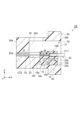
- FIG. 2 is a cross-sectional view of the equipment for holding optical fiber shown in FIG.
- FIG. 3 is a cross-sectional view of an optical fiber coupling structure including the optical fiber holding component of FIG.
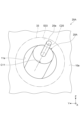
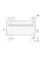
- FIG. 4 is a front view of the optical fiber coupling structure of FIG.
- FIG. 5 is a cross-sectional view for explaining an example of a method for manufacturing an optical fiber coupling structure.
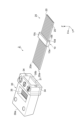
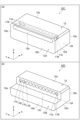
- FIG. 6 is an exploded perspective view of an optical connector including the optical fiber coupling structure of FIG.
- FIG. 7 is a perspective view of the optical connector of FIG.
- FIG. 8 is a cross-sectional view of the optical connector of FIG. FIG.
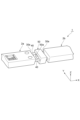
- FIG. 9 is a perspective view showing an optical coupling structure including a first optical connector and a second optical connector as optical connectors.
- FIG. 10 is a diagram for explaining a method for setting the inner diameter of the through hole of holding equipment for optical fiber.
- FIG. 11 is a front view of holding equipment for optical fiber of FIG.
- FIG. 12 is a diagram for explaining the problem of holding equipment for optical fiber according to the comparative example.
- FIG. 13 is a cross-sectional view of an optical connector according to the first modification.
- FIG. 14 is a diagram for explaining a method for setting the inner diameter of the through hole of the holding equipment for optical fiber included in the optical connector of FIG.
- FIG. 15 is a front view of holding equipment for optical fiber of FIG. FIG.
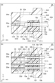
- FIG. 16a is a cross-sectional view of an optical connector according to the second modification.
- FIG. 16b is a plan view of the holding equipment for optical fiber provided in the optical connector of FIG. 16a.
- FIG. 17 is a perspective view showing another example of holding equipment for optical fiber of FIG. 16b.
- FIG. 18a is a cross-sectional view of an optical connector according to the third modification.
- FIG. 18b is a plan view of holding equipment for optical fiber provided in the optical connector of FIG. 18a.
- the optical fiber When the above-mentioned hole array is mounted on a ferrule, the optical fiber may be fixed in a tilted state in the holding hole of the hole array. In this case, even if the hole array is inserted straight into the inside of the ferrule, it is assumed that the tip of the optical fiber protruding from the hole array will hit the wall surface around the ferrule hole, making it impossible to insert the tip of the optical fiber into the ferrule hole. In response to this, for example, it is conceivable to shift the hole array up and down with respect to the ferrule, and forcibly insert the tip of the optical fiber into the ferrule hole while pressing the tip of the optical fiber against the inner surface of the ferrule hole.
- the tip of the optical fiber may come into strong contact with the inner surface of the ferrule hole, which may apply a large load to the optical fiber.
- a load may cause problems such as damage to the optical fiber or a decrease in optical transmission characteristics, and may be a factor in reducing the reliability of the optical fiber.
- the present disclosure provides an optical fiber holding component, an optical fiber coupling structure, an optical connector, an optical coupling structure, and a method for manufacturing an optical fiber coupling structure that can improve the reliability of optical fibers.
- An optical fiber holding component is an optical fiber holding component that is disposed inside a ferrule having multiple ferrule holes formed therein and holds multiple optical fibers that are inserted into the multiple ferrule holes, respectively.
- the optical fiber holding component includes a first surface and a second surface aligned in a first direction, and multiple through holes that penetrate between the first surface and the second surface in the first direction and are aligned in a second direction intersecting the first direction, corresponding to the multiple ferrule holes.
- Each of the multiple optical fibers includes an insertion portion that is inserted into and held in each of the multiple through holes, and a protrusion that protrudes from the through hole to the outside and is inserted into each of the multiple ferrule holes.
- the minimum value of the inner diameter of the through hole is equal to or greater than the maximum value of the outer diameter of the insertion portion.
- the insertion parts of the optical fibers are inserted and held in the through holes that penetrate between the first surface and the second surface in the first direction.
- the protruding parts of the optical fibers protrude from the through holes to the outside and are inserted into the ferrule holes.
- the tip of the protruding part is located inside the inner surface of the ferrule hole when viewed along the first direction, when the central axis of the optical fiber insertion part is inclined to the central axis of the through hole to the maximum inside the through hole.
- the protruding part can be reliably inserted into the ferrule hole without the tip of the protruding part hitting the inner surface of the ferrule hole or the wall surface surrounding the ferrule hole. This reduces the application of a large load to the optical fiber. As a result, the occurrence of problems such as damage to the optical fiber or deterioration of optical transmission characteristics can be reduced. Therefore, the optical fiber holding component described above makes it possible to increase the reliability of the optical fiber.
- the maximum value of the inner diameter of the through hole may be smaller than the maximum value of the inner diameter of the ferrule hole.
- the optical fiber may include a coating removal portion where part of the coating has been removed from the tip, and a coating portion where the coating remains.
- the coating removal portion and the coating portion only the coating removal portion may be inserted into the through hole as the insertion portion.
- the maximum value of the inner diameter of the through hole can be reduced to match the outer diameter of the coating removal portion, so that the inclination of the insertion portion inside the through hole can be reduced. Accordingly, the deviation of the tip of the protruding portion from the through hole can be reduced.
- the optical fiber holding component described in (3) above may further include a support portion that is disposed between the through hole and the second surface in the first direction and is capable of supporting a coating portion disposed outside the through hole.
- the coating portion of the optical fiber is supported by the support portion of the optical fiber holding component, so that the inclination of the insertion portion inside the through hole can be suppressed to a smaller extent. Accordingly, the deviation of the tip of the protruding portion from the through hole can be suppressed to a smaller extent.
- the optical fiber may include a coating removal portion where a part of the coating is removed from the tip, and a coating portion where the coating remains.
- the coating removal portion and the coating portion only the coating portion may be inserted into the through hole as an insertion portion.
- the maximum inner diameter of the through hole is set large in accordance with the outer diameter of the coating portion. Accordingly, the allowable range of deviation of the tip from the through hole to prevent the tip of the protrusion from contacting the inner surface of the ferrule hole becomes small. As a result, when the protrusion is inserted into the ferrule hole, the tip is likely to hit the inner surface of the ferrule hole, etc.
- the protrusion can be inserted more reliably into the ferrule hole without the tip hitting the inner surface of the ferrule hole, etc., when the optical fiber holding component is inserted into the ferrule.
- the through hole may include a constant diameter section having a constant inner diameter in a first direction capable of holding the insertion part, and an expanding diameter section formed between the constant diameter section in the first direction and the second surface, the inner diameter of which expands from the constant diameter section toward the second surface in the first direction.
- the tip of the optical fiber is guided to the constant diameter section by the expanding diameter section, so that the tip of the optical fiber can be reduced from coming into strong contact with the inner surface of the through hole, etc. This can more reliably reduce the application of a large load to the optical fiber.
- the through hole may be configured to hold the insertion part rotatably around the central axis of the insertion part.
- the rotational position of the optical fiber insertion part can be adjusted.
- the optical fiber insertion part is likely to tilt. Therefore, with the above configuration, the above-mentioned effects can be effectively achieved.
- the optical fiber may include at least one core in a region offset from the central axis of the optical fiber.
- the rotational position of the optical fiber insertion part can be adjusted. During this adjustment, the optical fiber insertion part is likely to tilt. Therefore, with the above configuration, the above-mentioned effects can be effectively achieved.
- the optical fiber holding component according to any one of (1) to (8) above may further include a third surface connecting the first surface and the second surface in the first direction, and a plurality of injection holes extending from the third surface so as to intersect with the plurality of through holes, individually communicating with each of the plurality of through holes, and capable of injecting adhesive for bonding the plurality of optical fibers to the plurality of through holes.
- the adhesive when fixing the optical fiber to the through hole using adhesive, the adhesive can be individually injected into the through hole from a route other than the through hole.
- An optical fiber coupling structure includes an optical fiber holding component according to any one of (1) to (9) above, and a plurality of optical fibers inserted into a plurality of through holes and fixed to the plurality of through holes by a hardened adhesive. Since this optical fiber coupling structure includes any one of the optical fiber holding components described above, the reliability of the optical fiber can be increased as described above.
- An optical connector includes the optical fiber coupling structure of (10) above, and a ferrule into which the optical fiber coupling structure is inserted.
- the protrusions of the multiple optical fibers are inserted into the multiple ferrule holes, respectively. Since this optical connector includes the optical fiber coupling structure described above, the reliability of the optical fiber can be increased, as described above.
- An optical coupling structure includes a first optical connector and a second optical connector as the optical connector of (11) above.
- the first optical connector and the second optical connector face each other across a gap in the first direction. Since this optical coupling structure includes the optical connectors described above, the reliability of the optical fiber can be improved as described above. Furthermore, in this way, when the first optical connector and the second optical connector are not connected by PC (Physical Contact), the pressing force for connecting the first optical connector and the second optical connector by PC is not required, so that it becomes possible to easily connect more optical fibers at once.
- PC Physical Contact
- a manufacturing method of an optical fiber coupling structure is a manufacturing method of the optical fiber coupling structure described in (10) above.
- This manufacturing method includes the steps of preparing an auxiliary optical fiber holding component and a fixed optical fiber holding component as optical fiber holding components, arranging the auxiliary optical fiber holding component in a first direction relative to the fixed optical fiber holding component, inserting an optical fiber in the first direction from the through hole of the fixed optical fiber holding component to the through hole of the auxiliary optical fiber holding component with the auxiliary optical fiber holding component and the fixed optical fiber holding component arranged in the first direction, injecting an adhesive into the through hole of the fixed optical fiber holding component and hardening the adhesive with the insertion portion of the optical fiber inserted into the through hole of the fixed optical fiber holding component and the protruding portion of the optical fiber inserted into the through hole of the auxiliary optical fiber holding component, and removing the auxiliary optical fiber holding component with the insertion portion fixed to the fixed optical fiber holding component.
- the auxiliary optical fiber holding component is used as a jig for regulating the position of the tip of the protruding part of the optical fiber protruding from the through hole of the fixed optical fiber holding component.
- the position of the tip of the protruding part is regulated by the inner surface of the through hole of the auxiliary optical fiber holding component, so that the position of the tip of the protruding part can be reduced from being significantly shifted to the outside of the through hole.
- the overall length of these optical fiber holding components in the first direction is increased. The longer this overall length, the smaller the inclination that may occur in the insertion part of the optical fiber inserted into the through hole of these optical fiber holding components.
- the auxiliary optical fiber holding component in the step of arranging the auxiliary optical fiber holding component in the first direction relative to the fixed optical fiber holding component, the auxiliary optical fiber holding component may be brought into contact with the fixed optical fiber holding component in the first direction so that the through hole of the auxiliary optical fiber holding component communicates with the through hole of the fixed optical fiber holding component in the first direction.
- the protruding portion of the optical fiber can be easily and reliably inserted into the through hole of the auxiliary optical fiber holding component.
- FIG. 1 is a perspective view of holding equipment for optical fiber 10 according to the present embodiment.
- FIG. 2(a) is a cross-sectional view of holding equipment for optical fiber 10.
- FIG. 2(b) is another cross-sectional view of holding equipment for optical fiber 10.
- Each figure shows an XYZ orthogonal coordinate system.
- the holding equipment for optical fiber 10 has a rectangular parallelepiped appearance with the Y direction (an example of the "second direction” in this disclosure) as the longitudinal direction, the X direction (an example of the "first direction” in this disclosure) as the transverse direction, and the Z direction as the thickness direction.
- the relative position of the Z coordinate may define "up and down”
- the relative position of the X coordinate may define “front and back”
- the relative position of the Y coordinate may define "left and right”. The larger the Z coordinate, the "up”. The larger the X coordinate, the "front”. The larger the Y coordinate, the "right”.
- the optical fiber holding component 10 is placed inside the ferrule 30 while holding multiple optical fibers 20 (see FIG. 7 described later).
- the optical fiber holding component 10 is made of a material such as quartz glass or a resin that is transparent to ultraviolet light and is used when curing an ultraviolet-curing adhesive. In this case, the optical fiber holding component 10 can be manufactured inexpensively and with high precision.
- the optical fiber holding component 10 may be made of metal, for example. In this case, high dimensional precision can be maintained, so the optical fiber holding component 10 can be manufactured with higher precision.
- the optical fiber holding component 10 is made of quartz glass or metal, frictional resistance between the optical fiber holding component 10 and multiple optical fibers 20 can be reduced.
- the optical fiber holding component 10 has, for example, a front surface 10a (an example of the "first surface” of the present disclosure), a rear surface 10b (an example of the "second surface” of the present disclosure), an upper surface 10c, a lower surface 10d, a side surface 10e, and a side surface 10f.
- the front surface 10a is an end surface located at the front end of the optical fiber holding component 10 in the X direction.
- the rear surface 10b is an end surface located at the rear end of the optical fiber holding component 10 in the X direction.
- the front surface 10a and the rear surface 10b are, for example, planes along the YZ plane, and are arranged side by side along the X direction.
- the normal direction of the front surface 10a coincides with the normal direction of the rear surface 10b, for example.
- the upper surface 10c is an end surface located at the upper end of the optical fiber holding component 10 in the Z direction.
- the lower surface 10d is an end surface located at the lower end of the optical fiber holding component 10 in the Z direction.
- the upper surface 10c and the lower surface 10d are, for example, planes along the XY plane, and are arranged on both sides of a plurality of through holes 11 described later in the Z direction.
- the upper surface 10c and the lower surface 10d connect the front surface 10a and the rear surface 10b in the X direction.
- the normal direction of the upper surface 10c coincides with the normal direction of the lower surface 10d, for example.
- the upper surface 10c and the lower surface 10d may be perpendicular to the front surface 10a and the rear surface 10b, for example.
- the side surface 10e is an end surface located at the first end of the optical fiber holding component 10 in the Y direction.
- the side surface 10f is, for example, an end surface located at the second end of the optical fiber holding component 10 in the Y direction.
- the side surfaces 10e and 10f are, for example, planes along the XZ plane, and are arranged on both sides of the multiple through holes 11 in the Y direction.
- the side surfaces 10e and 10f connect the front surface 10a and the rear surface 10b in the X direction.
- the normal direction of the side surface 10e coincides with, for example, the normal direction of the side surface 10f.
- the side surfaces 10e and 10f may be, for example, perpendicular to the front surface 10a, the rear surface 10b, the upper surface 10c, and the lower surface 10d.
- the optical fiber holding component 10 further includes a plurality of through holes 11 penetrating in the X direction from the front surface 10a to the rear surface 10b.
- Each through hole 11 extends, for example, along the X direction and is arranged in a row along the Y direction.
- Each through hole 11 is formed, for example, in a position closer to the upper surface 10c than to the lower surface 10d in the Z direction.
- 12 through holes 11 are arranged at equal intervals in a row (12 x 1 row) in the Y direction is illustrated.
- the number of through holes 11 is not limited to 12, and may be other numbers such as 4, 8, or 16.
- Each through hole 11 does not have to be arranged in a row, and may be arranged in two or more rows.
- FIG. 2A shows a cut surface of the optical fiber holding equipment 10 in the XY plane passing through the central axis C11 of each through hole 11.
- FIG. 2B shows a cut surface of the optical fiber holding equipment 10 in the XZ plane passing through the central axis C11 of each through hole 11.
- the central axis C11 is an axis passing through the center of the through hole 11 when the through hole 11 is cut on a plane perpendicular to the X direction.
- each through hole 11 extends linearly along the X direction, for example, and is arranged at equal intervals along the Y direction.
- Each through hole 11 is, for example, a circular shape centered on the central axis C11 when viewed along the X direction in which the central axis C11 extends.
- the inner diameter D11 of each through hole 11 is constant at each position along the X direction, for example.
- An opening 11a, which is the first end of each through hole 11, is formed on the front surface 10a.
- An opening 11b, which is the second end of each through hole 11, is formed on the rear surface 10b.
- FIG. 3A is a cross-sectional view of an optical fiber coupling structure 25 including an optical fiber holding component 10.
- FIG. 3B is another cross-sectional view of the optical fiber coupling structure 25.
- FIG. 4 is a front view of the optical fiber coupling structure 25.
- FIG. 3A and FIG. 3B show cut surfaces corresponding to FIG. 2A and FIG. 2B, respectively.
- the optical fiber coupling structure 25 includes the optical fiber holding component 10 and a plurality of optical fibers 20. When each optical fiber 20 is inserted into each through hole 11 of the optical fiber holding component 10, it is fixed to the inner surface of each through hole 11 by a hardened adhesive 60.
- the hardened adhesive 60 is, for example, a hardened ultraviolet (UV) curable resin.
- the hardened adhesive 60 may be a hardened thermosetting resin.
- the optical fiber 20 is, for example, an optical fiber that requires rotational alignment (i.e., adjustment of the position around the central axis C20).
- Each optical fiber 20 is, for example, a multi-core fiber (MCF: Multi Core Fiber).
- Each optical fiber 20 may be, for example, a polarization maintaining fiber (PMF: Polarization Maintaining Fiber).
- PMF Polarization Maintaining Fiber
- the optical fiber 20 has multiple cores 14a, a cladding 14b that covers the multiple cores 14a, and a coating 14c that surrounds the cladding 14b.
- At least one of the multiple cores 14a is arranged in a region other than the central axis C20, i.e., in a region shifted from the central axis C20.
- the central axis C20 is an axis that passes through the center of the optical fiber 20 when the optical fiber 20 is cut on a plane perpendicular to the X-direction.
- the optical fiber 20 includes a coating removal portion 22 and a coating portion 23.
- the coating removal portion 22 is a portion of the optical fiber 20 where a predetermined length of the coating 14c (see FIG. 4) has been removed from the tip surface 20a.
- the coating removal portion 22 includes multiple cores 14a and clad 14b. In the coating removal portion 22, the surface of the clad 14b is exposed to the outside.
- the coating portion 23 is a portion of the optical fiber 20 where the coating 14c remains.
- the coating portion 23 includes multiple cores 14a, clad 14b, and coating 14c.
- the outer diameter of the coating portion 23 is larger than the outer diameter of the coating removal portion 22 by the thickness of the coating 14c.
- the coating removal portion 22 includes, for example, an insertion portion 26 that is inserted and held in the through hole 11, and a protrusion 27 that protrudes from the through hole 11.
- the insertion portion 26 is, for example, an intermediate portion of the coating removal portion 22 that extends from the inner portion of the opening 11b of the through hole 11 to the inner portion of the opening 11a of the through hole 11.
- the protrusion 27 is, for example, a tip portion of the coating removal portion 22 that extends from the inner portion of the opening 11a to the tip surface 20a.
- the protrusion 27 is, for example, a portion of the coating removal portion 22 that protrudes forward from the front surface 10a where the opening 11a is formed.
- the protrusion 27 extends in the X direction outside the through hole 11 so as to move away from the through hole 11.
- the length L27 of the protruding portion 27 from the front surface 10a to the tip surface 20a along the X direction corresponds to the distance from the front surface 10a along the X direction to the front surface 30a of the ferrule 30 (see FIG. 7 described later).
- the length L26 of the insertion portion 26 from the front surface 10a to the rear surface 10b along the X direction corresponds to the length of the through hole 11 along the X direction. Therefore, the portion of the coating removal portion 22 from the rear end of the protruding portion 27 inside the opening 11a to a position spaced rearward by the length of the through hole 11 along the X direction is the insertion portion 26.
- the insertion portion 26 is inserted from the opening 11b into the through hole 11 in the X direction and fixed to the inner surface of the through hole 11 by the cured product 60 of the adhesive. This results in the insertion portion 26 being held in the through hole 11.
- the central axis C20 of the insertion portion 26 coincides with, for example, the central axis C11 of the through hole 11 (see FIG. 2(a)).
- the through hole 11 is configured to hold the insertion portion 26 rotatably around the central axis C20.
- the through hole 11 is configured to hold the insertion portion 26 rotatably around the central axis C20 means that the inner diameter D11 of the through hole 11 is set to be large enough to allow rotation of the insertion portion 26 around the central axis C20, and small enough to determine the position of the insertion portion 26 in the YZ plane.
- constant inner diameter includes both a completely constant inner diameter and an approximately constant inner diameter within the range of manufacturing error, etc.
- the inner diameter D11 of the through hole 11 is, for example, larger than the outer diameter of the insertion portion 26, i.e., the outer diameter D22 of the coating removal portion 22.
- the inner diameter D11 of the through hole 11 is set small so that the inclination of the insertion portion 26 inside the through hole 11 is small. A specific method for setting the inner diameter D11 of the through hole 11 will be described later.
- the entire insertion portion 26 is included in the coating removal portion 22. That is, of the coating removal portion 22 and the coating portion 23, only the coating removal portion 22 is inserted into and held in the through hole 11 as the insertion portion 26.
- the entire insertion portion 26 may be included in the coating portion 23. That is, of the coating removal portion 22 and the coating portion 23, only the coating portion 23 may be inserted into and held in the through hole 11 as the insertion portion 26.
- a part of the coating removal portion 22 and a part of the coating portion 23 may be included in the insertion portion 26. That is, both the coating removal portion 22 and the coating portion 23 may be inserted into and held in the through hole 11 as the insertion portion 26.
- the insertion portion 26 of the rotationally aligned optical fiber 20 is fixed inside the through hole 11 by the hardened adhesive 60.
- liquid adhesive is injected into the inside of the through hole 11 from the opening 11b on the rear surface 10b.
- the liquid adhesive fills the gap between the inner surface of the through hole 11 and the outer surface of the insertion portion 26.
- the liquid adhesive is hardened by, for example, irradiating it with ultraviolet light from outside the optical fiber holding component 10.
- an optical fiber coupling structure 25 is obtained in which each optical fiber 20 is held by the optical fiber holding component 10.
- the optical fiber coupling structure 25 From the viewpoint of reducing the positional deviation of the optical fiber 20 relative to the optical fiber holding component 10, it is also possible to prepare another optical fiber holding component and use the optical fiber holding component as a jig.
- An example of a manufacturing method of the optical fiber coupling structure 25 will be described below with reference to (a) to (c) of FIG. 5.
- FIG. 5 are cross-sectional views for explaining an example of a manufacturing method of an optical fiber coupling structure 25.
- an auxiliary optical fiber holding component 100 is prepared.
- the auxiliary optical fiber holding component 100 has, for example, the same configuration as the fixing optical fiber holding component 10.
- the auxiliary optical fiber holding component 100 is a jig that is temporarily used to regulate the position of each optical fiber 20 fixed to the fixing optical fiber holding component 10.
- the auxiliary optical fiber holding components 100 are arranged in the X direction relative to the fixed optical fiber holding components 10. Specifically, the rear surface 10b of the auxiliary optical fiber holding components 100 is brought into contact with the front surface 10a of the fixed optical fiber holding components 10 in the X direction so that each through hole 11 of the auxiliary optical fiber holding components 100 communicates with each through hole 11 of the fixed optical fiber holding components 10 in the X direction. In this state, for example, the central axis C11 of each through hole 11 of the auxiliary optical fiber holding components 100 coincides with the central axis C11 of each through hole 11 of the fixed optical fiber holding components 10 when viewed along the X direction.
- the rear surface 10b of the auxiliary optical fiber holding components 100 may be arranged with a gap in the X direction relative to the front surface 10a of the fixed optical fiber holding components 10.
- the optical fiber 20 is inserted in the X direction from the through hole 11 of the optical fiber holding component 10 for fixing to the through hole 11 of the auxiliary optical fiber holding component 100.
- the insertion portion 26 of the optical fiber 20 is inserted into the through hole 11 of the optical fiber holding component 10 for fixing, and the protrusion portion 27 of the optical fiber 20 is inserted into the through hole 11 of the auxiliary optical fiber holding component 100.
- the optical fiber 20 is inserted in a tilted state relative to the through hole 11 of the optical fiber holding component 10 for fixing.
- the insertion portion 26 extends in a tilted direction from the central axis C11 inside the through hole 11 of the optical fiber holding component 10 for fixing and contacts the inner surface of the through hole 11.
- the insertion portion 26 is bent at the contact position P11 with the inner surface of the through hole 11, and then extends linearly in the X direction along the inner surface of the through hole 11.
- the protrusion 27 extends linearly in the X direction along the inner surface of the through hole 11 inside the through hole 11 of the auxiliary optical fiber holding component 100.
- liquid adhesive is injected into the through hole 11 of the fixing optical fiber holding component 10, and the insertion portion 26 is fixed to the inner surface of the through hole 11 by the hardened adhesive 60. At this time, no adhesive is injected into the through hole 11 of the auxiliary optical fiber holding component 100, and the protrusion 27 is not fixed to the inner surface of the through hole 11 of the auxiliary optical fiber holding component 100.
- the auxiliary optical fiber holding component 100 is removed to obtain an optical fiber coupling structure 25 in which the optical fiber 20 is held by the fixing optical fiber holding component 10.
- the auxiliary optical fiber holding component 100 when used as a jig to regulate the position of the tip surface 20a of the protrusion 27 of the optical fiber 20 protruding from the through hole 11 of the fixing optical fiber holding component 10 during the manufacturing process of the optical fiber coupling structure 25, the position of the tip surface 20a of the protrusion 27 is regulated by the inner surface of the through hole 11 of the auxiliary optical fiber holding component 100, thereby reducing the position of the tip surface 20a of the protrusion 27 from shifting significantly radially outward from the through hole 11.
- the overall length of these optical fiber holding components 10, 100 in the X direction can be increased.
- the longer the overall length of the optical fiber holding components 10, 100 the smaller the inclination that may occur in the insertion part 26 of the optical fiber 20 inserted into the through hole 11 of the optical fiber holding components 10, 100.
- the protrusion 27 of the optical fiber 20 can be easily and reliably inserted into the through hole 11 of the auxiliary optical fiber holding component 100 when inserting the optical fiber 20 from the through hole 11 of the fixed optical fiber holding component 10 to the through hole 11 of the auxiliary optical fiber holding component 100, compared to when the auxiliary optical fiber holding component 100 is arranged with a gap from the fixed optical fiber holding component 10.
- auxiliary optical fiber holding components 100 may be two or more.
- two auxiliary optical fiber holding components may be arranged in the X direction in front of or behind the fixed optical fiber holding component 10.
- two auxiliary optical fiber holding components may be arranged on both sides of the fixed optical fiber holding component 10 in the X direction.
- an injection hole for injecting adhesive may be formed on the upper surface 10c of the fixed optical fiber holding component 10. The injection hole may extend from the upper surface 10c in the Z direction and communicate with the through hole 11.
- the optical fiber 20 can be fixed to the inner surface of the through hole 11 by the adhesive injected from the upper surface 10c through the injection hole into the through hole 11.
- the overall length of these optical fiber holding components in the X direction can be increased. Accordingly, the inclination that may occur in the insertion portion 26 of the optical fiber 20 inserted into the through hole 11 of these optical fiber holding components can be reduced. As a result, when inserting the optical fiber 20 held by the fixing optical fiber holding component 10 into the inside of the ferrule 30, it is possible to more reliably insert the protrusion 27 into the ferrule hole 33 without the tip surface 20a of the optical fiber 20 hitting hard against the inner surface of the ferrule hole 33, etc.
- FIG. 6 is an exploded perspective view of the optical connector 2 including the optical fiber coupling structure 25 described above.
- FIG. 7 is a perspective view of the optical connector 2 of FIG. 6.
- the optical connector 2 includes, for example, the optical fiber coupling structure 25 described above and a ferrule 30. As shown in FIGS. 6 and 7, the ferrule 30 has, for example, a substantially rectangular parallelepiped appearance.
- the optical fiber coupling structure 25 is inserted into the inside of the ferrule 30 and fixed inside the ferrule 30.
- the optical connector 2 may include, for example, two optical fiber coupling structures 25. In this case, the two optical fiber coupling structures 25 may be inserted into the ferrule 30 in a state where they are stacked on top of each other in the Z direction so that their upper surfaces 10c, 10c face each other.
- FIG. 8A is a cross-sectional view of the optical connector 2.
- FIG. 8B is another cross-sectional view of the optical connector 2.
- the ferrule 30 has a front surface 30a located at the front end in the X direction and a rear surface 30b located at the rear end in the X direction.
- the front surface 30a is, for example, a surface that is flush with the tip surface 20a of each optical fiber 20 without any steps.
- the rear surface 30b has an opening 31 that can receive the optical fiber coupling structure 25.
- a pair of guide holes 34, 34 are formed in the ferrule 30, but in FIG. 8B, the pair of guide holes 34, 34 are omitted for convenience.
- the pair of guide holes 34, 34 are holes that penetrate the ferrule 30 in the X direction from the front surface 30a to the rear surface 30b.
- the ferrule 30 has a receiving hole 32 and a plurality of ferrule holes 33 inside.
- the receiving hole 32 is a hole extending in the X direction from the opening 31.
- the receiving hole 32 holds the optical fiber coupling structure 25 introduced from the opening 31.
- the receiving hole 32 includes, for example, an inner surface 32a, a pair of inner surfaces 32b, 32b, an inner surface 32c, an inner surface 32d, and an inner surface 32e.
- the inner surface 32a extends, for example, along the XY plane.
- the pair of inner surfaces 32b, 32b extend, for example, along the XZ plane, and are disposed on both sides of the inner surface 32a in the Y direction.
- the pair of inner surfaces 32b, 32b are formed, for example, perpendicular to the inner surface 32a.
- the inner surface 32c extends along the YZ plane and extends upward from the inner surface 32a along the Z direction.
- the inner surface 32c faces the opening 31 in the X direction.
- the inner surface 32c is formed perpendicular to the inner surface 32a.
- the inner surface 32d extends, for example, along the YZ plane and is recessed forward from the inner surface 32c.
- the inner surface 32d extends, for example, parallel to the inner surface 32c.
- the inner surface 32e extends along the XY plane so as to connect the inner surfaces 32c and 32d in the X direction.
- the inner surface 32e has, for example, a number of V-grooves 32f formed therein, each of which corresponds to a number of ferrule holes 33.
- the ferrule holes 33 penetrate in the X direction from the inner surface 32d to the front surface 30a.
- the ferrule holes 33 are arranged in a line in the Y direction to correspond to the optical fibers 20 arranged in a line in the Y direction.
- the protrusion 27 of each optical fiber 20 extending forward from the optical fiber coupling structure 25 is inserted into each ferrule hole 33.
- the inner diameter D33 of the ferrule hole 33 is, for example, larger than the outer diameter of the protrusion 27, i.e., the outer diameter D22 of the coating removal portion 22.
- a window 35 for injecting adhesive is formed on the upper surface of the ferrule 30.
- the cured adhesive is omitted in FIG. 8A and FIG. 8B, the cured adhesive may be the same as the cured adhesive 60 described above.
- the lower surface 10d of the optical fiber coupling structure 25 contacts the inner surface 32a. This determines the Z-direction position of the optical fiber coupling structure 25 relative to the ferrule 30. Furthermore, as shown in FIG. 8(b), the side surfaces 10e and 10f of the optical fiber coupling structure 25 contact the pair of inner surfaces 32b, 32b, respectively. This determines the Y-direction position of the optical fiber coupling structure 25 relative to the ferrule 30.
- the central axis C11 of each through hole 11 of the optical fiber holding component 10 coincides with the central axis C33 of each ferrule hole 33 when viewed along the X direction. Furthermore, the front surface 10a of the optical fiber coupling structure 25 abuts against the inner surface 32c in the X direction, thereby determining the X direction position of the optical fiber coupling structure 25 relative to the ferrule 30. Then, adhesive is injected through the window 35, and the optical fiber coupling structure 25 is fixed to the ferrule 30 by the hardened adhesive. This results in the optical connector 2 being obtained.
- Figure 9 is a perspective view showing an optical coupling structure 1 having a first optical connector 2a and a second optical connector 2b as the optical connectors 2.
- the front surface 30a of the first optical connector 2a and the front surface 30a of the second optical connector 2b face each other in the X direction with a gap between them.
- a pair of guide pins 40, 40 fit into a pair of guide holes 34, 34 of the first optical connector 2a and a pair of guide holes 34, 34 of the second optical connector 2b. This defines the positions of the first optical connector 2a and the second optical connector 2b in the YZ plane.
- a spacer 50 is disposed between the front surface 30a of the first optical connector 2a and the front surface 30a of the second optical connector 2b.
- the spacer 50 is a plate-shaped member having an opening 50a.
- the opening 50a allows a plurality of optical paths extending between the first optical connector 2a and the second optical connector 2b to pass through.
- the spacer 50 abuts against the front surface 30a of the first optical connector 2a and the front surface 30a of the second optical connector 2b in the X direction, thereby defining the gap between the first optical connector 2a and the second optical connector 2b in the X direction.
- FIG. 10 and Fig. 11 are diagrams for explaining the setting method of the inner diameter D11 of the through hole 11.
- Fig. 10 and Fig. 11 are diagrams for explaining the setting method of the inner diameter D11 of the through hole 11.
- the outer diameter D22 of the coating removal part 22 of the optical fiber 20 is represented as "A”
- the inner diameter D11 of the through hole 11 is represented as “B”
- the inner diameter D33 of the ferrule hole 33 is represented as "C”
- the length of the through hole 11 along the X direction i.e., the length L26 of the insertion part 26 along the X direction is represented as "D”
- the length L27 of the protrusion part 27 along the X direction is represented as "d”.
- FIG. 10 shows a cross section of the optical fiber coupling structure 25 when the insertion portion 26 of the optical fiber 20 is inclined to the maximum inside the through hole 11 in a state where the central axis C11 of the through hole 11 coincides with the central axis C33 of the ferrule hole 33 when viewed along the X direction.
- the state where the central axis C11 of the through hole 11 coincides with the central axis C33 of the ferrule hole 33 when viewed along the X direction means a state where the through hole 11 and the ferrule hole 33 are arranged in the X direction so that the extension line of the central axis C11 coincides with the central axis C33.
- the state where the insertion portion 26 is inclined to the maximum means a state where the angle ⁇ between the central axis C20 of the insertion portion 26 inserted into the through hole 11 and the central axis C11 of the through hole 11 is maximum.
- the angle ⁇ is maximum when the insertion portion 26 contacts the upper end of the opening 11a while contacting the lower end of the opening 11b.
- the inner diameter B is represented by the sum of the length L1 and the length L2.
- the length L1 indicates the length in the Z direction of the region inside the opening 11a that is occupied by the insertion portion 26.
- the length L2 indicates the length in the Z direction of the region inside the opening 11a that is not occupied by the insertion portion 26. Since the length L1 is geometrically represented by the following formula (1), the length L2 is represented by the following formula (2). Therefore, the following relational expression (3) is obtained with respect to the angle ⁇ .
- the distance in the X direction from the front surface 10a to the upper end of the tip surface 20a is represented as L3, the distance L3 is geometrically represented by the following formula (4). Therefore, if the amount of deviation of the tip surface 20a from the inner surface of the through hole 11 in the Z direction is represented as L4, the deviation amount L4 is geometrically represented by the following formula (5). If the amount of deviation between the inner diameter B and the inner diameter C is represented as L5, the deviation amount L5 is represented by the following formula (6). In order to insert the optical fiber 20 into the ferrule hole 33 so that the tip surface 20a does not contact the inner surface S33 of the ferrule hole 33, it is sufficient that the deviation amount L4 of the tip surface 20a is smaller than the deviation amount L5.
- the deviation amount L5 indicates the allowable range of the deviation amount L4 for the tip surface 20a not to contact the inner surface S33 of the ferrule hole 33.
- the condition for inserting the optical fiber 20 into the ferrule hole 33 without bringing the tip face 20a into contact with the inner surface S33 of the ferrule hole 33 is L4 ⁇ L5.
- the condition that the inner diameter B should satisfy is expressed as the following formula (8).
- the upper limit of the inner diameter B By setting the upper limit of the inner diameter B in this way, it becomes possible to insert the optical fiber 20 into the ferrule hole 33 without contacting the tip surface 20a with the inner surface S33 of the ferrule hole 33.
- the inner diameter B is not constant at each position of the through hole 11 along the X direction, it is sufficient that the maximum value of the inner diameter B satisfies the upper limit of the inner diameter B shown in formula (8).
- the maximum value of the inner diameter B may be smaller than the maximum value of the inner diameter C, for example.
- the ferrule hole 33 has a diameter expanding portion that expands as it approaches the inner surface 32c, the inner diameter of the opening of the ferrule hole 33 at the inner surface 32c becomes the maximum. Therefore, the maximum value of the inner diameter C in this case becomes the inner diameter of the opening of the ferrule hole 33 at the inner surface 32c.
- the outer diameter A in formula (7) when the outer diameter A is not constant at each position of the coating removal portion 22 along the X direction, it is sufficient that the maximum value of the outer diameter A satisfies the lower limit condition of the inner diameter B shown in formula (8). In other words, it is sufficient that the minimum value of the inner diameter B is larger than the maximum value of the outer diameter A.
- the outer diameter A is 125 ⁇ m
- the inner diameter C is 200 ⁇ m
- the length D is 1.5 mm
- the length d is 6.5 mm
- substituting these values into equation (8) gives the relational equation 125 ⁇ m ⁇ B ⁇ 132.8 ⁇ m.
- the angle ⁇ is considered to be infinitesimally small, and is approximated as sin ⁇ ⁇ 0 and cos ⁇ ⁇ 1.
- the maximum value of the inner diameter B may be, for example, smaller than 132.8 ⁇ m.
- FIG. 11 shows a front view of the front surface 10a of the optical fiber coupling structure 25 of FIG. 10.
- the inner surface S33 of the ferrule hole 33 is shown by a two-dot chain line.
- the tip face 20a being located inside the inner surface S33 when viewed along the X direction means that the entire tip face 20a is contained within the area inside the inner surface S33 when viewed along the X direction.
- the tip face 20a may be separated from the inner surface S33 without overlapping with the inner surface S33 when viewed along the X direction.
- the relationship between the inner diameter B and the length d shown in the above formula (8) can be explained as follows.
- the length d of the protrusion 27 is relatively short (i.e., when the optical fiber holding equipment 10 is arranged near the ferrule hole 33)
- the inclination of the protrusion 27 is reduced, so the inner diameter B can be made larger.
- the inner diameter B can be made larger, it becomes easier to insert the protrusion 27 into the ferrule hole 33 without the tip surface 20a of the optical fiber 20 strongly hitting the inner surface S33 of the ferrule hole 33.
- the inner diameter B is large, it becomes possible to relax the manufacturing accuracy of the through hole 11 of the optical fiber holding equipment 10.
- the length d of the protrusion 27 is relatively long (i.e., when the optical fiber holding equipment 10 is arranged at a position far from the ferrule hole 33), the inclination of the protrusion 27 becomes large, so it is required to make the inner diameter B small.
- the length d of the protrusion 27 it becomes possible to distribute the bending stress applied to the protrusion 27 when the optical fiber 20 is inserted into the through hole 11.
- the outer diameter A 125 ⁇ m
- the inner diameter C 200 ⁇ m
- the length D 1.5 mm
- the total length of the ferrule 30 is 8 mm
- the maximum value of the inner diameter B may be, for example, smaller than 157.1 ⁇ m, smaller than 136.8 ⁇ m, or smaller than 132.8 ⁇ m.
- optical fiber holding component 10 optical fiber coupling structure 25, optical connector 2, optical coupling structure 1, and manufacturing method of the optical fiber coupling structure 25 according to the present embodiment described above will be explained together with the problems of the comparative example.
- the optical fiber holding component 110 has a through hole 111 for holding the optical fiber 120.
- the optical fiber 120 may be inserted into the through hole 111 in a significantly tilted state, and the optical fiber 120 may be fixed to the inner surface of the through hole 111 by the hardened adhesive 160 in that state.
- the tip surface 120a of the optical fiber 120 may be significantly shifted to the outside of the through hole 111.
- the maximum value of the inner diameter D11 of the through hole 11 may be smaller than the maximum value of the inner diameter D33 of the ferrule hole 33.
- the coating removal portion 22 may be inserted into the through hole 11 as the insertion portion 26.
- the maximum value of the inner diameter D11 of the through hole 11 can be reduced to match the outer diameter D22 of the coating removal portion 22, so the inclination of the insertion portion 26 inside the through hole 11 can be kept small. Accordingly, the deviation of the tip surface 20a of the protruding portion 27 from the through hole 11 can be kept small.
- the optical fiber holding component 10 when inserting the optical fiber holding component 10 into the inside of the ferrule 30, it is possible to more reliably insert the protruding portion 27 into the ferrule hole 33 without the tip surface 20a strongly hitting against the inner surface S33 of the ferrule hole 33, etc.
- the optical fiber 20 may include at least one core 14a in a region offset from the central axis C20 of the optical fiber 20.
- the through hole 11 may be configured to hold the insertion portion 26 rotatably around the central axis C20 of the insertion portion 26. In this case, the rotational position of the insertion portion 26 of the optical fiber 20 can be adjusted. During this adjustment, the insertion portion 26 of the optical fiber 20 is likely to tilt. Therefore, with the above configuration, the above-mentioned effects can be effectively achieved.
- optical fiber holding components, optical fiber coupling structures, optical connectors, optical coupling structures, and methods for manufacturing optical fiber coupling structures disclosed herein are not limited to the above-described embodiments, and may be modified as appropriate without departing from the spirit of the claims.
- FIG. 13(a) is a cross-sectional view of the optical connector 2A according to the first modification.
- FIG. 13(b) is another cross-sectional view of the optical connector 2A.
- the difference between the optical connector 2A and the optical connector 2 described above is that only the coating part 23 of the optical fiber 20 is inserted into the through hole 11A of the holding equipment for optical fiber 10A as the insertion part 26A.
- the inner diameter D11A of the through hole 11A is set larger than the outer diameter D23 of the coating part 23.
- the coating removal part 22 and the end of the coating part 23 protrude to the outside from the through hole 11A as the protrusion part 27A.
- the receiving hole 32A of the ferrule 30A further includes an inner surface 32g in addition to the configuration of the receiving hole 32 described above.
- the inner surface 32g is disposed between the inner surface 32e and the inner surface 32a in the X direction, and extends along the XY plane.
- the inner surface 32g forms a step recessed in the Z direction with respect to the inner surface 32e.
- the inner surface 32g faces the end of the covering portion 23 included in the protruding portion 27A in the Z direction.
- FIGs. 14 and 15 are diagrams for explaining a method for setting the inner diameter D11A of the through hole 11A.
- the outer diameter D22 of the coating removal portion 22 of the optical fiber 20 is represented as "A”
- the inner diameter D11A of the through hole 11A is represented as “B”
- the inner diameter D33 of the ferrule hole 33 is represented as "C”
- the length of the through hole 11A along the X direction i.e., the length L26 of the insertion portion 26A along the X direction
- the length L27 of the protrusion 27A along the X direction is represented as "d”
- the outer diameter D23 of the coating portion 23 of the optical fiber 20 is represented as "E”.
- the inner diameter B is represented by the sum of the length L1 and the length L2. Since the length L1 and the length L2 are respectively represented as the above-mentioned formula (1) and formula (2), the relational expression of the above-mentioned formula (3) is obtained with respect to the angle ⁇ .
- the distance in the X direction from the front surface 10a to the upper end of the tip surface 20a is represented as L3, the distance L3 is represented by the above-mentioned formula (4). If the amount of deviation of the tip surface 20a in the Z direction from the inner surface of the through hole 11A is represented as L4, the deviation amount L4 is represented by the above-mentioned formula (5).
- the amount of deviation between the outer diameter E of the coated portion 23 and the outer diameter A of the coating removal portion 22 is represented as L5
- the amount of deviation L5 is expressed as in the following formula (9)
- the length L6 is geometrically represented as in the following formula (10).
- the amount of deviation L7 can be obtained by subtracting the length L6 from the amount of deviation L4, and therefore the following formula (11) is obtained.
- the amount of deviation between the inner diameter B and the inner diameter C is represented as L8, the amount of deviation L8 is represented by the following formula (12).
- the deviation L7 of the tip face 20a is smaller than the deviation L8. Therefore, the deviation L8 indicates the allowable range of the deviation L7 for the tip face 20a not coming into contact with the inner surface S33 of the ferrule hole 33.
- the condition for inserting the optical fiber 20 into the ferrule hole 33 without the tip face 20a coming into contact with the inner surface S33 of the ferrule hole 33 is L7 ⁇ L8. When this condition is expressed using formulas (11) and (12), the following formula (13) is obtained.
- the condition that the inner diameter B should satisfy is expressed as the following formula (14).
- the upper limit of the inner diameter B By setting the upper limit of the inner diameter B in this manner, it is possible to insert the optical fiber 20 into the ferrule hole 33 without contacting the tip face 20a with the inner surface S33 of the ferrule hole 33.
- the inner diameter B is not constant at each position of the through hole 11A along the X direction, it is sufficient that the maximum value of the inner diameter B satisfies the upper limit condition of the inner diameter B shown in formula (14).
- the maximum value of the inner diameter B may be smaller than, for example, 216.6 ⁇ m.
- the outer diameter E in formula (14) when the outer diameter E is not constant at each position of the coating portion 23 along the X direction, it is sufficient that the maximum value of the outer diameter E satisfies the lower limit condition of the inner diameter B shown in formula (14). In other words, it is sufficient that the minimum value of the inner diameter B is equal to or greater than the maximum value of the outer diameter E.
- the minimum value of the inner diameter B may be the same as the maximum value of the outer diameter E.
- FIG. 15 shows a front view of the front surface 10a of the optical fiber coupling structure 25A of FIG. 14.
- the inner surface S33 of the ferrule hole 33 is shown by a two-dot chain line.
- the tip face 20a being located inside the inner surface S33 when viewed along the X direction means that the entire tip face 20a is contained within the area inside the inner surface S33 when viewed along the X direction.
- the tip face 20a may be separated from the inner surface S33 without overlapping with the inner surface S33 when viewed along the X direction.
- the outer diameter A 125 ⁇ m
- the inner diameter C 230 ⁇ m
- the length D 1.5 mm
- the outer diameter E 200 ⁇ m
- the total length of the ferrule 30A is 8 mm
- the length d of the protruding part 27A By setting the length d of the protruding part 27A in this way, it is possible to effectively obtain the following effects: the risk of contacting the optical fiber 20 with the inner surface S33 of the ferrule hole 33 when inserting the optical fiber holding equipment 10A into the ferrule 30A can be reduced; the manufacturing precision of the through hole 11A of the optical fiber holding equipment 10A can be relaxed; and the bending stress on the protruding part 27A when inserting the optical fiber 20 into the through hole 11A can be dispersed.
- the maximum value of the inner diameter B may be, for example, smaller than 210.9 ⁇ m or smaller than 216.6 ⁇ m.
- the same effect as the above-mentioned embodiment can be achieved.
- the covering portion 23 is inserted into the through hole 11A as the insertion portion 26A.
- the maximum value of the inner diameter D11A of the through hole 11A is set large to match the outer diameter D23 of the covering portion 23. Accordingly, the allowable range of deviation of the tip surface 20a from the through hole 11A to prevent the tip surface 20a of the protrusion 27A from contacting the inner surface of the ferrule hole 33 becomes smaller.
- the larger the inner diameter B the smaller the deviation amount L8, which is the allowable range of the deviation amount L7.
- the protrusion 27A when the protrusion 27A is inserted into the ferrule hole 33, the tip surface 20a is likely to abut against the inner surface S33 of the ferrule hole 33, etc.
- the protrusion 27A can be reliably inserted into the ferrule hole 33 without the tip surface 20a strongly hitting the inner surface S33 of the ferrule hole 33, so the application of a large load to the optical fiber 20 can be more effectively reduced.
- Fig. 16a is a cross-sectional view of the optical connector 2B according to the modified example 2.
- Fig. 16b is a plan view of holding equipment for optical fiber 10B that the optical connector 2B has. The difference between the optical connector 2B and the optical connector 2 described above is the configuration of holding equipment for optical fiber 10B.
- holding equipment for optical fiber 10B has a support part 12 that supports the coating removal part 22 of a plurality of optical fibers 20, and a support part 13 that supports the coating part 23 of a plurality of optical fibers 20.
- the support portion 12 includes a plurality of through holes 11B into which the coating removal portions 22 of the plurality of optical fibers 20 are respectively inserted as insertion portions 26.
- Each through hole 11B includes, for example, a fixed diameter portion 11c and an expanded diameter portion 11d.
- the fixed diameter portion 11c extends linearly in the X direction from the front surface 10a to the rear surface 10b.
- the inner diameter of the fixed diameter portion 11c is constant at each position along the X direction of the fixed diameter portion 11c.
- the expanded diameter portion 11d extends linearly in the X direction from the fixed diameter portion 11c to the support portion 13.
- the inner diameter of the expanded diameter portion 11d is set to gradually increase from the fixed diameter portion 11c toward the support portion 13 in the X direction.
- the fixed diameter portion 11c has an inner diameter into which the coating removal portion 22 of the optical fiber 20 can be inserted.
- the fixed diameter portion 11c is configured to hold the coating removal portion 22 rotatably around the central axis C20 of the optical fiber 20.
- the fixed diameter portion 11c being configured to hold the coating removal portion 22 rotatably around the central axis C20 means that the inner diameter of the fixed diameter portion 11c is set to be large enough to allow rotation of the coating removal portion 22 around the central axis C20, and small enough to define the position of the coating removal portion 22 in the YZ plane.
- the support portion 13 is disposed between the support portion 12, in which the multiple through holes 11B are formed, and the rear surface 10b in the X direction.
- the support portion 13 supports the coating portion 23 of the optical fiber 20 disposed outside the through hole 11B.
- the support portion 13 includes, for example, multiple fixing holes 13a that penetrate from the rear surface 10b in the X direction and communicate with the multiple through holes 11B.
- Each fixing hole 13a extends linearly in the X direction from the rear surface 10b toward the constant diameter portion 11c.
- the fixing hole 13a has an inner diameter that allows the coating portion 23 of the optical fiber 20 to be inserted.
- the fixing hole 13a is configured to hold the coating portion 23 rotatably around the central axis C20.
- the inner diameter of the fixing hole 13a is set to be large enough to allow rotation of the coating portion 23 around the central axis C20, and small enough to define the position of the coating portion 23 in the YZ plane.
- the inner diameter of the fixing hole 13a is constant at each position along the X direction.
- the inner diameter of the fixing hole 13a may be equal to or greater than the outer diameter of the covering portion 23.
- the optical fiber holding equipment 10B is provided with a support part 13 capable of supporting the coating part 23.
- the coating part 23 of the optical fiber 20 is supported by the support part 13 of the optical fiber holding equipment 10B, so that the inclination of the insertion part 26 inside the through hole 11B can be suppressed to a smaller extent. Accordingly, the deviation of the tip surface 20a of the protruding part 27 from the through hole 11B can be suppressed to a smaller extent.
- the through hole 11B includes a fixed diameter section 11c and an expanded diameter section 11d.
- the tip surface 20a of the optical fiber 20 is guided into the fixed diameter section 11c by the expanded diameter section 11d, which reduces the tip surface 20a of the optical fiber 20 from coming into strong contact with the inner surface of the through hole 11B, etc. This more reliably reduces the application of a large load to the optical fiber 20.
- FIG. 17 is a perspective view of an optical fiber holding component 10C, which is another example of the optical fiber holding component 10B.
- the optical fiber holding component 10C includes a support part 13A including one fixing hole 13b, instead of the support part 13 including multiple fixing holes 13a.
- the fixing hole 13b has an elliptical shape that includes all the through holes 11B when viewed along the X direction.
- the fixing hole 13b is connected to the multiple through holes 11B in the X direction.
- the coating parts 23 of the optical fibers 20 are inserted together into the fixing holes 13b.
- FIG. 17 is a perspective view of an optical fiber holding component 10D, which is yet another example of the optical fiber holding component 10B.
- the optical fiber holding component 10D includes a supporting part 13B including a supporting surface 13c instead of the supporting part 13 including a plurality of fixing holes 13a.
- the supporting surface 13c is, for example, a plane along the XY plane, and forms a step with respect to the upper surface 10c.
- the supporting surface 13c is disposed at a position shifted toward the lower surface 10d side from the through hole 11B in the Z direction.
- the supporting surface 13c supports the covering part 23 disposed outside the through hole 11B in the Z direction.
- FIG. 18a is a cross-sectional view of an optical connector 2C according to the third modification.
- FIG. 18b is a plan view of holding equipment for optical fiber 10E included in the optical connector 2C.
- the optical connector 2C is different from the above-mentioned optical connector 2 in that holding equipment for optical fiber 10E includes a plurality of injection holes 15.
- each injection hole 15 is a hole extending from the upper surface 10c in the Z direction.
- each injection hole 15 is arranged in a line in the Y direction corresponding to each through hole 11.
- Each injection hole 15 is, for example, circular when viewed along the Z direction, and is arranged so as to overlap with the through hole 11 in the Z direction.
- Each injection hole 15 for example, penetrates linearly from the upper surface 10c to each through hole 11 in the Z direction, and communicates with each through hole 11 individually. That each injection hole 15 is individually connected to each through hole 11 means that one injection hole 15 is connected to one through hole 11, and that one injection hole 15 is not connected to two or more through holes 11. Therefore, each injection hole 15 is provided independently for each through hole 11, and adhesive injected into one injection hole 15 is introduced only into one through hole 11 connected to that injection hole 15.
- the inner diameter of the injection hole 15 has a size that allows liquid adhesive injected from the top surface 10c to be introduced into the through holes 11.
- the size that allows liquid adhesive to be introduced into the through holes 11 means a size that allows the liquid adhesive to flow through the injection hole 15 and reach the through holes 11.
- the inner diameter of the injection hole 15 is set to be smaller than the pitch of each through hole 11.
- the inner diameter of the injection hole 15 may be smaller than the inner diameter of the through holes 11 or may be larger than the inner diameter of the through holes 11, as long as the adhesive can be introduced into the through holes 11.
- the inner diameter of the injection hole 15 may be the same as the inner diameter of the through holes 11.
- the adhesive can be individually injected into the through hole 11 from a route other than the through hole 11.
- the adhesive can be reliably filled between the optical fiber 20 and the through hole 11 without any gaps. This allows the adhesive to be distributed evenly around the optical fiber 20, so that the stress generated when the adhesive hardens can be applied uniformly to the optical fiber 20.
- the present disclosure is not limited to the above-described embodiments and modifications, and various other modifications are possible.
- the above-described embodiments and modifications may be combined with each other to the extent that there is no contradiction, depending on the required purpose and effect.
- the configuration of the optical fiber holding component is not limited to the above-described embodiments and modifications.
- the through holes may also be arranged in two rows corresponding to the arrangement of the multiple optical fibers.
- the inner diameter of the through hole of the optical fiber holding component does not need to be constant at each position along the through hole, and may vary at each position along the through hole. Both the coating removal portion and the coating portion of the optical fiber may be inserted into the through hole of the optical fiber holding component.
Landscapes
- Physics & Mathematics (AREA)
- General Physics & Mathematics (AREA)
- Optics & Photonics (AREA)
- Mechanical Coupling Of Light Guides (AREA)
Priority Applications (3)
| Application Number | Priority Date | Filing Date | Title |
|---|---|---|---|
| CN202480041276.6A CN121359061A (zh) | 2023-06-23 | 2024-05-27 | 光纤保持部件、光纤耦合结构体、光连接器、光耦合结构以及光纤耦合结构体的制造方法 |
| JP2025527626A JPWO2024262254A1 (https=) | 2023-06-23 | 2024-05-27 | |
| EP24825661.2A EP4733821A1 (en) | 2023-06-23 | 2024-05-27 | Optical fiber holding component, optical fiber coupling structure, optical connector, optical coupling structure, and method for manufacturing optical fiber coupling structure |
Applications Claiming Priority (2)
| Application Number | Priority Date | Filing Date | Title |
|---|---|---|---|
| JP2023103573 | 2023-06-23 | ||
| JP2023-103573 | 2023-06-23 |
Publications (1)
| Publication Number | Publication Date |
|---|---|
| WO2024262254A1 true WO2024262254A1 (ja) | 2024-12-26 |
Family
ID=93935061
Family Applications (1)
| Application Number | Title | Priority Date | Filing Date |
|---|---|---|---|
| PCT/JP2024/019398 Ceased WO2024262254A1 (ja) | 2023-06-23 | 2024-05-27 | 光ファイバ保持部品、光ファイバ結合構造体、光コネクタ、光結合構造、および光ファイバ結合構造体の製造方法 |
Country Status (4)
| Country | Link |
|---|---|
| EP (1) | EP4733821A1 (https=) |
| JP (1) | JPWO2024262254A1 (https=) |
| CN (1) | CN121359061A (https=) |
| WO (1) | WO2024262254A1 (https=) |
Citations (8)
| Publication number | Priority date | Publication date | Assignee | Title |
|---|---|---|---|---|
| JPH09203823A (ja) * | 1996-01-24 | 1997-08-05 | Furukawa Electric Co Ltd:The | 光コネクタ |
| JP2004045751A (ja) * | 2002-07-11 | 2004-02-12 | Sumitomo Electric Ind Ltd | 多心光コネクタ |
| WO2018135368A1 (ja) | 2017-01-17 | 2018-07-26 | 住友電気工業株式会社 | 光ファイバ保持部品、光コネクタ、及び光結合構造 |
| US20180314012A1 (en) * | 2015-10-21 | 2018-11-01 | Reichle & De-Massari Ag | Optical plug connector device |
| JP2019533836A (ja) * | 2016-11-08 | 2019-11-21 | モレックス エルエルシー | レンズ素子を有するマルチファイバフェルール |
| WO2021020073A1 (ja) * | 2019-08-01 | 2021-02-04 | 株式会社フジクラ | 光コネクタ |
| WO2022039008A1 (ja) * | 2020-08-21 | 2022-02-24 | 日東電工株式会社 | 光ファイバコネクタ部材およびその製造方法 |
| JP2023103573A (ja) | 2022-01-14 | 2023-07-27 | 昭和鋼機株式会社 | 情報処理装置、情報処理方法、情報処理プログラム、サイロ |
-
2024
- 2024-05-27 JP JP2025527626A patent/JPWO2024262254A1/ja active Pending
- 2024-05-27 WO PCT/JP2024/019398 patent/WO2024262254A1/ja not_active Ceased
- 2024-05-27 EP EP24825661.2A patent/EP4733821A1/en active Pending
- 2024-05-27 CN CN202480041276.6A patent/CN121359061A/zh active Pending
Patent Citations (8)
| Publication number | Priority date | Publication date | Assignee | Title |
|---|---|---|---|---|
| JPH09203823A (ja) * | 1996-01-24 | 1997-08-05 | Furukawa Electric Co Ltd:The | 光コネクタ |
| JP2004045751A (ja) * | 2002-07-11 | 2004-02-12 | Sumitomo Electric Ind Ltd | 多心光コネクタ |
| US20180314012A1 (en) * | 2015-10-21 | 2018-11-01 | Reichle & De-Massari Ag | Optical plug connector device |
| JP2019533836A (ja) * | 2016-11-08 | 2019-11-21 | モレックス エルエルシー | レンズ素子を有するマルチファイバフェルール |
| WO2018135368A1 (ja) | 2017-01-17 | 2018-07-26 | 住友電気工業株式会社 | 光ファイバ保持部品、光コネクタ、及び光結合構造 |
| WO2021020073A1 (ja) * | 2019-08-01 | 2021-02-04 | 株式会社フジクラ | 光コネクタ |
| WO2022039008A1 (ja) * | 2020-08-21 | 2022-02-24 | 日東電工株式会社 | 光ファイバコネクタ部材およびその製造方法 |
| JP2023103573A (ja) | 2022-01-14 | 2023-07-27 | 昭和鋼機株式会社 | 情報処理装置、情報処理方法、情報処理プログラム、サイロ |
Also Published As
| Publication number | Publication date |
|---|---|
| JPWO2024262254A1 (https=) | 2024-12-26 |
| EP4733821A1 (en) | 2026-04-29 |
| CN121359061A (zh) | 2026-01-16 |
Similar Documents
| Publication | Publication Date | Title |
|---|---|---|
| CN110178063B (zh) | 光纤保持部件、光连接器及光耦合构造 | |
| EP3021144A1 (en) | Grin lens array, lens-mounted connector, and lens-mounted connector system | |
| CN100375670C (zh) | 光连接器套的制造方法与光连接器套制造用的金属模 | |
| JP7549354B2 (ja) | 光コネクタと、光コネクタの製造方法 | |
| JP2012068535A (ja) | 多芯光コネクタ | |
| CN108885316A (zh) | 光学连接器插芯 | |
| WO2023199632A1 (ja) | 光ファイバ保持部品、光ファイバ結合構造体、光コネクタ、及び光結合構造 | |
| US12416769B2 (en) | Optical fiber connection component and method for manufacturing optical fiber connection component | |
| JPWO2023199632A5 (https=) | ||
| EP1816497B1 (en) | Optical connector and method for manufacturing the same | |
| WO2024262254A1 (ja) | 光ファイバ保持部品、光ファイバ結合構造体、光コネクタ、光結合構造、および光ファイバ結合構造体の製造方法 | |
| CN113330343A (zh) | 插芯及光连接器 | |
| CN116670548A (zh) | 光纤连接部件的制造方法 | |
| JP2003255179A (ja) | 光コネクタ | |
| CN118043710A (zh) | 多芯光插芯、多芯光连接器及多芯光插芯的制造方法 | |
| EP4625012A1 (en) | Optical fiber holding component, optical fiber coupling structure, optical connector, and optical coupling structure | |
| US20260016643A1 (en) | Optical connector, ferrule, and optical coupling structure | |
| JPWO2024262254A5 (https=) | ||
| JP7576514B2 (ja) | 光コネクタおよびその製造方法 | |
| WO2025075062A1 (ja) | 光コネクタ、光接続アセンブリ、および光コネクタの製造方法 | |
| WO2025239152A1 (ja) | 光コネクタ | |
| WO2025028118A1 (ja) | 保持部材、光コネクタ、および光接続アセンブリ | |
| CN120283185A (zh) | 光连接器插芯、光连接器以及光耦合结构 | |
| CN108663753A (zh) | 光学连接器的制造方法 | |
| WO2025075063A1 (ja) | 光コネクタ、光接続アセンブリ、光導波路部材、および光コネクタの製造方法 |
Legal Events
| Date | Code | Title | Description |
|---|---|---|---|
| 121 | Ep: the epo has been informed by wipo that ep was designated in this application |
Ref document number: 24825661 Country of ref document: EP Kind code of ref document: A1 |
|
| ENP | Entry into the national phase |
Ref document number: 2025527626 Country of ref document: JP Kind code of ref document: A |
|
| WWE | Wipo information: entry into national phase |
Ref document number: 2025527626 Country of ref document: JP |
|
| WWE | Wipo information: entry into national phase |
Ref document number: 2024825661 Country of ref document: EP |
|
| NENP | Non-entry into the national phase |
Ref country code: DE |
|
| ENP | Entry into the national phase |
Ref document number: 2024825661 Country of ref document: EP Effective date: 20260123 |
|
| ENP | Entry into the national phase |
Ref document number: 2024825661 Country of ref document: EP Effective date: 20260123 |
|
| ENP | Entry into the national phase |
Ref document number: 2024825661 Country of ref document: EP Effective date: 20260123 |