WO2024262247A1 - 情報処理システム及び情報処理方法 - Google Patents
情報処理システム及び情報処理方法 Download PDFInfo
- Publication number
- WO2024262247A1 WO2024262247A1 PCT/JP2024/019273 JP2024019273W WO2024262247A1 WO 2024262247 A1 WO2024262247 A1 WO 2024262247A1 JP 2024019273 W JP2024019273 W JP 2024019273W WO 2024262247 A1 WO2024262247 A1 WO 2024262247A1
- Authority
- WO
- WIPO (PCT)
- Prior art keywords
- information
- context
- candidate
- location
- time
- Prior art date
- Legal status (The legal status is an assumption and is not a legal conclusion. Google has not performed a legal analysis and makes no representation as to the accuracy of the status listed.)
- Ceased
Links
Images









Classifications
-
- G—PHYSICS
- G01—MEASURING; TESTING
- G01C—MEASURING DISTANCES, LEVELS OR BEARINGS; SURVEYING; NAVIGATION; GYROSCOPIC INSTRUMENTS; PHOTOGRAMMETRY OR VIDEOGRAMMETRY
- G01C21/00—Navigation; Navigational instruments not provided for in groups G01C1/00 - G01C19/00
- G01C21/26—Navigation; Navigational instruments not provided for in groups G01C1/00 - G01C19/00 specially adapted for navigation in a road network
-
- G—PHYSICS
- G08—SIGNALLING
- G08G—TRAFFIC CONTROL SYSTEMS
- G08G1/00—Traffic control systems for road vehicles
- G08G1/005—Traffic control systems for road vehicles including pedestrian guidance indicator
Definitions
- the present invention relates to an information processing system and an information processing method.
- location information services that use the device's positioning data have become widely used in recent years. They have become an essential tool in determining users' daily behavior, particularly for on-the-go navigation and information sharing and searches linked to geographic data.
- Patent Document 1 JP Patent Publication 2008-242408 (Patent Document 1) is a background technology in this technical field.
- the server pre-stores location data indicating the location information and names of multiple locations, receives from the terminal device location data indicating a location input by the user on the electronic map, extracts location data corresponding to location information indicating a location within a predetermined distance range from the location indicated by the received location data, and transmits this as a predetermined number of candidate location data to the terminal device, receives from the terminal device the candidate location data selected by the user as selection data, and corrects the location data to the location information of the location data based on the location data corresponding to the received selection data, and transmits this to the terminal device" (see abstract).
- Patent Document 1 aims to reduce the risk of positioning errors by delegating the final decision to the user when registering location information.
- One aspect of the present invention is to make it easier for a user to recall the situation at the time even if the information they remember is insufficient, thereby improving the accuracy of the registered location information.
- An information processing system includes a processor, a memory, and a display device, and the memory holds location information indicating a candidate location of an object and the time when the object was at the candidate location, a context that is a predetermined event that occurred, and context information indicating the time when the context occurred and the object involved in the context, and the processor accepts designation of a time and an object whose location is to be determined, acquires a candidate location of the designated object at the designated time from the location information, acquires a context corresponding to the designated time and object from the context information as an associated context, displays the acquired candidate location and the associated context on the display device, accepts selection of a location of an object to be registered from the displayed candidate locations, and stores the designated time and object in association with the location of the object to be registered in the memory.
- One aspect of the present invention is that it makes it easier for a user to recall the situation at the time even if the information they remember is insufficient, thereby improving the accuracy of the registered location information.
- FIG. 1 is a block diagram showing a configuration example of a positioning assistance system according to a first embodiment.
- 2 is a block diagram showing an example of a hardware configuration of a computer constituting the positioning assistance system in the first embodiment.
- FIG. 4 is a block diagram showing an example of the configuration of a context information detection unit in the first embodiment.
- FIG. 4 is a diagram illustrating an example of a data configuration of data stored in an observation DB in the first embodiment.
- FIG. 4 is a block diagram showing a configuration example of a candidate position estimation unit in the first embodiment.
- FIG. A figure showing an example of a screen configuration of a GUI (Graphical User Interface) realized by a candidate position display unit in Example 1.
- 11 is a diagram showing an example of a screen configuration of a GUI realized by a candidate position display unit in the first embodiment.
- FIG. 4 is a diagram showing an example of a screen configuration of a GUI realized by a candidate route display unit in the first embodiment;
- FIG. 4 is a diagram showing an example of a screen configuration of a GUI realized by a candidate route display unit in the first embodiment;
- FIG. 4 is a diagram showing an example of a screen configuration of a GUI realized by a candidate route display unit in the first embodiment;
- FIG. 11 is a diagram showing an example of a screen configuration of a GUI realized by a related context display unit in the first embodiment.
- FIG. 11 is a diagram showing an example of a screen configuration of a GUI realized by a related context display unit in the first embodiment.
- FIG. 11 is a diagram showing an example of a screen configuration of a GUI realized by a related context display unit in the first embodiment.
- FIG. 11 is a flowchart showing an example of an interactive registration process of location information by a candidate location estimation unit and a user interactive unit in the first embodiment.
- 13 is a flowchart illustrating an example of an interactive registration process of location information by a candidate location estimation unit and a user interaction unit in the second embodiment.
- FIG. 13 is a block diagram showing an example of the configuration of a user interaction unit in the third embodiment.
- FIG. 11 is a diagram showing an example of a screen configuration of a GUI realized by a related context display unit in the first embodiment.
- FIG. 11 is a diagram showing an example of a screen configuration of a GUI realized by a related context display unit in the first embodiment.
- FIG. 11 is a flowchart showing an example
- FIG. 13 is a diagram showing an example of a screen configuration of a GUI realized by an information addition field display unit in the third embodiment.
- FIG. 13 is a diagram showing an example of a screen configuration of a GUI realized by an information addition field display unit in the third embodiment.
- FIG. 13 is a diagram showing an example of a screen configuration of a GUI realized by an information addition field display unit in the third embodiment.
- Figure 1A is a block diagram showing an example of the configuration of the positioning assistance system.
- the positioning assistance system 100 includes, for example, a data collection unit 1, a target designation information receiving unit 3, an observation information extraction unit 4, a candidate position estimation unit 5, and a user dialogue unit 6, all of which are functional units.
- the positioning assistance system 100 also holds, for example, an observation DB (DataBase) 2 and a record DB 7, all of which store information.
- the data collection unit 1 collects position information of objects or people to be tracked, such as workers or robots (hereinafter, these will be collectively referred to simply as "targets"), and context information regarding contexts that indicate characteristic events related to the targets. Events that correspond to the context are, for example, predetermined.
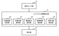
- the data collection unit 1 includes, for example, a position estimation unit 11, a context information detection unit 12, a target ID estimation unit 13, and a matching unit 14, all of which are functional units.
- the positioning sensor unit 10 collects data from sensors connected to the positioning assistance system 100 by wire or wirelessly.
- the sensor data includes, for example, position data obtained from a GPS (Global Positioning System), a wireless LAN (Local Area Network) device, a beacon, etc., image data captured by a camera installed in the facility, and acceleration data and angular velocity data measured by a built-in sensor in a terminal (e.g., a smartphone, etc.) attached to or carried by the target.
- the position estimation unit 11 estimates position information using various data collected by the positioning sensor unit 10.
- the position estimation unit 11 estimates the position of the target by combining multiple sensor data, thereby compensating for situations in which each type of data is difficult to observe, and enabling highly accurate position estimation that is not affected by the environment.
- the position estimation unit 11 uses, for example, a method of estimating a position based on the reception strength and transmission/reception speed of radio waves, a method of detecting an object from a camera image and acquiring the coordinates of the detected object, a method of identifying a position by comparing a camera image with an environmental image measured in advance, and PDR (Pedestrian Dead Reckoning) that accumulates acceleration and angular velocity data and converts it into relative coordinates.
- PDR pedestrian Dead Reckoning
- the position estimation unit 11 may calculate a confidence value for the position information from the variance in the estimated position, and store the position information obtained from multiple types of positioning methods and sensor data in the observation DB 2 without integrating them.
- a function is defined in advance that outputs a certainty value regarding the location information when an index (e.g., variance, etc.) indicating the variance of the estimated location is input for the same target at the same time (which may be a time period within a predetermined time difference), and the larger the variance of the estimated location, the smaller the certainty value becomes.
- a coefficient e.g., the coefficient for an image is larger than the coefficient for an acceleration sensor and PDR
- the certainty may be calculated by multiplying the value output from the function by the coefficient.
- the context information detection unit 12 detects context from the sensor data acquired by the positioning sensor unit 10. Examples of context include the movement, stillness, and transformation of an object, changes in the environment around the object, and the object passing by or accompanying a landmark or another object.
- the target is an agent (a person, robot, or other entity capable of autonomous behavior)
- the context related to the target may include actions such as work, service usage, and conversation by the agent. Details of the method for detecting context information will be described later with reference to FIG. 2.
- the target ID estimation unit 13 estimates which target ID is linked to the estimated location information and detected context information.
- the target ID is information that uniquely identifies the target, and if the target ID is linked to a terminal attached to or carried by the target, the target ID estimation unit 13 links the target ID to information obtained from a sensor built into the terminal (for example, a built-in sensor of the terminal such as a radio wave or acceleration sensor).
- the target ID estimation unit 13 identifies the target contained in the image, for example, by a method such as image analysis, and links the target ID of the identified target. Note that, for example, the correspondence between the type of sensor that measured the data from which the location information or context information was generated and the method of linking the target ID is determined in advance.
- the matching unit 14 links the information output by the position estimation unit 11, the context information detection unit 12, and the target ID estimation unit 13, and stores the information in the observation DB 2.
- observation DB2 location information and context information collected by the data collection unit 1 are stored.
- location information obtained by multiple positioning methods for the same object may be stored in the observation DB2.
- the observation DB2 may store information on the degree of certainty of location information. Details of the data stored in the observation DB2 will be described later with reference to FIG. 3.
- the target designation information receiving unit 3 receives information designating the target and time for which location information is to be registered in the record DB 7, for example through input from a user.
- the observation information extracting unit 4 extracts data relating to the target and time designated by the target designation information receiving unit 3 from the observation DB 2.
- the observation information extracting unit 4 may extract not only the designated time, but also a time series of the location information of the designated target in a time window of a predetermined length that includes the designated time (for example, starting from the designated time).
- the observation information extracting unit 4 may also extract data other than the designated target (records relating to targets other than the designated target, and records in which the target is not specified) from the observation DB 2 at the designated time or in a time window of a predetermined length that includes the designated time.
- the candidate position estimation unit 5 estimates candidate positions of the specified target around the specified time from the information extracted by the observation information extraction unit 4.
- the user dialogue unit 6 interactively determines the location information to be registered with the user. Details of the candidate position estimation unit 5 and the user dialogue unit 6 will be described later using Figures 4 and 6, respectively. In particular, the processing by the user dialogue unit 6 plays an important role in preventing errors in registering location information due to user forgetfulness.
- the record DB 7 holds the location information of the target determined by the user dialogue unit 6.
- FIG. 1B is a block diagram showing an example of the hardware configuration of a computer that constitutes the positioning assistance system 100.
- the positioning assistance system 100 is composed of a computer 1000 having, for example, a CPU (Central Processing Unit) 1001, a memory 1002, an auxiliary storage device 1003, an input device 1004, a display device 1005, and a communication device 1006.
- a CPU Central Processing Unit
- the CPU 1001 is an example of a processor, and executes programs stored in the memory 1002.
- the memory 1002 includes a ROM (Read Only Memory), which is a non-volatile storage element, and a RAM (Random Access Memory), which is a volatile storage element.
- the ROM stores immutable programs (e.g., BIOS (Basic Input/Output System)).
- BIOS Basic Input/Output System
- the RAM is a high-speed, volatile storage element such as a DRAM (Dynamic Random Access Memory), and temporarily stores programs executed by the CPU 1001 and data used when the programs are executed.
- the auxiliary storage device 1003 is, for example, a large-capacity, non-volatile storage device such as a magnetic storage device (HDD (Hard Disk Drive)) or a flash memory (SSD (Solid State Drive)), and stores the programs executed by the CPU 1001 and data used when the programs are executed. In other words, the programs are read from the auxiliary storage device 1003, loaded into the memory 1002, and executed by the CPU 1001.
- HDD Hard Disk Drive
- SSD Solid State Drive
- the input device 1004 is a device, such as a keyboard or mouse, that receives input from an operator.
- the display device 1005 is a device, such as a display device or printer, that outputs the results of program execution in a format that can be viewed by the operator.
- the communication device 1006 is a network interface device that controls communication with other devices according to a specific protocol.
- the communication device 1006 also includes a serial interface such as a Universal Serial Bus (USB).
- USB Universal Serial Bus
- a part or all of the programs executed by the CPU 1001 may be provided to the computer 1000 via a network from a removable medium (CD-ROM, flash memory, etc.) that is a non-transitory storage medium, or from an external computer equipped with a non-transitory storage device, and may be stored in a non-volatile auxiliary storage device 1003 that is a non-transitory storage medium.
- the computer 1000 may have an interface for reading data from removable media.
- the positioning assistance system 100 is a computer system configured on a single physical computer 1000, or on multiple logically or physically configured computers 1000, and may operate in separate threads on the same computer 1000, or may operate on a virtual computer constructed on multiple physical computer resources.
- the CPU 1001 includes, for example, each functional unit of the positioning assistance system 100.
- the CPU 1001 functions as a data collection unit 1 by operating according to a data collection program loaded into the memory 1002, and functions as a target designation information receiving unit 3 by operating according to a target designation information receiving program loaded into the memory 1002.
- the relationships between programs and functional units are similar for the other functional units of the positioning assistance system 100.
- the functions of the functional units of the positioning assistance system 100 may be realized by hardware such as an ASIC (Application Specific Integrated Circuit) or an FPGA (Field-Programmable Gate Array).
- ASIC Application Specific Integrated Circuit
- FPGA Field-Programmable Gate Array
- the auxiliary storage device 1003 holds the observation DB 2 and the record DB 7. Note that some or all of the information stored in the auxiliary storage device 1003 may be stored in the memory 1002, or in an external DB connected to the positioning assistance system 100.
- FIG. 2 is a block diagram showing an example of the configuration of the context information detection unit 12.
- the context information detection unit 12 detects the occurrence of a context at the current time by monitoring data changes indicated by sequence data from a specified sensor within a time window of a specified length that ends at the current time, among the sensor data input from the positioning sensor unit 10.
- the context information detection unit 12 includes, for example, a target movement determination unit 120, a target transformation detection unit 121, an environmental change detection unit 122, an environmental solidarity detection unit 123, and a target behavior detection unit 124, all of which are functional units that detect the occurrence of a context.
- the object movement determination unit 120 determines the movement state of the object at each time included in the time window based on the sensor data, for example, by monitoring the transition of the object's position in the time window.
- the movement state of the object is either moving or stopped.
- the object movement determination unit 120 determines that the position of the object changes continuously at a speed equal to or greater than a certain speed within the time window based on data measured by a specified sensor indicating position or data measured by a specified sensor indicating speed or acceleration, it detects the movement of the object at the current time as a context.
- the object movement determination unit 120 determines that the average movement speed of the object within the time window is equal to or greater than a predetermined threshold based on data measured by a predetermined sensor indicating position or data measured by a predetermined sensor indicating speed or acceleration, or when it determines that the total movement amount of the object within the time window is equal to or greater than a predetermined threshold, it detects the movement of the object at the current time as a context.
- the target movement determination unit 120 may perform additional processing to reduce the effects of noise by excluding the sensor data from the detection target for movement determination if the speed, acceleration, or jerk is equal to or greater than a threshold value, or by applying a Kalman filter to the series data in the time window.
- the object transformation detection unit 121 detects the transformation of the object at the current time as a context, for example, by monitoring changes in the appearance of the object in a time window. Specifically, for example, the object transformation detection unit 121 detects the transformation of the object at the current time by comparing the amount of change in pixel units within the camera image area in which the object was photographed. Also, for example, in cases where the appearance of the object before and after the transformation can be predicted in advance, an object detector that detects the object before and after the transformation may be prepared in advance, and the object transformation detection unit 121 may detect the transformation of the object at the current time by applying the object detector to the image data.
- the environmental change detection unit 122 detects environmental changes at the current time as context, for example, by monitoring changes in the environment other than the target during a time window. Specifically, for example, the environmental change detection unit 122 detects environmental changes at the current time (within a specified distance from the target) by comparing the amount of change in pixel units within the camera image area in which the target is photographed.
- an object detector that detects the environment before and after the change may be prepared in advance, and the environmental change detection unit 122 may detect changes in the environment at the current time by applying the object detector to the camera image.
- the environmental change detection unit 122 may, for example, detect a specific behavior of the agent output by applying image data to a specific behavior recognition model as a change in the environment at the current time, and detect the change in the environment as a context.
- the environmental solidarity detection unit 123 detects, for example, a change in at least one of an object and an environmental object (an object different from the object) that occurs during a time window when the object and the environmental object are involved (hereinafter referred to as environmental solidarity) as a context.
- object and an environmental object an object different from the object
- environmental solidarity a change in at least one of an object and an environmental object (an object different from the object) that occurs during a time window when the object and the environmental object are involved.
- environmental solidarity Objects, landmarks, agents, etc. in the environment are all examples of environmental objects.
- results of actions that link an object and an environmental object are all examples of environmental solidarity.
- the environmental solidarity detection unit 123 detects environmental solidarity using video analysis of camera images, for example, by comparing the position information of the target and environmental objects to detect passing by or following an object.
- the target behavior detection unit 124 determines that the target, which is an agent, has performed a predetermined characteristic behavior within a time window, it detects the characteristic behavior as a context.
- the target performing a predetermined task, the target using a predetermined service related to the task, and behavior such as conversation by the target are all examples of characteristic behavior by the target.
- the target behavior detection unit 124 detects that the target has performed a task by using time series analysis of camera images and posture estimation sensors, detects that the target has used a service by searching sensor data that indicates the service usage history, and detects conversations by the target by transcribing and analyzing voice data.
- FIG. 3 is a diagram showing an example of the data structure of data stored in the observation DB2.
- the observation DB2 includes a location information table T21 that includes target location information, and a context information table T22 that includes context information.
- the location information table T21 includes, for example, a location information ID, a positioning time, location information such as coordinates, a target ID, a positioning method, and a confidence value related to the location information.
- the location information ID is an ID that identifies a record in the location information table T21.
- the positioning time indicates the time when the sensor data from which the location was calculated was measured.
- the location information indicates the location estimated by the location estimation unit 11, and indicates, for example, coordinate values obtained directly from a sensor such as a GPS, or coordinate values obtained by applying PDR to an acceleration sensor, etc.
- the target ID is assigned to the location information by the target ID estimation unit 13.
- the positioning method indicates the type of sensor. Note that if the sensor value does not indicate the location itself, such as when coordinates are obtained by applying PDR to an acceleration sensor, the name of an algorithm such as PDR may also be stored as the positioning method.
- the certainty value for location information is an index showing the possibility that the target ID was at the location at the time of positioning, and is calculated by the method described above. Note that if it is difficult to calculate an accurate certainty, such as when the source of location information does not have rich information, certainty values may not be assigned to some or all of the records in the location information table T21.
- the context information table T22 includes, for example, a context ID, a time when the context occurred, a location where the context occurred, a context type, a target ID involved in the context, and a confidence value regarding the context occurrence.
- the context ID is an ID that identifies a record in the context information table T22.
- the context occurrence time indicates the time when the context detected by the context information detection unit 12 occurred.
- the context occurrence position indicates the position where the context detected by the context information detection unit 12 occurred.
- Each functional unit included in the context information detection unit 12 extracts or calculates the position of an object from the sensor data used when the context was detected, and determines the extracted or calculated position of the object as the context occurrence position.
- the context type indicates the type of context detected by the context information detection unit 12, and specifically includes, for example, the aforementioned target movement, target transformation, environmental change, environmental solidarity, and target behavior.
- the certainty value regarding context occurrence is an index that indicates the possibility that a context of the context type involving the target ID occurred at the context occurrence time at the context occurrence location.
- Each functional unit of the context information detection unit 12 calculates the certainty value regarding context occurrence by, for example, performing a process similar to the calculation of the certainty value regarding location information for the context occurrence location. Note that if it is difficult to calculate an accurate certainty, such as when the information source for context detection does not have rich information, certainty values may not be assigned to some or all of the records in the context information table T22.
- FIG. 4 is a block diagram showing an example of the configuration of the candidate position estimation unit 5.
- the candidate position estimation unit 5 estimates a candidate position of the target from the observation information extracted by the observation information extraction unit 4, corrects it based on the route and context information, selects information to be presented to the user, and outputs it to the user dialogue unit 6.
- the candidate position estimation unit 5 has a function of receiving feedback from the user dialogue unit 6 and re-estimating the candidate position.
- the candidate position extraction unit 51 may include the position information of the other target in the candidate position of the specified target.
- the route estimation unit 52 estimates the movement route of the specified object within a time window of a predetermined length that includes the time corresponding to each extracted candidate location. At this time, in order to provide consistency in the route information, the route estimation unit 52 may correct the section included in the route.
- the route estimation unit 52 performs a complementation process based on a specified algorithm using information from the non-missing section. Also, if there is a lot of noise in the sensor data, such as a large variation in values, or if the confidence value of the positioned surrounding route is low (for example, below a specified value), the route estimation unit 52 may correct the route using a Kalman filter or bilinear complementation. Also, an example of correcting positioning information obtained by PDR with positioning information obtained by camera images will be described later, and in this way, a correction algorithm may be predetermined for each positioning method.
- the route-based evaluation value estimation unit 53 calculates an evaluation value for each route estimated by the route estimation unit 52. For example, the route-based evaluation value decreases as the amount of correction from the route obtained from the original positioning data increases.
- the degree of certainty of the positions included in the route may be further taken into consideration in calculating the route-based evaluation value, and in this case, the lower the degree of certainty, the smaller the route-based evaluation value. Details of the route-based evaluation value calculation process will be described later with reference to FIG. 5.
- the related context estimation unit 54 estimates, for each extracted candidate position, a context related to the specified target within a specified time window as a related context for the candidate position of the target. Specifically, for example, the related context estimation unit 54 estimates, as a related context, a context indicated by a record including the target ID of the specified target in the context information table T22 included in the extracted observation information, where the context occurrence time is within a specified time window and/or the occurrence position is within a specified distance.
- the related context estimation unit 54 also estimates, as related contexts of the target, those contexts whose context occurrence position is within a predetermined distance from the candidate position of the specified target or whose context occurrence time is within a predetermined time difference from the time corresponding to the candidate position, even though the target ID of the specified target in the context information table T22 included in the extracted observation information is not included.
- the context-based evaluation value estimation unit 55 calculates the probability that the specified target was involved in the related context estimated by the related context estimation unit 54 as a context-based evaluation value.
- the context-based evaluation value estimation unit 55 calculates the probability that the target will be detected in image processing of the image in which the related context was detected as the context-based evaluation value.
- the context-based evaluation value estimation unit 55 may calculate, from the position information and positioning time of the target before and after the context occurrence (for example, from a predetermined time before to a predetermined time after the context occurrence time), as well as the context occurrence position and context occurrence time, the probability that the target can reach the context occurrence position from the position before the context occurrence, or the probability that the target can reach the position after the context occurrence from the context occurrence position, as the context-based evaluation value.
- the presentation information selection unit 56 receives the outputs of the route estimation unit 52, the route-based evaluation value estimation unit 53, the related context estimation unit 54, and the context-based evaluation value estimation unit 55, selects and prioritizes information to be presented to the user, and displays it, for example, on the display device 1005.
- the presentation information selection unit 56 outputs, for example, candidate locations, routes corresponding to the candidate locations, and related context information, prioritizing them based on the route-based evaluation value and the context-based evaluation value.
- FIG. 5 is an explanatory diagram showing an example of the route correction process and the route-based evaluation value calculation process.
- the positioning information from the PDR is corrected using the positioning information from the camera image.
- the relative position from the measurement start point is calculated by integrating the acceleration and angular velocity measured by the sensor mounted on the mobile terminal.
- the route estimation unit 52 detects a section of the image estimated route 533 that coincides with the PDR estimated route 531 in time or space.
- the PDR estimated route 531 and the image estimated route 533 both obtain sections for the same time period (from "9:10" to "9:12"), so the route estimation unit 52 corrects the section of the PDR estimated route 531 from “9:10” to "9:12" to match the section of the image estimated route 533 from "9:10" to "9:12".
- the route estimation unit 52 calculates the section before "9:10” by, for example, drawing a straight line between the start point and the corrected position at "9:10", and calculates the section after "9:12” assuming that movement after "9:12” indicated by the PDR estimated route 531 occurred from the corrected position at "9:12", thereby calculating the corrected PDR estimated route 534. In this way, the route estimation unit 52 resets the accumulated error by updating the position information as appropriate.
- the path-based evaluation value estimation unit 53 calculates, for example, the total amount of change in position at each time between the PDR estimated path 531 and the corrected PDR estimated path 534 as the path-based evaluation value.
- the path-based evaluation value estimation unit 53 may also calculate, as the path-based evaluation value, the amount of change between the PDR parameters when the PDR estimated path 531 is obtained and the parameters for obtaining the corrected PDR estimated path 534 using the PDR.
- FIG. 6 is a block diagram showing an example of the configuration of the user dialogue unit 6.
- the user dialogue unit 6 includes, for example, an information display unit 61, a position specification receiving unit 62, a requested information selection unit 63, and an additional information receiving unit 64, all of which are functional units.
- the information display unit 61 displays the information output from the candidate position estimation unit 5 on a GUI (Graphical User Interface).
- the position specification receiving unit 62 receives input of the position information to be registered or an input requesting re-estimation of the candidate position from the user via the input device 1004, and outputs an instruction to the requested information selection unit 63 to register the position information in the record DB 7 or to re-estimate the candidate position according to the user input result.
- the user selects the location information to be registered from the candidate position. Also, for example, if the user determines that the candidate position displayed by the information display unit 61 does not have correct location information, the user manually inputs location information or instructs re-estimation of the candidate position.
- the requested information selection unit 63 When the requested information selection unit 63 receives an instruction to re-estimate the candidate position, it determines the information (request information) to be input by the user.
- the information display unit 61 displays the requested information on the GUI.
- the additional information receiving unit 64 accepts input of additional information corresponding to the requested information from the user via the input device 1004, and outputs the input additional information to the candidate position estimation unit 5.
- the candidate position estimation unit 5 re-estimates the candidate position according to the input additional information.
- the information display unit 61 includes, for example, a map display unit 611, a candidate location display unit 612, a candidate route display unit 613, a related context display unit 614, and a requested information display unit 615, all of which are functional units.
- the map display unit 611 displays a map of the facility through which the subject has moved. Note that the map data is stored in advance in the auxiliary storage device 1003, for example.
- the candidate position display unit 612 displays the candidate positions estimated by the candidate position estimation unit 5.
- the candidate route display unit 613 displays the routes corresponding to the candidate positions.
- the related context display unit 614 displays the related context estimated by the related context estimation unit 54.
- the requested information display unit 615 displays requested information. Details of the display contents of the candidate position display unit 612, candidate route display unit 613, and related context display unit 614 will be described later with reference to Figures 7A to 9C.
- the user dialogue unit 6 executes user assistance processing and machine assistance processing.
- the user assistance processing includes processing executed by the map display unit 611, candidate location display unit 612, candidate route display unit 613, related context display unit 614, and location specification receiving unit 62.
- the user assistance processing is processing in which the machine (display unit) visually assists the user by displaying a GUI and using an input screen, with the aim of reducing the user's misremembering, sensory discrepancies, and forgetting about location information, and of reminding the user of the target situation at the time.
- the machine-assisted processing includes processing by the requested information selection unit 63, the requested information display unit 615, and the additional information receiving unit 64.
- the machine-assisted processing is a process that automatically selects requested information to support an estimation with a low rating, with the aim of reducing errors in machine-based position estimation, and assists the machine (estimation unit) by having the user input additional information corresponding to the requested information.
- the user and the machine assist each other, and the user is exposed to information about the subject at the time, which can encourage the user to recall the correct situation. Details of the processing by the user dialogue unit 6 will be described later with reference to FIG. 10.
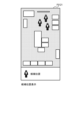
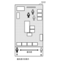
- FIGS. 7A and 7B are diagrams showing example screen configurations of a GUI realized by the candidate position display unit 612.
- Display screen F6121 in FIG. 7A and display screen F6122 in FIG. 7B both display an electronic map viewed from above by the map display unit 611, and display a human-shaped icon indicating the candidate position of the specified target.
- the candidate position display unit 612 displays estimated position information on the electronic map, allowing the user to intuitively recognize which location on the actual site the candidate position represents.
- the human-shaped icons are buttons, and the user can select an icon to select the position information linked to that icon, and the selected position information is registered in the record DB7 as the position of the target.
- All the human icons on the display screen F6121 are displayed in the same manner (lines of the same thickness).
- the display is differentiated by the thickness of the line of the human icon (the thicker the line, the higher the priority).
- Priority may be expressed in other ways, such as the shade of the color of the icon, the transparency of the icon, the size of the icon, or by displaying a priority value together with the icon.
- the priority on the display screen F6122 is calculated by, for example, a weighted sum of the route-based evaluation value and the context-based evaluation value using a predetermined weight.
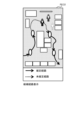
- FIGS. 8A, 8B, and 8C are diagrams showing example screen configurations of a GUI realized by the candidate route display unit 613.
- display screen F6131 in FIG. 8A, display screen F6132 in FIG. 8B, and display screen F6133 in FIG. 8C all display an electronic map viewed from above by the map display unit 611, and display human-shaped icons indicating candidate locations and priorities.
- display screens F6131 to F6133 the route that is estimated to have been taken by the specified target if it had passed through the candidate locations is shown by solid and dotted arrows.
- the candidate route display unit 613 thus shows virtual travel routes corresponding to each candidate location, allowing the user to select a location candidate based on their memory of the time. This makes it possible to prevent erroneous location registration due to a user's faulty memory or misperception.
- the candidate route display unit 613 may assist the user in making a selection by visualizing the route-based evaluation value of each route on the GUI.
- routes with high route-based evaluation values are drawn with solid lines and routes with low route-based evaluation values are drawn with dotted lines based on a predetermined threshold value, making it possible to distinguish between the routes.
- routes with high route-based evaluation values are displayed as confirmed routes, and routes with low route-based evaluation values are displayed as unconfirmed routes, thereby preventing the user from inadvertently selecting a route with a low degree of certainty.
- routes corresponding to the candidate positions corresponding to the icon selected by the user are displayed.
- the route-based evaluation value is visualized by continuously changing the state of the line of the arrow indicating the route (for example, represented by thickness, color, and/or shading. In the example of FIG. 8B, the thicker the dotted line, the higher the route-based evaluation value).
- This visualizes the criteria that the user uses when selecting a candidate position within an undetermined route section, and functions as an aid when the user selects a candidate position and when the user manually fine-tunes the candidate position.
- the route and route-based evaluation value corresponding to the candidate position indicated by each icon are displayed.
- Display screen F6133 visualizes the distribution of route-based evaluation values of routes corresponding to the estimated position. This allows the user to intuitively know in which area of the map the position to be registered will have a high route-based evaluation value, and the distribution functions as an aid when the user manually fine-tunes the candidate position. Note that the candidate route display unit 613 calculates the distribution by, for example, calculating the route-based evaluation value when the candidate position of the specified target at the specified time is shifted.
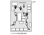
- FIGS. 9A, 9B, and 9C are diagrams showing example screen configurations of a GUI realized by the related context display unit 614.
- display screen F6141 in FIG. 9A, display screen F6142 in FIG. 9B, and display screen F6143 in FIG. 9C all display an electronic map viewed from above by the map display unit 611, and display human-shaped icons indicating candidate locations and priorities.
- all of display screens F6141 to F6143 show, with solid and dotted arrows, the route that is estimated to have been taken by the specified target if it had passed through the candidate locations.
- the context that occurred at the specified time (and a time window of a predetermined length that includes that time) is displayed with a pin-shaped icon at a position that indicates the context occurrence position.
- the related context corresponding to the selected candidate position or each of the displayed candidate positions on the display screens F6141 to F6143 may be displayed with a pin-shaped icon, or all contexts that occurred at context occurrence positions within a predetermined distance of the selected candidate position or each of the displayed candidate positions may be displayed with a pin-shaped icon.
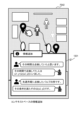
- the pin-shaped icons are buttons, and when a pin-shaped icon is selected on the display screen F6142, details of the context associated with that icon are displayed as shown on the display screen F6142. As details of the context, for example, the time of occurrence of the context (the date in FIG. 8B and the display of "2 minutes ago"), the context type (the event in FIG. 8B), and the confidence level regarding the context are displayed.
- the related context display unit 614 may estimate the relationship between the candidate location and each context, and may explicitly display it as in display screen F6143.
- the related context display unit 614 picks up contexts linked to the specified target ID that occurred within a specified distance and within a specified time from the selected candidate location, and presents the relationship to the user in a text format as shown in display screen F6143 (for example, as shown in FIG. 9C, the timeline of the contexts is displayed in text order in the order of occurrence of the picked contexts).
- the presentation method is not limited to text, and other formats such as tables, flows, and graphs may also be used.
- FIG. 10 is a flowchart showing an example of an interactive registration process of location information by the candidate location estimation unit 5 and the user dialogue unit 6.
- step S7001 the candidate position estimation unit 5 estimates the candidate position of the specified target, the route corresponding to the candidate position, and related context information using the method described using Figures 4 and 5, etc.
- step S7002 the candidate location display unit 612, the candidate route display unit 613, and the related context display unit 614 display the information estimated in step S7001 on the display device 1005. That is, for example, at least one of the display screens F6121 to F6122, at least one of the display screens F6131 to F6133, and at least one of the display screens F6141 to F6143 are displayed on the display device 1005.
- step S7003 the position specification receiving unit 62 receives, via input by the user to the input device 1004, information indicating whether or not the correct position is among the candidate positions presented in step S7002, and, if a correct position is present, information indicating the correct candidate position (selected by the user from the presented candidate positions). Note that, although not shown in Figures 7A to 9C, for example, input areas for receiving input of this information are displayed on each display screen.
- step S7004 the position specification receiving unit 62 registers the position information (the combination of the specified target, position, and time) of the candidate position selected by the user in step S7003 in the recording DB7, and ends the interactive registration process.
- step S7005 the position specification receiving unit 62 receives information indicating whether the user manually inputs position information via an input by the user to the input device 1004. Note that although not shown in Figures 7A to 9C, for example, an input area for receiving input of the information is displayed on each display screen.
- step S7006 the location specification receiving unit 62 receives the input of location information via an input by the user to the input device 1004. Specifically, for example, the user inputs a location via the input device 1004 by selecting a specific location on a map displayed on the GUI or by inputting coordinate values. Note that in step S7006, the location specification receiving unit 62 may further receive user input of a target and time in addition to a location.
- step S7007 the location specification receiving unit 62 registers the location information, including the location input by the user in step S7006, in the recording DB 7, and ends the interactive registration process.
- step S7008 the request information selecting unit 63 generates request information to estimate accurate candidate locations.
- the request information selection unit 63 generates, as request information, a question asking whether the context displayed on the display screens F6141 to F6143 has occurred in relation to the specified target, a question asking whether a context not displayed on the display screens F6141 to F6143, whose context occurrence position is within a predetermined distance from the candidate position (or candidate route), has occurred in relation to the specified target, etc.
- step S7009 the request information selection unit 63 displays the request information generated in step S7008 on the display device 1005, and accepts input of additional information for the request information via input by the user to the input device 1004.
- step S7010 the request information selection unit 63 inputs the additional information acquired in step S7008 to the candidate position estimation unit 5, and returns to step S7001 to continue candidate position estimation and user interaction processing.
- the candidate position estimation unit 5 sets the position at which the context occurred as a candidate position and regenerates a route and related context corresponding to the candidate position. Also, for example, if the additional information includes information indicating that a certain context has not occurred in relation to the specified target, the candidate position estimation unit 5 deletes the candidate position corresponding to the context (for example, a candidate position included within a specified distance from the position at which the context occurred) and the route and related context corresponding to the candidate position.
- Example 2 a conditioning process based on the evaluation value of the estimation result is further added to the interactive registration process of location information by the candidate location estimation unit 5 and the user dialogue unit 6. Specifically, if the evaluation value of the estimation result is low, the process does not proceed to step S7004 where the user registers the candidate location in the user dialogue unit 6, but proceeds directly to step S7008 where request information is generated. This prevents the user from performing registration work based on uncertain estimation results, making it possible to eliminate user mistakes and unnecessary dialogue during registration.
- FIG. 11 is a flowchart showing an example of an interactive registration process of location information by the candidate location estimation unit 5 and the user dialogue unit 6.
- step S7011 the request information selection unit 63 determines whether the evaluation value of the candidate estimated in step S7001 is sufficiently high. Specifically, for example, the request information selection unit 63 determines whether the route-based evaluation value and the context-based evaluation value corresponding to the candidate position output by the candidate position estimation unit 5 exceed a predetermined threshold value.
- step S7011 determines in step S7011 that the evaluation value is sufficiently high, the process transitions to step S7002. On the other hand, if the request information selection unit 63 determines in step S7011 that the evaluation value is not sufficiently high, the process transitions to step S7008.
- Example 3 the freedom of interaction between the user and the machine is increased by executing a process of providing additional information to the candidate position estimation unit 5 based on a user's suggestion.
- the request information selection unit 63 selects request information based on the observation information, and the candidate position estimation unit 5 re-estimates the candidate position using the additional information input for the request information. While the method in Examples 1 and 2 has the effect of reducing the burden of operation and recall on the user's side, there is a possibility that the evaluation value of the candidate information may not be increased sufficiently with only the information possessed by the positioning assistance system 100.
- the user dialogue unit 6 accepts input of new information held by the user, thereby efficiently increasing the evaluation value.
- FIG. 12 is a block diagram showing an example of the configuration of the user dialogue unit 6.
- the user dialogue unit 6 further includes a user-suggested information receiving unit 65, which is a functional unit
- the information display unit 61 further includes an information addition column display unit 616, which is a functional unit.
- the information addition field display unit 616 displays an input field on the GUI for the user to add information as desired.
- Information in the form of text or media information, for example, can be input into the input field.
- the information addition field display unit 616 outputs the suggested information input into the input field to the user suggested information receiving unit 65.
- the user-suggested information receiving unit 65 outputs the suggested information input from the information addition field display unit 616 to the candidate position estimation unit 5.
- the candidate position estimation unit 5 uses the suggested information to estimate the next candidate.
- the user-suggested information receiving unit 65 converts the suggested information input from the information addition field display unit 616 into any one of the following formats: location information, route information, and/or related context information.
- FIG. 13A, 13B, and 13C are diagrams showing an example of a GUI screen configuration realized by the information addition column display unit 616.
- a speech bubble icon is displayed in the display screen F641 in FIG. 13A.
- a process of suggesting addition of information by the user is started, and the screen transitions to, for example, the display screen F642 in FIG. 13B or the display screen F643 in FIG. 13C.
- Display screen F642 displays a box 1301 for interactively adding information through text.
- the text written in the speech bubble of the human icon is suggested information entered by the user
- the text written in the speech bubble of the robot icon is text indicating a candidate that has been re-estimated by candidate position estimation unit 5 based on the suggested information.
- the candidate position estimation unit 5 extracts from the context information table T22 the context occurrence position of a context whose context occurrence time is within a predetermined time from the relevant time and whose context type includes "inspection,” and outputs a sentence indicating the context occurrence position, "The people who were inspecting at that time were at (x1, y1) and (x2, y2).".
- the candidate position estimation unit 5 extracts from the context information table T22 the context occurrence position of the context whose context occurrence time is "last Monday” and whose context type includes “inspection” and “valve,” and outputs "The condition is satisfied by (x2, y2),” which is a sentence indicating the position between (x1, y1) and (x2, y2) that corresponds to the extracted context occurrence position.
- Display screen F643 displays box 1302 for interactively adding information using text and media information.
- the text and media written in the speech bubble of the human icon are suggested information entered by the user, and the text written in the speech bubble of the robot icon is text indicating a candidate that has been re-estimated by candidate position estimation unit 5 based on the suggested information.
- the candidate position estimation unit 5 performs a search using the image and the word "robot arm” as search keys, and outputs the sentence "This robot arm is located at (x3, y3)," which indicates the installation position of the robot arm.
- the positioning assistance system 100 holds a database in which images of various pieces of equipment and information indicating the equipment names and installation locations are stored, and searches are performed on the database.
- the dialogue in Figs. 13B and 13C is realized by interactive AI (Artificial Intelligence).
- the present invention is not limited to the above-described embodiments, but includes various modified examples.
- the above-described embodiments have been described in detail to clearly explain the present invention, and are not necessarily limited to those having all of the configurations described. It is also possible to replace part of the configuration of one embodiment with the configuration of another embodiment, and it is also possible to add the configuration of another embodiment to the configuration of one embodiment. It is also possible to add, delete, or replace part of the configuration of each embodiment with other configurations.
- the above-mentioned configurations, functions, processing units, processing means, etc. may be realized in hardware, in part or in whole, for example by designing them as integrated circuits. Furthermore, the above-mentioned configurations, functions, etc. may be realized in software, by a processor interpreting and executing a program that realizes each function. Information on the programs, tables, files, etc. that realize each function can be stored in a memory, a recording device such as a hard disk or SSD (Solid State Drive), or a recording medium such as an IC card, SD card, or DVD.
- a recording device such as a hard disk or SSD (Solid State Drive)
- a recording medium such as an IC card, SD card, or DVD.
- control lines and information lines shown are those considered necessary for the explanation, and do not necessarily show all control lines and information lines on the product. In reality, it can be assumed that almost all components are interconnected.
Landscapes
- Engineering & Computer Science (AREA)
- Radar, Positioning & Navigation (AREA)
- Remote Sensing (AREA)
- Physics & Mathematics (AREA)
- General Physics & Mathematics (AREA)
- Automation & Control Theory (AREA)
- Navigation (AREA)
- Traffic Control Systems (AREA)
Abstract
情報処理システムは、対象の候補位置と、当該対象が当該候補位置にいた時刻と、を示す位置情報と、発生したコンテキストと、コンテキスト発生時刻と、コンテキストに関わった対象と、を示すコンテキスト情報と、を保持し、指定された対象及び時刻の候補位置を位置情報から取得し、当該指定された時刻及び対象に対応するコンテキストをコンテキスト情報から取得し、当該取得した候補位置と、当該取得したコンテキストと、を表示し、当該表示した候補位置から登録対象の位置の選択を受け付けて登録する。
Description
本出願は、2023年6月21日に出願された日本特許出願第2023-101744号の優先権を主張し、その内容を参照することにより、本出願に取り込む。
本発明は、情報処理システム及び情報処理方法に関する。
個人所有の携帯端末の増加に伴い、近年は端末の測位データを用いた位置情報サービスが広く利用されている。特に外出先でのナビゲーションや地理データに紐づいた情報共有および検索など、ユーザの日常的な行動を決定する上で欠かせないツールとなっている。
これらのサービスは現場での業務利用を目的に使われる場合もあり、その際サービスの品質として重要視されるのは測位データの正確性である。そのため、屋内外問わず任意の場所で正確に測位し、情報を登録できるシステムが求められている。近年はGPS(Global Positioning System)やビーコン、加速度センサなどのセンサデータや、ユーザによる入力情報を基に測位データを補正する手法が提案されている。
本技術分野の背景技術として、特開2008-242408号公報(特許文献1)がある。この公報には、「サーバは、複数の地点に関する位置情報および名称を示す地点データを予め記憶し、電子地図においてユーザによって入力された位置を示す位置データを端末装置から受信し、受信した位置データが示す位置から所定の距離範囲内の位置を示す位置情報に対応する地点データを抽出し、所定数の候補地点データとして端末装置に送信し、ユーザによって選択された候補地点データを、選択データとして端末装置から受信し、受信した選択データに対応する地点データに基づいて、位置データを地点データの位置情報に補正して端末装置に送信する。」と記載されている(要約参照)。
自動測位のための情報源を増やすだけでは最終的な測位ミスのリスクを取り除くことは難しい。業務利用が目的の場合、測位ミスが後の業務に大きく影響を及ぼす可能性があるため、より頑健なシステムが求められる。特許文献1に記載の技術では、位置情報を登録する際にユーザに最終的な判断を委任することで測位ミスのリスク低減を図っている。
ここで注意するべきは、ユーザも測位システム同様にミスをするリスクがあることである。ユーザが記憶している情報も絶対ではなく、記憶違い、位置感覚のズレ、及び忘却等により情報が正確でない可能性が十分にある。特許文献1に記載の技術では、ユーザが当時の地理的な状況を忘却してしまった場合に正確な位置情報を登録することができない。
そこで本発明の一態様は、ユーザが記憶している情報が不十分であっても当時の状況を想起させやすくし、ひいては登録される位置情報の精度を向上させる。
上記課題を解決するために、本発明の一態様は以下の構成を採用する。情報処理システムは、プロセッサとメモリと表示装置とを備え、前記メモリは、対象の候補位置と、当該対象が当該候補位置にいた時刻と、を示す位置情報と、発生した所定の事象であるコンテキストと、前記コンテキストが発生した時刻と、前記コンテキストに関わった対象と、を示すコンテキスト情報と、を保持し、前記プロセッサは、時刻と、位置を決定する対象と、の指定を受け付け、前記指定された対象の、前記指定された時刻の候補位置と、を前記位置情報から取得し、前記指定された時刻及び対象に対応するコンテキストを、関連コンテキストとして前記コンテキスト情報から取得し、前記取得した候補位置と、前記関連コンテキストと、を前記表示装置に表示し、前記表示した候補位置から登録対象の位置の選択を受け付け、前記指定された時刻及び対象と、前記登録対象の位置と、を対応付けて、前記メモリに格納する。
本発明の一態様は、ユーザが記憶している情報が不十分であっても当時の状況を想起させやすくすることができ、ひいては登録される位置情報の精度を向上させることができる。
上記した以外の課題、構成及び効果は、以下の実施形態の説明により明らかにされる。
以下、図面を参照して本発明の実施形態を説明する。以下の記載および図面は、本発明を説明するための例示であって、説明の明確化のため、適宜、省略および簡略化がなされている。なお、本実施形態は本発明を実現するための一例に過ぎず、本発明の技術的範囲を限定するものではないことに注意すべきである。特に限定しない限り、各構成要素は単数でも複数でも構わない。
以下の説明では、「テーブル」、「リスト」等の表現にて各種情報を説明することがあるが、各種情報は、これら以外のデータ構造で表現されていてもよい。データ構造に依存しないことを示すために「XXテーブル」、「XXリスト」等を「XX情報」と呼ぶことがある。識別情報について説明する際に、「識別情報」、「識別子」、「名」、「ID」、「番号」等の表現を用いるが、これらについてはお互いに置換が可能である。
実施形態を説明するための各図において、同一の構成要素には同一の名称、符号を付して、その繰り返しの説明を省略することがある。
本発明の実施例1の位置決め補助システムを図面に基づいて詳細に説明する。図1Aは、位置決め補助システムの構成例を示すブロック図である。
位置決め補助システム100は、例えば、いずれも機能部である、データ収集部1、対象指定情報受け取り部3、観測情報抽出部4、候補位置推定部5、及びユーザ対話部6を含む。また、位置決め補助システム100は、例えば、いずれも情報を格納する観測DB(DataBase)2及び記録DB7を保持する。
データ収集部1は、作業員やロボット等の追跡対象の物体又は人(以下、これらを総称して単に「対象」とも呼ぶ)の位置情報と、対象に関わる特徴的な事象を示すコンテキストに関するコンテキスト情報と、を収集する。コンテキストに該当する事象は、例えば、予め定められている。
データ収集部1は、例えば、いずれも機能部である、位置推定部11、コンテキスト情報検出部12、対象ID推定部13、及び照合部14を含む。
測位センサ部10は、位置決め補助システム100に有線又は無線で接続されたセンサからデータを収集する。センサデータは、例えば、GPS(Global Positioning System)、無線LAN(Local Area Network)機器、及びビーコン等から得られる位置データ、施設に設置されたカメラによって撮影される画像データ、並びに対象に付随又は携行される端末(例えばスマートフォン等)の内蔵センサによって計測される加速度データ及び角速度データ等を含む。
位置推定部11は、測位センサ部10が収集した各種データを用いて、位置情報を推定する。位置推定部11は、複数のセンサデータを組み合わせて対象の位置推定をすることで、各種類のデータが観測困難とする状況を補い合い、環境に左右されない高精度な位置推定を可能とする。
位置推定部11は、例えば、電波の受信強度や送受信速度に基づいて位置を推定する手法、カメラ画像から対象を検出して検出した対象の座標を取得する手法、カメラ画像と事前計測した環境画像を比較して位置を特定する手法、及び加速度及び角速度データを積算して相対的な座標に変換するPDR(Pedestrian Dead Reckoning)等を用いる。なお、例えば、センサの種別と、位置推定の方法と、の対応は予め定められている。
また、例えばPDRのように環境によって測位精度が不安定な測位手法やセンサもあるため、位置推定部11は、推定位置のばらつきから、位置情報に関する確信度値を算出し、複数種類の測位手法やセンサデータによる位置情報を統合せず観測DB2に蓄積してもよい。
例えば、同じ対象の同じ時刻(所定時間差以内の時間帯であってもよい)に推定位置のばらつきを示す指標(例えば、分散など)が入力されると位置情報に関する確信度値が出力される関数であって、推定位置のばらつきが大きいほど確信度値が小さくなるよう関数、が予め定義されている。また、測位手法(センサ種別及びアルゴリズム)ごとに係数(例えば、加速度センサ及びPDRに対する係数よりも画像に対する係数の方が大きい)が予め定められ、当該関数から出力された値に当該計数をかけることで確信度が算出されてもよい。
コンテキスト情報検出部12は、測位センサ部10が取得したセンサデータからコンテキストを検出する。対象の移動、静止、及び変容、対象の周囲の環境の変化、並びに対象がランドマークや他の対象を通過したこと及び随行したこと、等はいずれもコンテキストの一例である。
人間は対象物の客観的な位置情報よりも、主観的な体験に基づくコンテキスト情報の方が記憶及び想起しやすい。従って、ユーザが当時経験した事象や取った行動等を示すコンテキストを検出して、情報を登録する際に提示されることにより、ユーザが当時の状況を想起しやすくなる。なお、例えば、センサの種別と、コンテキスト検出方法と、の対応は予め定められている。
また、対象がエージェント(人やロボット等の自律行動が可能なもの)である場合、当該対象に関するコンテキストは、当該エージェントによる作業、サービス利用、及び会話などの行動を含んでもよい。コンテキスト情報を検出する方法の詳細は、図2を用いて後述する。
対象ID推定部13は、推定された位置情報や検出されたコンテキスト情報に、どの対象IDが紐づくかを推定する。対象IDは対象を一意に識別する情報であり、対象に付随又は携行される端末に対象IDが紐づいている場合には、対象ID推定部13は、当該端末に内蔵されたセンサ(例えば、電波や加速度センサ等の端末の内蔵センサ)から得られた情報には、当該対象IDを紐づける。
一方、施設に設置されたカメラのような環境を測定する外部のセンサから得られた情報に対しては、対象ID推定部13は、例えば、画像解析等の手法により画像に含まれる対象を特定し、当該特定した対象の対象IDを紐づける。なお、例えば、位置情報やコンテキスト情報の生成元となったデータを計測したセンサの種別と、対象IDを紐づける方法と、の対応が予め定められている。
照合部14は、位置推定部11、コンテキスト情報検出部12、及び対象ID推定部13が出力する情報を紐づけて、観測DB2に蓄積する。
観測DB2には、データ収集部1が収集した位置情報及びコンテキスト情報が蓄積される。また、計測精度が不安定なセンサから得られた位置情報もあるため、同じ対象に対して複数の測位手法による位置情報が、観測DB2に蓄積されてもよい。また、観測DB2には、位置情報の確信度情報が蓄積されてもよい。観測DB2に蓄積されるデータの詳細については図3を用いて後述する。
対象指定情報受け取り部3は、記録DB7に位置情報を登録する対象及び時刻を指定する情報を、例えばユーザからの入力によって受け取る。観測情報抽出部4は、対象指定情報受け取り部3によって指定された対象及び時刻に関するデータを観測DB2から抽出する。観測情報抽出部4は、指定された時刻だけでなく、当該時刻を含む(例えば、当該時刻から開始する)所定の長さの時間窓における、指定された対象の位置情報の時系列を抽出するとよい。また、詳細は後述するが、観測情報抽出部4は、指定された時刻又は当該時刻を含む所定の長さの時間窓における、指定された対象以外のデータ(指定された対象とは異なる対象に関するレコード、及び対象が特定されていないレコード)も観測DB2から抽出しておくとよい。
候補位置推定部5は、観測情報抽出部4によって抽出された情報から指定時刻周辺の指定された対象の候補位置を推定する。ユーザ対話部6は、登録する位置情報をユーザと対話的に決定する。候補位置推定部5及びユーザ対話部6の詳細は、それぞれ図4及び図6を用いて後述する。特に、ユーザ対話部6による処理は、ユーザの忘却による位置情報登録のミスの抑制するための重要な役割を担う。記録DB7は、ユーザ対話部6によって決定された対象の位置情報を保持する。
図1Bは、位置決め補助システム100を構成する計算機のハードウェア構成例を示すブロック図である。位置決め補助システム100は、例えば、CPU(Central Processing Unit)1001、メモリ1002、補助記憶装置1003、入力装置1004、表示装置1005、及び通信装置1006を有する計算機1000によって構成される。
CPU1001は、プロセッサの一例であり、メモリ1002に格納されたプログラムを実行する。メモリ1002は、不揮発性の記憶素子であるROM(Read Only Memory)及び揮発性の記憶素子であるRAM(Random Access Memory)を含む。ROMは、不変のプログラム(例えば、BIOS(Basic Input/Output System))などを格納する。RAMは、DRAM(Dynamic Random Access Memory)のような高速かつ揮発性の記憶素子であり、CPU1001が実行するプログラム及びプログラムの実行時に使用されるデータを一時的に格納する。
補助記憶装置1003は、例えば、磁気記憶装置(HDD(Hard Disk Drive))、フラッシュメモリ(SSD(Solid State Drive))等の大容量かつ不揮発性の記憶装置であり、CPU1001が実行するプログラム及びプログラムの実行時に使用されるデータを格納する。すなわち、プログラムは、補助記憶装置1003から読み出されて、メモリ1002にロードされて、CPU1001によって実行される。
入力装置1004は、キーボードやマウスなどの、オペレータからの入力を受ける装置である。表示装置1005は、ディスプレイ装置やプリンタなどの、プログラムの実行結果をオペレータが視認可能な形式で出力する装置である。
通信装置1006は、所定のプロトコルに従って、他の装置との通信を制御するネットワークインターフェース装置である。また、通信装置1006は、例えば、USB(Universal Serial Bus)等のシリアルインターフェースを含む。
CPU1001が実行するプログラムの一部またはすべては、非一時的記憶媒体であるリムーバブルメディア(CD-ROM、フラッシュメモリなど)又は、非一時的記憶装置を備える外部計算機からネットワークを介して計算機1000に提供され、非一時的記憶媒体である不揮発性の補助記憶装置1003に格納されてもよい。このため、計算機1000は、リムーバブルメディアからデータを読み込むインターフェースを有するとよい。
位置決め補助システム100は、物理的に一つの計算機1000上で、又は、論理的又は物理的に構成された複数の計算機1000上で構成される計算機システムであり、同一の計算機1000上で別個のスレッドで動作してもよく、複数の物理的計算機資源上に構築された仮想計算機上で動作してもよい。
CPU1001は、例えば、位置決め補助システム100が有する各機能部を含む。例えば、CPU1001は、メモリ1002にロードされたデータ収集プログラムに従って動作することで、データ収集部1として機能し、メモリ1002にロードされた対象指定情報受け取りプログラムに従って動作することで、対象指定情報受け取り部3として機能する。位置決め補助システム100が有する他の機能部についても、プログラムと機能部の関係は同様である。
なお、位置決め補助システム100が有する機能部による機能の一部又は全部が、例えば、ASIC(Application Specific Integrated Circuit)やFPGA(Field-Programmable Gate Array)等のハードウェアによって実現されてもよい。
補助記憶装置1003は、観測DB2及び記録DB7を保持する。なお、補助記憶装置1003に格納されている一部又は全部の情報は、メモリ1002に格納されていてもよいし、位置決め補助システム100に接続されている外部のDBに格納されていてもよい。
図2は、コンテキスト情報検出部12の構成例を示すブロック図である。コンテキスト情報検出部12は、測位センサ部10から入力されたセンサデータのうち、現在時刻を終了時刻とする所定の長さの時間窓における所定のセンサによる系列データが示すデータ変化を監視することで現在時刻におけるコンテキストの発生を検出する。
コンテキスト情報検出部12は、例えば、いずれもコンテキストの発生を検出する機能部である、対象移動判定部120、対象変容検出部121、環境変化検出部122、環境連帯検出部123、及び対象行動検出部124を含む。
対象移動判定部120は、センサデータに基づいて例えば時間窓における対象の位置の遷移を監視する等により、当該時間窓に含まれる各時刻での対象の移動状態を判定する。なお、対象の移動状態は移動又は停止のいずれかである。
例えば、対象移動判定部120は、位置を示す所定のセンサが計測したデータや速度や加速度を示す所定のセンサが計測したデータに基づいて、当該時間窓内において対象の位置が一定以上の速度で連続的に変化すると判定した場合に、現在時刻における当該対象の移動をコンテキストとして検出する。
また、例えば、対象移動判定部120は、位置を示す所定のセンサが計測したデータや速度や加速度を示す所定のセンサが計測したデータに基づいて、当該時間窓内の対象の平均移動速度が所定の閾値以上であると判定した場合や、当該時間窓内の当該対象の総移動量が所定の閾値以上であると判定した場合に、現在時刻における当該対象の移動をコンテキストとして検出する。
なお、例えばスマホに搭載されたジャイロセンサのような測位精度が不安定な所定のセンサデータに対して、対象移動判定部120は、速度、加速度、若しくは躍度が閾値以上である場合は移動判定の検出対象から除外する、又は時間窓における系列データにカルマンフィルタを適用することで、ノイズの影響を低減する処理を追加で実行してもよい。
対象変容検出部121は、例えば、時間窓における対象の外観の変化を監視することで、現在時刻における対象の変容をコンテキストとして検出する。具体的には、例えば、対象変容検出部121は、対象を撮影したカメラ画像領域内のピクセル単位の変化量を比較することで現在時刻における当該対象の変容を検出する。また、例えば、変容前後の対象の外観が予め想定できる場合などには、変容前の対象と変容後の対象とを検出する物体検出器が予め用意されていてもよく、対象変容検出部121は、当該物体検出器を当該画像データに適用することで現在時刻における当該対象の変容を検出してもよい。
環境変化検出部122は、例えば、時間窓における対象以外の環境の変化を監視することで、現在時刻における環境の変化をコンテキストとして検出する。具体的には、例えば、環境変化検出部122は、対象が撮影されているカメラ画像領域内のピクセル単位の変化量を比較することで現在時刻における(対象から所定距離内の)環境の変化を検出する。
また、例えば、変化前後の環境の外観が予め想定できる場合などには、変化前の環境と変化後の環境とを検出する物体検出器が予め用意されていてもよく、環境変化検出部122は、当該物体検出器を当該カメラ画像に適用することで現在時刻における当該環境の変化を検出してもよい。
また、エージェントの行動によって環境が変化することもあるため、環境変化検出部122は、例えば、所定の行動認識モデルに画像データを適用して出力されたエージェントの所定の行動を、現在時刻における環境の変化として検出し、当該環境の変化をコンテキストとして検出してもよい。
環境連帯検出部123は、例えば、時間窓において対象と環境物(対象とは異なる物体)とが関わって発生する対象及び環境物の少なくとも一方における変化(以下、環境連帯と呼ぶ)、をコンテキストとして検出する。環境内の物体、ランドマーク、エージェント等は、いずれも環境物の一例である。
また、対象と環境物がすれ違う、環境物が対象に随行する、対象が環境物に随行する、環境物が対象に作用する、又は対象が環境物に作用する等のような、対象と環境物と紐づけられた行動による結果は、いずれも環境連帯の一例である。
環境連帯検出部123は、例えば、対象と環境物の位置情報の比較によって対象物と環境物とのすれ違いや随行を検出する等のように、カメラ画像の映像解析を用いて、環境連帯を検出する。
対象行動検出部124は、エージェントである対象が、時間窓において、対象が所定の特徴的な行動を実行したと判定した場合に、当該特徴的な行動をコンテキストとして検出する。対象が所定の作業を実行したこと、対象が当該作業に関連する所定のサービスを利用したこと、対象による会話などの行動はいずれも、対象による特徴的な行動の一例である。
対象行動検出部124は、例えば、カメラ画像や姿勢推定センサに対する時系列解析を用いて対象が作業を実行したことを検出したり、サービスの利用履歴を示すセンサデータを検索することで対象が当該サービスを利用したことを検出したり、音声データを文字起こしして解析することで対象による会話を検出したりする。
図3は、観測DB2に蓄積されるデータのデータ構成例を示す図である。観測DB2は、対象の位置情報を含む位置情報テーブルT21と、コンテキスト情報を含むコンテキスト情報テーブルT22と、を含む。
位置情報テーブルT21は、例えば、位置情報IDと、測位時刻と、座標などの位置情報と、対象IDと、測位手法と、位置情報に関する確信度値と、を含む。
位置情報IDは、位置情報テーブルT21のレコードを識別するIDである。測位時刻は、位置の算出元となったセンサデータが測位された時刻を示す。位置情報は、位置推定部11によって推定された位置を示し、例えば、GPS等のセンサから直接得られた座標値や、加速度センサ等にPDRを適用して得られた座標値等を示す。
対象IDは、対象ID推定部13によって位置情報に付与されたものである。測位手法は、センサの種類を示す。なお、加速度センサ等にPDRを適用して座標が得られた場合等のように、センサ値が位置そのものを示していない場合には、PDRのようなアルゴリズム名も併せて測位手法として格納されていてもよい。
位置情報に関する確信度値は、当該対象IDが当該測位時刻に当該位置にいた可能性を示す指標であり、前述した方法によって算出される。なお、位置情報の情報源がリッチな情報を持たないなど、正確な確信度の算出が困難な場合、位置情報テーブルT21の一部又は全部のレコードに対して確信度値が与えられていなくてもよい。
コンテキスト情報テーブルT22は、例えば、コンテキストIDと、コンテキスト発生時刻と、コンテキスト発生位置と、コンテキスト種別と、コンテキストに関わった対象IDと、コンテキスト発生に関する確信度値と、を含む。
コンテキストIDは、コンテキスト情報テーブルT22のレコードを識別するIDである。コンテキスト発生時刻は、コンテキスト情報検出部12が検出したコンテキストが発生した時刻を示す。コンテキスト発生位置は、コンテキスト情報検出部12が検出したコンテキストが発生した位置を示す。なお、コンテキスト情報検出部12に含まれる各機能部は、例えば、コンテキストを検出した際に用いたセンサデータから、対象の位置を抽出又は算出し、当該抽出した又は算出した対象の位置をコンテキスト発生位置に決定する。
コンテキスト種別は、コンテキスト情報検出部12が検出したコンテキストの種別を示し、具体的には、例えば、前述した対象移動、対象変容、環境変化、環境連帯、及び対象行動を含む。
コンテキストに関わった対象IDは、例えば、対象移動が発生した際の移動した対象の対象ID、対象変容が発生した際の変容した対象の対象ID、環境変化が検出された画像内に含まれる対象の対象ID、対象の行動によって環境変化が発生した際の当該対象の対象ID、環境連帯が発生した際の環境物と関連する対象の対象ID、対象行動が発生した際の行動をした対象の対象ID等であり、対象ID推定部13によって推定される。なお、対象ID推定部13は、コンテキストに関わった対象IDを必ずしも推定可能でなくてもよい。
コンテキスト発生に関する確信度値は、当該コンテキスト発生時刻に当該対象IDが関わった当該コンテキスト種別のコンテキストが当該コンテキスト発生位置において発生した可能性を示す指標である。コンテキスト情報検出部12の各機能部は、例えば、コンテキスト発生位置に対して、位置情報に関する確信度値の算出と同様の処理を行うことで、コンテキスト発生に関する確信度値を算出する。なお、コンテキスト検出の情報源がリッチな情報を持たないなど、正確な確信度の算出が困難な場合、コンテキスト情報テーブルT22の一部又は全部のレコードに対して確信度値が与えられていなくてもよい。
図4は、候補位置推定部5の構成例を示すブロック図である。候補位置推定部5は、観測情報抽出部4が抽出した観測情報から、対象の候補位置を推定し、経路やコンテキスト情報を基に補正した上でユーザに提示する情報を選定してユーザ対話部6に出力する。候補位置推定部5は、ユーザ対話部6からフィードバックを得て、候補位置を再度推定する機能を有する。
候補位置推定部5は、いずれも機能部である、候補位置抽出部51、経路推定部52、経路ベース評価値推定部53、関連コンテキスト推定部54、コンテキストベース評価値推定部55、及び提示情報選定部56を含む。
候補位置抽出部51は、観測情報抽出部4が抽出した観測情報から、指定された対象の指定時刻での位置情報を推定する。観測情報が同じ対象の同時刻における複数の測位手法による位置情報を含む場合、候補位置抽出部51は、例えば、各測位手法による位置情報、これらを統合した位置情報を全て候補位置として抽出する。
また、指定された対象と同時間窓において近接する(例えば、所定距離以内の)他の対象の位置情報が抽出された観測情報に含まれる場合、候補位置抽出部51は、当該他の対象の位置情報を、当該指定された対象の候補位置に含めてもよい。
経路推定部52は、抽出された各候補位置に対して、当該候補位置に対応する時刻を含む所定の長さの時間窓内の指定された対象の移動経路を推定する。このとき、経路情報に一貫性を持たせるために、経路推定部52は、経路に含まれる区間を補正してもよい。
例えば、当該時間窓における当該対象の位置情報が欠損した区間がある場合、又は位置情報が激しく変化して(例えば所定時間内の位置が所定領域(例えば所定半径の円)に含まれないこと)連続した経路として推定が難しい場合は、経路推定部52は、欠損していない区間の情報を用いて、所定のアルゴリズムに基づく補完処理を行う。また、値のばらつきが多いなどセンサデータのノイズが大きい場合や、測位した周辺経路の確信度値が低い(例えば所定値以下である)場合、経路推定部52は、カルマンフィルタやバイリニア補完により経路を補正してもよい。また、PDRによる測位情報をカメラ画像による測位情報で補正する例を後述するが、このように測位手法ごとに補正のアルゴリズムが予め定められていてもよい。
経路ベース評価値推定部53は、経路推定部52が推定した各経路の評価値を算出する。例えば、経路ベース評価値は、元の測位データから得られる経路から補正された量が大きいほど小さい値になる。また、例えば、当該経路に含まれる位置の確信度が経路ベース評価値の算出においてさらに考慮されてもよく、この場合、当該確信度が低いほど経路ベース評価値も小さい値になる。経路ベース評価値計算処理の詳細は、図5を用いて後述する。
関連コンテキスト推定部54は、抽出された各候補位置に対して、指定された時間窓内の指定された当該指定された対象に関するコンテキストを、当該対象の当該候補位置に関する関連コンテキストとして推定する。具体的には、例えば、関連コンテキスト推定部54は、抽出された観測情報に含まれるコンテキスト情報テーブルT22において当該指定された対象の対象IDが含まれるレコードが示すコンテキストであって、コンテキスト発生時刻が指定された時間窓内及び/又は発生位置が指定された距離以内のコンテキスト、をそのまま関連コンテキストとして推定する。
また、関連コンテキスト推定部54は、抽出された観測情報に含まれるコンテキスト情報テーブルT22における当該指定された対象の対象IDが含まれないものの、コンテキスト発生位置が指定された対象の候補位置から所定距離以内である又はコンテキスト発生時刻が候補位置に対応する時刻と所定時間差以内であるコンテキストと、を当該対象の関連コンテキストとして推定する。
コンテキストベース評価値推定部55は、関連コンテキスト推定部54が推定した関連コンテキストについて、当該指定された対象が当該関連コンテキストに関わった確率をコンテキストベース評価値として計算する。
具体的には、例えば、コンテキストベース評価値推定部55は、当該関連コンテキストが検出された画像に対する画像処理において当該対象が検出される確率をコンテキストベース評価値として計算する。また、例えば、コンテキストベース評価値推定部55は、コンテキスト発生前後(例えば、当該コンテキスト発生時刻の所定時間前から所定時間後)の対象の位置情報及び測位時刻、並びにコンテキスト発生位置及びコンテキスト発生時刻から、当該対象が当該コンテキスト発生前の位置から当該コンテキスト発生位置に到達可能である確率、又は当該対象が当該コンテキスト発生位置から当該コンテキスト発生後の位置に到達可能である確率をコンテキストベース評価値として計算してもよい。
提示情報選定部56は、経路推定部52と、経路ベース評価値推定部53と、関連コンテキスト推定部54と、コンテキストベース評価値推定部55と、の出力を受け取り、ユーザに提示する情報を選定及び優先度付けして、例えば表示装置1005に表示する。提示情報選定部56は、例えば、候補位置と、当該候補位置に対応する経路と、関連コンテキスト情報と、を経路ベース評価値とコンテキストベース評価値とを基に優先度付けして出力する。
図5は、経路の補正処理及び経路ベース評価値の算出処理の一例を示す説明図である。図5の例では、PDRによる測位情報がカメラ画像による測位情報を用いて補正されている。PDRでは、携帯端末に搭載されたセンサが計測した加速度及び角速度を積算することで計測開始地点からの相対位置が算出される。
PDRでは、対象が当該携帯端末を携帯している限り情報が常に取得可能である一方、対象の移動距離が長くなるほど予測に誤差が積算するために、PDR推定経路531と正解経路532との乖離が大きくなり測位精度が低下する。
一方、カメラ画像による測位では、高精度で対象の絶対座標を取得できるものの、カメラの設置台数が少ないと死角が発生する、カメラの設置台数が多くなるとコストが極めて高くなる、及び秘密情報を扱う区画の画像を撮影できない等の事情により、カメラ画像による測位は一部の領域においてのみ行われることが現実的である。
そのため、精度は高くないものの広範囲における測位が可能であるPDRによって得られた経路情報を、高精度であるものの一部の領域のみの測位が可能であるカメラ画像によって得られた当該一部の領域における経路情報を用いて補正することで、広範囲かつ高精度な経路情報が得られる。
経路推定部52は、PDR推定経路531と時間的又は空間的に一致する画像推定経路533による区間を検出する。図5の例では、PDR推定経路531と画像推定経路533とでいずれも同じ時間帯(「9:10」~「9:12」)の区間が得られているため、経路推定部52は、PDR推定経路531の「9:10」~「9:12」の区間を画像推定経路533の「9:10」~「9:12」に一致させるよう補正する。
さらに経路推定部52は、例えば、開始地点と「9:10」における当該補正後の位置とを直線で結ぶことで「9:10」以前の区間を算出し、「9:12」における当該補正後の位置からPDR推定経路531が示す「9:12」以降の移動が行われたものとして「9:12」以降の区間を算出することで、補正後PDR推定経路534を算出する。経路推定部52は、このようにして、適宜位置情報を更新することで誤差の積算をリセットする。
このとき、経路ベース評価値推定部53は、例えば、PDR推定経路531と、補正後PDR推定経路534と、の各時刻における位置の変化量の合計値を経路ベース評価値として算出する。また、経路ベース評価値推定部53は、PDR推定経路531が得られた際のPDRのパラメータと、PDRによって補正後PDR推定経路534を得るためのパラメータと、の変化量を経路ベース評価値として算出してもよい。
図6は、ユーザ対話部6の構成例を示すブロック図である。ユーザ対話部6は、例えばいずれも機能部である、情報表示部61、位置指定受け取り部62、要求情報選定部63、及び追加情報受け取り部64を含む。
情報表示部61は、候補位置推定部5から出力された情報を、GUI(Graphical User Interface)上に表示する。位置指定受け取り部62は、入力装置1004を介してユーザから、登録する位置情報の入力又は候補位置の再推定を要求する入力を受け付け、ユーザ入力結果に応じて、記録DB7に位置情報を登録する、又は候補位置の再推定をする指示を要求情報選定部63に出力する。
具体的には、例えば、情報表示部61が表示した候補位置に正しい位置情報があるとユーザが判断した場合には、ユーザは当該候補位置から登録する位置情報を選択する。また、例えば、情報表示部61が表示した候補位置に正しい位置情報がないとユーザが判断した場合には、ユーザは手動で位置情報を入力する、又は候補位置の再推定を指示する。
要求情報選定部63は、候補位置の再推定をする指示を受けとると、ユーザに入力を要求する情報(要求情報)を決定する。情報表示部61は、要求情報をGUI上に表示させる。追加情報受け取り部64は、入力装置1004を介してユーザから、要求情報に対応する追加情報の入力を受け付け、入力された追加情報を候補位置推定部5に出力する。候補位置推定部5は、入力された追加情報に従って候補位置を再推定する。
情報表示部61は、例えばいずれも機能部である、地図表示部611、候補位置表示部612、候補経路表示部613、関連コンテキスト表示部614、及び要求情報表示部615を含む。
地図表示部611は、対象が移動した施設内の地図を表示する。なお、地図データは例えば予め補助記憶装置1003に格納されている。候補位置表示部612は、候補位置推定部5が推定した候補位置を表示する。候補経路表示部613は、候補位置に対応する経路を表示する。
関連コンテキスト表示部614は、関連コンテキスト推定部54が推定した関連コンテキストを表示する。要求情報表示部615は、要求情報を表示する。候補位置表示部612、候補経路表示部613、及び関連コンテキスト表示部614による表示内容の詳細については、図7A~図9Cを用いて後述する。
なお、ユーザ対話部6は、ユーザ補助処理と機械補助処理とを実行する。ユーザ補助処理は、地図表示部611、候補位置表示部612、候補経路表示部613、関連コンテキスト表示部614、及び位置指定受け取り部62によって実行される処理を含む。ユーザ補助処理は、位置情報に対するユーザの記憶違い、感覚ズレ、及び忘却を軽減し、かつ当時の対象の状況をユーザに想起させることを目的に、GUIの表示及び入力画面によって機械(表示部)がユーザを視覚的に補助する処理である。
機械補助処理は、要求情報選定部63、要求情報表示部615、及び追加情報受け取り部64による処理を含む。機械補助処理は、機械による位置推定ミスを軽減することを目的に、評価が低い推定を裏付けるための要求情報を自動的に選定し、ユーザが要求情報に対応する追加情報を入力することで機械(推定部)を補助する処理である。
このとき、ユーザと機械が相互に補助する過程で、ユーザは当時の対象に関する情報に触れ、正しい状況を想起するように促すことが可能となる。ユーザ対話部6による処理の詳細は図10を用いて後述する。
図7A及び図7Bは、候補位置表示部612によって実現されるGUIの画面構成例を示す図である。図7Aにおける表示画面F6121及び図7Bにおける表示画面F6122には、いずれも、地図表示部611によって俯瞰された電子地図が表示され、指定された対象の候補位置を示すヒト型のアイコンが表示される。このように、候補位置表示部612は、推定した位置情報を電子地図上に表示することで、ユーザは候補位置が実際の現場のどの位置を表すかを直観的に認識できる。ヒト型のアイコンはボタンになっており、ユーザはアイコンを選択することで、当該アイコンに紐づいた位置情報を選択でき、選択された位置情報が当該対象の位置として記録DB7に登録される。
表示画面F6121におけるヒト型のアイコンは全て同じ態様(同じ太さの線)で表示されている。一方、表示画面F6122では、各候補の優先度を視覚的に差別化するため、ヒト型アイコンの線の太さで表示を分けている(線が太いほど優先度が高い)。アイコンの線の太さに限らず、アイコンの色の濃淡、アイコンの透明度、アイコンの大きさ、又はアイコンと併せて優先度の数値を表示するなど、他の方法で優先度を表してもよい。なお、例えば、表示画面F6122における優先度は、例えば、経路ベース評価値とコンテキストベース評価値との所定の重みによる重みづけ和等によって算出される。
図8A、図8B、及び図8Cは、候補経路表示部613によって実現されるGUIの画面構成例を示す図である。図8Aにおける表示画面F6131、図8Bにおける表示画面F6132、及び図8Cにおける表示画面F6133には、図7A等と同様にいずれも、地図表示部611によって俯瞰された電子地図が表示され、候補位置と優先度を示すヒト型のアイコンが表示されている。さらに、表示画面F6131~F6133においては、指定された対象が候補位置を経由した場合に通ったと推定される経路が実線及び点線の矢印によって示されている。
候補経路表示部613が、このように各候補位置に対応する仮想的な移動経路を示すことで、ユーザは当時の記憶を頼りに位置候補を選択することができる。これにより、ユーザの記憶違いや感覚ずれによる誤った位置登録の発生を抑制することができる。
さらに、候補経路表示部613は、各経路の経路ベース評価値をGUI上で可視化することでユーザの選択を補助してもよい。表示画面F6131では、予め定められた閾値を基準に、経路ベース評価値が高い経路を実線で、低い経路を点線で描画して区別可能としている。
表示画面F6131では、経路ベース評価値が高い経路を確定経路、経路ベース評価値が低い経路を未確定経路として表示することで、ユーザが不用意に確信度の低い経路を選択することを防ぐことができる。表示画面F6131では、ユーザが選択したアイコンに対応する候補位置に対応する経路が表示されている。
表示画面F6132では、経路を示す矢印の線の態様(例えば、太さ、色、及び/又は濃淡によって表す。図8Bの例では点線が太いほど経路ベース評価値が高い)が連続的に変化することで、経路ベース評価値が視覚化されている。これにより、未確定経路区間内にある候補位置をユーザが選ぶ際の基準が視覚化され、ユーザによる候補位置の選択、及びユーザによる手動での候補位置を微調整する際の補助として機能する。表示画面F6132では、各アイコンが示す候補位置に対応する経路及び経路ベース評価値が表示されている。
表示画面F6133では、推定位置に対応する経路の経路ベース評価値の分布が可視化されている。これにより、ユーザは登録する位置がマップ上のどの領域内であれば経路の経路ベース評価値が高くなるかが直観的にわかるため、当該分布はユーザが手動で候補位置を微調整する際の補助として機能する。なお、候補経路表示部613は、例えば、指定された時刻における指定された対象の候補位置をずらした際の経路ベース評価値を算出することで、当該分布を算出する。
図9A、図9B、及び図9Cは、関連コンテキスト表示部614によって実現されるGUIの画面構成例を示す図である。図9Aの表示画面F6141、図9Bの表示画面F6142、及び図9Cの表示画面F6143には、図7A等と同様にいずれも、地図表示部611によって俯瞰された電子地図が表示され、候補位置と優先度を示すヒト型のアイコンが表示されている。さらに、表示画面F6141~F6143には、図8Aと同様にいずれも、指定された対象が候補位置を経由した場合に通ったと推定される経路が実線及び点線の矢印によって示されている。
表示画面F6141~F6143では、いずれも、指定された時刻(及び当該時刻を含む所定の長さの時間窓)において発生したコンテキストが、コンテキスト発生位置を示す位置にピン型のアイコンで示されている。なお、表示画面F6141~F6143において選択された候補位置又は表示されている各候補位置に対応する関連コンテキストがピン型のアイコンによって示されてもよいし、選択された候補位置又は表示されている各候補位置と所定距離以内のコンテキスト発生位置において発生した全てのコンテキストがピン型のアイコンによって示されてもよい。
ピン型のアイコンはボタンであり、表示画面F6142においてピン型のアイコンが選択されると、表示画面F6142に示すように当該アイコンに紐づいたコンテキストの詳細が表示される。コンテキストの詳細として、例えば、コンテキスト発生時刻(図8B中の日付及び「2分前」という表示)、コンテキスト種別(図8B中の事象)、及びコンテキストに関する確信度等が表示される。
このように、ユーザの記憶に残りやすいコンテキスト情報が表示されることで、ユーザはコンテキスト情報から当時の状況を想起することを促され、ユーザの記憶違いや忘却による間違った位置登録の発生を抑制することができる。
また、ユーザのより正確な想起を実現させるために、関連コンテキスト表示部614は、候補位置と各コンテキストとの関係性を推定し、表示画面F6143のように明示的に示してもよい。関連コンテキスト表示部614は、選択された候補位置から所定距離かつ所定時間以内に発生した当該指定された対象IDに紐づくコンテキストをピックアップし、表示画面F6143に示すようにその関係性を文章形式(例えば、図9Cに示すように、ピックアップしたコンテキスト発生時刻順にコンテキストの時系列を文章で示す)でユーザに提示する。提示方法は文章に限らず、テーブル、フロー、及びグラフなど別の形式が用いられてもよい。
図10は、候補位置推定部5とユーザ対話部6による位置情報の対話的登録処理の一例を示すフローチャートである。
ステップS7001では、候補位置推定部5は、図4及び図5等を用いて説明した方法により、指定された対象の候補位置、候補位置に対応する経路、及び関連コンテキスト情報を推定する。
ステップS7002では、候補位置表示部612と、候補経路表示部613と、関連コンテキスト表示部614と、がステップS7001で推定された情報を、表示装置1005に表示する。即ち、例えば、つまり表示画面F6121~F6122の少なくとも1つと、表示画面F6131~表示画面F6133の少なくとも1つと、表示画面F6141~F6143の少なくとも1つと、が表示装置1005に表示される。
ステップS7003では、位置指定受け取り部62は、ステップS7002で提示した候補位置の中に正しい位置があるか否かを示す情報と、正しい位置がある場合には正しい候補位置を示す情報(提示した候補位置からユーザによって選択されたもの)と、をユーザによる入力装置1004への入力を介して受け付ける。なお、図7A~図9Cにおいては記載を省略されているが、例えば、これらの情報の入力を受け付けるための入力領域が各表示画面に表示されている。
位置指定受け取り部62が、候補位置の中に正しい位置があることを示す情報の入力を受け付けた場合(S7003:YES)、ステップS7004では、位置指定受け取り部62は、ステップS7003でユーザによって選択された候補位置の位置情報(指定された対象、位置、及び時刻の組み合わせ)を記録DB7に登録して、対話的登録処理を終了する。
位置指定受け取り部62が、候補位置の中に正しい位置がないことを示す情報の入力を受け付けた場合(S7003:NO)、ステップS7005では、位置指定受け取り部62は、ユーザが手動で位置情報を入力するか否かを示す情報を、ユーザによる入力装置1004への入力を介して受け付ける。なお、図7A~図9Cにおいては記載を省略されているが、例えば、当該情報の入力を受け付けるための入力領域が各表示画面に表示されている。
位置指定受け取り部62が、ユーザが手動で位置情報を入力することを示す情報の入力を受け付けた場合(S7005:YES)、ステップS7006では、位置指定受け取り部62は、位置情報の入力を、ユーザによる入力装置1004への入力を介して受け付ける。具体的には、例えば、ユーザは入力装置1004を介して、GUIに表示された地図上で具体的な位置を選択したり、座標値を入力したりすることで、位置を入力する。なお、ステップS7006において、位置指定受け取り部62は、位置のみならず、対象及び時刻のユーザ入力をさらに受け付けてもよい。
ステップS7007では、位置指定受け取り部62は、ステップS7006でユーザによって入力された位置を含む位置情報を記録DB7に登録して、対話的登録処理を終了する。
位置指定受け取り部62が、ユーザが手動で位置情報を入力しないことを示す情報の入力を受け付けた場合(S7005:NO)、ステップS7008では、要求情報選定部63は、正確な候補位置を推定するために、要求情報を生成する。
具体的には、例えば、要求情報選定部63は、要求情報として、表示画面F6141~F6143で表示したコンテキストが指定された対象に関連して発生したかを尋ねる質問文、表示画面F6141~F6143で表示していないコンテキストのうちコンテキスト発生位置が候補位置(又は候補経路)から所定距離以内であるコンテキストが指定された対象に関連して発生したかを尋ねる質問文等を生成する。
ステップS7009では、要求情報選定部63は、ステップS7008で生成した要求情報を表示装置1005に表示し、要求情報に対する追加情報の入力を、ユーザによる入力装置1004への入力を介して受け付ける。
ステップS7010では、要求情報選定部63は、ステップS7008で取得した追加情報を候補位置推定部5に入力し、ステップS7001に戻って候補位置推定及びユーザ対話処理を継続する。
なお、例えば、追加情報が、あるコンテキストが指定された対象に関連して発生したことを示す情報を含む場合、候補位置推定部5は、当該コンテキストの発生位置を候補位置として、当該候補位置に対応する経路と関連コンテキストを再度生成する。また、例えば、追加情報が、あるコンテキストが指定された対象に関連して発生していないことを示す情報を含む場合、候補位置推定部5は、当該コンテキストに対応する候補位置(例えば、当該コンテキスト発生位置から所定距離以内に含まれる候補位置)と、当該候補位置に対応する経路と関連コンテキストを削除する。
実施例2では、候補位置推定部5とユーザ対話部6による位置情報の対話的登録処理に、推定結果の評価値による条件付け処理がさらに追加されている。具体的には、推定結果の評価値が低い場合、ユーザ対話部6においてユーザが候補位置を登録するステップS7004に移行せず、要求情報を生成するステップS7008に直接移行する。これにより、不確かな推定結果に基づくユーザの登録作業が防げるため、登録時のユーザのミスや無駄な対話を省くことが可能となる。
図11は、候補位置推定部5とユーザ対話部6による位置情報の対話的登録処理の一例を示すフローチャートである。
本実施例が実施例1と異なる点はステップS7011の条件分岐処理である。ステップS7011では、要求情報選定部63は、ステップS7001にて推定した候補の評価値が十分に高いかを判定する。具体的には、例えば、要求情報選定部63は、候補位置推定部5が出力した候補位置に対応する経路ベース評価値及びコンテキストベース評価値が、予め定められた閾値を超えるか否かを判定する。
要求情報選定部63が、ステップS7011において評価値が十分高いと判定した場合は、ステップS7002に遷移する。一方、要求情報選定部63が、ステップS7011において評価値が十分には高くないと判定した場合には、ステップS7008に遷移する。
実施例3では、ユーザ提案による候補位置推定部5への追加情報提供処理を実行することで、ユーザと機械との間の対話の自由度が高くなる。実施例1及び実施例2では、前述したように、要求情報選定部63が観測情報に基づいて要求情報を選定し、候補位置推定部5は当該要求情報に対して入力された追加情報を用いて候補位置を再推定する。実施例1及び実施例2における当該方法では、ユーザ側の操作及び想起の負担を軽減する効果がある一方、位置決め補助システム100が有する情報だけでは候補情報の評価値が十分に上がらない可能性もある。
そこで、実施例3では、ユーザ対話部6は、ユーザが持つ新たな情報の入力を受け付けることで効率的に評価値を上げることを実現する。
図12は、ユーザ対話部6の構成例を示すブロック図である。本実施例では、ユーザ対話部6が機能部であるユーザ提案情報受け取り部65をさらに含み、情報表示部61が機能部である情報追加欄表示部616をさらに含む。
情報追加欄表示部616は、任意にユーザが情報を追加するための入力欄をGUI上に表示する。当該入力欄には、例えば、文章やメディア情報の形式による情報が入力可能である。情報追加欄表示部616は、当該入力欄に入力された提案情報をユーザ提案情報受け取り部65に出力する。
ユーザ提案情報受け取り部65は、情報追加欄表示部616から入力された提案情報を候補位置推定部5に出力する。候補位置推定部5は、当該提案情報を次の候補推定のために活用する。なお、ユーザ提案情報受け取り部65は、情報追加欄表示部616から入力された提案情報を、位置情報、経路情報、及び/又は関連コンテキスト情報のいずれかの形式に変換する。
図13A、図13B、及び図13Cは、情報追加欄表示部616によって実現されるGUIの画面構成例を示す図である。図13Aにおける表示画面F641では、図9Aの表示画面F6141と同様の表示に加えて、吹き出し型のアイコンが表示されている。表示画面F641における吹き出し型のアイコンが選択されると、ユーザによる情報追加提案処理が開始し、例えば、図13Bにおける表示画面F642又は図13Cにおける表示画面F643等に遷移する。
表示画面F642では、文章による対話的な情報追加を行うためのボックス1301が表示されている。ボックス1301において、ヒト型のアイコンの吹き出しに記載されている文章がユーザによって入力された提案情報であり、ロボット型のアイコンの吹き出しに記載されている文章が提案情報に基づいて候補位置推定部5が再度推定した候補を示す文章である。
図13Bの例では、「その時間は点検していたと思います。」という提案情報に従って、候補位置推定部5は、コンテキスト情報テーブルT22から、コンテキスト発生時刻が当該時刻から所定時間以内であり、かつコンテキスト種別に「点検」を含むコンテキストのコンテキスト発生位置を抽出し、当該コンテキスト発生位置を示す文章である「その時間で点検してた人は(x1,y1)と(x2,y2)にいました。」を出力する。
さらに、「先週月曜に点検したバルブの所です。」という提案情報に従って、候補位置推定部5は、コンテキスト情報テーブルT22から、コンテキスト発生時刻が「先週の月曜」であり、かつコンテキスト種別に「点検」及び「バルブ」を含むコンテキストのコンテキスト発生位置を抽出し、(x1,y1)と(x2,y2)のうち当該抽出したコンテキスト発生位置に対応する位置を示す文章である「その条件を満たすのは(x2,y2)です。」を出力する。
表示画面F643では、文章及びメディア情報による対話的な情報追加を行うためのボックス1302が表示されている。ボックス1301において、ヒト型のアイコンの吹き出しに記載されている文章及びメディアがユーザによって入力された提案情報であり、ロボット型のアイコンの吹き出しに記載されている文章が提案情報に基づいて候補位置推定部5が再度推定した候補を示す文章である。
図13Cの例では、「このロボットアームがある場所です。」という文章とロボットアームの画像(メディア情報)とを含む提案情報に従って、候補位置推定部5は、当該画像とロボットアームというワードとを検索キーとした検索を行って当該ロボットアームの設置位置を示す文章である「このロボットアームは(x3,y3)にあります。」を出力する。
なお、例えば、位置決め補助システム100が各種設備の画像と設備名と設置位置とを示す情報が格納されたDBを保持しているものとし、当該DBに対して検索が行われるものとする。また、例えば、対話型AI(Artificial Intelligence)によって、図13B及び図13Cにおける対話が実現される。
なお、本発明は上記した実施例に限定されるものではなく、様々な変形例が含まれる。例えば、上記した実施例は本発明を分かりやすく説明するために詳細に説明したものであり、必ずしも説明した全ての構成を備えるものに限定されるものではない。また、ある実施例の構成の一部を他の実施例の構成に置き換えることも可能であり、また、ある実施例の構成に他の実施例の構成を加えることも可能である。また、各実施例の構成の一部について、他の構成の追加・削除・置換をすることが可能である。
また、上記の各構成、機能、処理部、処理手段等は、それらの一部又は全部を、例えば集積回路で設計する等によりハードウェアで実現してもよい。また、上記の各構成、機能等は、プロセッサがそれぞれの機能を実現するプログラムを解釈し、実行することによりソフトウェアで実現してもよい。各機能を実現するプログラム、テーブル、ファイル等の情報は、メモリや、ハードディスク、SSD(Solid State Drive)等の記録装置、または、ICカード、SDカード、DVD等の記録媒体に置くことができる。
また、制御線や情報線は説明上必要と考えられるものを示しており、製品上必ずしも全ての制御線や情報線を示しているとは限らない。実際には殆ど全ての構成が相互に接続されていると考えてもよい。
Claims (9)
- 情報処理システムであって、
プロセッサとメモリと表示装置とを備え、
前記メモリは、
対象の候補位置と、当該対象が当該候補位置にいた時刻と、を示す位置情報と、
発生した所定の事象であるコンテキストと、前記コンテキストが発生した時刻と、前記コンテキストに関わった対象と、を示すコンテキスト情報と、を保持し、
前記プロセッサは、
時刻と、位置を決定する対象と、の指定を受け付け、
前記指定された対象の、前記指定された時刻の候補位置と、を前記位置情報から取得し、
前記指定された時刻及び対象に対応するコンテキストを、関連コンテキストとして前記コンテキスト情報から取得し、
前記取得した候補位置と、前記関連コンテキストと、を前記表示装置に表示し、
前記表示した候補位置から登録対象の位置の選択を受け付け、
前記指定された時刻及び対象と、前記登録対象の位置と、を対応付けて、前記メモリに格納する、情報処理システム。 - 請求項1に記載の情報処理システムであって、
前記所定の事象は、対象の移動と、対象の変容と、対象に関わる環境変化と、対象と当該対象とは異なる物体とが関わって発生する当該対象及び当該物体の少なくとも一方に発生する変化と、対象による行動と、の少なくとも1つを含む、情報処理システム。 - 請求項1に記載の情報処理システムであって、
前記位置情報を参照して、前記指定された時刻を含む所定の長さの時間窓において、前記指定された対象が移動した候補経路を算出し、
前記算出した候補経路に含まれる位置に基づいて、前記候補経路の評価値を算出し、
前記関連コンテキストが発生した位置と、前記指定された対象の候補位置と、に基づいて、前記関連コンテキストの評価値を算出し、
前記候補経路の評価値と前記関連コンテキストの評価値とに基づいて、前記取得した候補位置の優先度を算出し、
前記優先度を示す情報を前記表示装置に表示する、情報処理システム。 - 請求項3に記載の情報処理システムであって、
前記位置情報は、対象の候補位置を測位した測位手法を示し、
前記プロセッサは、
前記位置情報を参照して、前記指定された時刻を含む所定の長さの時間窓における所定の第1測位手法によって測位された候補位置に基づいて第1候補経路を生成し、
前記位置情報を参照して、前記指定された時刻を含む所定の長さの時間窓における所定の第2測位手法によって測位された候補位置に基づいて第2候補経路を生成し、
前記第1候補経路を前記第2候補経路に基づいて補正することで前記候補経路を算出し、
前記候補経路の算出における前記第1候補経路の補正量に基づいて、前記候補経路の評価値を算出する、情報処理システム。 - 請求項3に記載の情報処理システムであって、
前記メモリは、前記コンテキスト情報が示すコンテキストが検出された画像を保持し、
前記コンテキスト情報は、前記コンテキストが発生した位置を示し、
前記プロセッサは、
前記指定された対象が前記関連コンテキストに対応する画像において検出される第1確率を算出し、
前記コンテキスト情報が示す前記関連コンテキストが発生した時刻及び位置と、前記関連コンテキストが発生した時刻の所定時間前と所定時間後における前記位置情報が示す前記指定された対象の候補位置及び時刻と、に基づいて、前記指定された対象が前記関連コンテキストの発生位置に到達可能である第2確率を算出し、
前記第1確率及び前記第2確率の少なくとも一方に基づいて、前記関連コンテキストの評価値を算出し、
前記関連コンテキストの評価値を示す情報を前記表示装置に表示する、情報処理システム。 - 請求項1に記載の情報処理システムであって、
入力装置をさらに備え、
前記コンテキスト情報は、前記コンテキストが発生した位置を示し、
前記プロセッサは、
前記関連コンテキストが前記指定された対象に関連して発生したかを示す情報、及び前記取得した候補位置から所定距離以内において発生した前記コンテキスト情報が示すコンテキストが前記指定された対象に関連して発生したかを示す情報、の入力を要求することを示す要求情報を、前記表示装置に表示し、
前記要求情報に対応する追加情報の入力を、前記入力装置を介して受け付け、
前記追加情報に基づいて、候補位置を更新し、
前記更新した候補位置を前記表示装置に表示する、情報処理システム。 - 請求項6に記載の情報処理システムであって、
前記位置情報を参照して、前記指定された時刻を含む所定の長さの時間窓において、前記指定された対象が移動した候補経路を算出し、
前記算出した候補経路に含まれる位置に基づいて、前記候補経路の評価値を算出し、
前記関連コンテキストが発生した位置と、前記指定された対象の候補位置と、に基づいて、前記関連コンテキストの評価値を算出し、
前記候補経路の評価値と前記関連コンテキストの評価値とが所定の条件に基づいて高いと判定した場合、前記取得した候補位置と、前記関連コンテキストと、を前記表示装置に表示し、
前記候補経路の評価値と前記関連コンテキストの評価値とが所定の条件に基づいて高くないと判定した場合、前記要求情報を前記表示装置に表示する、情報処理システム。 - 請求項6に記載の情報処理システムであって、
前記プロセッサは、
前記要求情報に対応する追加情報とは異なる、コンテキストを示す情報である提案情報の入力を、前記入力装置を介して受け付け、
前記提案情報が示すコンテキストが発生した位置を前記コンテキスト情報から特定し、
前記特定した位置を示す情報を新たな候補位置として、前記表示装置に表示する、情報処理システム。 - 情報処理システムによる情報処理方法であって、
前記情報処理システムは、プロセッサとメモリと表示装置とを有し、
前記メモリは、
対象の候補位置と、当該対象が当該候補位置にいた時刻と、を示す位置情報と、
発生した所定の事象であるコンテキストと、前記コンテキストが発生した時刻と、前記コンテキストに関わった対象と、を示すコンテキスト情報と、を保持し、
前記情報処理方法は、
前記プロセッサが、時刻と、位置を決定する対象と、の指定を受け付け、
前記プロセッサが、前記指定された対象の、前記指定された時刻の候補位置と、を前記位置情報から取得し、
前記プロセッサが、前記指定された時刻及び対象に対応するコンテキストを、関連コンテキストとして前記コンテキスト情報から取得し、
前記プロセッサが、前記取得した候補位置と、前記関連コンテキストと、を前記表示装置に表示し、
前記プロセッサが、前記表示した候補位置から登録対象の位置の選択を受け付け、
前記プロセッサが、前記指定された時刻及び対象と、前記登録対象の位置と、を対応付けて、前記メモリに格納する、情報処理方法。
Applications Claiming Priority (2)
| Application Number | Priority Date | Filing Date | Title |
|---|---|---|---|
| JP2023-101744 | 2023-06-21 | ||
| JP2023101744A JP2025001939A (ja) | 2023-06-21 | 2023-06-21 | 情報処理システム及び情報処理方法 |
Publications (1)
| Publication Number | Publication Date |
|---|---|
| WO2024262247A1 true WO2024262247A1 (ja) | 2024-12-26 |
Family
ID=93935053
Family Applications (1)
| Application Number | Title | Priority Date | Filing Date |
|---|---|---|---|
| PCT/JP2024/019273 Ceased WO2024262247A1 (ja) | 2023-06-21 | 2024-05-24 | 情報処理システム及び情報処理方法 |
Country Status (2)
| Country | Link |
|---|---|
| JP (1) | JP2025001939A (ja) |
| WO (1) | WO2024262247A1 (ja) |
Citations (2)
| Publication number | Priority date | Publication date | Assignee | Title |
|---|---|---|---|---|
| JP2005346478A (ja) * | 2004-06-03 | 2005-12-15 | Nippon Telegr & Teleph Corp <Ntt> | スケジュール作成支援方法、支援装置及び支援プログラム |
| JP2012070133A (ja) * | 2010-09-22 | 2012-04-05 | Navitime Japan Co Ltd | 地点履歴検索システム、地点履歴検索装置、サーバ装置、端末装置、地点履歴検索方法、および、プログラム |
-
2023
- 2023-06-21 JP JP2023101744A patent/JP2025001939A/ja active Pending
-
2024
- 2024-05-24 WO PCT/JP2024/019273 patent/WO2024262247A1/ja not_active Ceased
Patent Citations (2)
| Publication number | Priority date | Publication date | Assignee | Title |
|---|---|---|---|---|
| JP2005346478A (ja) * | 2004-06-03 | 2005-12-15 | Nippon Telegr & Teleph Corp <Ntt> | スケジュール作成支援方法、支援装置及び支援プログラム |
| JP2012070133A (ja) * | 2010-09-22 | 2012-04-05 | Navitime Japan Co Ltd | 地点履歴検索システム、地点履歴検索装置、サーバ装置、端末装置、地点履歴検索方法、および、プログラム |
Also Published As
| Publication number | Publication date |
|---|---|
| JP2025001939A (ja) | 2025-01-09 |
Similar Documents
| Publication | Publication Date | Title |
|---|---|---|
| EP2455713B1 (en) | Building directory aided navigation | |
| CN108692739B (zh) | 用于具有异构测量结果的导航系统的完整性监视方法 | |
| JP5284932B2 (ja) | 経路案内方法、状態情報提供装置及びナビゲーション装置 | |
| JP7074069B2 (ja) | 情報処理装置および方法、並びにプログラム | |
| JP5534007B2 (ja) | 特徴点検出システム、特徴点検出方法、及びプログラム | |
| US10697778B2 (en) | Indoor navigation | |
| JP6462692B2 (ja) | 自律移動装置 | |
| JP5716866B2 (ja) | デバイス管理装置及びデバイス検索方法 | |
| CN116075818A (zh) | 走查视频中的图像搜索 | |
| JP2015055633A (ja) | デジタル化された地図データを修正するための技術 | |
| US11085772B2 (en) | Indoor navigation | |
| JP2006067272A (ja) | カメラキャリブレーション装置及びカメラキャリブレーション方法 | |
| US9606218B2 (en) | Route verification from wireless networks | |
| US11256930B2 (en) | Road surface management system and road surface management method thereof | |
| JP6754574B2 (ja) | 移動体計測システム、及び計測対象の領域における人物の数を特定する方法 | |
| JP2025001939A (ja) | 情報処理システム及び情報処理方法 | |
| JP2007205948A (ja) | 現在位置推定方法 | |
| JP7712070B2 (ja) | 経路案内装置、経路案内システム、及びプログラム | |
| JP5681050B2 (ja) | 経路探索装置、経路探索方法及び経路探索プログラム | |
| JP2007011933A (ja) | 近辺情報検索装置 | |
| Low et al. | Interactive virtual indoor navigation system using visual recognition and pedestrian dead reckoning techniques | |
| CN112833912A (zh) | 一种v-slam地图校验方法、装置及设备 | |
| CN114740505A (zh) | 一种定位处理方法及装置 | |
| CN119085626B (zh) | 基于驾考科目的矢量地图构建方法及装置、电子设备 | |
| JP4427517B2 (ja) | 歩行者動線観測装置、方法およびプログラム |
Legal Events
| Date | Code | Title | Description |
|---|---|---|---|
| 121 | Ep: the epo has been informed by wipo that ep was designated in this application |
Ref document number: 24825654 Country of ref document: EP Kind code of ref document: A1 |
|
| NENP | Non-entry into the national phase |
Ref country code: DE |