WO2024262199A1 - 熱電対の取付構造とこれを備えた機械装置、及び熱電対の取付構造を設置する方法 - Google Patents
熱電対の取付構造とこれを備えた機械装置、及び熱電対の取付構造を設置する方法 Download PDFInfo
- Publication number
- WO2024262199A1 WO2024262199A1 PCT/JP2024/017955 JP2024017955W WO2024262199A1 WO 2024262199 A1 WO2024262199 A1 WO 2024262199A1 JP 2024017955 W JP2024017955 W JP 2024017955W WO 2024262199 A1 WO2024262199 A1 WO 2024262199A1
- Authority
- WO
- WIPO (PCT)
- Prior art keywords
- thermocouple
- cylinder
- mounting member
- mounting structure
- intermediate mounting
- Prior art date
- Legal status (The legal status is an assumption and is not a legal conclusion. Google has not performed a legal analysis and makes no representation as to the accuracy of the status listed.)
- Ceased
Links
Images

Classifications
-
- B—PERFORMING OPERATIONS; TRANSPORTING
- B29—WORKING OF PLASTICS; WORKING OF SUBSTANCES IN A PLASTIC STATE IN GENERAL
- B29C—SHAPING OR JOINING OF PLASTICS; SHAPING OF MATERIAL IN A PLASTIC STATE, NOT OTHERWISE PROVIDED FOR; AFTER-TREATMENT OF THE SHAPED PRODUCTS, e.g. REPAIRING
- B29C45/00—Injection moulding, i.e. forcing the required volume of moulding material through a nozzle into a closed mould; Apparatus therefor
- B29C45/17—Component parts, details or accessories; Auxiliary operations
- B29C45/76—Measuring, controlling or regulating
- B29C45/78—Measuring, controlling or regulating of temperature
-
- B—PERFORMING OPERATIONS; TRANSPORTING
- B22—CASTING; POWDER METALLURGY
- B22D—CASTING OF METALS; CASTING OF OTHER SUBSTANCES BY THE SAME PROCESSES OR DEVICES
- B22D17/00—Pressure die casting or injection die casting, i.e. casting in which the metal is forced into a mould under high pressure
- B22D17/20—Accessories: Details
- B22D17/2015—Means for forcing the molten metal into the die
- B22D17/2061—Means for forcing the molten metal into the die using screws
-
- B—PERFORMING OPERATIONS; TRANSPORTING
- B22—CASTING; POWDER METALLURGY
- B22D—CASTING OF METALS; CASTING OF OTHER SUBSTANCES BY THE SAME PROCESSES OR DEVICES
- B22D17/00—Pressure die casting or injection die casting, i.e. casting in which the metal is forced into a mould under high pressure
- B22D17/20—Accessories: Details
- B22D17/32—Controlling equipment
-
- B—PERFORMING OPERATIONS; TRANSPORTING
- B22—CASTING; POWDER METALLURGY
- B22D—CASTING OF METALS; CASTING OF OTHER SUBSTANCES BY THE SAME PROCESSES OR DEVICES
- B22D2/00—Arrangement of indicating or measuring devices, e.g. for temperature or viscosity of the fused mass
- B22D2/006—Arrangement of indicating or measuring devices, e.g. for temperature or viscosity of the fused mass for the temperature of the molten metal
-
- B—PERFORMING OPERATIONS; TRANSPORTING
- B29—WORKING OF PLASTICS; WORKING OF SUBSTANCES IN A PLASTIC STATE IN GENERAL
- B29C—SHAPING OR JOINING OF PLASTICS; SHAPING OF MATERIAL IN A PLASTIC STATE, NOT OTHERWISE PROVIDED FOR; AFTER-TREATMENT OF THE SHAPED PRODUCTS, e.g. REPAIRING
- B29C45/00—Injection moulding, i.e. forcing the required volume of moulding material through a nozzle into a closed mould; Apparatus therefor
- B29C45/17—Component parts, details or accessories; Auxiliary operations
- B29C45/46—Means for plasticising or homogenising the moulding material or forcing it into the mould
- B29C45/58—Details
- B29C45/62—Barrels or cylinders
-
- B—PERFORMING OPERATIONS; TRANSPORTING
- B29—WORKING OF PLASTICS; WORKING OF SUBSTANCES IN A PLASTIC STATE IN GENERAL
- B29C—SHAPING OR JOINING OF PLASTICS; SHAPING OF MATERIAL IN A PLASTIC STATE, NOT OTHERWISE PROVIDED FOR; AFTER-TREATMENT OF THE SHAPED PRODUCTS, e.g. REPAIRING
- B29C45/00—Injection moulding, i.e. forcing the required volume of moulding material through a nozzle into a closed mould; Apparatus therefor
- B29C45/17—Component parts, details or accessories; Auxiliary operations
- B29C45/76—Measuring, controlling or regulating
-
- F—MECHANICAL ENGINEERING; LIGHTING; HEATING; WEAPONS; BLASTING
- F16—ENGINEERING ELEMENTS AND UNITS; GENERAL MEASURES FOR PRODUCING AND MAINTAINING EFFECTIVE FUNCTIONING OF MACHINES OR INSTALLATIONS; THERMAL INSULATION IN GENERAL
- F16B—DEVICES FOR FASTENING OR SECURING CONSTRUCTIONAL ELEMENTS OR MACHINE PARTS TOGETHER, e.g. NAILS, BOLTS, CIRCLIPS, CLAMPS, CLIPS OR WEDGES; JOINTS OR JOINTING
- F16B37/00—Nuts or like thread-engaging members
- F16B37/12—Nuts or like thread-engaging members with thread-engaging surfaces formed by inserted coil-springs, discs, or the like; Independent pieces of wound wire used as nuts; Threaded inserts for holes
-
- G—PHYSICS
- G01—MEASURING; TESTING
- G01K—MEASURING TEMPERATURE; MEASURING QUANTITY OF HEAT; THERMALLY-SENSITIVE ELEMENTS NOT OTHERWISE PROVIDED FOR
- G01K1/00—Details of thermometers not specially adapted for particular types of thermometer
- G01K1/14—Supports; Fastening devices; Arrangements for mounting thermometers in particular locations
Definitions
- the present invention relates to a thermocouple mounting structure, a mechanical device equipped with the same, and a method for installing the thermocouple mounting structure.
- thermocouple attachment structure A screw hole is provided in the cylinder, and a hollow thermocouple holder is screwed into the screw hole. The thermocouple is inserted into the hollow part of the thermocouple holder.
- thermocouple holder may need to be removed from the cylinder for inspection, etc.
- the thermocouple holder is screwed to the cylinder, so it can usually be removed easily from the cylinder.
- the male threads of the thermocouple holder may seize, making it impossible to remove the thermocouple holder. In such cases, it may be necessary to forcibly remove the thermocouple holder by machining, or some other process.
- the present invention aims to provide a thermocouple mounting structure that allows the thermocouple holder to be more reliably removed from the cylinder.
- the thermocouple mounting structure includes an intermediate mounting member that has an outer thread groove on its outer surface that mates with a threaded hole in the cylinder and an inner thread groove on its inner surface, and a thermocouple holder that is screwed into the inner thread groove of the intermediate mounting member and holds the thermocouple.
- the intermediate mounting member is made of a different material from the thermocouple holder.
- the present invention provides a thermocouple mounting structure that allows the thermocouple holder to be more reliably removed from the cylinder.
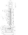
- FIG. 1 is a front view of an injection molding machine according to an embodiment of the present invention
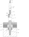
- 2 is an enlarged view of part A in FIG. 1 showing a thermocouple and its mounting structure.
- FIG. 4 is a cross-sectional view of the intermediate mounting member.
- FIG. 13A and 13B are diagrams showing modified examples of the mounting structure of a thermocouple.
- 13A and 13B are diagrams illustrating a thermocouple mounting structure according to a first modified example.
- FIG. 11 is a cross-sectional view of an intermediate mounting member of Modified Example 2.
- FIG. 1 shows a schematic front view of an injection molding machine 1 according to a first embodiment.
- the injection molding machine 1 is a horizontal metal injection molding machine that injects molten metal such as magnesium or aluminum.
- the injection molding machine 1 is generally composed of a clamping device 2 that clamps a mold, and an injection device 3 that heats, melts, and injects the metal material to be injected.
- the metal material that is heated, melted, and injected is sometimes called molten metal.
- the X direction refers to the axial direction of a cylinder 32. Terms such as “front” and “rear” are defined based on the injection direction.
- the mold clamping device 2 includes a fixed platen 21 fixed on a bed (not shown) to which a fixed mold M1 is attached, and a movable platen 22 slidable on the bed to which a movable mold M2 is attached.
- a mold clamping housing (not shown) slidable on the bed is provided on the opposite side of the fixed platen 21 with respect to the movable platen 22, and the fixed platen 21 and the mold clamping housing are connected by a plurality of tie bars 23.
- a link mechanism (not shown) for opening and closing the mold is provided between the movable platen 22 and the mold clamping housing. The link mechanism is driven by an electric ball screw. Instead of the link mechanism, a hydraulic mold clamping cylinder may be provided.
- a cavity M3 filled with molten metal is formed between the fixed mold M1 and the movable mold M2.
- the injection device 3 is provided on a base (not shown).
- the injection device 3 includes a hollow cylinder 32 for heating and melting the metal material to be injected, a screw 33 housed in the cylinder 32, and a drive mechanism 34 for driving the screw 33.
- the screw 33 is driven to rotate and in the X direction (moves back and forth) by the drive mechanism 34.
- a heater 39 for heating and melting the metal material is wound around the outer periphery of the cylinder 32. As shown in FIG. 2, the heater 39 is covered with a heat insulating material 40.
- the cylinder 32 is roughly divided into a supply section P1, a compression section P2, and a metering section P3 from the rear to the front.
- a hopper 36 is provided in the supply section P1, and the metal material in pellet form is supplied to the supply section P1.
- the metal material is sent to the compression section P2 while receiving residual heat from a heater 39.
- the metal material is compressed, heated, and kneaded in the compression section P2 to become molten, and is then transported to the metering section P3.
- the metering section P3 measures the molten metal injected in one injection cycle (shot).
- the screw 33 is equipped with a screw head 35 at its tip in the X direction.
- An injection nozzle 37 is attached to the tip of the cylinder 32 to supply molten metal to the cavity M3.
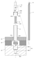
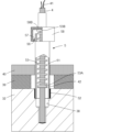
- thermocouple 4 and its mounting structure 5> 2 is an enlarged view of part A in FIG. 1 showing the thermocouple 4 and its mounting structure 5, and FIG. 3 is an exploded view of the thermocouple 4 and its mounting structure 5.
- a plurality of thermocouples 4 for measuring and controlling the cylinder temperature are attached to the cylinder 32. As shown in FIG. 1, a thermocouple 4 is provided for each heater control zone (not shown) of the cylinder 32. One thermocouple 4 may control one heater 39, or one thermocouple 4 may control multiple heaters 39 (e.g., two or three). In addition to the control thermocouple 4, a spare thermocouple may be attached to detect abnormal heating or the like.
- the thermocouple 4 is attached to the cylinder 32 by a thermocouple mounting structure 5.
- the thermocouple mounting structure 5 has a thermocouple holder 51 that holds the thermocouple 4, a threaded hole 38 (see FIG. 3) of the thermocouple holder 51 provided in the cylinder 32, and an intermediate mounting member 58.
- the threaded hole 38 has a threaded hole portion 38A that extends from the outer surface of the cylinder 32 to the inside of the cylinder 32, and a small diameter portion 38B that is coaxial with the threaded hole portion 38A and has a smaller diameter than the threaded hole portion 38A.
- a female thread 38C is provided on the inner surface of the threaded hole portion 38A.
- the thermocouple holder 51 is a hollow cylindrical member with a male thread 51A at its tip.
- the thermocouple holder 51 is attached to the cylinder 32 via an intermediate mounting member 52.
- the thermocouple holder 51 extends outward from the cylinder 32 through through holes 39A, 40A provided in the heater 39 and the insulating material 40, respectively.
- the thermocouple 4 is inserted into the hollow portion of the thermocouple holder 51 and further into the small diameter portion 38B of the threaded hole 38, with one end contacting the bottom 38D of the threaded hole 38.
- the thermocouple 4 extends outward from the thermocouple holder 51, and a lead wire 41 extends from the other outer end.
- a cap member 58 is provided at the tip of the thermocouple holder 51, and the cap member 58 is screwed to the thermocouple holder 51 by a screw (not shown) provided on the inner surface.
- the cap member 58 is a cylindrical member, and one end is provided with a bottom 58B having an opening 58A through which the thermocouple 4 passes, and the other end is an open end 53C.
- a coil spring 53 is wound around the thermocouple 4.
- One end 53A of the coil spring 53 has a larger diameter than the other parts.
- the coil spring 53 is inserted into the opening 58A from the open end 53C side of the cap member 58, and the expanded end 53A is held by the inner surface of the bottom 58B of the cap member 58.
- a cylindrical spring adjustment fitting 54 is provided around the thermocouple 4, and the coil spring 53 is inserted between the thermocouple 4 and the spring adjustment fitting 54.
- the other end 53B of the spring is fixed to the thermocouple 4 with a screw 55 via the spring adjustment fitting 54.
- thermocouple 4 By applying a tensile force to the coil spring 53, one end 53A of the coil spring 53 comes into close contact with the inner surface of the bottom 58B of the cap member 58. This tensile force causes the coil spring 53 to apply a downward force (elastic restoring force) to the thermocouple 4 at the portion where the thermocouple 4 is fixed to the spring adjustment fitting 54. This ensures that the tip of the thermocouple 4 is in stable contact with the bottom 38D of the screw hole 38, allowing the cylinder temperature to be measured with high accuracy.
- the elastic restoring force of the coil spring 53 can be adjusted by the position of the spring adjustment fitting 54.
- thermocouple 4 and the thermocouple holder 51 may be removed from the cylinder 32 for the purpose of maintenance of the cylinder 32, etc. If the male thread 51A of the thermocouple holder 51 seizes and the thermocouple holder 51 cannot be removed, not only will maintenance be hindered, but it may also be necessary to install a new thermocouple 4 in another location on the cylinder 32.
- thermocouple mounting structure 5 of this embodiment an intermediate mounting member 52 made of a different material than the thermocouple holder 51 is interposed between the screw hole 38 provided in the cylinder 32 and the thermocouple holder 51.
- "Different material” means that the element with the highest component ratio in the intermediate mounting member 52 is different from the element with the highest component ratio in the thermocouple holder 51.
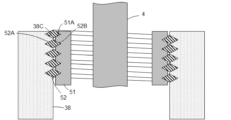
- FIG. 4 is an enlarged view of part B in FIG. 2, showing the intermediate mounting member 52, thermocouple holder 51, and cylinder 32
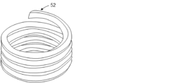
- FIG. 5 is a perspective view of the intermediate mounting member 52.
- the intermediate mounting member 52 is made by winding a wire having a diamond-shaped cross section into a coil. Adjacent wires are in close contact or have a small gap between them, and the intermediate mounting member 52 is formed in an approximately hollow cylindrical or coil shape overall.
- the outer surface of the intermediate mounting member 52 has an outer thread groove 52A that mates with the threaded hole portion 38A of the threaded hole 38 of the cylinder 32, and the inner surface of the intermediate mounting member 52 has an inner thread groove 52B that mates with the male thread 51A of the thermocouple holder 51.
- the intermediate mounting member 52 is screwed into the threaded hole 38 of the cylinder 32 using a special tool, and then the thermocouple holder 51 is screwed into the inner thread groove 52B of the intermediate mounting member 52.
- the intermediate mounting member 52 and the thermocouple holder 51 are made of metal, but are made of different materials.
- the thermocouple holder 51 is made of a general steel material
- the intermediate mounting member 52 is made of a nickel alloy. That is, the metal element with the highest component ratio in the intermediate mounting member 52 is nickel, and the metal element with the highest component ratio in the thermocouple holder 51 is iron. Nickel alloys are preferable because of their excellent high-temperature durability.
- thermocouple holder 51 The seizure of the male thread 51A of the thermocouple holder 51 can be suppressed, for example, by making the thermocouple holder 51 from a nickel alloy.
- nickel alloys are expensive.
- An example of a commercially available product is Recoil (registered trademark) "Inconel X-750" from Ikeda Metal Mining Co., Ltd.
- commercially available products are used as members for reinforcing or repairing female threads, in this embodiment, they are used to suppress seizure of the threads.
- the intermediate mounting member 52 and the cylinder 32 are also made of different materials. Therefore, seizure is unlikely to occur between the outer thread groove 52A of the intermediate mounting member 52 and the threaded hole 38 of the cylinder 32. In the unlikely event that seizure occurs between the inner thread groove 52B of the intermediate mounting member 52 and the male thread 51A of the thermocouple holder 51, making it impossible for the thermocouple holder 51 to rotate relative to the cylinder 32, there is a possibility that the intermediate removal member may be able to rotate relative to the threaded hole 38 of the cylinder 32.
- thermocouple holder 51 cannot be removed from the intermediate mounting member 52 by itself, it may be possible to remove the thermocouple holder 51 together with the intermediate mounting member 52.
- the means for removing the thermocouple holder 51 from the cylinder 32 is made redundant, improving reliability.
- Fig. 6 is a view similar to Fig. 2 but showing a first modified example of this embodiment.
- the method of fixing the thermocouple 4 to the thermocouple holder 51 is different.
- the coil spring 53 is provided on the cylinder 32 side of the cap member 58.
- the thermocouple 4 is provided with a receiving portion 42 for the coil spring 53, and one end of the coil spring 53 is held by the receiving portion 42 and the other end is held by a bottom portion 58B of the cap member 58.
- the cap member 58 has a claw portion 56 that protrudes radially inward, and the thermocouple holder 51 has a hook 57 that protrudes radially outward.
- thermocouple holder 51 is fixed to the intermediate mounting member 52 in the same manner.
- ⁇ Modification 2> 7 is a cross-sectional view of an intermediate mounting member 152 according to a second modified example of this embodiment.
- the intermediate mounting member 152 is a hollow cylindrical member having an outer screw groove 152A on its outer surface that engages with the screw hole portion 38A of the screw hole 38 of the cylinder 32, and an inner screw groove 152B on its inner surface that engages with the male screw 51A of the thermocouple holder 51.
- the intermediate mounting member 152 is not wound with wire, but is a hollow cylindrical member with threads machined on both sides.
- the intermediate mounting member 152 is formed of, for example, a nickel alloy. Such an intermediate mounting member 152 also has the same effects as the intermediate mounting member 52.
- thermocouple mounting structure for a metal injection molding machine
- the present invention is not limited thereto.
- the present invention is also applicable to a resin injection molding machine.
- the present invention is also applicable to a resin or metal extruder.
- the present invention is applicable to a machine having a cylinder for heating and melting a material, a thermocouple mounting structure attached to the cylinder, and a thermocouple attached to the mounting structure.
- thermocouple holder 51 is directly screwed into the threaded hole 38 of the cylinder 32, the possibility of the thermocouple holder 51 becoming seized can be reduced by applying the thermocouple mounting structure 5 of the present invention in the following procedure.
- thermocouple 4 and thermocouple holder 51 are removed from the cylinder 32.
- the above-mentioned intermediate mounting member 52 (or 152) is attached to the threaded hole 38 of the cylinder 32.
- the intermediate mounting member 51 is attached to the cylinder 32 by engaging the outer screw groove 52A with the threaded hole 38 provided in the cylinder 32.
- the thermocouple holder 51, coil spring 53, cap member 58, and thermocouple 4 are attached.
- thermocouple mounting structure 32 cylinder 38 threaded hole 51 thermocouple holder 52, 152 intermediate mounting member 52A, 152A outer screw groove 52B, 152B inner screw groove
Landscapes
- Engineering & Computer Science (AREA)
- Mechanical Engineering (AREA)
- Manufacturing & Machinery (AREA)
- General Engineering & Computer Science (AREA)
- Physics & Mathematics (AREA)
- General Physics & Mathematics (AREA)
- Injection Moulding Of Plastics Or The Like (AREA)
- Control Of Combustion (AREA)
- Measuring Temperature Or Quantity Of Heat (AREA)
Abstract
Description
図1は、第1の実施形態に係る射出成形機1の概略正面図を示している。射出成形機1はマグネシウム、アルミニウムなどの溶融金属を射出する、横型の金属射出成形機である。射出成形機1は、金型を型締めする型締装置2と、射出される金属材料を加熱溶融して射出する射出装置3と、から概略構成されている。加熱溶融されて射出される金属材料を溶融金属という場合がある。以下の説明でX方向はシリンダ32の軸方向をいう。「前方」及び「後方」等の用語は射出方向を基準に定義される。
型締装置2は、ベッド(図示せず)上に固定され固定金型M1が取り付けられる固定盤21と、ベッド上をスライド可能で可動金型M2が取り付けられる可動盤22と、を備えている。可動盤22に関し固定盤21の反対側には、ベッド上をスライド可能な型締ハウジング(図示せず)が設けられ、固定盤21と型締ハウジングは複数本のタイバー23によって連結されている。可動盤22と型締ハウジングとの間には、金型を開閉するためのリンク機構(図示せず)が設けられている。リンク機構は電動式のボールねじで駆動される。リンク機構の代わりに、油圧式の型締シリンダを設けてもよい。固定金型M1と可動金型M2との間には、溶融金属が充填されるキャビティM3が形成される。
射出装置3は基台(図示せず)上に設けられている。射出装置3は、射出される金属材料を加熱溶融するための中空円筒のシリンダ32と、シリンダ32に収容されたスクリュ33と、スクリュ33を駆動する駆動機構34と、を備えている。スクリュ33は駆動機構34によって回転駆動されるとともにX方向に駆動(前後移動)される。シリンダ32の外周には金属材料を加熱溶融するヒータ39が巻かれている。図2に示すように、ヒータ39は断熱材40で覆われている。
図2は、熱電対4とその取付構造5を示す図1のA部拡大図、図3は熱電対4とその取付構造5の分解図である。シリンダ32には、シリンダ温度を測定し制御するための複数の熱電対4が取り付けられている。図1に示すように、熱電対4はシリンダ32のヒータ制御ゾーン(図示せず)毎に設けられている。一つの熱電対4で一つのヒータ39を制御してもよく、一つの熱電対4で複数(例えば、2つまたは3つ)のヒータ39を制御してもよい。制御用の熱電対4とは別に、異常加熱などを検知する予備の熱電対を取り付ける場合もある。熱電対4は熱電対の取付構造5によって、シリンダ32に取り付けられている。
一般に、ねじ穴を備えた構造物と、このねじ穴に噛み合うねじとが長期間高温状態におかれると、ねじの焼き付きが起こりやすくなる。特にねじ穴を備えた構造物とねじとが同種の材質であって、ねじと構造物との接触面に大きな荷重が掛る場合、凝着が生じ、焼き付きが発生する可能性が高い。本実施形態の金属射出成形機1の場合、シリンダ温度は600~700℃に達する。熱電対4と熱電対保持具51はシリンダ32のメンテナンスなどの目的でシリンダ32から取り外されることがある。熱電対保持具51の雄ねじ51Aが焼き付きを生じ、熱電対保持具51を取り外せなくなると、メンテナンスに支障を生じるだけでなく、シリンダ32の別の場所に新たに熱電対4を設置することが必要となる可能性もある。
本実施形態の効果について説明する。熱電対保持具51の雄ねじ51Aの焼き付きは、例えば、熱電対保持具51をニッケル合金で作成することでも抑制できる。しかし、ニッケル合金は高価である。本実施形態は中間取付部材52を取り付けるだけでよく、中間取付部材52は市販品でもよいため、追加のコストが抑えられる。市販品としては、例えば池田金属鉱業株式会社のリコイル(登録商標)「インコネルX-750」が挙げられる。市販品は雌ねじの補強や補修のための部材として使用されているが、本実施形態ではねじの焼き付きを抑制するために用いている。
図6は本実施形態の変形例1を示す図2と同様の図である。本変形例では熱電対4の熱電対保持具51への固定方法が異なる。コイルばね53はキャップ部材58よりシリンダ32側に設けられている。熱電対4にコイルばね53の受部42が設けられ、コイルばね53の一端が受部42に、他端がキャップ部材58の底部58Bに保持されている。キャップ部材58は径方向内方に突き出す爪部56を有し、熱電対保持具51は径方向外側に突き出すフック57を有している。
図7は本実施形態の変形例2に係る中間取付部材152の断面図である。中間取付部材152は中空円筒部材で、シリンダ32のねじ穴38のねじ穴部38Aと噛み合う外側ねじ溝152Aを外面に有し、熱電対保持具51の雄ねじ51Aと噛み合う内側ねじ溝152Bを内面に有している。中間取付部材152は上記実施形態と異なり、線材を巻いたものではなく、中空円筒部材の両面にねじを加工したものである。中間取付部材152は、例えばニッケル合金で形成されている。このような中間取付部材152も中間取付部材52と同様の効果を奏する。
4 熱電対
5 熱電対の取付構造
32 シリンダ
38 ねじ穴
51 熱電対保持具
52、152 中間取付部材
52A、152A 外側ねじ溝
52B,152B 内側ねじ溝
Claims (8)
- 材料を加熱溶融するためのシリンダに取り付けられる熱電対の取付構造であって、
前記シリンダに設けられたねじ穴と噛み合う外側ねじ溝を外面に有し、内側ねじ溝を内面に有する中間取付部材と、
前記中間取付部材の前記内側ねじ溝にねじ止めされ、熱電対を保持する熱電対保持具と、
を有し、
前記中間取付部材は前記熱電対保持具と異なる材質からなる、熱電対の取付構造。 - 前記熱電対保持具と前記中間取付部材は金属からなり、前記中間取付部材の最も成分比の高い金属元素は、前記熱電対保持具の最も成分比の高い金属元素と異なる、請求項1に記載の熱電対の取付構造。
- 前記中間取付部材の前記最も成分比の高い金属元素はニッケルであり、前記シリンダの最も成分比の高い金属元素は鉄である、請求項2に記載の熱電対の取付構造。
- 前記中間取付部材は前記シリンダと異なる材質からなる、請求項1に記載の熱電対の取付構造。
- 前記中間取付部材は菱形断面の線材をコイル状に巻いた部材である、請求項1から4のいずれか1項に記載の熱電対の取付構造。
- 請求項1から5のいずれか1項に記載の熱電対の取付構造と、
前記シリンダと、
前記取付構造に取り付けられた熱電対と、
を有する機械装置。 - 前記機械装置は射出成形機である、請求項6に記載の機械装置。
- 材料を加熱溶融するためのシリンダに熱電対の取付構造を設置する方法であって、以下の工程、
(A)外側ねじ溝を外面に有し内側ねじ溝を内面に有する中間取付部材を、前記外側ねじ溝を前記シリンダに設けられたねじ穴と噛み合わせることによって、前記シリンダに取り付けること、
(B)前記中間取付部材の前記内側ねじ溝に熱電対を保持する熱電対保持具をねじ止めすること、
を有し、
前記中間取付部材は前記熱電対保持具と異なる材質からなる方法。
Priority Applications (2)
| Application Number | Priority Date | Filing Date | Title |
|---|---|---|---|
| EP24825608.3A EP4729274A1 (en) | 2023-06-19 | 2024-05-15 | Mounting structure for thermocouple, mechanical device provided with same, and method for installing mounting structure for thermocouple |
| CN202480040009.7A CN121368519A (zh) | 2023-06-19 | 2024-05-15 | 热电偶的安装构造和具备该安装构造的机械装置以及设置热电偶的安装构造的方法 |
Applications Claiming Priority (2)
| Application Number | Priority Date | Filing Date | Title |
|---|---|---|---|
| JP2023100002A JP2025000247A (ja) | 2023-06-19 | 2023-06-19 | 熱電対の取付構造とこれを備えた機械装置、及び熱電対の取付構造を設置する方法 |
| JP2023-100002 | 2023-06-19 |
Publications (1)
| Publication Number | Publication Date |
|---|---|
| WO2024262199A1 true WO2024262199A1 (ja) | 2024-12-26 |
Family
ID=93935123
Family Applications (1)
| Application Number | Title | Priority Date | Filing Date |
|---|---|---|---|
| PCT/JP2024/017955 Ceased WO2024262199A1 (ja) | 2023-06-19 | 2024-05-15 | 熱電対の取付構造とこれを備えた機械装置、及び熱電対の取付構造を設置する方法 |
Country Status (5)
| Country | Link |
|---|---|
| EP (1) | EP4729274A1 (ja) |
| JP (1) | JP2025000247A (ja) |
| CN (1) | CN121368519A (ja) |
| TW (1) | TW202517436A (ja) |
| WO (1) | WO2024262199A1 (ja) |
Citations (9)
| Publication number | Priority date | Publication date | Assignee | Title |
|---|---|---|---|---|
| US3945070A (en) * | 1975-05-19 | 1976-03-23 | Avia Instrument Company | Wire thread cast insert |
| JPH03251419A (ja) * | 1990-03-01 | 1991-11-08 | Meiki Co Ltd | 射出成形機 |
| JPH11105106A (ja) * | 1997-10-06 | 1999-04-20 | Japan Steel Works Ltd:The | 加熱シリンダにおける熱電対取付け部の構造 |
| JP2001220655A (ja) * | 2000-02-04 | 2001-08-14 | Emhart Inc | かじり防止ファスナインサート |
| JP2002130255A (ja) * | 2000-10-26 | 2002-05-09 | Tokuden Co Ltd | 誘導発熱ローラ装置 |
| JP2002333372A (ja) | 2001-05-07 | 2002-11-22 | Japan Steel Works Ltd:The | 温度検出素子取付装置 |
| JP3108736U (ja) * | 2004-11-12 | 2005-04-28 | 山里産業株式会社 | 温度センサ |
| JP2008502854A (ja) * | 2004-06-15 | 2008-01-31 | ボルホフ・フェルビンダンクシュテヒニーク・ゲゼルシャフト・ミット・ベシュレンクテン・ハフツング | マグネシウム合金又はアルミニウム合金製のワイヤ状ねじ筋インサート |
| JP2010032037A (ja) * | 2008-06-23 | 2010-02-12 | Nippon Sprew Corp | セルフタッピングインサート |
-
2023
- 2023-06-19 JP JP2023100002A patent/JP2025000247A/ja active Pending
-
2024
- 2024-05-15 EP EP24825608.3A patent/EP4729274A1/en active Pending
- 2024-05-15 CN CN202480040009.7A patent/CN121368519A/zh active Pending
- 2024-05-15 WO PCT/JP2024/017955 patent/WO2024262199A1/ja not_active Ceased
- 2024-06-06 TW TW113120930A patent/TW202517436A/zh unknown
Patent Citations (9)
| Publication number | Priority date | Publication date | Assignee | Title |
|---|---|---|---|---|
| US3945070A (en) * | 1975-05-19 | 1976-03-23 | Avia Instrument Company | Wire thread cast insert |
| JPH03251419A (ja) * | 1990-03-01 | 1991-11-08 | Meiki Co Ltd | 射出成形機 |
| JPH11105106A (ja) * | 1997-10-06 | 1999-04-20 | Japan Steel Works Ltd:The | 加熱シリンダにおける熱電対取付け部の構造 |
| JP2001220655A (ja) * | 2000-02-04 | 2001-08-14 | Emhart Inc | かじり防止ファスナインサート |
| JP2002130255A (ja) * | 2000-10-26 | 2002-05-09 | Tokuden Co Ltd | 誘導発熱ローラ装置 |
| JP2002333372A (ja) | 2001-05-07 | 2002-11-22 | Japan Steel Works Ltd:The | 温度検出素子取付装置 |
| JP2008502854A (ja) * | 2004-06-15 | 2008-01-31 | ボルホフ・フェルビンダンクシュテヒニーク・ゲゼルシャフト・ミット・ベシュレンクテン・ハフツング | マグネシウム合金又はアルミニウム合金製のワイヤ状ねじ筋インサート |
| JP3108736U (ja) * | 2004-11-12 | 2005-04-28 | 山里産業株式会社 | 温度センサ |
| JP2010032037A (ja) * | 2008-06-23 | 2010-02-12 | Nippon Sprew Corp | セルフタッピングインサート |
Also Published As
| Publication number | Publication date |
|---|---|
| CN121368519A (zh) | 2026-01-20 |
| EP4729274A1 (en) | 2026-04-22 |
| JP2025000247A (ja) | 2025-01-07 |
| TW202517436A (zh) | 2025-05-01 |
Similar Documents
| Publication | Publication Date | Title |
|---|---|---|
| US20110304075A1 (en) | Breakable Mechanical Connection Between Injection Molding Valve Pin Plate and Valve Pins | |
| JP2019077053A (ja) | 金型監視装置および金型監視方法 | |
| JPH0753395B2 (ja) | ホットランナ式射出成形装置 | |
| WO2024262199A1 (ja) | 熱電対の取付構造とこれを備えた機械装置、及び熱電対の取付構造を設置する方法 | |
| US7914278B2 (en) | Internally heated nozzle adapter | |
| US20090107646A1 (en) | Metal-Molding Conduit Assembly of Metal-Molding System | |
| CN101835393A (zh) | 热浇道喷嘴系统 | |
| US6914537B2 (en) | Method for monitoring operation data of an injection-molding machine | |
| JP4808184B2 (ja) | 成形システムの導管接続部 | |
| JP5419364B2 (ja) | 射出成形システム、射出成形方法 | |
| US7926545B2 (en) | Injection cylinder in injection apparatus for molding metal material | |
| JP6173985B2 (ja) | ヒートアンドクール成形方法を実施するトグル式射出成形機の型締力調整方法 | |
| ITBI20100010A1 (it) | Gruppo di otturazione perfezionato, con comando multi-stelo, per lo stampaggio ad iniezione di materiale plastico | |
| US20130287887A1 (en) | Valve-Stem Assembly Removable from Runner System While Valve-Actuator Assembly Remains Connected with Manifold Assembly | |
| JP5324190B2 (ja) | 締め付け防止機能を備えたネジ及びそれを用いたモールド射出成形金型 | |
| KR102285783B1 (ko) | 사출성형기용 열전대 조립체 | |
| RU200952U1 (ru) | Быстросменный картридж для печатающей головки fdm 3d-принтера | |
| TWI723522B (zh) | 熱澆道防溢構造(二) | |
| JP6612095B2 (ja) | 軽金属射出成形機の射出装置 | |
| JP2004090654A (ja) | 射出成形機の金型保護方法及び型締力制御方法 | |
| EP2611590B1 (en) | Nozzle-locating insulator having spring-noncontact sections interposed between spring-contact sections | |
| AU2018102109A4 (en) | Encapsulation shroud for an injection molding machine | |
| JP2004082178A (ja) | 射出成形機および前記射出成形機の整備方法 | |
| JP2010005963A (ja) | 射出成形機 | |
| US20080089969A1 (en) | Barrel head of extruder of molding system, barrel head having outer and inner portions, amongst other things |
Legal Events
| Date | Code | Title | Description |
|---|---|---|---|
| 121 | Ep: the epo has been informed by wipo that ep was designated in this application |
Ref document number: 24825608 Country of ref document: EP Kind code of ref document: A1 |
|
| WWE | Wipo information: entry into national phase |
Ref document number: 2024825608 Country of ref document: EP |
|
| NENP | Non-entry into the national phase |
Ref country code: DE |
|
| ENP | Entry into the national phase |
Ref document number: 2024825608 Country of ref document: EP Effective date: 20260119 |
|
| ENP | Entry into the national phase |
Ref document number: 2024825608 Country of ref document: EP Effective date: 20260119 |
|
| ENP | Entry into the national phase |
Ref document number: 2024825608 Country of ref document: EP Effective date: 20260119 |
|
| WWP | Wipo information: published in national office |
Ref document number: 2024825608 Country of ref document: EP |