WO2024262115A1 - プロセスカートリッジ - Google Patents
プロセスカートリッジ Download PDFInfo
- Publication number
- WO2024262115A1 WO2024262115A1 PCT/JP2024/011979 JP2024011979W WO2024262115A1 WO 2024262115 A1 WO2024262115 A1 WO 2024262115A1 JP 2024011979 W JP2024011979 W JP 2024011979W WO 2024262115 A1 WO2024262115 A1 WO 2024262115A1
- Authority
- WO
- WIPO (PCT)
- Prior art keywords
- toner
- developing roller
- developing
- roller
- point
- Prior art date
- Legal status (The legal status is an assumption and is not a legal conclusion. Google has not performed a legal analysis and makes no representation as to the accuracy of the status listed.)
- Ceased
Links
Images





Classifications
-
- G—PHYSICS
- G03—PHOTOGRAPHY; CINEMATOGRAPHY; ANALOGOUS TECHNIQUES USING WAVES OTHER THAN OPTICAL WAVES; ELECTROGRAPHY; HOLOGRAPHY
- G03G—ELECTROGRAPHY; ELECTROPHOTOGRAPHY; MAGNETOGRAPHY
- G03G21/00—Arrangements not provided for by groups G03G13/00 - G03G19/00, e.g. cleaning, elimination of residual charge
- G03G21/16—Mechanical means for facilitating the maintenance of the apparatus, e.g. modular arrangements
- G03G21/18—Mechanical means for facilitating the maintenance of the apparatus, e.g. modular arrangements using a processing cartridge, whereby the process cartridge comprises at least two image processing means in a single unit
- G03G21/1803—Arrangements or disposition of the complete process cartridge or parts thereof
- G03G21/1814—Details of parts of process cartridge, e.g. for charging, transfer, cleaning, developing
-
- G—PHYSICS
- G03—PHOTOGRAPHY; CINEMATOGRAPHY; ANALOGOUS TECHNIQUES USING WAVES OTHER THAN OPTICAL WAVES; ELECTROGRAPHY; HOLOGRAPHY
- G03G—ELECTROGRAPHY; ELECTROPHOTOGRAPHY; MAGNETOGRAPHY
- G03G13/00—Electrographic processes using a charge pattern
- G03G13/06—Developing
- G03G13/08—Developing using a solid developer, e.g. powder developer
-
- G—PHYSICS
- G03—PHOTOGRAPHY; CINEMATOGRAPHY; ANALOGOUS TECHNIQUES USING WAVES OTHER THAN OPTICAL WAVES; ELECTROGRAPHY; HOLOGRAPHY
- G03G—ELECTROGRAPHY; ELECTROPHOTOGRAPHY; MAGNETOGRAPHY
- G03G15/00—Apparatus for electrographic processes using a charge pattern
- G03G15/06—Apparatus for electrographic processes using a charge pattern for developing
- G03G15/08—Apparatus for electrographic processes using a charge pattern for developing using a solid developer, e.g. powder developer
-
- G—PHYSICS
- G03—PHOTOGRAPHY; CINEMATOGRAPHY; ANALOGOUS TECHNIQUES USING WAVES OTHER THAN OPTICAL WAVES; ELECTROGRAPHY; HOLOGRAPHY
- G03G—ELECTROGRAPHY; ELECTROPHOTOGRAPHY; MAGNETOGRAPHY
- G03G21/00—Arrangements not provided for by groups G03G13/00 - G03G19/00, e.g. cleaning, elimination of residual charge
- G03G21/16—Mechanical means for facilitating the maintenance of the apparatus, e.g. modular arrangements
- G03G21/18—Mechanical means for facilitating the maintenance of the apparatus, e.g. modular arrangements using a processing cartridge, whereby the process cartridge comprises at least two image processing means in a single unit
- G03G21/1803—Arrangements or disposition of the complete process cartridge or parts thereof
- G03G21/1817—Arrangements or disposition of the complete process cartridge or parts thereof having a submodular arrangement
- G03G21/1825—Pivotable subunit connection
-
- G—PHYSICS
- G03—PHOTOGRAPHY; CINEMATOGRAPHY; ANALOGOUS TECHNIQUES USING WAVES OTHER THAN OPTICAL WAVES; ELECTROGRAPHY; HOLOGRAPHY
- G03G—ELECTROGRAPHY; ELECTROPHOTOGRAPHY; MAGNETOGRAPHY
- G03G21/00—Arrangements not provided for by groups G03G13/00 - G03G19/00, e.g. cleaning, elimination of residual charge
- G03G21/16—Mechanical means for facilitating the maintenance of the apparatus, e.g. modular arrangements
- G03G21/18—Mechanical means for facilitating the maintenance of the apparatus, e.g. modular arrangements using a processing cartridge, whereby the process cartridge comprises at least two image processing means in a single unit
- G03G21/1839—Means for handling the process cartridge in the apparatus body
- G03G21/1857—Means for handling the process cartridge in the apparatus body for transmitting mechanical drive power to the process cartridge, drive mechanisms, gears, couplings, braking mechanisms
- G03G21/186—Axial couplings
-
- G—PHYSICS
- G03—PHOTOGRAPHY; CINEMATOGRAPHY; ANALOGOUS TECHNIQUES USING WAVES OTHER THAN OPTICAL WAVES; ELECTROGRAPHY; HOLOGRAPHY
- G03G—ELECTROGRAPHY; ELECTROPHOTOGRAPHY; MAGNETOGRAPHY
- G03G9/00—Developers
- G03G9/08—Developers with toner particles
- G03G9/0819—Developers with toner particles characterised by the dimensions of the particles
-
- G—PHYSICS
- G03—PHOTOGRAPHY; CINEMATOGRAPHY; ANALOGOUS TECHNIQUES USING WAVES OTHER THAN OPTICAL WAVES; ELECTROGRAPHY; HOLOGRAPHY
- G03G—ELECTROGRAPHY; ELECTROPHOTOGRAPHY; MAGNETOGRAPHY
- G03G9/00—Developers
- G03G9/08—Developers with toner particles
- G03G9/097—Plasticisers; Charge controlling agents
Definitions
- the present invention relates to a process cartridge.
- Such image forming devices generally require the replenishment of developer and the maintenance of various process means.
- the process cartridge system makes it possible to provide an image forming device with excellent usability.
- a known type of color image forming device is an in-line type image forming device in which photoconductors corresponding to each image forming operation using multiple color developers are arranged in a row along the surface movement direction of the transfer material to which the toner image is transferred.
- Some in-line type color image forming devices have multiple photoconductors arranged in a row in a direction (for example, horizontal direction) that intersects with the vertical direction (gravity direction).
- the in-line type is a preferred image forming method because it is easy to meet demands such as high image formation speed and deployment to multi-function printers.
- the fixing device and the developing device can be located at separate positions within the image forming device body, with the intermediate transfer body and the recording material carrier sandwiched between them. This has the advantage that the developing device (or the exposure device) is less susceptible to the heat of the fixing device.
- a process cartridge that can be mounted in an image forming apparatus, a photosensitive drum as an image carrier, a developing roller for developing a toner image on the photosensitive drum, a supply roller for supplying toner to the developing roller; a developing chamber having a support portion for axially supporting the developing roller and the supply roller; a developing blade for regulating the thickness of a toner layer on the developing roller; a toner having toner particles having a volume average particle size R and an external additive; a toner storage section for storing the toner, the toner storage section is configured to communicate with the developing chamber through a communication port, the developing roller is configured so that the moving direction of the surface of the developing roller is opposite to the moving direction of the surface of the supply roller at the contact position with the supply roller; in a cross section of the process cartridge in a plane perpendicular to the rotation axis of the developing roller when the process cartridge is mounted in the main body of the image forming apparatus, a location where the developing blade contacts the developing roller is vertically
- a process cartridge having the toner contains hydrotalcite particles as the external additive, In a line analysis in a STEM-EDS mapping analysis of the toner, fluorine is present inside the hydrotalcite particles,
- the developing blade is made of a plate-shaped metallic elastic blade and a blade support portion for supporting the elastic blade.
- the elastic blade is in contact with the developing roller to form a nip N1.
- a point on the elastic blade at the end of the nip N1 on the upstream side in the rotation direction of the developing roller is defined as point D.
- a point on the elastic blade that is closest to the surface of the developing roller is designated as point B.
- a point E is a point where a perpendicular line drawn from point B to the surface of the developing roller intersects with the surface of the developing roller.
- the present invention also has the following configuration.
- a process cartridge that can be mounted in an image forming apparatus, A photosensitive drum as an image carrier, a developing roller for developing a toner image on the photosensitive drum, a supply roller for supplying toner to the developing roller; a developing chamber having a support portion for axially supporting the developing roller and the supply roller; a developing blade for regulating the thickness of a toner layer on the developing roller; a toner having toner particles having a volume average particle size R and an external additive; a toner storage section for storing the toner, the toner storage section is configured to communicate with the developing chamber through a communication port,
- the direction of movement of the surface of the developing roller at the contact position with the supply roller is as follows: The direction of movement of the surface of the supply roller is opposite to the direction of movement of the supply roller.
- the developing blade is made of a plate-shaped metallic elastic blade and a blade support portion for supporting the elastic blade.
- a straight line A connecting the rotational centers of the supply roller and the developing roller is inclined at an angle of approximately 9.85° from the horizontal, the rotational axis center of the supply roller is below the rotational axis center of the developing roller, and the rotational axis center of the photosensitive drum is above the straight line A.
- a driving force receiving portion is provided.
- the toner contains hydrotalcite particles as the external additive, In a line analysis in a STEM-EDS mapping analysis of the toner, fluorine is present inside the hydrotalcite particles, In a cross section of the process cartridge taken along a plane perpendicular to the rotation axis of the developing roller, The elastic blade is in contact with the developing roller to form a nip N1.
- a point on the elastic blade at the end of the nip N1 on the upstream side in the rotation direction of the developing roller is defined as point D.
- a point on the elastic blade that is closest to the surface of the developing roller is designated as point B.
- a point E is a point where a perpendicular line drawn from point B to the surface of the developing roller intersects with the surface of the developing roller.
- the distance GF is equal to or greater than R.
- FIG. 2B is a schematic cross-sectional view illustrating a contact state between a developing blade and a developing roller according to a comparative example of the present invention; FIG.
- FIG. 1 is a diagram for explaining a method of inputting driving force to a toner supply roller according to an embodiment to which the present invention can be applied;
- FIG. 2 is a diagram showing the movement of toner in a developing device according to an embodiment to which the present invention can be applied;
- FIG. 1 is a diagram for explaining the positional relationship between the inner wall of a developing chamber and the supporting end of a developing blade in an embodiment to which the present invention can be applied.
- 1A and 1B are cross-sectional conceptual diagrams of a contact portion between a developing roller and a developing blade, illustrating the movement of toner regulated by the developing blade according to an embodiment to which the present invention can be applied.
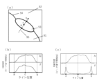
- (a)-(c) are schematic diagrams of the on-line analysis of external additives.
- FIG. 13 is a cross-sectional conceptual diagram of a developing blade in a lateral direction when the tip of the developing blade is bent in a modified example of an embodiment to which the present invention can be applied.
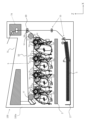
- FIG. 1 is a diagram showing a schematic configuration of an image forming apparatus 100 according to the present embodiment in a static orientation placed on a horizontal surface, similar to when the apparatus is actually used.
- the image forming apparatus 100 according to the present embodiment is an in-line full-color laser printer that employs an intermediate transfer method.
- four detachable process cartridges 70 70Y, 70M, 70C, 70K are mounted by mounting members (not shown).
- the upstream side of the process cartridges 70 in the mounting direction of the image forming apparatus 100 is defined as the front side
- the downstream side of the process cartridges 70 in the mounting direction is defined as the rear side.
- Each process cartridge 70 has an electrophotographic photosensitive drum (hereinafter referred to as photosensitive drum) 1 (1a, 1b, 1c, 1d) disposed therein.
- process means such as a charging roller 2 (2a, 2b, 2c, 2d), a developing roller 25 (25a, 25b, 25c, 25d), and a cleaning member 6 (6a, 6b, 6c, 6d) are integrally disposed around the photosensitive drum 1.
- the charging roller 2 uniformly charges the surface of the photosensitive drum 1. In this embodiment, it is charged to a negative polarity.
- the developing roller 25 develops the latent image formed on the photosensitive drum 1 with a developer (hereinafter referred to as toner) to make it visible.
- toner developer
- the normal polarity of the toner is negative.
- the cleaning member 6 removes the toner remaining on the photosensitive drum 1 after the toner image formed on the photosensitive drum 1 is transferred to a recording medium.
- the detailed configuration and positional relationship of the photosensitive drum 1, charging roller 2, developing roller 25, and cleaning member 6 will be described later with reference to FIG. 2.
- a scanner unit 3 is provided for selectively exposing the photosensitive drum 1 based on image information and forming a latent image on the photosensitive drum 1.
- a cassette 17 containing recording medium S is attached to the bottom of the device main body 100a.
- a recording medium transport means is provided so that the recording medium S passes through a secondary transfer roller 69 and a fixing section 74 and is transported to the top of the device main body 100a.
- An intermediate transfer unit 5 is provided above the process cartridges 70 (70Y, 70M, 70C, 70K) as an intermediate transfer means for transferring the toner images formed on each photosensitive drum 1 (1a, 1b, 1c, 1d).
- the intermediate transfer unit 5 has a drive roller 56, a driven roller 57, primary transfer rollers 58 (58a, 58b, 58c, 58d) facing the photosensitive drums 1 of each color, and an opposing roller 59 facing the secondary transfer roller 69, and a transfer belt 50 is stretched across it.
- the transfer belt 50 then moves in a circular motion so as to face and come into contact with all of the photosensitive drums 1, and a voltage is applied to the primary transfer rollers 58 (58a, 58b, 58c, 58d) to perform a primary transfer from the photosensitive drums 1 onto the transfer belt 50.
- a voltage is applied to the opposing roller 59 and the secondary transfer roller 69 arranged inside the transfer belt 50, so that the toner on the transfer belt 50 is transferred to the recording medium S.
- each photosensitive drum 1 When forming an image, each photosensitive drum 1 is rotated, and the photosensitive drum 1, which is uniformly charged by the charging roller 2, is selectively exposed to light from the scanner unit 3. This forms an electrostatic latent image on the photosensitive drum 1.
- the latent image is developed by the developing roller 25.
- the pair of registration rollers 55 transports the recording medium S to the secondary transfer position where the opposing roller 59 and the secondary transfer roller 69 are in contact with each other with the transfer belt 50 interposed therebetween. Then, by applying a transfer bias voltage to the secondary transfer roller 69, the toner image of each color on the transfer belt 50 is secondarily transferred to the recording medium S.
- the recording medium S on which the color image has been formed is heated and pressurized by the fixing unit 74 to fix the toner image. After that, the recording medium S is discharged to the discharge unit 75 by the discharge roller 72.
- the fixing unit 74 is disposed at the top of the device main body 100a.
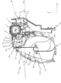
- Fig. 2 is a principal cross-section of the process cartridge 70 containing toner, in a position in which it is mounted in the image forming apparatus 100.
- the cartridge 70Y containing yellow toner, the cartridge 70M containing magenta toner, the cartridge 70C containing cyan toner, and the cartridge 70K containing black toner all have the same configuration.
- the process cartridge 70 has a cleaning unit 26 and a developing unit 4.
- the cleaning unit 26 has a photosensitive drum 1, a charging roller 2, and a cleaning member 6.
- the developing unit 4 has a developing roller 25.
- the charging roller 2 and cleaning member 6 are arranged around the photosensitive drum 1.
- the cleaning member 6 is composed of an elastic member 7 made of a rubber blade and a cleaning support member 8.
- the tip of the rubber blade elastic member 7 is arranged in contact with the photosensitive drum 1 in the counter direction to the rotation direction. Residual toner removed from the surface of the photosensitive drum 1 by the cleaning member 6 falls into the removed toner chamber 27.
- the developing unit 4 is composed of a developing roller 25 that rotates in contact with the photosensitive drum 1, and a developing frame 31 that supports the developing roller 25.
- the developing frame 31 is composed of a developing chamber 31b and a toner storage chamber 31a (toner storage section).
- a toner supply roller 34 which rotates in the direction of arrow C in contact with the developing roller 25, and a developing blade 35 for regulating the toner layer on the developing roller 25 are arranged around the circumference of the developing roller 25.
- the outer diameter of the developing roller 25 is 12 mm
- the outer diameter of the toner supply roller 34 is 13.2 mm.
- the developing unit 4 also receives the driving force of a main body drive motor (not shown) separate from the driving source of the cleaning unit, thereby rotating and driving the developing roller 25 and the toner supply roller 34 in accordance with the image forming operation.
- the driving force is input via a coupling, as with the cleaning unit 26, and details will be described later.
- the driving force input method via a coupling is preferable from the standpoint of rotational stability compared to driving force input via gears.
- the developing roller 25 is an elastic roller that is configured with a conductive elastic rubber layer having a predetermined volume resistance as an elastic layer around a metal core.
- the developing roller 25 consists of a base layer and a surface layer. Silicone rubber is used for the base layer, and urethane rubber is used for the surface layer, with urethane bead particles dispersed in the urethane rubber of the surface layer to set the desired roughness.
- the developing roller 25 and the photosensitive drum 1 each rotate so that their surfaces move in the same direction (from bottom to top in this embodiment) at the opposing portion (contact portion).
- toner that is negatively charged by frictional charging in response to a predetermined DC bias applied to the developing roller 25 transfers only to the bright potential portion due to the potential difference in the developing portion that contacts the photosensitive drum 1, thereby visualizing the electrostatic latent image.
- the developing blade 35 is disposed below the developing roller 25 and abuts against the developing roller 25 at the counter, and regulates the coating amount of the toner supplied by the toner supply roller 34 and imparts a charge.
- the developing blade 35 is composed of a flexible plate-shaped member and a developing blade 35 support that fixes the plate-shaped member.
- the plate-shaped member is made of SUS (stainless steel) processed into a leaf spring shape with a thickness of 80 ⁇ m, and the abutment part located at the free end of the plate-shaped member abuts against the developing roller 25 with the required abutment pressure.
- the toner supplied onto the developing roller 25 is frictionally charged by the friction between the developing blade 35 and the developing roller 25, and is charged and at the same time the layer thickness is regulated.
- a predetermined voltage is applied to the developing blade 35 from a blade bias power source (not shown) to stabilize the toner coat.
- the charged toner adheres to the surface of the developing roller 25 due to the mirror image force with the developing roller 25. If the adhesion force of this toner to the surface of the developing roller 25 exceeds the regulating force of the developing blade 35, the toner coat on the developing roller 25 becomes disturbed (so-called "regulation failure"). When regulation failure occurs, image defects such as toner adhering to the white background of the image or abnormal density occur.
- the developing blade 35 is composed of a support metal plate 35a (blade support portion) made of processed stainless steel and a flexible plate-like member 35b (blade portion).
- the plate-like member is integrated with the support metal plate by YAG laser welding.
- 3 is a conceptual diagram of a cross section in the short direction at the tip of the free end of the developing blade 35 according to the present invention.
- Surface 811 in FIG. 3 is the surface that mainly comes into contact with the developing roller 25.
- the "tip edge portion 818" on the tip (free end) side of the plate-shaped member 35b that is to come into contact with the developing roller 25 is partially removed by polishing. The portion that is removed is formed over the entire longitudinal length of the plate-shaped member.
- the developing blade 35 is provided at the free end of the plate-shaped member 35b in the short direction and has a contact portion for contacting the surface of the developing roller 25.
- the tip of the developing blade 35 in this embodiment has a first surface 811 (first part) that is the surface that contacts the developing roller 25 in a cross section perpendicular to the longitudinal direction, and a third surface 813 (third part) perpendicular to the first surface 811, which intersects with the third surface 813 to form the "tip edge portion 818" described above. Then, by performing the polishing process, the tip edge portion 818 is scraped off, and a second surface 812 (second part) that connects the first surface 811 and the third surface 813 is formed.
- the tip point on the free end side of the first surface 811 is point A
- the tip point on the free end side of the second surface 812 is point B
- the virtual line extending the first surface 811 in the free end direction is L1.
- the point where the virtual line L2 that is perpendicular to the virtual line L1 and passes through point B intersects with the virtual line L1 is point C.
- the distance between points B and C is defined as h1
- the distance between points A and C is defined as d1.
- h1 15 ⁇ m
- d1 40 ⁇ m.
- FIG. 4 is a schematic diagram showing the contact state between the developing roller 25 and the developing blade 35 in a cross section perpendicular to the longitudinal direction.
- Point E The point where a perpendicular line drawn to the surface of the developing roller 25 intersects with the surface of the developing roller relative to the tip position B of the second surface 812 in Figure 4(a) is defined as point E. Furthermore, if the contact area between the developing roller 25 and the developing blade 35 is defined as nip N1, then the contact point of nip N1 closest to the free end of the developing blade 35 is defined as point D. Point D exists on the second surface 812.
- the area surrounded by the developing roller 25 surface DE, the developing blade surface BD, and the virtual line L2 can be defined as the "capture area J".
- the surface of the developing roller 25 does not come into contact with the tip position B of the second side, in other words, at least a part of the second side does not come into contact with the developing roller 25.
- the amount of toner coat is increased, which can be said to be a weaker state of toner regulation.
- L3 be the imaginary line whose distance from the surface of the developing roller 25 is the volume average particle diameter R of the toner
- F be the intersection point of L3 and the second surface 812
- G be the point of the imaginary line L3 and the imaginary line L2
- d2 be the distance between points F and G
- ⁇ be the angle that the imaginary line L4 makes with the straight line DE.
- the volume average particle diameter R of the toner is 7.0 ⁇ m
- d2 20 ⁇ m
- ⁇ 2 20°.
- the volume average particle diameter of the toner (volume-based median diameter) was measured using a Coulter Counter Multisizer 3 (registered trademark, manufactured by Beckman Coulter, Inc.).
- the method of polishing the developing blade 35 used in the present invention will now be described.
- the plate-shaped member before being joined to the support member is fixed to the base by being sandwiched between the base and the pressing member.
- the tip of the plate-shaped member is in contact with the polishing film wrapped around a rubber roller under a load.
- a wrapping film sheet with a grain size of #800 is used as the polishing film, and a load of 500 g is applied to the rubber roller.
- the polishing film on the rubber roller is fixed in place, and as the base moves left and right in the longitudinal direction, the tip of the plate-shaped member rubs against the polishing film, causing it to be finely scraped off.
- the amount of removal of the plate-shaped member is proportional to the distance it is rubbed against the polishing film; the longer the rubbing distance, the greater the amount of removal, and the shorter the distance, the less the amount of removal. In other words, by controlling the amount of movement of the base, the amount of removal of the tip edge of the plate-shaped member can be changed.
- the above polishing method is one example, and is not limited to this as long as the tip shape of the developing blade can be processed into the desired shape.
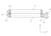
- the driving force from the main body drive motor is transmitted to the coupling 201 (driving force receiving part), and the driving force is transmitted to the toner supply roller 34 via the intermediate body 202 and the driving force transmission member 203 (the intermediate body 202 and the driving force transmission member 203 are the first driving force transmission part).
- the driving force of the toner supply roller 34 is transmitted to the developing roller 25 by the gears (204a to 204c) provided between the toner supply roller 34 and the developing roller 25, and the developing roller 25 rotates (the gear 204c is the second driving force transmission part, and the gear 204a is the third driving force transmission part).
- the driving force is transmitted to the idler gear 204b by the rotation of the gear 204c fixed to the toner supply roller 34, and the idler gear 204b rotates.
- the driving force is transmitted to the gear 204a fixed to the developing roller 25 by the rotation of the idler gear 204b, and the developing roller 25 rotates together with the gear 204a.
- the driving force from the device body 100a to the developing unit 4 is input from the longitudinal axis of the toner supply roller 34.
- the driving force from the device body 100a to the developing unit 4 were input from the longitudinal axis of the developing roller 25, the driving input positions to the cleaning unit 26 and the developing unit 4 would be close to each other due to the fact that the photosensitive drum 1 and the developing roller 25 are in contact with each other for development.
- the driving force to the developing unit 4 is input from the longitudinal axis of the toner supply roller 34, so the input position to the cleaning unit 26 and the driving force input position to the developing unit 4 can be spaced apart, which is more preferable when configuring the driving force input section of the device main body 100a.
- the driving force from the device main body 100a is transmitted to the developing roller 25 via the toner supply roller 34, and because it is necessary to go through multiple gears to drive the developing roller 25, the rotational stability of the developing roller 25 is inferior compared to a configuration in which the driving force is transmitted to the developing roller 25.
- the regulating force of the developing blade 35 may become unstable, making this a disadvantageous configuration in terms of regulating failure.
- the toner supply roller 34 and the developing roller 25 rotate in opposite directions at a peripheral speed difference in the nip portion N2, and this operation collects the remaining toner on the developing roller 25 while supplying toner to the developing roller 25.
- the radius of the toner supply roller is 3.3 mm and the radius of the developing roller is 3.0 mm, so that ⁇ 1.14.
- the toner supply roller 34 and the developing roller 25 are in contact with each other with a predetermined intrusion amount, i.e., the indentation amount ⁇ E by which the toner supply roller 34 is made concave by the developing roller 25.
- the toner supply roller 34 comprises a conductive support and a foam layer supported by the conductive support. Specifically, it has a core metal electrode with an outer diameter of ⁇ 5 (mm) as the conductive support, and a foamed urethane layer as a foam layer composed of open cells (open bubbles) in which the bubbles are connected to each other around it, and rotates in the direction of C in the figure.
- a foamed urethane layer as a foam layer composed of open cells (open bubbles) in which the bubbles are connected to each other around it, and rotates in the direction of C in the figure.
- the resistance of the toner supply roller 34 in this embodiment is 1 x 10 ⁇ 9 ( ⁇ ).
- the amount of penetration of the toner supply roller 34 into the developing roller 25, i.e., the amount of depression ⁇ E by which the toner supply roller 34 is made concave by the developing roller 25, was set to 1.0 mm.
- the toner supply roller 34 is brought into contact with an aluminum sleeve having a diameter of 30 mm so that the amount of penetration, described below, is 1.5 mm. By rotating this aluminum sleeve, the toner supply roller 34 is rotated at 30 rpm relative to the aluminum sleeve.
- a DC voltage of -50 V is applied to the developing roller 25.
- a 10 k ⁇ resistor is provided on the earth side, and the current is calculated by measuring the voltage across the resistor, and the resistance of the toner supply roller 34 is calculated.
- the surface cell diameter of the toner supply roller 34 is set to 50 ⁇ m to 1000 ⁇ m.
- cell diameter refers to the average diameter of foam cells in any cross section.
- the area of the largest foam cell is measured from an enlarged image of the cross section, and the maximum cell diameter is obtained by converting this area into a diameter equivalent to a perfect circle. Foam cells that are half or less of this maximum cell diameter are then eliminated as noise, and the average of the individual cell diameters calculated in the same manner from the remaining individual cell areas is used.
- the toner supplied to the surface of the developing roller 25 from the toner supply roller 34 is frictionally charged by the rubbing between the developing blade 35 and the developing roller 25, and the layer thickness is regulated while the toner is given an electric charge.
- the toner is then transported to the contact area (developing section) between the photosensitive drum 1 and the developing roller 25, and transferred to the light potential section. Residual toner remaining on the surface of the developing roller 25 returns to the developing container, is collected from the surface of the developing roller 25 by the toner supply roller 34, and is stored inside the toner supply roller 34.
- FIG. 6 is an enlarged schematic cross-sectional view of the inside of the developing chamber 31b, and shows the movement of toner transported from the toner transport member 36 shown in FIG. 2 to the toner supply roller 34.
- Some of the toner G transported to the top of the toner supply roller 34 by the toner transport member 36 is sucked into the toner supply roller 34 due to the restoration of the toner supply roller 34 downstream of the rotation of the nip portion N2 (F1), and is stored inside the toner supply roller 34 together with the remaining toner collected from the surface of the developing roller 25 and stored inside the toner supply roller 34. Then, due to the rotation of the toner supply roller 34 in the C direction, the toner is transported to the downstream side of the rotation of the toner supply roller 34 at the nip portion N2. At the downstream side of the rotation of the toner supply roller 34, the toner supply roller 34 comes into contact with the developing roller 25, causing the toner supply roller 34 to deform, causing the toner stored inside to be expelled (F2).
- the toner discharged from the toner supply roller 34 that does not reach the surface of the developing roller 25 is gradually transported by the propulsion force toward the developing opening (opening) caused by the ejection force from the toner supply roller 34, and is returned through the developing opening to the toner storage chamber 31a (F3).
- toner circulates smoothly between the developing chamber 31b and the toner storage chamber 31a, preventing toner deterioration. Even when images with low print coverage are output continuously, toner aggregation is prevented, allowing high-quality images to be output stably.
- This phenomenon is likely to occur, for example, when images with a low printing rate are continuously output in a low-temperature, low-humidity environment. This is because the residual toner collected from the developing roller 25 by the toner supply roller 34 accumulates in the developing chamber 31b. Because the residual toner collected from the developing roller 25 is charged, the toner particles tend to electrostatically clump together. This reduces the fluidity of the toner in the developing chamber 31b, making the flow of toner (F3) returning to the toner storage chamber 31a insufficient, and creating a state in which toner clumping is likely to occur in the areas below the toner supply roller 34 and the developing roller 25.
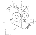
- the inner wall of the developing chamber 31b is set as follows relative to the toner supply roller 34. This is specifically explained in Figure 7.
- R1 and R2 in FIG. 7 indicate tangents (vertical lines) to the outer peripheral surface of toner supply roller 34 that extend in the vertical direction.
- Horizontal line H2 indicates a horizontal line that passes through the support end of development blade 35.
- At least a portion of the region between R1 and R2 of the inner wall of development chamber 31b is located vertically above horizontal line H2 (region 138 in the figure). This makes it possible to further reduce the amount of toner remaining in development chamber 31b that is not used for printing, and toner in development chamber 31b can be used efficiently.
- a toner-blowing prevention sheet 20 is provided as a developer contact sheet to prevent toner from leaking from the developing frame 31 that is in contact with the developing roller 25.
- the toner storage chamber 31a of the developing frame 31 is provided with a toner transport member 36 for stirring the stored toner and transporting the toner to the toner supply roller 34.
- the toner transport member 36 is composed of a stirring shaft 36a that can be rotated by a driving force from the device main body 100a, and a sheet member 36b that is attached to the stirring shaft 36a and rotates together with the stirring shaft 36a.
- the toner storage chamber 31a is provided with a restoration portion 31a2 downstream of the deformation portion 31a1 and upstream of the opening 31c during the rotation of the sheet member 36b.
- the restoration portion 31a2 is a portion for releasing the contact between the sheet member 36b and the inner wall of the toner storage chamber 31a.
- the restoration portion 31a2 is located above a horizontal plane that includes the rotation axis of the stirring member.
- the contact with the inner wall of the sheet member 36b is released at the restoration portion 31a2. Then, the sheet member 36b is released from the state in which it was deformed by the deformation portion 31a1 and is restored to its natural state (original shape) by its own elastic restoring force. Due to this change in shape of the sheet member 36b in the restoration direction, the toner carried and transported on the sheet member 36b flies against gravity toward the opening 31c. This opening 31c is located downstream of the restoration portion 31a2 in the rotation direction of the sheet member 36b. A part of the toner that flies toward the opening 31c is transported into the developing chamber 31b.
- the toner that does not reach the developing chamber 31b falls into the inside of the toner storage chamber 31a and remains at the bottom of the toner storage chamber 31a, and returns to its original state. By repeating this cycle, the toner is stirred and transported.
- the configuration with the deformation portion 31a1 and the restoration portion 31a2 is advantageous for increasing the efficiency of transporting toner to the developing chamber 31b, but it is a configuration that is likely to obstruct the flow of toner returning to the toner storage chamber (F3), and is therefore prone to regulation failure.
- the length of the rotation axis of the sheet member 36b in the natural state in the direction of the rotation radius is set to be longer than the distance from the rotation axis to the lower end of the developing opening in the same direction.
- the toner in this embodiment is a toner containing toner particles containing a binder resin, and hydrotalcite particles used as a microcarrier to enhance the negative charging characteristics of the toner particles.
- the hydrotalcite particles contain fluorine.
- Hydrotalcite particles have a high positive charging property, so they have a strong positive polarity.
- the charge amount can be adjusted so that they do not have a strong positive polarity.
- By making the hydrotalcite particles contain fluorine it is possible to prevent the hydrotalcite particles from being charged to a strong positive polarity, and therefore it is possible to prevent the toner from becoming a strong negative polarity.
- the percentage of strongly negative toner particles with a charge amount Q/M per unit weight of -25 ⁇ C/g or more was compared. It was confirmed that the percentage of strongly negative toner particles was reduced by approximately 23% for toner with fluorine-containing hydrotalcite added, compared to toner with non-fluorine-containing hydrotalcite added.
- the contact position of the development roller 25 with the development blade 35 must be set on the fixed end side in order to obtain the toner coat amount required to obtain the desired image density.
- toner regulated by the developing blade 35 is explained in FIG. 8 for both the case where a developing blade 35 with a "capture area J" on the leading edge is used, and the case where a developing blade 35 without a "capture area J" on the leading edge is used.
- Figure 8(a) shows the case where a developing blade 35 with a "capture area J" is used at the leading edge.
- the white circles in the figure represent toner, and the movement of the toner regulated by the developing blade 35 is indicated by arrow K1.
- a portion of the toner that has invaded close to the contact point D with the developing blade 35 due to the rotation of the developing roller 25 in the direction of arrow D1 is detached from the surface of the developing roller 25 by the regulating force of the developing blade 35.
- This regulated toner moves in a direction in which the toner powder pressure from behind is weaker, so that it moves back into the developing chamber 31b along the second surface 812 of the leading edge.
- good toner circulation can be created in the "capture area J" of the leading edge, and during this circulation, the charge held by the toner can be transferred by rubbing against each other.
- the "take-in area J" at the leading edge of the developing blade 35 has a point F on the developing blade 35 that is at least a distance from the developing roller 25 that is greater than the toner volume average particle diameter R, and the width d2 of the take-in area on the free end side of point F is greater than the toner volume average particle diameter R, meaning that one toner particle can exist in the "take-in area", which is thought to cause the toner circulation described above.
- the toner used in this embodiment has a volume average particle diameter of approximately 7.0 ⁇ m, and the leading edge shape of the developing blade is polished so that point F exists and d2 is greater than the toner volume average particle diameter R.
- the angle ⁇ between the developing blade 35 and the developing roller 25 at point F is preferable to set the angle ⁇ between the developing blade 35 and the developing roller 25 at point F to 45° or less, so that the direction of the arrow K1 is more opposite to the direction of movement of the developing roller 25, which causes the toner particles to rub against each other more frequently in the "take-in area J", making it easier to achieve the effect of transferring the charge held by the toner. More preferably, setting ⁇ to 25° or less makes it even easier to achieve the above effect.
- FIG. 8B shows a case where a developing blade 35 without a "capture area J" at the leading edge is used.
- a developing blade 35 in order to obtain a toner coat amount for obtaining a desired image density, it is necessary to set the contact point D of the developing roller 25 with respect to the developing blade 35 closer to the fixed end side compared to the developing blade 35 in FIG. 8A. By setting it in this way, a sufficient amount of toner can be taken into the regulating section.
- the toner regulated by the regulating force of the developing blade 35 is unlikely to move back into the developing chamber 31b due to the powder pressure of the toner transported from the rear by the rotation of the developing roller 25.
- toner with non-fluorine-containing hydrotalcite added when toner with non-fluorine-containing hydrotalcite added is used, the amount of toner with a strong negative polarity increases compared to toner with fluorine-containing hydrotalcite added, as described above.
- the regulating force of the development blade 35 weakens, and regulating failures are likely to occur, just like when toner with fluorine-containing hydrotalcite added is used.
- the capture angle ⁇ is set to be between 0° ⁇ ⁇ ⁇ 25°. This makes it possible to achieve a sharp charge distribution for the toner passing through the regulating portion of the development blade 35.
- the hydrotalcite particles used in the toner in this embodiment will be described in detail.
- the hydrotalcite particles contain fluorine.
- the presence or absence of fluorine in the hydrotalcite particles can be confirmed by STEM-EDS mapping analysis of the toner.
- the analysis conditions and the like are the methods described below.
- fluorine is present inside the hydrotalcite particles.
- the detection of fluorine inside the hydrotalcite particles by the above analysis indicates that fluorine is intercalated between the layers of the hydrotalcite particles.
- hydrotalcite particles prevents the hydrotalcite particles from being charged excessively positively, and allows the hydrotalcite particles to maintain an appropriate amount of positive charge.
- hydrotalcite particles can maintain an appropriate amount of positive charge is that the highly negative fluorine present inside the hydrotalcite particles can absorb the positive charge on the surface of the hydrotalcite particles into the interior of the particles and neutralize it. In other words, it is presumed that this is because excessive positive charging of the particle surface can be suppressed.
- fluorine into the interior of the hydrotalcite particles by introducing fluoride ions between the layers (intercalation) through anion exchange.
- the ratio F/Al (element ratio) of the atomic concentration of fluorine to aluminum in the hydrotalcite particles, obtained from main component mapping of the hydrotalcite particles by STEM-EDS mapping analysis of the toner is preferably 0.01 to 0.65, and more preferably 0.02 to 0.60.
- F/Al element ratio
- the surface charge distribution of the hydrotalcite particles can be made uniform, and the charge stability of the toner can be improved, resulting in a toner that is sharply negatively charged.
- F/Al 0.65 or less the surface charge of the hydrotalcite particles is prevented from being excessively neutralized, the time stability of the positive charge is improved, and the charge stability of the toner is improved. As a result, the charge of the toner is prevented from becoming strongly negative, and a toner with a sharp charge distribution of negative polarity can be obtained.
- the atomic concentration of fluorine in the hydrotalcite particles is not particularly limited, but is preferably 0.01 atomic % to 5.00 atomic %, more preferably 0.04 atomic % to 3.00 atomic %, and even more preferably 0.09 atomic % to 2.00 atomic %. Being in this range ensures that the hydrotalcite particles have an appropriate positive tendency and that the microcarrier properties are in an appropriate range.
- the hydrotalcite particles may be those represented by the following composition formula (1):
- M and A are represented in an ionic state.
- the M 2+ and M 3+ represent a divalent metal cation and a trivalent metal cation, respectively.
- M2 + is preferably a divalent cation of at least one metal selected from the group consisting of Mg, Zn, Ca, Ba, Ni, Sr, Cu, and Fe.
- M 3+ is preferably a trivalent cation of at least one metal selected from the group consisting of Al, B, Ga, Fe, Co, and In.
- a n- is an n-valent anion and includes at least F- .
- a n- may include CO 3 2- , OH- , Cl- , I- , Br- , SO 4 2- , HCO 3- , CH 3 COO- , NO 3- , and the like in addition to F- , and may include a plurality of different anions.
- the metal that becomes the divalent cation is preferably Mg (magnesium), and the metal that becomes the trivalent cation is preferably Al (aluminum).
- the hydrotalcite particles preferably contain aluminum that becomes the trivalent cation and magnesium that becomes the divalent cation.
- Specific composition formulas include Mg 2+ 8.6 Al 3+ 4 (OH) 25.2 F ⁇ 2 CO 3 2 ⁇ .mH 2 O and Mg 2+ 12 Al 3+ 4 (OH) 32 F ⁇ 2 CO 3 2 ⁇ .mH 2 O.
- the hydrotalcite particles contain aluminum, which is a trivalent cation, and magnesium, which is a divalent cation, it is preferable that the ratio of the atomic concentration (atomic %) of magnesium to the atomic concentration (atomic %) of aluminum (Mg/Al) is 1.50 to 4.00.
- the hydrotalcite particles have water in their molecules, and it is more preferable that in formula (1), 0.1 ⁇ m ⁇ 0.6.
- the number average particle size H3 of the primary particles of the hydrotalcite particles is preferably 40 nm to 1100 nm, and more preferably 60 nm to 1000 nm.
- the number-average particle diameter of the hydrotalcite particles is within the above range, the charge rise property of the toner becomes good, and the charge distribution of the toner becomes easy to be sharpened.
- the particle size can be measured by known means such as a scanning electron microscope.
- the particle size can also be controlled by controlling the conditions of the reaction process, the grinding process, the centrifugation process, the classification process, and the sieving process in the manufacturing process of the hydrotalcite particles.
- the hydrotalcite particles may be hydrophobized with a surface treatment agent.
- surface treatment agents that can be used include higher fatty acids, coupling agents, esters, and oils such as silicone oil. Of these, higher fatty acids are preferably used, and specific examples include stearic acid, oleic acid, and lauric acid.
- the adhesion rate of the hydrotalcite particles to the toner particles is preferably 10% to 95%. More preferably, it is 40% to 95%, and even more preferably, it is 50% to 70%. Within the above range, the above effects are easily obtained.
- the adhesion rate can be controlled by changing the external addition conditions using a known external addition method.
- the area ratio of the hydrotalcite particles to the toner particles in the EDS measurement field of view, as measured by STEM-EDS mapping analysis of the toner, is preferably 0.07% to 0.54%. Furthermore, it is more preferable that it is 0.25% to 0.50%, and even more preferable that it is 0.35% to 0.45%. If it is within the above range, the above effect is easily obtained.
- the above area ratio can be controlled by changing the input amount of the hydrotalcite particles.
- Examples of the wet production method include a suspension polymerization method, a dissolution suspension method, an emulsion polymerization aggregation method, and an emulsion aggregation method (the difference between emulsion polymerization aggregation and emulsion aggregation), and the emulsion aggregation method is more preferred from the viewpoint of dispersing the polyvalent metal element on the surface of the toner particles and inside the toner particles.
- a dispersion of each material such as binder resin particles and colorant
- a dispersion stabilizer as necessary.
- an aggregating agent is added to aggregate the particles until they reach the desired toner particle size, and then, or simultaneously with the aggregation, the resin particles are fused together. If necessary, the shape is controlled by heat to form toner particles.
- the binder resin microparticles can be composite particles formed of multiple layers, consisting of two or more layers of resins with different compositions.
- they can be manufactured by emulsion polymerization, mini-emulsion polymerization, phase inversion emulsification, or a combination of several manufacturing methods.
- the internal additive may be contained in the resin microparticles, or a dispersion of internal additive microparticles consisting only of the internal additive may be prepared separately, and the internal additive microparticles may be aggregated together with the resin microparticles when they are aggregated.
- resin microparticles with different compositions can be added at different times during aggregation and aggregated to create toner particles with layer configurations of different compositions.
- an inorganic salt or a divalent or higher inorganic metal salt can be suitably used.
- an inorganic metal salt is preferred because it is easy to control the flocculation property and the toner charge property by ionizing a polyvalent metal element in an aqueous medium.
- preferred inorganic metal salts include metal salts such as calcium chloride, calcium nitrate, barium chloride, magnesium chloride, zinc chloride, iron chloride, aluminum chloride, and aluminum sulfate, as well as inorganic metal salt polymers such as polyiron chloride, polyaluminum chloride, polyaluminum hydroxide, and calcium polysulfide.
- metal salts such as calcium chloride, calcium nitrate, barium chloride, magnesium chloride, zinc chloride, iron chloride, aluminum chloride, and aluminum sulfate
- inorganic metal salt polymers such as polyiron chloride, polyaluminum chloride, polyaluminum hydroxide, and calcium polysulfide.
- aluminum salts and their polymers are particularly preferred.
- the valence of the inorganic metal salt is preferably divalent rather than monovalent, and more preferably trivalent or more than divalent, and even if the valence is the same, inorganic metal salt polymers are more suitable.
- the volume-based median diameter of the toner particles is 3.0 ⁇ m to 10.0 ⁇ m.
- hydrotalcite particles can be identified by a combination of shape observation using a scanning electron microscope (SEM) and elemental analysis using energy dispersive X-ray analysis (EDS).
- SEM scanning electron microscope
- EDS energy dispersive X-ray analysis
- the toner is observed at a maximum magnification of 50,000 times.
- the focus is set on the surface of the toner particles, and the external additive to be identified is observed.
- An EDS analysis is performed on the external additive to be identified, and the hydrotalcite particles can be identified from the type of element peak.
- a sample of the hydrotalcite particles inferred from the EDS analysis is prepared separately, and shape observation by SEM and EDS analysis are performed.
- the analysis results of the sample are compared to the analysis results of the particles to be identified to see if they match, and it is determined whether or not they are hydrotalcite particles.
- the ratio of each element in the hydrotalcite particles is measured by EDS mapping measurement of the toner using a scanning transmission electron microscope (STEM).
- STEM scanning transmission electron microscope
- spectrum data is obtained for each pixel in the analysis area.
- the observation sample is prepared according to the following procedure. 0.5 g of the toner is weighed out, and placed in a cylindrical mold with a diameter of 8 mm and left to stand for 2 minutes under a load of 40 kN using a Newton press to prepare a cylindrical toner pellet with a diameter of 8 mm and a thickness of about 1 mm. A thin section with a thickness of 200 nm is prepared from the toner pellet using an ultramicrotome (Leica, FC7).
- the STEM-EDS analysis is carried out using the following apparatus and conditions. Scanning transmission electron microscope: JEM-2800 manufactured by JEOL Ltd. EDS detector: JED-2300T Dry SD100GV detector (detection element area: 100 mm 2 ) manufactured by JEOL Ltd. EDS analyzer: NORAN manufactured by Thermo Fisher Scientific System 7 [STEM-EDS conditions] ⁇ STEM acceleration voltage: 200 kV Magnification: 20,000x Probe size: 1 nm STEM image size: 1024 x 1024 pixels (EDS element mapping images are obtained at the same position.) EDS mapping size: 256 x 256 pixels, Dwell Time: 30 ⁇ s, number of integrations: 100 frames
- the above-mentioned STEM-EDS analysis device is used to obtain EDS mapping.
- the collected spectral mapping data is subjected to multivariate analysis using the COMPASS (PCA) mode in the measurement command of the above-mentioned NORAN System 7, and a principal component map image is extracted.
- PCA COMPASS
- this operation calculates the area ratio of each extracted principal component in the EDS measurement field of view. Quantitative analysis is then performed using the Cliff-Lorimer method on the EDS spectrum of each principal component mapping obtained.
- FIG. 9(a) A schematic diagram of the line analysis is shown in FIG. 9(a).
- a line analysis is performed in the normal direction to the outer periphery of the hydrotalcite particle 93, i.e., in the direction 95.
- the area in which hydrotalcite particles are present in the acquired STEM image is selected with a rectangular selection tool, and line analysis is performed under the following conditions.
- Line analysis conditions STEM magnification: 800,000 times; Line length: 200 nm Line width: 30 nm Number of line divisions: 100 points (intensity measurement every 2 nm)
- the criteria for determining that the element is contained inside the hydrotalcite particles are as follows: When the element peak intensity of fluorine or aluminum is 1.5 times or more the background intensity in the EDS spectrum of the hydrotalcite particles. When the element peak intensity of fluorine or aluminum at both ends of the hydrotalcite particle (points a and b in Figure 9(a)) in the line analysis does not exceed 3.0 times the peak intensity at point c. When all of the above conditions are met, the element is determined to be contained inside the hydrotalcite particles. Note that point c is the midpoint of line segment ab (i.e., the midpoint of the above-mentioned both ends).
- ⁇ Method of calculating fluorine atom number concentration in hydrotalcite particles The atomic concentration of fluorine in the hydrotalcite particles is calculated based on the mapping data obtained by the STEM-EDS mapping analysis using the above-mentioned method.
- the atomic concentration of fluorine (element amount) in the hydrotalcite particles is quantified in the main component map image of the hydrotalcite particles extracted using the above-mentioned method.
- mapping data is obtained from multiple fields of view, and the arithmetic average for 100 or more hydrotalcite particles is taken as the fluorine atomic concentration in the hydrotalcite particles.
- the number average particle size S3 of the primary particles of the hydrotalcite particles is measured by combining a scanning electron microscope "S-4800" (product name; manufactured by Hitachi, Ltd.) and elemental analysis by energy dispersive X-ray analysis (EDS).
- S-4800 scanning electron microscope
- EDS energy dispersive X-ray analysis
- a toner to which hydrotalcite particles have been externally added as an external additive is observed, and the hydrotalcite particles are photographed in a field of view magnified up to 200,000 times. From the photographed image, hydrotalcite particles are selected, and the major axis of the primary particles of 100 hydrotalcite particles is measured at random to determine the number average particle size of the hydrotalcite particles.
- the observation magnification is appropriately adjusted depending on the size of the external additive.
- Toner before washing Various toners prepared in the examples described later are used as they are.
- Toner after washing 160 g of sucrose (Kishida Chemical) is added to 100 mL of ion-exchanged water, and dissolved in a hot water bath to prepare a concentrated sucrose solution.
- Contaminon N a 10% aqueous solution of a neutral detergent for cleaning precision measuring instruments, pH 7, consisting of a nonionic surfactant, an anionic surfactant, and an organic builder, manufactured by Wako Pure Chemical Industries, Ltd.
- the SEM/EDS equipment and observation conditions are as follows.
- ⁇ Production Example of Toner Particles> ⁇ Preparation of aqueous dispersion medium> The above aqueous solution was prepared and kept at 60° C. with high speed stirring to prepare an aqueous sodium phosphate solution. Water 17.1 parts Calcium chloride 2.4 parts After the above aqueous solution was prepared, it was added to the above aqueous sodium phosphate solution and stirred at high speed to prepare an aqueous dispersion medium containing calcium phosphate fine particles.
- ⁇ Washing, drying, and classification processes 10% hydrochloric acid was added to the above polymer particle dispersion to dissolve the calcium phosphate particle dispersant, which was then filtered, washed, dried, and classified using an air classifier to obtain toner particles with a weight average particle size of 5.8 ⁇ m.
- hydrotalcite particles 2 The hydrotalcite (primary particle number average particle size: 240 nm) used in the preparation of hydrotalcite particles 1 was designated as hydrotalcite particles 2. In line analysis in the STEM-EDS mapping analysis, the presence of fluorine inside hydrotalcite particles 2 could not be confirmed.
- the adhesion rate of the hydrotalcite particles to the toner particles was 30%.
- Toner 2 was obtained in the same manner as in the production example of toner 1, except that the hydrotalcite particles used in the production example of toner 1 were changed to hydrotalcite particles 2.
- Toner 3 was obtained in the same manner as in Toner 1 Production Example, except that the hydrotalcite particles used in Toner 1 Production Example were changed to Hydrotalcite Particles 3.
- a reflection densitometer (Model TC-MOR-45, manufactured by Tokyo Denshoku Co., Ltd., using a green filter) was used to measure the reflectance (%) in order to measure the fog density caused by poor regulation.
- Fog measurements were performed by attaching Post-it notes or the like to part of the paper to be printed, forming a blank image, and outputting the paper.
- Fog measurements were performed using the reflectance of the part of the output paper from which the Post-it notes were removed as the reference reflectance of the paper itself. Reflectance differs depending on the part measured, and the difference between the measured value of the part with the smallest value and the measured value (reference reflectance) of the part with the Post-it note attached was measured as the fog value. The smaller the measured fog value, the less fog there is, and the better the image quality.
- a developing blade 35 in which a "capture area J" is formed by polishing the leading edge portion is used as the developing blade 35, but the present invention is not limited to this.
- a similar effect can be obtained by using a developing blade 35 whose leading edge is bent at a predetermined radius of curvature.
- a point F on the developing blade 35 exists in the "capture area J" of the leading edge of the developing blade 35, which is farther away from the developing roller 25 than the volume average particle size R of the toner, and the width d2 of the capture area on the free end side of point F is larger than the volume average particle size R of the toner, so it is believed that a similar effect can be obtained.
Landscapes
- Physics & Mathematics (AREA)
- General Physics & Mathematics (AREA)
- Engineering & Computer Science (AREA)
- Computer Vision & Pattern Recognition (AREA)
- Dry Development In Electrophotography (AREA)
- Developing Agents For Electrophotography (AREA)
Abstract
感光ドラム、現像ローラ、供給ローラ、現像室、弾性ブレードと支持部を含む現像ブレード、粒径Rのトナーの収容部を有するカートリッジであり、収容部と現像室は連通し、現像ブレードと現像ローラの接触箇所は現像ローラの回転軸中心を通る水平線より下方であり、トナー外添剤のハイドロタルサイト粒子内部にフッ素が存在し、弾性ブレードと現像ローラのニップにおいて現像ローラ回転方向上流側の端部を点D、弾性ブレードの最も自由端側を点B、点Bからの垂線と現像ローラが交わる点を点E、現像ローラ表面からの距離がRとなる弾性ブレード表面上の点のうち最も自由端側の点を点F、現像ローラ表面からの距離がRとなる直線BE上の点をGとしたとき、GFの距離がR以上であるカートリッジを用いる。
Description
本発明は、プロセスカートリッジに関する。
電子写真画像形成方式(電子写真プロセス)を用いたプリンタ等の画像形成装置では、像担持体としての電子写真感光体(以下、「感光体」という。)を一様に帯電させ、帯電した感光体を選択的に露光することによって、感光体上に静電像を形成する。感光体上に形成された静電像は、現像剤としてのトナーでトナー像として顕像化される。そして、感光体上に形成されたトナー像を、記録用紙、プラスチックシート等の記録材に転写し、更に記録材上に転写されたトナー像に熱や圧力を加えることでトナー像を記録材に定着させることで画像記録を行う。
このような画像形成装置は、一般に、現像剤の補給や各種のプロセス手段のメンテナンスを必要とする。この現像剤の補給作業や各種のプロセス手段のメンテナンスを容易にするために、感光体、帯電手段、現像手段、クリーニング手段等を枠体内にまとめてカートリッジ化し、画像形成装置本体に着脱可能なプロセスカートリッジとすることが実用化されている。プロセスカートリッジ方式によれば、ユーザビリティーに優れた画像形成装置を提供することができる。
又、近年、複数色の現像剤を用いてカラー画像を形成するカラー画像形成装置が普及してきている。カラー画像形成装置としては、複数色の現像剤を用いた画像形成動作のそれぞれに対応する感光体を、トナー像が転写される被転写体の表面移動方向に沿って一列に配置した、所謂、インライン方式の画像形成装置が知られている。インライン方式のカラー画像形成装置には、複数の感光体が鉛直方向(重力方向)と交差する方向(例えば水平方向)に一列に配置されたものがある。インライン方式は、画像形成速度の高速化やマルチファンクションプリンタへの展開などの要望に対応し易いなどの点で好ましい画像形成方式である。
又、画像形成装置として、感光体を、被転写体としての中間転写体、又は、被転写体としての記録材を搬送する記録材担持体の下方に配置したものがある(特開2011-253203号公報)。
感光体を中間転写体や記録材担持体の下方に配置する場合、画像形成装置本体内において中間転写体や記録材担持体を間に挟む態様で、例えば定着装置と現像装置(或いは、露光装置)とを離れた位置に配置することができる。そのため、現像装置(或いは、露光装置)が定着装置の熱の影響を受け難いなどの利点がある。
本発明の目的は、従来のカートリッジをさらに発展させたカートリッジを提供することである。
本発明は以下の構成である。すなわち、
画像形成装置に装着可能なプロセスカートリッジであって、
像担持体である感光ドラムと、該感光ドラムにトナー像を現像する為の現像ローラと、
該現像ローラにトナーを供給する為の供給ローラと、
該現像ローラと該供給ローラを軸支する為の支持部を有する現像室と、
該現像ローラ上のトナーを層厚規制する為の現像ブレードと、
体積平均粒径Rのトナー粒子及び外添剤を有するトナーと、
該トナーを収容する為のトナー収容部とを有し、
前記トナー収容部は、前記現像室と連通口を介して連通するように構成されており、
現像ローラ表面の移動方向は、前記供給ローラとの接触位置において、該供給ローラの表面の移動方向と逆向きとなるように構成されており、
前記画像形成装置の装置本体に装着された装着状態での、前記現像ローラの回転軸に垂直な面におけるプロセスカートリッジ断面において、前記現像ローラの回転軸中心を通る水平線H1より、前記現像ブレードが現像ローラに接触する箇所は、鉛直方向下方であり、
駆動力受け部を有し、
該駆動力受け部からの駆動力を前記供給ローラへ伝達するための第1駆動力伝達部と、
前記供給ローラに設けられ、前記第1駆動力伝達部で受けた駆動力を前記現像ローラへ伝達するための第2駆動力伝達部と、
前記現像ローラに設けられ、前記第2駆動力伝達部からの駆動力を前記現像ローラへ伝達する第3駆動力伝達部と、
を有するプロセスカートリッジであって、
前記トナーは、前記外添剤としてのハイドロタルサイト粒子を有し、
前記トナーのSTEM-EDSマッピング分析におけるライン分析において、前記ハイドロタルサイト粒子の内部にフッ素が存在し、
前記現像ブレードは板状の金属製の弾性ブレードと、該弾性ブレードを支持する為のブレード支持部からなり、
前記現像ローラの回転軸に垂直な面におけるプロセスカートリッジ断面において、
前記弾性ブレードは現像ローラとニップN1を形成して当接しており、
前記弾性ブレード上のニップN1において現像ローラ回転方向上流側の端部の点を点Dとし、
前記弾性ブレードで最も自由端側であり、最も前記現像ローラ表面に近い点を点Bとし、
点Bから前記現像ローラ表面におろした垂線と前記現像ローラ表面が交わる点をEとし、
前記現像ローラ表面からの距離がRとなる前記弾性ブレード表面上の点で、最も前記弾性ブレードの自由端側にある点Fが存在し、
前記現像ローラ表面からの距離がRとなる直線BE上の点をGとしたとき、GFの距離がR以上である
ことを特徴とするプロセスカートリッジである。
本発明はまた、以下の構成である。すなわち、
画像形成装置に装着可能なプロセスカートリッジであって、
像担持体である感光ドラムと、該感光ドラムにトナー像を現像する為の現像ローラと、
該現像ローラにトナーを供給する為の供給ローラと、
該現像ローラと該供給ローラを軸支する為の支持部を有する現像室と、
該現像ローラ上のトナーを層厚規制する為の現像ブレードと、
体積平均粒径Rのトナー粒子及び外添剤を有するトナーと、
該トナーを収容する為のトナー収容部とを有し、
前記トナー収容部は、前記現像室と連通口を介して連通するように構成されており、
現像ローラ表面の移動方向は、前記供給ローラとの接触位置において、
該供給ローラの表面の移動方向と逆向きとなるように構成されており、
前記現像ブレードは板状の金属製の弾性ブレードと、該弾性ブレードを支持する為のブレード支持部からなり、
前記現像ローラの回転軸に垂直な面におけるプロセスカートリッジ断面において、
前記供給ローラと前記現像ローラの回転中心を結ぶ直線Aが水平から約9.85°傾いており、前記供給ローラの回転軸中心が前記現像ローラの回転軸中心よりも下側であって前記感光ドラムの回転軸中心が直線Aよりも上側になるような姿勢において、前記弾性ブレードが前記現像ローラに接触する箇所は、該現像ローラの回転軸中心よりも下方であり、
駆動力受け部を有し、
該駆動力受け部からの駆動力を前記供給ローラへ伝達するための第1駆動力伝達部と、
前記供給ローラに設けられ、前記第1駆動力伝達部で受けた駆動力を前記現像ローラへ伝達するための第2駆動力伝達部と、
前記現像ローラに設けられ、前記第2駆動力伝達部からの駆動力を前記現像ローラへ伝達する第3駆動力伝達部を有する
プロセスカートリッジであって、
前記トナーは、前記外添剤としてのハイドロタルサイト粒子を有し、
前記トナーのSTEM-EDSマッピング分析におけるライン分析において、前記ハイドロタルサイト粒子の内部にフッ素が存在し、
前記現像ローラの回転軸に垂直な面におけるプロセスカートリッジ断面において、
前記弾性ブレードは現像ローラとニップN1を形成して当接しており、
前記弾性ブレード上のニップN1において現像ローラ回転方向上流側の端部の点を点Dとし、
前記弾性ブレードで最も自由端側であり、最も前記現像ローラ表面に近い点を点Bとし、
点Bから前記現像ローラ表面におろした垂線と前記現像ローラ表面が交わる点をEとし、
前記現像ローラ表面からの距離がRとなる前記弾性ブレード表面上の点で、最も前記弾性ブレードの自由端側にある点Fが存在し、
前記現像ローラ表面からの距離がRとなる直線BE上の点をGとしたとき、GFの距離がR以上である
ことを特徴とするプロセスカートリッジである。
画像形成装置に装着可能なプロセスカートリッジであって、
像担持体である感光ドラムと、該感光ドラムにトナー像を現像する為の現像ローラと、
該現像ローラにトナーを供給する為の供給ローラと、
該現像ローラと該供給ローラを軸支する為の支持部を有する現像室と、
該現像ローラ上のトナーを層厚規制する為の現像ブレードと、
体積平均粒径Rのトナー粒子及び外添剤を有するトナーと、
該トナーを収容する為のトナー収容部とを有し、
前記トナー収容部は、前記現像室と連通口を介して連通するように構成されており、
現像ローラ表面の移動方向は、前記供給ローラとの接触位置において、該供給ローラの表面の移動方向と逆向きとなるように構成されており、
前記画像形成装置の装置本体に装着された装着状態での、前記現像ローラの回転軸に垂直な面におけるプロセスカートリッジ断面において、前記現像ローラの回転軸中心を通る水平線H1より、前記現像ブレードが現像ローラに接触する箇所は、鉛直方向下方であり、
駆動力受け部を有し、
該駆動力受け部からの駆動力を前記供給ローラへ伝達するための第1駆動力伝達部と、
前記供給ローラに設けられ、前記第1駆動力伝達部で受けた駆動力を前記現像ローラへ伝達するための第2駆動力伝達部と、
前記現像ローラに設けられ、前記第2駆動力伝達部からの駆動力を前記現像ローラへ伝達する第3駆動力伝達部と、
を有するプロセスカートリッジであって、
前記トナーは、前記外添剤としてのハイドロタルサイト粒子を有し、
前記トナーのSTEM-EDSマッピング分析におけるライン分析において、前記ハイドロタルサイト粒子の内部にフッ素が存在し、
前記現像ブレードは板状の金属製の弾性ブレードと、該弾性ブレードを支持する為のブレード支持部からなり、
前記現像ローラの回転軸に垂直な面におけるプロセスカートリッジ断面において、
前記弾性ブレードは現像ローラとニップN1を形成して当接しており、
前記弾性ブレード上のニップN1において現像ローラ回転方向上流側の端部の点を点Dとし、
前記弾性ブレードで最も自由端側であり、最も前記現像ローラ表面に近い点を点Bとし、
点Bから前記現像ローラ表面におろした垂線と前記現像ローラ表面が交わる点をEとし、
前記現像ローラ表面からの距離がRとなる前記弾性ブレード表面上の点で、最も前記弾性ブレードの自由端側にある点Fが存在し、
前記現像ローラ表面からの距離がRとなる直線BE上の点をGとしたとき、GFの距離がR以上である
ことを特徴とするプロセスカートリッジである。
本発明はまた、以下の構成である。すなわち、
画像形成装置に装着可能なプロセスカートリッジであって、
像担持体である感光ドラムと、該感光ドラムにトナー像を現像する為の現像ローラと、
該現像ローラにトナーを供給する為の供給ローラと、
該現像ローラと該供給ローラを軸支する為の支持部を有する現像室と、
該現像ローラ上のトナーを層厚規制する為の現像ブレードと、
体積平均粒径Rのトナー粒子及び外添剤を有するトナーと、
該トナーを収容する為のトナー収容部とを有し、
前記トナー収容部は、前記現像室と連通口を介して連通するように構成されており、
現像ローラ表面の移動方向は、前記供給ローラとの接触位置において、
該供給ローラの表面の移動方向と逆向きとなるように構成されており、
前記現像ブレードは板状の金属製の弾性ブレードと、該弾性ブレードを支持する為のブレード支持部からなり、
前記現像ローラの回転軸に垂直な面におけるプロセスカートリッジ断面において、
前記供給ローラと前記現像ローラの回転中心を結ぶ直線Aが水平から約9.85°傾いており、前記供給ローラの回転軸中心が前記現像ローラの回転軸中心よりも下側であって前記感光ドラムの回転軸中心が直線Aよりも上側になるような姿勢において、前記弾性ブレードが前記現像ローラに接触する箇所は、該現像ローラの回転軸中心よりも下方であり、
駆動力受け部を有し、
該駆動力受け部からの駆動力を前記供給ローラへ伝達するための第1駆動力伝達部と、
前記供給ローラに設けられ、前記第1駆動力伝達部で受けた駆動力を前記現像ローラへ伝達するための第2駆動力伝達部と、
前記現像ローラに設けられ、前記第2駆動力伝達部からの駆動力を前記現像ローラへ伝達する第3駆動力伝達部を有する
プロセスカートリッジであって、
前記トナーは、前記外添剤としてのハイドロタルサイト粒子を有し、
前記トナーのSTEM-EDSマッピング分析におけるライン分析において、前記ハイドロタルサイト粒子の内部にフッ素が存在し、
前記現像ローラの回転軸に垂直な面におけるプロセスカートリッジ断面において、
前記弾性ブレードは現像ローラとニップN1を形成して当接しており、
前記弾性ブレード上のニップN1において現像ローラ回転方向上流側の端部の点を点Dとし、
前記弾性ブレードで最も自由端側であり、最も前記現像ローラ表面に近い点を点Bとし、
点Bから前記現像ローラ表面におろした垂線と前記現像ローラ表面が交わる点をEとし、
前記現像ローラ表面からの距離がRとなる前記弾性ブレード表面上の点で、最も前記弾性ブレードの自由端側にある点Fが存在し、
前記現像ローラ表面からの距離がRとなる直線BE上の点をGとしたとき、GFの距離がR以上である
ことを特徴とするプロセスカートリッジである。
以上説明したように、本発明によれば、従来のカートリッジをさらに発展させたカートリッジを提供することができる。
以下、本発明に係る現像装置、プロセスカートリッジ及び画像形成装置を図面に則して更に詳しく説明する。ただし、この実施の形態に記載されている構成部品の寸法、材質、形状、その相対配置などは、特に記載がない限りは、この発明の範囲をそれらのみに限定する趣旨のものではない。また、以下の説明で一度説明した部材についての材質、形状などは、特に改めて記載しない限り、後の説明においても初めの説明と同様のものである。特に図示あるいは記述をしない構成や工程には、当該技術分野の周知技術または公知技術を適用することが可能である。また、重複する説明は省略する場合がある。
<実施例>
[画像形成装置]
図1は、本実施例の画像形成装置100を実際に使用する時と同様に、水平面に静置した姿勢での概略構成を示す図である。本実施例の画像形成装置100は、インライン方式で、中間転写方式を採用したフルカラーレーザープリンタである。図1に示すように、着脱可能な4個のプロセスカートリッジ70(70Y,70M,70C,70K)が装着部材(不図示)によって装着されている。またプロセスカートリッジ70の画像形成装置100の装着方向上流側を前側面側、装着方向下流側を奥側面側と定義する。
[画像形成装置]
図1は、本実施例の画像形成装置100を実際に使用する時と同様に、水平面に静置した姿勢での概略構成を示す図である。本実施例の画像形成装置100は、インライン方式で、中間転写方式を採用したフルカラーレーザープリンタである。図1に示すように、着脱可能な4個のプロセスカートリッジ70(70Y,70M,70C,70K)が装着部材(不図示)によって装着されている。またプロセスカートリッジ70の画像形成装置100の装着方向上流側を前側面側、装着方向下流側を奥側面側と定義する。
各プロセスカートリッジ70には、電子写真感光ドラム(以下、感光ドラムという)1(1a,1b,1c,1d)が配置されている。また、各プロセスカートリッジ70において感光ドラム1の周囲には、帯電ローラ2(2a,2b,2c,2d)、現像ローラ25(25a,25b,25c,25d)、クリーニング部材6(6a,6b,6c,6d)等のプロセス手段が一体的に配置されている。帯電ローラ2は、感光ドラム1の表面を一様に帯電させるものである。本実施例では負極性に帯電させる。現像ローラ25は、感光ドラム1に形成した潜像を現像剤(以下、トナー)によって現像して可視像化するものである。本実施例のトナーの正規極性は負極性である。そして、クリーニング部材6は、感光ドラム1に形成したトナー像を記録媒体に転写した後に、感光ドラム1に残留したトナーを除去するものである。感光ドラム1、帯電ローラ2、現像ローラ25、クリーニング部材6のより細かな構成や位置関係については、図2を参照しながら後述する。
また、プロセスカートリッジ70の重力方向における下方には、画像情報に基づいて感光ドラム1に選択的な露光を行い、感光ドラム1に潜像を形成するためのスキャナユニット3が設けられている。
装置本体100aの下部には記録媒体Sを収納したカセット17が装着されている。そして、記録媒体Sが2次転写ローラ69、定着部74を通過して装置本体100aの上方へ搬送されるように記録媒体搬送手段が設けられている。また、プロセスカートリッジ70(70Y,70M,70C,70K)の上方には各感光ドラム1(1a、1b、1c、1d)上に形成したトナー像を転写させるための中間転写手段としての中間転写ユニット5が設けられている。中間転写ユニット5には駆動ローラ56、従動ローラ57、各色の感光ドラム1に対向する位置に1次転写ローラ58(58a、58b、58c、58d)、2次転写ローラ69に対向する位置に対向ローラ59を有し、転写ベルト50が掛け渡されている。そして、転写ベルト50はすべての感光ドラム1に対向し、且つ接するように循環移動し、1次転写ローラ58(58a、58b、58c、58d)に電圧を印加することにより、感光ドラム1から転写ベルト50上に一次転写を行う。そして、転写ベルト50内に配置された対向ローラ59と2次転写ローラ69への電圧印加により、転写ベルト50のトナーを記録媒体Sに転写する。
画像形成に際しては、各感光ドラム1を回転させ、帯電ローラ2によって一様に帯電させた感光ドラム1にスキャナユニット3から選択的な露光を行う。これによって、感光ドラム1に静電潜像を形成する。その潜像を現像ローラ25によって現像する。これによって、各感光ドラム1に各色トナー像を形成する。この画像形成と同期して、レジストローラ対55が、記録媒体Sを対向ローラ59と2次転写ローラ69とが転写ベルト50を介在させて当接している2次転写位置に搬送する。そして、2次転写ローラ69へ転写バイアス電圧を印加することで、転写ベルト50上の各色トナー像を記録媒体Sに2次転写する。これによって、記録媒体Sにカラー画像を形成する。カラー画像が形成された記録媒体Sは、定着部74によって加熱、加圧されてトナー像が定着される。その後、記録媒体Sは、排出ローラ72によって排出部75に排出される。尚、定着部74は、装置本体100aの上部に配置されている。
[プロセスカートリッジ]
次に本発明を実施したプロセスカートリッジ70について、図2を用いて説明する。図2は、トナーを収容したプロセスカートリッジ70を、画像形成装置100の装着した状態の姿勢における主断面である。尚、イエロー色のトナーを収納したカートリッジ70Y、マゼンタ色のトナーを収納したカートリッジ70M、シアン色のトナーを収納したカートリッジ70C、ブラック色のトナーを収納したカートリッジ70Kは同一構成である。
次に本発明を実施したプロセスカートリッジ70について、図2を用いて説明する。図2は、トナーを収容したプロセスカートリッジ70を、画像形成装置100の装着した状態の姿勢における主断面である。尚、イエロー色のトナーを収納したカートリッジ70Y、マゼンタ色のトナーを収納したカートリッジ70M、シアン色のトナーを収納したカートリッジ70C、ブラック色のトナーを収納したカートリッジ70Kは同一構成である。
プロセスカートリッジ70は、クリーニングユニット26と、現像ユニット4と、を有する。クリーニングユニット26は、感光ドラム1と、帯電ローラ2、及びクリーニング部材6を備えている。そして、現像ユニット4は、現像ローラ25を備えている。
感光ドラム1の周上には、前述した通り帯電ローラ2、クリーニング部材6が配置されている。クリーニング部材6はゴムブレードで形成された弾性部材7とクリーニング支持部材8から構成されている。ゴムブレード製の弾性部材7の先端部は感光ドラム1の回転方向に対してカウンター方向に当接させて配設してある。そしてクリーニング部材6によって感光ドラム1表面から除去された残留トナーは除去トナー室27に落下する。
クリーニングユニット26に駆動源である本体駆動モータ(不図示)の駆動力を伝達することにより、感光ドラム1を画像形成動作に応じて回転駆動させる。このとき、感光ドラム1の長手端部に固定されたドラムカップリングと、感光ドラム1の長手軸線上に存在する本体側カップリングが係合することで、駆動力が感光ドラム1に入力される。帯電ローラ2は、帯電ローラ軸受を介し、クリーニングユニット26に回転可能に取り付けられており、帯電ローラ加圧部材により感光ドラム1に向かって加圧され、感光ドラム1に従動回転する。
現像ユニット4は、感光ドラム1と接触して回転する現像ローラ25と、現像ローラ25を支持する現像枠体31とから構成される。現像枠体31は、現像室31bとトナー収容室31a(トナー収容部)で構成される。
現像ローラ25の周上には、現像ローラ25に接触して矢印C方向に回転するトナー供給ローラ34と、現像ローラ25上のトナー層を規制するための現像ブレード35が配置されている。本実施例における現像ローラ25の外径は12mm、トナー供給ローラ34の外径は13.2mmである。プロセスカートリッジ70を、画像形成装置100に装着した状態の姿勢において、現像ローラ25の回転中心25eとトナー供給ローラ34の回転中心34eを結ぶ直線Aと、水平線Hとのなす角度αは、9.85度である。ただし角度αはこれに限定されない。
現像ユニット4にも、クリーニングユニットの駆動源とは別の本体駆動モータ(不図示)の駆動力を伝達することにより、現像ローラ25ならびにトナー供給ローラ34を画像形成動作に応じて回転駆動させる。駆動力の入力方法は、クリーニングユニット26と同様にカップリングを介しての駆動入力であり、詳細は後述する。カップリングでの駆動入力方法は、ギアを介する駆動入力に比べ、回転安定性の観点で好ましい。
現像ローラ25は、金属製の芯金の周囲に、弾性層としての所定の体積抵抗を有する導電性弾性ゴム層が設けられ構成された、弾性体ローラである。現像ローラ25は基層と表層からなる。基層にはシリコーンゴムを用い、表層にはウレタンゴムを用い、表層のウレタンゴム中にはウレタンビーズの粒子を分散させ、所望の粗さを設定している。現像ローラ25と感光ドラム1とは、対向部(接触部)において互いの表面が同方向(本実施例では下から上に向かう方向)に移動するようにそれぞれ回転する。本実施例においては、現像ローラ25に印加された所定のDCバイアスに対して、摩擦帯電によりマイナスに帯電したトナーが、感光ドラム1に接触する現像部において、その電位差から、明部電位部にのみ転移して静電潜像を顕像化する。
現像ブレード35は、現像ローラ25の下方に配置され、現像ローラ25に対してカウンターで当接しており、トナー供給ローラ34によって供給されたトナーのコート量規制及び電荷付与を行っている。本実施例では、現像ブレード35は可撓性を有する板状部材と板状部材を固定する現像ブレード35支持体とで構成されている。板状部材はSUS(ステンレス鋼)を板ばね形状に加工した厚み80μmのものであり、板状部材の自由単に位置する当接部が所要の当接圧を持って現像ローラ25に当接している。現像ローラ25上に供給されたトナーは、現像ブレード35と現像ローラ25との摺擦により摩擦帯電されて電荷付与されると同時に層厚規制される。また、本実施例においては、現像ブレード35に不図示のブレードバイアス電源から所定の電圧を印加し、トナーコートの安定化を図っている。
電荷付与されたトナーは現像ローラ25との鏡像力により現像ローラ25表面に付着している。このトナーの現像ローラ25表面への付着力が現像ブレード35の規制力を上回った場合、現像ローラ25上のトナーコートの乱れ(いわゆる「規制不良」)が発生する。規制不良が発生すると、画像の白地にトナーが付着するかぶりや濃度異常などの画像不良になる。
ここで本実施例の現像ブレード35について詳細に説明する。本実施例では、現像ブレード35は、図6に示すように、ステンレス鋼を加工した支持板金35a(ブレード支持部)と可撓性を有する板状部材35b(ブレード部)とから構成されている。板状部材は支持板金に対してYAGレーザ溶接を行い一体化されている。3は本発明に係る現像ブレード35の自由端先端部における短手方向の断面概念図である。図3の811面が現像ローラ25と主に当接する面となる。
また、図3に示すように、本実施例では、研磨加工によって板状部材35bの先端(自由端)側には、現像ローラ25に当接されるべき側の「先端エッジ部818」が一部削り取られる。削り取られて形成された部分は、板状部材の長手全域に形成されている。
現像ブレード35は、短手方向において、板状部材35bの自由端に設けられ、現像ローラ25の表面と当接するための当接部を備えている。
より具体的に、本実施例の現像ブレード35の先端は、研磨加工をする以前は、長手方向に直交する断面において、現像ローラ25に当接する側の面である第1の面811(第1の部分)と、第1の面811に直交する第3の面813(第3の部分)が交差し、前述する「先端エッジ部818」を形成していた。そして、研磨加工を行うことにより、先端エッジ部818が削り取られ、第1の面811と第3の面813をつなぐ第2の面812(第2の部分)が形成される。研磨加工後の状態において、第1の面811の自由端側の先端の点を点A、第2の面812の自由端側の先端の点を点Bとする。また、第1の面811を自由端方向に延長した仮想線をL1とする。また、仮想線L1と直交し、点Bを通過する仮想線L2が、仮想線L1と交差する点を点Cとする。このとき、点Bと点Cとの距離をh1、点Aと点Cの距離をd1と定義する。本実施例では、h1=15μm、d1=40μmである。
次に、図4を用いて、現像ローラ25と現像ブレード35との当接状態について詳細に説明する。図4は、長手方向に直交する断面での、現像ローラ25と現像ブレード35との当接状態を示した模式図である。
図4(a)中の第2の面812の先端位置Bに対して、前記現像ローラ25表面に下ろした垂線と前記現像ローラ表面が交わる交点を点Eとする。また現像ローラ25と現像ブレード35との接触領域をニップN1とすると、ニップN1のうち、もっとも現像ブレード35の自由端側の接触点を点Dとする。点Dは、第2の面812上に存在する。現像ローラ25表面DE、現像ブレード表面BD、仮想線L2で囲まれる領域を(図4(a)中の斜線領域)「取込領域J」として定義することができる。
本実施例では、現像ローラ25を組み付けた状態において、現像ローラ25の表面と第2面の先端位置Bが当接しない、つまり第2面のうち少なくとも一部が現像ローラ25と当接しないように設定してある。これにより、「取込領域J」の全域が現像ローラ25で覆わない状態を作り、現像ブレード35通過後の現像ローラ25上に適正量のトナーコートを形成できるようにしてある。言い換えると、「取込領域J」を確保することで、トナーコート量を増やす、トナーの規制状態としては弱い方向にしているともいえる。
ここで、現像ローラ25表面からの距離がトナーの体積平均粒径Rである仮想線をL3とし、L3と第2の面812との交点をF、仮想線L3と仮想線L2との点をGとし、第2の面812に対する接線で点Fでの接線を仮想線L4としたときに、点Fと点Gとの距離をd2、仮想線L4と直線DEがなす角をθと定義する。本実施例では、トナーの体積平均粒径Rは、7.0μmであり、d2=20μm、θ2=20°である。トナーの体積平均粒径(体積基準のメジアン径)は、「コールター・カウンター Multisizer 3」(登録商標、ベックマン・コールター社製)を用いて測定した。
ここで、本発明で用いた現像ブレード35の研磨加工の方法について説明する。支持部材と接合する前の板状部材を台座と押さえ部材により挟み込むことで台座に固定する。板状部材の先端部にはゴムローラに巻き付きた研磨フィルムが荷重をかけられた状態で接触している。本実施例において研磨フィルムには粒度#800のラッピングフィルムシートを使用し、ゴムローラには500gの荷重をかけた。
ゴムローラ上の研磨フィルムは固定された状態で配置されており、台座が長手方向左右に移動することによって板状部材の先端部が研磨フィルムと摺擦され、微細に削りとられる。
板状部材の削り量は研磨フィルムと摺擦した距離に比例し、摺擦された距離が長いほど削り量は多くなり、距離が短いほど削り量は少なくなる。つまり台座の移動量を制御することによって、板状部材の先端エッジ部の削り量を変えることができる。上記研磨方法は、1例であり、現像ブレードに先端形状が所望の形状に加工できれば、これに限るものではない。
トナー供給ローラ34は、現像ローラ25とニップ部N2を持って当接しており、図に示すように、トナー供給ローラ34が不図示の駆動モータの駆動力を受けることによって、画像形成動作に応じて回転駆動する。図5で詳細に説明する。
本体駆動モータからの駆動力がカップリング201(駆動力受け部)に伝えられ、中間体202と駆動伝達部材203を介してトナー供給ローラ34に駆動力が伝達される(中間体202、駆動伝達部材203は第1駆動力伝達部)。トナー供給ローラ34の駆動力は、トナー供給ローラ34と現像ローラ25の間に設けられたギア(204a~204c)によって現像ローラ25へ伝達され、現像ローラ25が回転する(ギア204cは第2駆動力伝達部、204aは第3駆動力伝達部)。詳しくは、トナー供給ローラ34に固定されたギア204cが回転することで、駆動力がアイドラギア204bに伝達され、アイドラギア204bが回転する。アイドラギア204bが回転することで、現像ローラ25に固定されたギア204aに駆動力が伝達され、ギア204aと共に現像ローラ25が回転する。
本実施例では、装置本体100aから現像ユニット4への駆動力を、トナー供給ローラ34の長手軸線上から入力しているが、装置本体100aから現像ユニット4への駆動力を、現像ローラ25の長手軸線上から入力する構成をとった場合、感光ドラム1と現像ローラ25を接触させて現像する関係上、クリーニングユニット26と現像ユニット4への駆動入力位置が近接してしまう。このような入力部の配置であると、装置本体10の駆動入力部を単純に構成することが難しく、より安定した駆動入力部を安価で構成する際に好ましくない。
これに対して、本実施例では、現像ユニット4への駆動力を、トナー供給ローラ34の長手軸線上から入力しているため、クリーニングユニット26への入力位置と現像ユニット4への駆動入力位置の距離を離すことができ、装置本体100aの駆動入力部を構成する際、より好ましい。
一方、本実施例の装置本体100aからの駆動力を、トナー供給ローラ34を介して現像ローラ25に伝達する構成は、現像ローラ25の駆動のために複数のギアを介する必要が生じるため、現像ローラ25に駆動力を伝達する構成と比較すると、現像ローラ25の回転安定性が劣る。その結果、現像ブレード35の規制力が不安定になる場合があり、規制不良に対しては不利な構成である。
また、トナー供給ローラ34と現像ローラ25とは、ニップ部N2において逆方向に周速差を持って回転しており、この動作により、現像ローラ25上の残トナーを回収しつつ、現像ローラ25へのトナー供給を行っている。
本実施例では、ニップ部N2におけるトナー供給ローラ34の周速をVrs、現像ローラ25の周速をVdとしたとき、Vrs/Vd>1になるよう、Vrs/Vd=1.25となるように設定してある。すなわち、トナー供給ローラ34の半径をRrs[mm]、トナー供給ローラ34の回転角速度をωrs[rad/sec]、現像ローラ25の半径をRd[mm]、現像ローラ25の回転角速度をωd[rad/sec]、トナー供給ローラ34と現像ローラ25との回転角速度比λ(=ωrs/ωd)とした場合、λ×Rrs/Rd>1.0ということである。本実施例の場合、トナー供給ローラの半径が3.3mm、現像ローラの半径が、3.0mmであるため、λ≒1,14となる。
Vrs/Vd>1とすることによって、現像ローラ25上の残トナーの回収と、現像ローラ25へのトナーの供給を効率よく行うことができる。一方、規制不良の観点では、供給されるトナーの量が増えるため不利な構成である。
Vrs/Vd>1とすることによって、現像ローラ25上の残トナーの回収と、現像ローラ25へのトナーの供給を効率よく行うことができる。一方、規制不良の観点では、供給されるトナーの量が増えるため不利な構成である。
その際、トナー供給ローラ34と現像ローラ25との電位差を調整することにより、現像ローラ25上の残トナーの回収量と現像ローラ25へのトナー供給量を調整することが出来る。
また、トナー供給ローラ34と現像ローラ25は所定の侵入量、即ち、トナー供給ローラ34が現像ローラ25により凹状とされるその凹み量ΔEを持って接触している。
トナー供給ローラ34は導電性支持体と、導電性支持体に支持される発泡層と、を備える。具体的には、導電性支持体たる外径φ5(mm)の芯金電極と、その周囲に気泡同士がつながっている連続気泡体(連泡)から構成される発泡層としての発泡ウレタン層が設けられており、図中Cの方向に回転する。このように表層のウレタンを連続気泡体にすることで、トナー供給ローラ34内部にトナーが多量に侵入可能となる。また、本実施例におけるトナー供給ローラ34の抵抗は1×10^9(Ω)である。
なお、本実施例においては、トナー供給ローラ34の現像ローラ25への侵入量、即ち、トナー供給ローラ34が現像ローラ25により凹状とされるその凹み量ΔEを1.0mmに設定した。ここで、トナー供給ローラ34の抵抗の測定方法を説明する。トナー供給ローラ34を、直径30mmのアルミスリーブに対し、後述する侵入量が1.5mmとなるように、当接させる。このアルミスリーブを回転させることにより、トナー供給ローラ34を30rpmでアルミスリーブに対して従動回転させる。
次に、現像ローラ25に、-50Vの直流電圧を印加する。その際、アース側に10kΩの抵抗を設け、その両端の電圧を測定することで電流を算出し、トナー供給ローラ34の抵抗を算出する。本実施の形態では、トナー供給ローラ34の表面セル径を50μm~1000μmとした。
ここで、セル径とは、任意断面の発泡セルの平均径をいい、まず任意断面の拡大画像から最大である発泡セルの面積を測定し、この面積から真円相当径を換算し最大セル径を得る。そしてこの最大セル径の1/2以下である発泡セルをノイズとして削除した後、残りの個々のセル面積から同様に換算した個々のセル径の平均値のことを指す。
トナー供給ローラ34から現像ローラ25表面に供給されたトナーは、現像ブレード35と現像ローラ25との摺擦により摩擦帯電され、電荷を付与されると同時に層厚規制される。その後、感光ドラム1と現像ローラ25との当接部(現像部)へ搬送され、明部電位部に転移するように構成されている。現像ローラ25の表面に残っている残トナーは再び現像容器内に戻り、トナー供給ローラ34によって現像ローラ25の表面から回収され、トナー供給ローラ34内部に蓄えられる。
ここで、現像室31b内のトナーの流れについて図6を参照して説明する。本実施例にて、図6は現像室31b内の拡大概略断面図であり、図2に示すトナー搬送部材36よりトナー供給ローラ34に搬送されたトナーの動きを示している。
トナー搬送部材36によりトナー供給ローラ34上部に搬送されたトナーGのうちの一部は、ニップ部N2のトナー供給ローラ34回転下流側でトナー供給ローラ34の復元によりトナー供給ローラ34内部に吸い込まれ(F1)、現像ローラ25表面から回収されトナー供給ローラ34内部に蓄えられた残トナーとともにトナー供給ローラ34内部に蓄えられる。そして、トナー供給ローラ34のC方向への回転により、ニップ部N2のトナー供給ローラ34回転下流側に搬送される。トナー供給ローラ34回転下流側において、トナー供給ローラ34が現像ローラ25に当接することによるトナー供給ローラ34の変形により、内部に蓄えられたトナーが吐き出される(F2)。
トナー供給ローラ34から吐き出されたトナーのうち現像ローラ25表面に到達しなかったトナーは、トナー供給ローラ34からの吐き出しによる噴出力による現像開口(開口部)方向への推進力によりしだいに搬送され、現像開口を通って、トナー収容室31aへと戻される(F3)。
このようにトナーが現像室31bとトナー収容室31aとの間で良好に循環することで、トナーの劣化が抑制され、印字率の低い画像を連続して出力した場合においても、トナー凝集の発生が抑制され、高品位な画像を安定して出力することができる。
ここで、トナー収容室31aへと戻るトナーの流れ(F3)が不十分になると、トナー供給ローラ34と現像ローラ25の下方の領域において、トナーが押し詰められて凝集してしまう。すると、トナー供給ローラ34と現像ローラ25のニップ部N2にトナーが侵入し、トナー供給ローラ34の現像ローラ25への接触が不十分になってしまう。現像ローラ25上の残トナーがトナー供給ローラ34によって十分に回収できない領域が発生し、特定のトナーが現像ローラ25に連れ回り、必要以上に現像ブレード35と現像ローラ25との当接部を通過することで過剰に帯電するトナーが発生してしまう。その結果、トナーの付着力が現像ブレード35の規制力を上回り、規制不良が発生することがある。
このような現象は、例えば、低温低湿環境下において低印字率の画像を出力し続けた場合に発生しやすい。これは、トナー供給ローラ34で現像ローラ25から回収された残トナーが現像室31b内に蓄積していくためである。現像ローラ25から回収された残トナーは帯電しているため、静電的にトナー同士が凝集しやすくなる。すると、現像室31b内のトナーの流動性が低下してしまい、トナー収容室31aへ戻るトナーの流れ(F3)が不十分になり、トナー供給ローラ34と現像ローラ25の下方の領域においてトナー凝集が発生しやすい状態となる。
これに対し、現像室31b内においてトナー供給ローラ34の下方にトナー搬送部材を配置し、これによってトナー収容室31aへと戻るトナーの流れ(F3)を作る方法がある。しかし、現像室31b内にトナー搬送部材を設けると、トナーと現像室31b内のトナー搬送部材との摩擦によりトナー劣化が進むため、低印字率の画像が続いた場合において、現像ローラ25へのトナー融着が見られた。また、現像室31b内において、トナー供給ローラ34のほかにトナー搬送部材を追加部材として設ける必要があるため、装置構成が複雑になってしまう。よって本実施例においては、現像室31b内には、現像ローラ25とトナー供給ローラ34以外にモータ駆動を受けて駆動する部材を配置していない。
また、現像室31b内に現像ローラ25とトナー供給ローラ34以外を配置しない構成において、現像室31b内のトナーを効率よく使用するため、現像室31bの内壁をトナー供給ローラ34に対して以下のように設定してある。図7で具体的に説明する。
図7中のR1とR2はトナー供給ローラ34に示す鉛直方向に延びる外周面の接線(鉛直線)を示してある。また、水平線H2は現像ブレード35の支持端を通る水平線を示してある。現像室31bの内壁のうちR1とR2との間の領域において、少なくとも一部が水平線H2よりも鉛直方向上方にあるようにしてある(図中の領域138)。これにより、現像室31b内のトナーで、印字に使用せず現像室31bに残留するトナーをより減少させることができ、現像室31b内のトナーを効率よく使用することができる。
また図2に示すように、現像ローラ25に当接した現像枠体31からトナーがもれることを防止するための現像当接シートとしての吹き出し防止シート20が配置されている。
さらに現像枠体31のトナー収容室31aには、収納されたトナーを撹拌するとともに前記トナー供給ローラ34へトナーを搬送するためのトナー搬送部材36が設けられている。図2に示すように、前記トナー搬送部材36は、装置本体100aからの駆動力によって回転可能な撹拌軸36aと、撹拌軸36aに取り付けられ、撹拌軸36aと共に回転するシート部材36bから構成されている。
次に、現像ユニットのトナー搬送について説明する。トナー収容室31aには、開口部31c(連通口)の下方にシート部材36bと当接する変形部31a1が設けられている。シート部材36bは、その回転に伴って、変形部31a1に当接する。これによって、シート部材36bが変形部31a1から力を受ける。その結果、シート部材36bの有する弾性力に抗してシート部材36bが変形する。また、シート部材36bが変形部31a1に接触した状態で回転することで、その回転下流側の表面上にトナーを担持した状態で搬送する。本実施例において変形部31a1は、図2に示すようにトナー収容室の内壁のうち、シート部材36bが離れるまでの箇所を指す。
また、トナー収容室31aは、シート部材36bの回転において変形部31a1よりも下流側、かつ、開口部31cよりも上流側において、復元部31a2が設けられている。ここで、復元部31a2は、シート部材36bとトナー収容室31aの内壁との接触を解放するための部分である。本実施例では、復元部31a2は、撹拌部材の回転軸を含む水平面よりも上方に配置されている。
従って、シート部材36bの回転に伴ってシート部材36bの自由端側の先端が変形部31a1を通過した後に、復元部31a2においてシート部材36bの内壁との当接が開放される。すると、シート部材36bは変形部31a1によって変形していた状態から開放されて、それ自体の弾性復元力によって自然状態(元の形状)へと復元する。このシート部材36bの復元方向への形状変化によって、シート部材36b上に担持され搬送されていたトナーは、開口部31cへ向けて重力に反して飛翔する。この開口部31cは復元部31a2よりもシート部材36bの回転方向下流側に位置する。開口部31cへ向け飛翔したトナーのうち一部は現像室31b内へと搬送される。一方、現像室31b内に到達しなかったトナーは、トナー収容室31a内部に落下してトナー収容室31aの底部に留まり、再び元の状態へ戻る。このサイクルを繰り返すことによってトナーの撹拌、および搬送が行われる。
変形部31a1と復元部31a2を設ける構成は、現像室31bへのトナーの搬送効率を高めるためには有利な構成であるが、トナー収容室へ戻るトナーの流れ(F3)を妨げやすい構成であるため、規制不良が発生しやすい構成である。
また、本実施例では、自然状態におけるシート部材36bの回転軸の回転半径方向における長さは、同一方向における回転軸から現像開口下端までの距離よりも長くなるよう設定してある。本構成は、現像室31bへのトナーの搬送効率を高めるためには有利な構成であるが、トナー収容室31aへ戻るトナーの流れ(F3)を妨げやすい構成であるため、規制不良が発生しやすい構成である。
また、本実施例では、トナー収容室31aから現像室31bへ十分量のトナーを搬送可能にするため、撹拌軸36a上の取り付け位置をずらして、2組のシート部材36bを取り付けてある。本構成は、現像室31bへのトナーの搬送効率を高めるためには有利な構成であるが、トナー収容室31aへ戻るトナーの流れ(F3)を妨げやすい構成であるため、規制不良が発生しやすい構成である。
[トナー]
次に、本発明におけるトナーについて説明する。以下、数値範囲を表す「XX以上YY以下」や「XX~YY」の記載は、特に断りのない限り、端点である下限及び上限を含む数値範囲を意味する。数値範囲が段階的に記載されている場合、各数値範囲の上限及び下限は任意に組み合わせることができる。「(メタ)アクリル」とは、「アクリル」及び/又は「メタクリル」を意味する。
次に、本発明におけるトナーについて説明する。以下、数値範囲を表す「XX以上YY以下」や「XX~YY」の記載は、特に断りのない限り、端点である下限及び上限を含む数値範囲を意味する。数値範囲が段階的に記載されている場合、各数値範囲の上限及び下限は任意に組み合わせることができる。「(メタ)アクリル」とは、「アクリル」及び/又は「メタクリル」を意味する。
本実施例でのトナーは、結着樹脂を含有するトナー粒子、少なくともトナー粒子の負極性の帯電特性を高めるために、マイクロキャリアとして用いられるハイドロタルサイト粒子を含有するトナーである。加えてハイドロタルサイト粒子はフッ素を含有している。ハイドロタルサイト粒子は正極性への帯電性が高い粒子であるため、強い正極性を持ってしまう。このハイドロタルサイト粒子にフッ素を含有させることで、強い正極性を持たせないように電荷量を調整することができる。フッ素を含有させることでハイドロタルサイト粒子が強い正極性に帯電させることを抑制することができるため、トナーが強い負極性になることを抑制することができる。つまり、トナーの帯電分布を負極性のシャープな分布にすることが可能になる。一例として、同じトナー粒子(後述のトナー1)にフッ素を含有しないハイドロタルサイトを含有したトナーと、フッ素を含有するハイドロタルサイトを含有したトナーとを作成し、トナーの帯電量分布の測定を行った。本実施例の画像形成装置100ならびに、プロセスカートリッジ70を用い、無地(ベタ白)の画像形成を1枚行った後の、現像ローラ25上のトナーを採取する。採取されたトナーの帯電量を測定した。帯電量の測定は、ホソカワミクロン社製E-SpartAnalyzerを用いた。強い負極性のトナーとして、単位重さ当たりの帯電量Q/Mが-25[μC/g]以上(絶対値で評価)のトナーの個数割合を比較した。すると、フッ素を含有しないハイドロタルサイトを外添したトナーに比べ、フッ素を含有するハイドロタルサイトを外添したトナーは、強い負極性のトナーの個数割合が約23%減少していることが確認できた。
このようなフッ素を含有したハイドロタルサイトを外添したトナーと、前述した先端エッジ部に「取込領域J」を設けた現像ブレード35を用いることで規制不良を抑制できる。メカニズムを以下で説明する。
図4(a)で示したような、先端エッジ部に「取込領域J」を設けた現像ブレード35では、「取込領域J」において、トナー同士が摺擦することで、トナーが持つ電荷の受け渡しを行う。これによって、現像ブレード35の規制部を通過するトナーの帯電分布をシャープな分布にすることが可能になる。
一方、図4(b)に示すような「取込領域J」を設けない現像ブレード35を用いた場合、所望の画像濃度を得るためのトナーコート量を得るためには、現像ブレード35に対する現像ローラ25の接触位置を固定端側に設定する必要がある。
先端エッジ部に「取込領域J」を設けた現像ブレード35を用いた場合と、先端エッジ部の「取込領域J」を設けない現像ブレード35を用いた場合のそれぞれについて、現像ブレード35によって規制されたトナーの動きを、図8で説明する。
図8(a)が先端エッジ部に「取込領域J」を設けた現像ブレード35を用いた場合を表す図である。図中の白丸がトナーを表しており、現像ブレード35によって規制されたトナーの動きを矢印K1で表している。現像ローラ25の矢印D1方向の回転により現像ブレード35との接点D近くまで侵入したトナーの一部が、現像ブレード35の規制力によって現像ローラ25表面から離脱する。この規制されたトナーは、後方からのトナーの粉圧が弱い方向への動きが強まるため、先端エッジ部の第2の面812に沿って現像室31b内に戻る動きが生まれる。その結果、先端エッジ部の「取込領域J」において良好なトナーの循環を作ることができ、この循環の中で、トナー同士の摺擦によりトナーが持つ電荷の受け渡しを行うことができる。
現像ブレード35における先端エッジ部の「取込領域J」は、少なくとも現像ローラ25からトナーの体積平均粒径Rより離れた現像ブレード35上の点Fが存在し、点Fより自由端側の取り込み領域の幅d2が、トナーの体積平均粒径Rより大きい、すなわち「取込領域」にトナー1個が存在することが可能なことで、上述のトナー循環が発生すると考えられる。本実施例で用いたトナーの体積平均粒径は7.0μm程度であり、上記点Fが存在し、d2がトナー体積平均粒径Rより大きくなるように、現像ブレードの先端形状を研磨加工している。
また、好ましくは点Fでの現像ブレード35と現像ローラ25とのなす角θを45°以下にすると、矢印K1の向きがより現像ローラ25の移動方向と逆向きになるため「取込領域J」におけるトナー同士の摺擦がより頻度高く起こることになり、トナーが持つ電荷の受け渡しの効果が発揮しやすい。より好ましくは、θが25°以下にすることでさらに、上記効果が発揮しやすい。
一方、図8(b)が先端エッジ部の「取込領域J」を設けない現像ブレード35を用いた場合を表す図である。このような現像ブレード35を用いた場合には、所望の画像濃度を得るためのトナーコート量を得るため、現像ブレード35に対する現像ローラ25の接点Dを、図8(a)の現像ブレード35と比較して固定端側に設定する必要がある。このような設定にすることによって、十分量のトナーを規制部へ取り込める。このとき、現像ブレード35の規制力によって規制されたトナーは、現像ローラ25の回転によって搬送されてくる後方からのトナーの粉圧により、現像室31b内へ戻る動きを得られにくい。そのため、結果として規制されたトナーにより現像ブレード35を押し上げる方向K2へと力が生じる。すると、現像ブレード35の現像ローラ25への当接圧が減少し、現像ブレード35による規制力が弱まる。結果として、トナーの現像ローラ25への付着力が現像ブレード35の規制力を上回り、規制不良が発生してしまう可能性がある。
また、フッ素を含有しないハイドロタルサイトを外添したトナーを用いた場合には、前述したようにフッ素を含有したハイドロタルサイトを外添したトナーに比べ、強い負極性のトナーが増える。すると、先端エッジ部に「取込領域J」を設けない現像ブレード35を用いた場合には、フッ素を含有したハイドロタルサイトを外添したトナーと同様に、現像ブレード35の規制力が弱まってしまい、規制不良が発生しやすい。
また、先端エッジ部に「取込領域J」を設けた現像ブレード35を用い「取込領域J」でトナー同士を摺擦させたとしても、強い負極性のトナーの個数割合が増えてしまう。その結果、現像ブレード35の規制力を上回る現像ローラ25への付着力を持つトナーが発生し、規制不良が発生する可能性がある。
また、強い負極性のトナーの個数割合が増えると、トナー同士の静電凝集が起こりやすい。すると、トナー収容室31aへのトナーの流れ(F3)が悪化し、不十分になってしまう可能性がある。その結果、規制不良が発生する可能性がある。
以上を纏めると、フッ素を含有したハイドロタルサイトを外添したトナーと、先端エッジ部に「取込領域J」を設けた現像ブレード35を用いることで、「取込領域J」によるトナー同士の摺擦を促す効果により、トナーが強い負極性に帯電することを抑制できる。その結果、現像ブレード35の規制力を上回る現像ローラ25への付着力を持つトナーの発生を抑制できる。また、同時に、トナー同士が静電凝集することも抑制することができ、トナー収容室31aへのトナーの流れ(F3)を十分に保つことでトナー供給ローラ34と現像ローラ25の下方の領域においてトナー凝集が発生を抑制できる。
この2つの効果により、フッ素を含有したハイドロタルサイトを外添したトナーと、先端エッジ部に「取込領域J」を設けた現像ブレード35を用いることで、規制不良の発生を抑制できる。
本実施例では、「取込領域J」におけるトナー同士の摺擦によるトナーが持つ電荷の受け渡しをより活発にするために、取込角θを0°<θ<25°の間になるよう設定してある。これにより、現像ブレード35の規制部を通過するトナーの帯電分布をシャープな分布にすることが可能になる。
本実施例でのトナーに用いられるハイドロタルサイト粒子について詳しく説明する。ハイドロタルサイト粒子は、フッ素を含有する。ここで、ハイドロタルサイト粒子におけるフッ素含有の有無は、トナーのSTEM-EDSマッピング分析により確認できる。分析条件などに関しては後述する方法を採用する。また、該ハイドロタルサイト粒子は、トナーのSTEM-EDSマッピング分析におけるライン分析において、ハイドロタルサイト粒子の内部にフッ素が存在する。具体的には、フッ素を含有するハイドロタルサイト粒子の外周に対して法線方向にEDSライン分析を行い、粒子内部に存在するフッ素が検出されることを意味する。上述の分析によってハイドロタルサイト粒子の内部にフッ素が検出されることは、フッ素がハイドロタルサイト粒子の層間にインターカレートされていることを表している。ハイドロタルサイト粒子の内部にフッ素が存在することで、ハイドロタルサイト粒子が過度に正極性に帯電せずに、適度な正極性の帯電量を維持できる。ハイドロタルサイト粒子が適度な正極性の帯電量を維持できるのは、負極性の強いフッ素がハイドロタルサイト粒子の内部に存在することで、ハイドロタルサイト粒子の表面の正極性電荷を粒子の内部へとりこんで中和することができるためである。すなわち、粒子表面の過度の正極性への帯電を抑制できるためであると推定している。
なお、ハイドロタルサイト粒子の内部へのフッ素の導入は、陰イオン交換により、フッ化物イオンを層間へ導入(インターカレーション)することが好ましい。
トナーのSTEM-EDSマッピング分析によるハイドロタルサイト粒子の主成分マッピングから得られた、該ハイドロタルサイト粒子におけるフッ素のアルミニウムに対する原子数濃度の比の値F/Al(元素比)は、0.01~0.65であることが好ましい。さらに、0.02~0.60であることがより好ましい。
具体的には、F/Alが、0.01以上であることにより、ハイドロタルサイト粒子の表面帯電分布が均一化でき、トナーの帯電安定性が良好となる。その結果、負極性にシャープに帯電したトナーを得ることができる。
また、F/Alが、0.65以下であることにより、ハイドロタルサイト粒子の表面電荷が過度に中和されることを抑え、ポジ電荷の時間安定性を高められ、トナーの帯電安定性が良好となる。その結果、トナーの電荷が強い負極性になるのを抑制し、シャープな負極性の帯電分布のトナーを得ることができる。
具体的には、F/Alが、0.01以上であることにより、ハイドロタルサイト粒子の表面帯電分布が均一化でき、トナーの帯電安定性が良好となる。その結果、負極性にシャープに帯電したトナーを得ることができる。
また、F/Alが、0.65以下であることにより、ハイドロタルサイト粒子の表面電荷が過度に中和されることを抑え、ポジ電荷の時間安定性を高められ、トナーの帯電安定性が良好となる。その結果、トナーの電荷が強い負極性になるのを抑制し、シャープな負極性の帯電分布のトナーを得ることができる。
ハイドロタルサイト粒子におけるフッ素の原子数濃度は特に限定されないが、0.01原子%~5.00原子%であることが好ましく、0.04原子%~3.00原子%であることがより好ましく、0.09原子%~2.00原子%であることがさらに好ましい。この範囲にあることで、ハイドロタルサイト粒子のポジ性が適度なものとなりマイクロキャリア特性が適正範囲となる。
ハイドロタルサイト粒子は、下記組成式(1)で表されるハイドロタルサイトの粒子を用いることができる。なお、組成式(1)では、M及びAをイオンの状態で表している。
M2+ yM3+ x(OH)2An- (x/n)・mH2O 式(1)
前記M2+、及びM3+は、それぞれ、金属の2価のカチオン及び3価のカチオンを表す。
M2+ yM3+ x(OH)2An- (x/n)・mH2O 式(1)
前記M2+、及びM3+は、それぞれ、金属の2価のカチオン及び3価のカチオンを表す。
ハイドロタルサイト粒子は、異なる元素を複数含有する固溶体であっても構わない。また、1価の金属を微量含んでも構わない。
ただし、0<x≦0.5、y=1-x、m≧0であることが好ましい。
M2+は、Mg、Zn、Ca、Ba、Ni、Sr、Cu、及びFeからなる群より選ばれる少なくとも一の金属の2価のカチオンであることが好ましい。
M3+は、Al、B、Ga、Fe、Co、及びInからなる群より選ばれる少なくとも一の金属の3価のカチオンであることが好ましい。
An-は、n価のアニオンであり、少なくともF-を含む。An-は、F-以外に、CO3 2-、OH-、Cl-、I-、Br-、SO4 2-、HCO3 -、CH3COO-、及びNO3 -等を含んでいてもよく、異なるアニオンが複数含まれていてもよい。
ただし、0<x≦0.5、y=1-x、m≧0であることが好ましい。
M2+は、Mg、Zn、Ca、Ba、Ni、Sr、Cu、及びFeからなる群より選ばれる少なくとも一の金属の2価のカチオンであることが好ましい。
M3+は、Al、B、Ga、Fe、Co、及びInからなる群より選ばれる少なくとも一の金属の3価のカチオンであることが好ましい。
An-は、n価のアニオンであり、少なくともF-を含む。An-は、F-以外に、CO3 2-、OH-、Cl-、I-、Br-、SO4 2-、HCO3 -、CH3COO-、及びNO3 -等を含んでいてもよく、異なるアニオンが複数含まれていてもよい。
上記2価のカチオンとなる金属としては、Mg(マグネシウム)であることが好ましく、上記3価のカチオンとなる金属としては、Al(アルミニウム)であることが好ましい。ハイドロタルサイト粒子は、3価のカチオンとなるアルミニウム及び2価のカチオンとなるマグネシウムを含むことが好ましい。
具体的な組成式としては、Mg2+ 8.6Al3+ 4(OH)25.2F- 2CO3 2-・mH2O、Mg2+ 12Al3+ 4(OH)32F- 2CO3 2-・mH2Oなどが挙げられる。
具体的な組成式としては、Mg2+ 8.6Al3+ 4(OH)25.2F- 2CO3 2-・mH2O、Mg2+ 12Al3+ 4(OH)32F- 2CO3 2-・mH2Oなどが挙げられる。
ハイドロタルサイト粒子が3価のカチオンとなるアルミニウム及び2価のカチオンとなるマグネシウムを含む場合、マグネシウムの原子数濃度(原子%)の、アルミニウムに対する原子数濃度(原子%)の比の値(Mg/Al)が、1.50~4.00であることが好ましい。
また、ハイドロタルサイト粒子は、その分子内に水を有していることが好ましく、式(1)において、0.1<m<0.6であることがより好ましい。
ハイドロタルサイト粒子の一次粒子の個数平均粒径H3は、40nm~1100nmであることが好ましく、60nm~1000nmであることがより好ましい。
ハイドロタルサイト粒子の個数平均粒径が上記範囲にあることで、トナーの帯電立ち上がり性が良好となり、トナーの帯電分布をシャープ化しやすくなる。
ハイドロタルサイト粒子の個数平均粒径が上記範囲にあることで、トナーの帯電立ち上がり性が良好となり、トナーの帯電分布をシャープ化しやすくなる。
上記粒径は走査型電子顕微鏡などの公知の手段を用いて測定することができる。また、上記粒径は、ハイドロタルサイト粒子の製造工程における反応工程、粉砕工程、遠心分離工程、分級工程、篩工程の条件を制御することにより、制御することができる。
ハイドロタルサイト粒子は、表面処理剤によって疎水化処理されていてもよい。表面処理剤としては、高級脂肪酸類、カップリング剤類、エステル類、シリコーンオイルのようなオイル類が使用可能である。中でも高級脂肪酸類が好ましく用いられ、具体的には、ステアリン酸、オレイン酸、ラウリル酸が例示される。
トナー中のハイドロタルサイト粒子の含有量は、特に制限されない。トナー粒子100質量部に対して、0.01質量部~3.00質量部であることが好ましく、より好ましくは0.05質量部~0.50質量部であり、さらに好ましくは0.05質量部~0.30質量部である。ハイドロタルサイト粒子の含有量は、蛍光X線分析を用い、標準試料から作成した検量線を用いて定量できる。
前記ハイドロタルサイト粒子のトナー粒子に対する固着率は、10%~95%であることが好ましい。より好ましくは40%~95%であり、さらに好ましくは50%~70%である。上記範囲であると、上記効果を得られやすい。前記固着率は、公知の外添方法で外添条件を変更することで制御可能である。
トナーのSTEM-EDSマッピング分析により測定される、EDS測定視野に占める前記ハイドロタルサイト粒子の前記トナー粒子に対する面積比率は、0.07%~0.54%であることが好ましい。さらに、0.25%~0.50%であることがより好ましく、0.35%~0.45%であることがさらに好ましい。上記範囲であると、上記効果が得られやすい。上記面積比率は、前記ハイドロタルサイト粒子の投入量を変更することにより制御することができる。
<トナー粒子の製造方法>
トナー粒子の製造方法は、特に制限されず公知の手段を用いることができ、混練粉砕法や湿式製造法を用いることができる。粒子径の均一化や形状制御性、コアシェル構造のトナー粒子を得やすいといった観点から湿式製造法が好ましい。湿式製造法には懸濁重合法、溶解懸濁法、乳化重合凝集法、乳化凝集法乳化重合凝集と乳化凝集の違いなどを挙げることができ、多価金属元素を、トナー粒子表面及びトナー粒子内部に分散して存在させる観点から乳化凝集法がより好ましい。
トナー粒子の製造方法は、特に制限されず公知の手段を用いることができ、混練粉砕法や湿式製造法を用いることができる。粒子径の均一化や形状制御性、コアシェル構造のトナー粒子を得やすいといった観点から湿式製造法が好ましい。湿式製造法には懸濁重合法、溶解懸濁法、乳化重合凝集法、乳化凝集法乳化重合凝集と乳化凝集の違いなどを挙げることができ、多価金属元素を、トナー粒子表面及びトナー粒子内部に分散して存在させる観点から乳化凝集法がより好ましい。
乳化凝集法は、まず結着樹脂の微粒子や着色剤などの各材料の分散液を調製する。得られた各材料の分散液を、必要に応じて分散安定剤を添加して、分散混合させる。その後、凝集剤を添加することによって所望のトナー粒子の粒径となるまで凝集させ、その後又は凝集と同時に、樹脂微粒子間の融着を行う。さらに必要に応じて、熱による形状制御を行うことにより、トナー粒子を形成する。
ここで、結着樹脂の微粒子は、組成の異なる樹脂よりなる2層以上の構成とする複数層で形成された複合粒子とすることもできる。例えば、乳化重合法、ミニエマルション重合法、転相乳化法などにより製造、又はいくつかの製法を組み合わせて製造することができる。トナー粒子中に内添剤を含有させる場合は、樹脂微粒子に内添剤を含有したものとしてもよく、また、別途内添剤のみよりなる内添剤微粒子の分散液を調製し、当前記内添剤微粒子を樹脂微粒子と凝集させる際に共に凝集させてもよい。また、凝集時に組成の異なる樹脂微粒子を時間差で添加して凝集させることにより組成の異なる層構成のトナー粒子を作ることもできる。
分散安定剤としては公知の界面活性剤を使用することができる。
凝集剤としては、上述した分散安定剤に使用する界面活性剤と逆極性の界面活性剤のほか、無機塩、2価以上の無機金属塩を好適に用いることができる。特に無機金属塩は、多価金属元素を水系媒体中でイオン化することで、凝集性制御及びトナー帯電性制御がしやすい為好ましい。
好ましい無機金属塩を具体的に挙げると、塩化カルシウム、硝酸カルシウム、塩化バリウム、塩化マグネシウム、塩化亜鉛、塩化鉄、塩化アルミニウム、硫酸アルミニウムの金属塩、及び、ポリ塩化鉄、ポリ塩化アルミニウム、ポリ水酸化アルミニウム、多硫化カルシウムの無機金属塩重合体である。その中でも特に、アルミニウム塩及びその重合体が好適である。一般的に、よりシャープな粒度分布を得るためには、無機金属塩の価数が1価より2価、2価より3価以上であることが好ましく、また、同じ価数であっても無機金属塩重合体の方がより適している。
凝集剤としては、上述した分散安定剤に使用する界面活性剤と逆極性の界面活性剤のほか、無機塩、2価以上の無機金属塩を好適に用いることができる。特に無機金属塩は、多価金属元素を水系媒体中でイオン化することで、凝集性制御及びトナー帯電性制御がしやすい為好ましい。
好ましい無機金属塩を具体的に挙げると、塩化カルシウム、硝酸カルシウム、塩化バリウム、塩化マグネシウム、塩化亜鉛、塩化鉄、塩化アルミニウム、硫酸アルミニウムの金属塩、及び、ポリ塩化鉄、ポリ塩化アルミニウム、ポリ水酸化アルミニウム、多硫化カルシウムの無機金属塩重合体である。その中でも特に、アルミニウム塩及びその重合体が好適である。一般的に、よりシャープな粒度分布を得るためには、無機金属塩の価数が1価より2価、2価より3価以上であることが好ましく、また、同じ価数であっても無機金属塩重合体の方がより適している。
画像の高精細、高解像の観点から、トナー粒子の体積基準のメジアン径は、3.0μm~10.0μmであることが好ましい。
<トナーの製造方法>
トナーは、外添剤としてハイドロタルサイト粒子を含む。必要に応じて、その他の外添剤を添加してもよい。この場合、ハイドロタルサイト粒子を含む無機及び有機の微粒子などの外添剤の含有量は、トナー粒子100質量部に対して、総量で0.50質量部~5.00質量部が好ましい。
トナーは、外添剤としてハイドロタルサイト粒子を含む。必要に応じて、その他の外添剤を添加してもよい。この場合、ハイドロタルサイト粒子を含む無機及び有機の微粒子などの外添剤の含有量は、トナー粒子100質量部に対して、総量で0.50質量部~5.00質量部が好ましい。
トナー粒子に外添剤を外添する混合機としては、特に制限されず、乾式湿式問わず公知の混合機を用いることができる。例えば、FMミキサ(日本コークス工業株式会社製)、三井ヘンシェルミキサ(三井三池化工機株式会社)、スーパーミキサー(カワタ社製)、ノビルタ(ホソカワミクロン社製)、ハイブリダイザー(奈良機械社製)などが挙げられる。外添剤の被覆状態を制御するために、上記の外添装置の回転数、処理時間、ジャケットの水温・水量を調整してトナーを調製することができる。
以下、トナー及び各材料の物性の測定方法を説明する。
<ハイドロタルサイト粒子の同定方法>
ハイドロタルサイト粒子の同定は、走査型電子顕微鏡(SEM)による形状観察、及びエネルギー分散型X線分析(EDS)による元素分析を組み合わせることで行うことができる。
<ハイドロタルサイト粒子の同定方法>
ハイドロタルサイト粒子の同定は、走査型電子顕微鏡(SEM)による形状観察、及びエネルギー分散型X線分析(EDS)による元素分析を組み合わせることで行うことができる。
走査型電子顕微鏡「S-4800」(商品名;日立製作所製)を用いて、最大5万倍に拡大した視野において、トナーを観察する。トナー粒子表面にピントを合わせて、判別対象の外添剤を観察する。判別対象の外添剤のEDS分析を行い、元素ピークの種類からハイドロタルサイト粒子の同定を行うことができる。
元素ピークとして、ハイドロタルサイト粒子を構成しうる金属であるMg、Zn、Ca、Ba、Ni、Sr、Cu、Feからなる群より選ばれる少なくとも一の金属の元素ピーク、及び、Al、B、Ga、Fe、Co、Inからなる群より選ばれる少なくとも一の金属の元素ピークが観察された場合に、前記2種の金属を含むハイドロタルサイト粒子の存在を類推することができる。
EDS分析により類推されたハイドロタルサイト粒子の標品を別途準備して、SEMによる形状観察及びEDS分析を行う。標品の分析結果が、判別対象の粒子の分析結果と一致するか否かを比較し、ハイドロタルサイト粒子であるか否かを判断する。
<ハイドロタルサイト粒子中の各元素比の測定方法>
ハイドロタルサイト粒子中の各元素比の測定は、走査透過型電子顕微鏡(STEM)を用いた、トナーのEDSマッピング測定により行う。EDSマッピング測定では、分析エリアの各画素(ピクセル)ごとにスペクトルデータをもつ。大きな検出素子面積をもつシリコンドリフト検出器を使用することで、高感度にEDSマッピングを測定することができる。
ハイドロタルサイト粒子中の各元素比の測定は、走査透過型電子顕微鏡(STEM)を用いた、トナーのEDSマッピング測定により行う。EDSマッピング測定では、分析エリアの各画素(ピクセル)ごとにスペクトルデータをもつ。大きな検出素子面積をもつシリコンドリフト検出器を使用することで、高感度にEDSマッピングを測定することができる。
EDSマッピング測定により得られた各画素のスペクトルデータについて統計解析を行うことにより、スペクトルの似通った画素を抽出した主成分マッピングを得ることができ、成分を特定したマッピングが可能となる。
観察用サンプルの作製は以下の手順で行う。
トナー0.5gを秤量し、直径8mmの円柱形の型により、ニュートンプレスを用いて荷重40kNで2分間静置し、直径8mm、厚さ約1mmの円柱形のトナーペレットを作製する。ウルトラミクロトーム(Leica社、FC7)によりトナーペレットから200nm厚の薄片を作製する。
トナー0.5gを秤量し、直径8mmの円柱形の型により、ニュートンプレスを用いて荷重40kNで2分間静置し、直径8mm、厚さ約1mmの円柱形のトナーペレットを作製する。ウルトラミクロトーム(Leica社、FC7)によりトナーペレットから200nm厚の薄片を作製する。
STEM-EDS分析は下記装置及び条件で行う。
走査透過型電子顕微鏡;日本電子社製 JEM-2800
EDS検出器;日本電子社 JED-2300T ドライSD100GV検出器(検出素子面積:100mm2)
EDSアナライザー;サーモフィッシャーサイエンティフィック社製 NORAN
System 7
[STEM-EDSの条件]
・STEMの加速電圧:200kV
・倍率:20,000倍
・プローブサイズ 1nm
STEM画像サイズ;1024×1024pixel(同一位置のEDS元素マッピング像を取得する。)
EDSマッピングサイズ;256×256pixel、Dwell Time;30μs、積算回数;100フレーム
走査透過型電子顕微鏡;日本電子社製 JEM-2800
EDS検出器;日本電子社 JED-2300T ドライSD100GV検出器(検出素子面積:100mm2)
EDSアナライザー;サーモフィッシャーサイエンティフィック社製 NORAN
System 7
[STEM-EDSの条件]
・STEMの加速電圧:200kV
・倍率:20,000倍
・プローブサイズ 1nm
STEM画像サイズ;1024×1024pixel(同一位置のEDS元素マッピング像を取得する。)
EDSマッピングサイズ;256×256pixel、Dwell Time;30μs、積算回数;100フレーム
多変量解析に基づくハイドロタルサイト粒子中の各元素比率の算出は以下のようにして求める。
上記STEM-EDS分析装置によって、EDSマッピングを得る。次いで、収集したスペクトルマッピングデータを、上述したNORAN System 7の測定コマンドにあるCOMPASS(PCA)モードを用いて多変量解析を行い、主成分マップイメージを抽出する。
その際に、設定値は以下のとおりとした。
・カーネルサイズ:3×3
・定量マップ設定:高(遅い)
・フィルターフィットタイプ:高精度(スロー)
・カーネルサイズ:3×3
・定量マップ設定:高(遅い)
・フィルターフィットタイプ:高精度(スロー)
同時に、この操作により、抽出される各主成分のEDS測定視野に占める面積比率が算出される。得られた各主成分マッピングがもつEDSスペクトルに対し、クリフ・ロリマー法により定量分析を実施する。
トナー粒子部分とハイドロタルサイト粒子との区別は、得られたSTEM-EDS主成分マッピングの、上記定量分析結果をもとに行う。粒子サイズ、形状、アルミニウムやマグネシウムのような多価金属の含有量、及びその量比から該当粒子をハイドロタルサイト粒子と同定できる。
<ハイドロタルサイト粒子のフッ素及びアルミニウムの分析方法>
上述の方法で得られたSTEM-EDSマッピング分析によるマッピングデータをもとに、ハイドロタルサイト粒子のフッ素及びアルミニウムの分析を行う。具体的には、ハイドロタルサイト粒子の外周に対して法線方向にEDSライン分析を行い、粒子内部に存在するフッ素及びアルミニウムの分析を行う。
上述の方法で得られたSTEM-EDSマッピング分析によるマッピングデータをもとに、ハイドロタルサイト粒子のフッ素及びアルミニウムの分析を行う。具体的には、ハイドロタルサイト粒子の外周に対して法線方向にEDSライン分析を行い、粒子内部に存在するフッ素及びアルミニウムの分析を行う。
ライン分析の模式図を図9(a)に示す。トナー粒子91、及びトナー粒子92に隣接しているハイドロタルサイト粒子93において、ハイドロタルサイト粒子93の外周に対して法線方向、すなわち、95の方向にライン分析を行う。なお、94はトナー粒子の境界を示す。
取得したSTEM像中のハイドロタルサイト粒子が存在する範囲を矩形選択ツールで選択し、以下の条件でライン分析を行う。
ライン解析条件
STEM倍率;800,000倍
ライン長さ;200nm
ライン幅;30nm
ライン分割数;100点(2nmごとに強度測定)
ライン解析条件
STEM倍率;800,000倍
ライン長さ;200nm
ライン幅;30nm
ライン分割数;100点(2nmごとに強度測定)
その元素がハイドロタルサイト粒子の内部に含有されていると判断する基準は以下である。ハイドロタルサイト粒子のEDSスペクトルにおいてフッ素又はアルミニウムの元素ピーク強度がバックグラウンド強度の1.5倍以上存在する場合。ライン分析におけるハイドロタルサイト粒子の両端部(図9(a)の点a、点b)におけるフッ素又はアルミニウムの元素ピーク強度が、それぞれ点cにおけるピーク強度の3.0倍を超えない場合。以上を共に満たす場合を、その元素がハイドロタルサイト粒子の内部に含有されていると判断する。なお点cは、線分abの中点(すなわち、上記両端部の中点)とする。
ライン分析で得られたフッ素及びアルミニウムのX線強度の例を、図9(b)及び図9(c)に示す。ハイドロタルサイト粒子が内部にフッ素及びアルミニウムを含む場合、ピーク強度で規格化したX線強度のグラフは図9(b)のような形状を示す。ハイドロタルサイト粒子が表面処理剤由来のフッ素を含む場合、ピーク強度で規格化したX線強度のグラフは図9(c)のように、フッ素のグラフにおいて両端部の点、a、b付近にピークを有する。ライン分析における、フッ素及びアルミニウム由来のX線強度を確認することで、ハイドロタルサイト粒子が内部にフッ素及びアルミニウムを含有していることを確認できる。
<ハイドロタルサイト粒子におけるフッ素のアルミニウムに対する原子数濃度の比の値(元素比)F/Alの算出方法>
上述のSTEM-EDSマッピング分析によるハイドロタルサイト粒子由来の主成分マッピングから得られた、ハイドロタルサイト粒子におけるフッ素とアルミニウムの原子数濃度の比の値(元素比)F/Alを複数の視野で取得する。そして、該当粒子100個以上についての相加平均をとることで、ハイドロタルサイト粒子におけるフッ素のアルミニウムに対する原子数濃度の比の値(元素比)F/Alとする。
上述のSTEM-EDSマッピング分析によるハイドロタルサイト粒子由来の主成分マッピングから得られた、ハイドロタルサイト粒子におけるフッ素とアルミニウムの原子数濃度の比の値(元素比)F/Alを複数の視野で取得する。そして、該当粒子100個以上についての相加平均をとることで、ハイドロタルサイト粒子におけるフッ素のアルミニウムに対する原子数濃度の比の値(元素比)F/Alとする。
<ハイドロタルサイト粒子におけるマグネシウムのアルミニウムに対する原子数濃度の比の値(元素比)Mg/Alの算出方法>
上述のハイドロタルサイト粒子におけるフッ素のアルミニウムに対する原子数濃度の比(元素比)F/Alの算出方法と同様の方法で、マグネシウムとアルミニウムについて行う。そして、ハイドロタルサイト粒子のマグネシウムのアルミニウムに対する原子数濃度の比(元素比)Mg/Alを算出する。
上述のハイドロタルサイト粒子におけるフッ素のアルミニウムに対する原子数濃度の比(元素比)F/Alの算出方法と同様の方法で、マグネシウムとアルミニウムについて行う。そして、ハイドロタルサイト粒子のマグネシウムのアルミニウムに対する原子数濃度の比(元素比)Mg/Alを算出する。
<ハイドロタルサイト粒子におけるフッ素の原子数濃度の算出方法>
上述の方法で得られたSTEM-EDSマッピング分析によるマッピングデータをもとに、ハイドロタルサイト粒子におけるフッ素の原子数濃度を算出する。前述の手法により抽出した、ハイドロタルサイト粒子の主成分マップイメージにおいて、ハイドロタルサイト粒子におけるフッ素の原子数濃度(元素量)を定量化する。
上述の方法で得られたSTEM-EDSマッピング分析によるマッピングデータをもとに、ハイドロタルサイト粒子におけるフッ素の原子数濃度を算出する。前述の手法により抽出した、ハイドロタルサイト粒子の主成分マップイメージにおいて、ハイドロタルサイト粒子におけるフッ素の原子数濃度(元素量)を定量化する。
前記マッピングデータを複数の視野で取得し、ハイドロタルサイト粒子100個以上について相加平均をハイドロタルサイト粒子におけるフッ素の原子数濃度とする。
<ハイドロタルサイト粒子の一次粒子の個数平均粒径の測定方法>
ハイドロタルサイト粒子の一次粒子の個数平均粒径S3の測定は、走査型電子顕微鏡「S-4800」(商品名;日立製作所製)及びエネルギー分散型X線分析(EDS)による元素分析を組み合わせて行う。外添剤としてハイドロタルサイト粒子が外添されたトナーを観察して、最大20万倍に拡大した視野において、ハイドロタルサイト粒子を撮影する。撮影された画像から、ハイドロタルサイト粒子を選び出し、ハイドロタルサイト粒子の一次粒子の長径を、それぞれランダムに100個測定して、ハイドロタルサイト粒子の個数平均粒径を求める。観察倍率は、外添剤の大きさによって適宜調整する。
ハイドロタルサイト粒子の一次粒子の個数平均粒径S3の測定は、走査型電子顕微鏡「S-4800」(商品名;日立製作所製)及びエネルギー分散型X線分析(EDS)による元素分析を組み合わせて行う。外添剤としてハイドロタルサイト粒子が外添されたトナーを観察して、最大20万倍に拡大した視野において、ハイドロタルサイト粒子を撮影する。撮影された画像から、ハイドロタルサイト粒子を選び出し、ハイドロタルサイト粒子の一次粒子の長径を、それぞれランダムに100個測定して、ハイドロタルサイト粒子の個数平均粒径を求める。観察倍率は、外添剤の大きさによって適宜調整する。
<ハイドロタルサイト粒子のトナー粒子に対する固着率の測定方法>
まず、2種類のサンプル(水洗前トナー、水洗後トナー)を用意する。
(i)水洗前トナー:後述する実施例で作製した各種トナーをそのまま用いる。
(ii)水洗後トナー:イオン交換水100mLにスクロース(キシダ化学製)160gを加え、湯せんをしながら溶解させ、ショ糖濃厚液を調製する。遠心分離用チューブに上記ショ糖濃厚液を31gと、コンタミノンN(非イオン界面活性剤、陰イオン界面活性剤、有機ビルダーからなるpH7の精密測定器洗浄用中性洗剤の10質量%水溶液、和光純薬工業社製)を6mL入れ分散液を作製する。この分散液にトナー1gを添加し、スパチュラなどでトナーのかたまりをほぐす。遠心分離用チューブをシェイカーにて5.8s-1、20minで振とうする。
まず、2種類のサンプル(水洗前トナー、水洗後トナー)を用意する。
(i)水洗前トナー:後述する実施例で作製した各種トナーをそのまま用いる。
(ii)水洗後トナー:イオン交換水100mLにスクロース(キシダ化学製)160gを加え、湯せんをしながら溶解させ、ショ糖濃厚液を調製する。遠心分離用チューブに上記ショ糖濃厚液を31gと、コンタミノンN(非イオン界面活性剤、陰イオン界面活性剤、有機ビルダーからなるpH7の精密測定器洗浄用中性洗剤の10質量%水溶液、和光純薬工業社製)を6mL入れ分散液を作製する。この分散液にトナー1gを添加し、スパチュラなどでトナーのかたまりをほぐす。遠心分離用チューブをシェイカーにて5.8s-1、20minで振とうする。
振とう後、溶液をスイングローター用ガラスチューブ(50mL)に入れ替えて、遠心分離機にて58.3s-1,30minの条件で遠心分離する。トナーと水溶液が十分に分離されていることを目視で確認し、最上層に分離したトナーをスパチュラ等で採取する。採取したトナーを含む水溶液を減圧濾過器で濾過した後、乾燥機で1時間以上乾燥し、サンプルとする。
これらの水洗前後のサンプルについて、下記条件で無作為で選んだ20個のトナーの中心に合わせた視野について、SEM/EDS観察を行い、ハイドロタルサイト粒子の面積の総和を算出する。以下の式で、ハイドロタルサイト粒子の固着率を算出する。
ハイドロタルサイト粒子の固着率(%)=(水洗後トナーのハイドロタルサイト粒子の面積の総和)/(水洗前トナーのハイドロタルサイト粒子の面積の総和)×100
ハイドロタルサイト粒子の固着率(%)=(水洗後トナーのハイドロタルサイト粒子の面積の総和)/(水洗前トナーのハイドロタルサイト粒子の面積の総和)×100
SEM/EDSの装置及び観察条件は、下記の通りである。
使用装置(SEM):カールツァイスマイクロスコピー株式会社製 ULTRA PLUS
使用装置(EDS):サーモフィッシャーサイエンティフィック株式会社製 NORAN System 7、Ultra Dry EDS Detecter
加速電圧:5.0kV
WD:7.0mm
Aperture Size:30.0μm
検出信号:SE2(二次電子)
観察倍率:50,000倍
モード:Spectral Imaging
前処理:サンプルのトナーをカーボンテープに散布し、白金スパッタしたもの
使用装置(SEM):カールツァイスマイクロスコピー株式会社製 ULTRA PLUS
使用装置(EDS):サーモフィッシャーサイエンティフィック株式会社製 NORAN System 7、Ultra Dry EDS Detecter
加速電圧:5.0kV
WD:7.0mm
Aperture Size:30.0μm
検出信号:SE2(二次電子)
観察倍率:50,000倍
モード:Spectral Imaging
前処理:サンプルのトナーをカーボンテープに散布し、白金スパッタしたもの
以下に実施例及び比較例を挙げて本開示をさらに詳細に説明するが、本開示は何らこれに制約されるものではない。実施例中で使用する「部」は特に断りのない限り質量基準である。
以下、トナーの製造例について説明する。
以下、トナーの製造例について説明する。
<トナー粒子の製造例>
<水系分散媒体の調製>
・水 390.0部
・リン酸ナトリウム 4.2部
上記水溶液を調製して、高速撹拌しながら、60℃に保持し、リン酸ナトリウム水溶液を調整した。次に、
・水 17.1部
・塩化カルシウム2.4部
上記水溶液を調製した後、前述のリン酸ナトリウム水溶液に添加し、高速撹拌して、リン酸カルシウム微粒子を含む水系分散媒体を調製した。
<水系分散媒体の調製>
・水 390.0部
・リン酸ナトリウム 4.2部
上記水溶液を調製して、高速撹拌しながら、60℃に保持し、リン酸ナトリウム水溶液を調整した。次に、
・水 17.1部
・塩化カルシウム2.4部
上記水溶液を調製した後、前述のリン酸ナトリウム水溶液に添加し、高速撹拌して、リン酸カルシウム微粒子を含む水系分散媒体を調製した。
<重合性単量体組成物1の調製>
・スチレン 30.0部
・C.I.ピグメントブルー15:3 6.0部
・荷電制御剤(アルミニウム錯体) 0.5部
上記材料をアトライターで常温にて5時間分散させ、重合性単量体組成物1を得た。
・スチレン 30.0部
・C.I.ピグメントブルー15:3 6.0部
・荷電制御剤(アルミニウム錯体) 0.5部
上記材料をアトライターで常温にて5時間分散させ、重合性単量体組成物1を得た。
<重合性単量体組成物2の調製>
・重合性単量体組成物1 46.8部
・スチレン 39.0部
・n-ブチルアクリレート 25.0部
・極性樹脂1 10.0部
(スチレン-メタクリル酸-メタクリル酸メチル-2-ヒドロキシエチルメタクリレート共重合体、Mw=15200)
・極性樹脂2 4.0部
(プロピレンオキサイド変性ビスフェノールAとテレフタル酸との重縮合物であるポリエステル樹脂、Mw=9500)
・極性樹脂3 1.0部
(2-アクリルアミド-2-メチルプロパンスルホン酸を10質量%含有するスチレン-2-エチルヘキシルアクリレート共重合体、Mp=18000)
・ベヘン酸ベヘニル 6.0部
・炭化水素ワックス(融点78℃) 3.0部
上記材料を温度調整可能な撹拌槽に投入し、60℃に昇温後、1時間撹拌し重合性単量体組成物2を得た。
・重合性単量体組成物1 46.8部
・スチレン 39.0部
・n-ブチルアクリレート 25.0部
・極性樹脂1 10.0部
(スチレン-メタクリル酸-メタクリル酸メチル-2-ヒドロキシエチルメタクリレート共重合体、Mw=15200)
・極性樹脂2 4.0部
(プロピレンオキサイド変性ビスフェノールAとテレフタル酸との重縮合物であるポリエステル樹脂、Mw=9500)
・極性樹脂3 1.0部
(2-アクリルアミド-2-メチルプロパンスルホン酸を10質量%含有するスチレン-2-エチルヘキシルアクリレート共重合体、Mp=18000)
・ベヘン酸ベヘニル 6.0部
・炭化水素ワックス(融点78℃) 3.0部
上記材料を温度調整可能な撹拌槽に投入し、60℃に昇温後、1時間撹拌し重合性単量体組成物2を得た。
<造粒、重合工程>
上記の重合性単量体組成物2を水系分散媒体中に投入し、さらに、重合開始剤7.0部を投入し、温度60℃で高速撹拌を維持しつつ10分間造粒した。その後、撹拌機をプロペラ式撹拌機に変更して、70℃に昇温させ、5時間反応させた。さらに80℃に昇温させ、5時間反応させ、その後、冷却して重合体微粒子分散液を得た。
上記の重合性単量体組成物2を水系分散媒体中に投入し、さらに、重合開始剤7.0部を投入し、温度60℃で高速撹拌を維持しつつ10分間造粒した。その後、撹拌機をプロペラ式撹拌機に変更して、70℃に昇温させ、5時間反応させた。さらに80℃に昇温させ、5時間反応させ、その後、冷却して重合体微粒子分散液を得た。
<洗浄、乾燥、分級工程>
上記の重合体微粒子分散液に10%塩酸を添加してリン酸カルシウム微粒子分散剤を溶解させ、ろ別、洗浄、乾燥して、風力分級機を用いて分級を行い、重量平均粒径が5.8μmのトナー粒子を得た。
上記の重合体微粒子分散液に10%塩酸を添加してリン酸カルシウム微粒子分散剤を溶解させ、ろ別、洗浄、乾燥して、風力分級機を用いて分級を行い、重量平均粒径が5.8μmのトナー粒子を得た。
<ハイドロタルサイト粒子1の調製>
・フッ化ナトリウム 3.5部
・水 350.0部
・フッ化ナトリウム 3.5部
・水 350.0部
上記水溶液を調製し、ハイドロタルサイト(一次粒子の個数平均粒径240nm)3.5部を投入した。室温で10時間撹拌し、濾過、乾燥、解砕してハイドロタルサイト粒子1を得た。STEM-EDSマッピング分析におけるライン分析において、ハイドロタルサイト粒子1の内部にフッ素の存在が確認でき、F/Al=0.11、Mg/Al=2.45であった。
<ハイドロタルサイト粒子2>
ハイドロタルサイト粒子1の調整で用いたハイドロタルサイト(一次粒子の個数平均粒径240nm)をハイドロタルサイト粒子2とした。STEM-EDSマッピング分析におけるライン分析において、ハイドロタルサイト粒子2の内部にフッ素の存在は確認できなかった。
ハイドロタルサイト粒子1の調整で用いたハイドロタルサイト(一次粒子の個数平均粒径240nm)をハイドロタルサイト粒子2とした。STEM-EDSマッピング分析におけるライン分析において、ハイドロタルサイト粒子2の内部にフッ素の存在は確認できなかった。
<ハイドロタルサイト粒子3の調整>
・メタノール 50.0部
・フッ素含有シリコーン(X-12-2430C、信越シリコーン社製) 0.3部
・ハイドロタルサイト(一次粒子の個数平均粒径240nm) 5.0部
上記材料を投入し、室温で10時間撹拌後、水500部を投入して、さらに1時間撹拌し、濾過、乾燥、解砕してハイドロタルサイト粒子3を得た。STEM-EDSマッピング分析におけるライン分析において、ハイドロタルサイト粒子3の内部にフッ素の存在は確認できなかったが、ハイドロタルサイト粒子3の表面にフッ素の存在が確認できた。
・メタノール 50.0部
・フッ素含有シリコーン(X-12-2430C、信越シリコーン社製) 0.3部
・ハイドロタルサイト(一次粒子の個数平均粒径240nm) 5.0部
上記材料を投入し、室温で10時間撹拌後、水500部を投入して、さらに1時間撹拌し、濾過、乾燥、解砕してハイドロタルサイト粒子3を得た。STEM-EDSマッピング分析におけるライン分析において、ハイドロタルサイト粒子3の内部にフッ素の存在は確認できなかったが、ハイドロタルサイト粒子3の表面にフッ素の存在が確認できた。
<トナー1の製造例>
上記で得られたトナー粒子(100.0部)に対して、ハイドロタルサイト粒子1(0.3部)及び疎水化処理シリカ(BET380m2/g)(1.0部)を、三井ヘンシェルミキサ(三井三池化工機株式会社)によって外添混合した。外添条件は、所望の固着率となるように撹拌回転数や混合時間を調整した。
上記で得られたトナー粒子(100.0部)に対して、ハイドロタルサイト粒子1(0.3部)及び疎水化処理シリカ(BET380m2/g)(1.0部)を、三井ヘンシェルミキサ(三井三池化工機株式会社)によって外添混合した。外添条件は、所望の固着率となるように撹拌回転数や混合時間を調整した。
その後、目開き200μmのメッシュで篩い、トナー1を得た。ハイドロタルサイト粒子のトナー粒子に対する固着率は30%であった。
<トナー2の製造例>
トナー1の製造例において、用いるハイドロタルサイト粒子をハイドロタルサイト粒子2に変更した以外は、トナー1の製造例と同様にしてトナー2を得た。
トナー1の製造例において、用いるハイドロタルサイト粒子をハイドロタルサイト粒子2に変更した以外は、トナー1の製造例と同様にしてトナー2を得た。
<トナー3の製造例>
トナー1の製造例において、用いるハイドロタルサイト粒子をハイドロタルサイト粒子3に変更した以外は、トナー1の製造例と同様にしてトナー3を得た。
トナー1の製造例において、用いるハイドロタルサイト粒子をハイドロタルサイト粒子3に変更した以外は、トナー1の製造例と同様にしてトナー3を得た。
[本発明の効果確認]
上記トナーと、先端エッジ部に「取込領域J」を設けた現像ブレード35と先端エッジ部に「取込領域J」を設けない現像ブレード35とのそれぞれの場合において、温度15℃、湿度10%RHの条件で、画像比率1%の横線を連続的に5000枚通紙(印字)し、効果の確認を行った。本実施例のトナーがトナー1、比較例のトナーがトナー2,トナー3である。
上記トナーと、先端エッジ部に「取込領域J」を設けた現像ブレード35と先端エッジ部に「取込領域J」を設けない現像ブレード35とのそれぞれの場合において、温度15℃、湿度10%RHの条件で、画像比率1%の横線を連続的に5000枚通紙(印字)し、効果の確認を行った。本実施例のトナーがトナー1、比較例のトナーがトナー2,トナー3である。
効果の検証には、規制不良に起因するかぶり濃度を測定するために、反射濃度計(Model TC-MOR-45型 有限会社東京電色製 グリーンフィルタ使用)を用い、反射率(%)の測定をした。かぶり測定は印刷する用紙の一部にポストイット等を貼り無地の画像形成を行い、用紙を出力する。出力用紙に対し貼り付けたポストイットを取り除いた部分の反射率を紙自体の参照反射率とし、かぶり測定を行った。測定部分によって反射率が異なり、値が最小となる部分の測定値とポストイットを貼り付けた部分の測定値(参照反射率)との差分をかぶり値として測定している。測定したかぶり値の数値が小さいほどかぶり量が少ないことを示すため画質としては良好である。
また、全面ベタ黒の画像形成を行い、画像濃度測定をした。濃度測定には濃度計(eXact x-rite社製)を用い、黒の濃度測定をした。
本評価において、トナー2,トナー3を用いた場合においては、先端エッジ部に「取込領域J」を設けた現像ブレード35を用いた場合と、先端エッジ部に「取込領域J」を設けない現像ブレード35を用いた場合の両方ともに、所望の画像濃度を得るように現像ローラ25を当接させると、実使用に耐えられないレベルの規制不良起因のかぶりが発生した。所望の濃度は濃度計の値として1.3、実使用上耐えられないレベルのカブリ量とは、5%以上のカブリとする。フッ素を内包しないトナーで規制不良が発生したのは、ハイドロタルサイト粒子によって、過剰の電荷が付与されてしまったためと考えられる。
また、トナー1と先端エッジ部に十分な「取込領域J」を設けない現像ブレード35を用いた場合には、所望の画像濃度を得るように現像ローラ25を当接させると、実使用に耐えられないレベルの規制不良が発生した。
一方、トナー1と先端エッジ部に「取込領域J」を設けた現像ブレード35を用いた場合には、所望の画像濃度を得るとともに、規制不良の発生を抑制できた。
つまり、フッ素を含有したハイドロタルサイトを外添したトナーと先端エッジ部に「取込領域J」を設けた現像ブレード35を用いることで、良好な画像品質を得ることが可能となった。
本実施例では、現像ブレード35として先端エッジ部を研磨加工することによって「取込領域J」を形成した現像ブレード35を用いた場合について説明したが、これに限るものではない。
例えば、図10のように、先端エッジ部を所定の曲率半径で折り曲げた現像ブレード35を用いても同様の効果を得られる。図10のような先端エッジ部を折り曲げた現像ブレード35を用いた場合でも、現像ブレード35における先端エッジ部の「取込領域J」には、現像ローラ25からトナーの体積平均粒径Rより離れた現像ブレード35上の点Fが存在し、点Fより自由端側の取り込み領域の幅d2が、トナーの体積平均粒径Rより大きいことで、同様な効果が得られると考えられる。
本発明は上記実施の形態に制限されるものではなく、本発明の精神及び範囲から離脱することなく、様々な変更及び変形が可能である。従って、本発明の範囲を公にするために以下の請求項を添付する。
本願は、2023年6月23日提出の日本国特許出願特願2023-103626号を基礎として優先権を主張するものであり、その記載内容の全てをここに援用する。
本願は、2023年6月23日提出の日本国特許出願特願2023-103626号を基礎として優先権を主張するものであり、その記載内容の全てをここに援用する。
1:感光ドラム、25:現像ローラ、31a:トナー収容室、31b:現像室、34:トナー供給ローラ、36:トナー搬送部材、70:プロセスカートリッジ、811:第1の部分、812:第2の部分、813:第3の部分
Claims (22)
- 画像形成装置に装着可能なプロセスカートリッジであって、
像担持体である感光ドラムと、該感光ドラムにトナー像を現像する為の現像ローラと、
該現像ローラにトナーを供給する為の供給ローラと、
該現像ローラと該供給ローラを軸支する為の支持部を有する現像室と、
該現像ローラ上のトナーを層厚規制する為の現像ブレードと、
体積平均粒径Rのトナー粒子及び外添剤を有するトナーと、
該トナーを収容する為のトナー収容部とを有し、
前記トナー収容部は、前記現像室と連通口を介して連通するように構成されており、
現像ローラ表面の移動方向は、前記供給ローラとの接触位置において、該供給ローラの表面の移動方向と逆向きとなるように構成されており、
前記画像形成装置の装置本体に装着された装着状態での、前記現像ローラの回転軸に垂直な面におけるプロセスカートリッジ断面において、前記現像ローラの回転軸中心を通る水平線H1より、前記現像ブレードが現像ローラに接触する箇所は、鉛直方向下方であり、
駆動力受け部を有し、
該駆動力受け部からの駆動力を前記供給ローラへ伝達するための第1駆動力伝達部と、
前記供給ローラに設けられ、前記第1駆動力伝達部で受けた駆動力を前記現像ローラへ伝達するための第2駆動力伝達部と、
前記現像ローラに設けられ、前記第2駆動力伝達部からの駆動力を前記現像ローラへ伝達する第3駆動力伝達部と、
を有するプロセスカートリッジであって、
前記トナーは、前記外添剤としてのハイドロタルサイト粒子を有し、
前記トナーのSTEM-EDSマッピング分析におけるライン分析において、前記ハイドロタルサイト粒子の内部にフッ素が存在し、
前記現像ブレードは板状の金属製の弾性ブレードと、該弾性ブレードを支持する為のブレード支持部からなり、
前記現像ローラの回転軸に垂直な面におけるプロセスカートリッジ断面において、
前記弾性ブレードは現像ローラとニップN1を形成して当接しており、
前記弾性ブレード上のニップN1において現像ローラ回転方向上流側の端部の点を点Dとし、
前記弾性ブレードで最も自由端側であり、最も前記現像ローラ表面に近い点を点Bとし、
点Bから前記現像ローラ表面におろした垂線と前記現像ローラ表面が交わる点をEとし、
前記現像ローラ表面からの距離がRとなる前記弾性ブレード表面上の点で、最も前記弾性ブレードの自由端側にある点Fが存在し、
前記現像ローラ表面からの距離がRとなる直線BE上の点をGとしたとき、GFの距離がR以上である
ことを特徴とするプロセスカートリッジ。 - 画像形成装置に装着可能なプロセスカートリッジであって、
像担持体である感光ドラムと、該感光ドラムにトナー像を現像する為の現像ローラと、
該現像ローラにトナーを供給する為の供給ローラと、
該現像ローラと該供給ローラを軸支する為の支持部を有する現像室と、
該現像ローラ上のトナーを層厚規制する為の現像ブレードと、
体積平均粒径Rのトナー粒子及び外添剤を有するトナーと、
該トナーを収容する為のトナー収容部とを有し、
前記トナー収容部は、前記現像室と連通口を介して連通するように構成されており、
現像ローラ表面の移動方向は、前記供給ローラとの接触位置において、
該供給ローラの表面の移動方向と逆向きとなるように構成されており、
前記現像ブレードは板状の金属製の弾性ブレードと、該弾性ブレードを支持する為のブレード支持部からなり、
前記現像ローラの回転軸に垂直な面におけるプロセスカートリッジ断面において、
前記供給ローラと前記現像ローラの回転中心を結ぶ直線Aが水平から約9.85°傾いており、前記供給ローラの回転軸中心が前記現像ローラの回転軸中心よりも下側であって前記感光ドラムの回転軸中心が直線Aよりも上側になるような姿勢において、前記弾性ブレードが前記現像ローラに接触する箇所は、該現像ローラの回転軸中心よりも下方であり、
駆動力受け部を有し、
該駆動力受け部からの駆動力を前記供給ローラへ伝達するための第1駆動力伝達部と、
前記供給ローラに設けられ、前記第1駆動力伝達部で受けた駆動力を前記現像ローラへ伝達するための第2駆動力伝達部と、
前記現像ローラに設けられ、前記第2駆動力伝達部からの駆動力を前記現像ローラへ伝達する第3駆動力伝達部を有する
プロセスカートリッジであって、
前記トナーは、前記外添剤としてのハイドロタルサイト粒子を有し、
前記トナーのSTEM-EDSマッピング分析におけるライン分析において、前記ハイドロタルサイト粒子の内部にフッ素が存在し、
前記現像ローラの回転軸に垂直な面におけるプロセスカートリッジ断面において、
前記弾性ブレードは現像ローラとニップN1を形成して当接しており、
前記弾性ブレード上のニップN1において現像ローラ回転方向上流側の端部の点を点Dとし、
前記弾性ブレードで最も自由端側であり、最も前記現像ローラ表面に近い点を点Bとし、
点Bから前記現像ローラ表面におろした垂線と前記現像ローラ表面が交わる点をEとし、
前記現像ローラ表面からの距離がRとなる前記弾性ブレード表面上の点で、最も前記弾性ブレードの自由端側にある点Fが存在し、
前記現像ローラ表面からの距離がRとなる直線BE上の点をGとしたとき、GFの距離がR以上である
ことを特徴とするプロセスカートリッジ。 - 前記弾性ブレード表面上の点Fにおける接線を直線L4としたときに、直線L4と直線DEがなす角θが、0°<θ<45°の範囲である
ことを特徴とする請求項1または2に記載のプロセスカートリッジ。 - 前記角θは、0°<θ<25°の範囲である
ことを特徴とする請求項3に記載のプロセスカートリッジ。 - 前記点Dから前記点Bまでの前記弾性ブレード上の任意の点は、前記点Dよりも遠ざかるにつれて前記現像ローラ表面との距離が大きくなる
ことを特徴とする請求項1または2に記載のプロセスカートリッジ。 - 前記FGの距離が20μm以上である
ことを特徴とする請求項1または2に記載のプロセスカートリッジ。 - 少なくとも前記感光ドラムに駆動力を伝達する為の第2の駆動力受け部を有する
ことを特徴とする請求項1または2に記載のプロセスカートリッジ。 - 前記駆動力受け部からの駆動力により、前記現像ローラ及び、前記供給ローラは、下記式(E1)で示される周速比RがR>1.0を満たすような回転をするように駆動連結されている
R=Vrs/Vd ・・・(E1)
(式(E1)中、Vrsは前記供給ローラの周速の絶対値[mm/sec]を表し、Vdは前記現像ローラの周速の絶対値[mm/sec]を表す)
ことを特徴とする請求項1または2に記載のプロセスカートリッジ。 - 前記現像ローラの半径をRd[mm]、前記供給ローラの半径をRrs[mm]とした場合に、
前記第2駆動力伝達部、及び前記第3駆動力伝達部は下記式(E2)で示される回転角速度比λがλ×Rrs/Rd>1.0を満たすように駆動連結されている
λ=ωrs/ωd・・・(E2)
(式(E2)中、ωrsは前記供給ローラの回転角速度[rad/sec]を表し、ωdは前記現像ローラの回転角速度[rad/sec]を表す)
ことを特徴とする請求項1または2に記載のプロセスカートリッジ。 - 前記現像室には、トナーを撹拌する為の撹拌部材が存在しない
ことを特徴とする請求項1または2に記載のプロセスカートリッジ。 - 前記現像室に支持される部材のうち、前記駆動力受け部からの駆動力を伝達可能に支持される部材は現像ローラと供給ローラのみである
ことを特徴とする請求項1または2に記載のプロセスカートリッジ。 - 前記画像形成装置の装置本体に装着された装着状態において、前記弾性ブレードは、前記ブレード支持部により支持される支持端と他方の自由端の間において可撓性を有するように支持され、
支持端を通る水平線を直線H2とすると、前記供給ローラの外周面に接する接線のうち、鉛直方向に延びる2つの接線の間であって、前記供給ローラの鉛直方向下方にある現像室の内壁のうち少なくとも一部が直線H2よりも鉛直方向上方にある
ことを特徴とする、請求項1または2に記載のプロセスカートリッジ。 - トナーを搬送する為の搬送部材を有し、
該搬送部材は、弾性を有し、回転する事によって前記トナーを搬送する部材であって、
該搬送部材は、トナー収容室に回転可能に軸支される
ことを特徴とする請求項1または2に記載のプロセスカートリッジ。 - 前記画像形成装置の装置本体に装着された装着状態において、
前記連通口は、前記トナー収容部に対して、上方に配置されており、
前記搬送部材は、弾性を有し、回転することによって前記トナーを搬送する部材であって、
前記連通口よりも前記搬送部材の回転方向上流側の位置において前記搬送部材の自由端側と接触するように前記トナー収容部に設けられ、前記搬送部材の回転に伴って前記搬送部材を前記弾性に抗して回転軸側よりも前記自由端側の方が前記搬送部材の回転方向上流側となるように変形させる変形部と、
該変形部よりも前記搬送部材の回転方向下流側でかつ前記連通口よりも前記搬送部材の回転方向上流側の位置において、前記搬送部材の自由端側の先端が接触から解放されるように前記トナー収容部に設けられ、前記搬送部材上の前記トナーを前記連通口へ飛翔させるために、前記変形部によって変形した前記搬送部材を前記弾性により復元させる復元部と、を有し、
前記装着状態において、前記変形部と前記復元部の境界部は、前記連通口の下端よりも下方に設けられており、
前記現像ローラの軸線方向から見て、前記搬送部材の回転中心と前記現像ローラの回転中心は、前記境界部を通る鉛直線に対して同じ側にあって、
前記搬送部材の回転半径の最大値は、前記搬送部材の回転中心と前記連通口の下端との間の距離よりも大きい
ことを特徴とする請求項13に記載のプロセスカートリッジ。 - 前記搬送部材は、回転軸と回転軸に固定された可撓性を有するシート部材からなり、
該シート部材は撹拌軸を中心とした異なる複数の位相に固定されている
ことを特徴とする請求項13に記載のプロセスカートリッジ。 - 前記弾性ブレードは、
前記点Dが存在する先端形状を、前記弾性ブレード表面に対して研磨加工を施す事により、形成する
ことを特徴とする
請求項1または2に記載のプロセスカートリッジ。 - 前記弾性ブレードは、
前記点Dが存在する先端形状を、金属製の板状弾性部材の先端において、前記現像ローラ当接面側と反対方向に曲げ加工を施すことにより、形成する
ことを特徴とする請求項1または2に記載のプロセスカートリッジ。 - 前記トナーのSTEM-EDSマッピング分析におけるライン分析において、前記ハイドロタルサイト粒子の内部にフッ素及びアルミニウムが存在し、
前記トナーのSTEM-EDSマッピング分析による前記ハイドロタルサイト粒子の主成分マッピングから得られた、前記ハイドロタルサイト粒子における前記フッ素の原子数濃度(原子%)の、前記アルミニウムの原子数濃度(原子%)に対する比の値(F/Al)が、0.01~0.65である
ことを特徴とする請求項1または2に記載のプロセスカートリッジ。 - 前記ハイドロタルサイト粒子の前記トナー粒子に対する固着率が、10%以上である
ことを特徴とする請求項1または2に記載のプロセスカートリッジ。 - 前記ハイドロタルサイト粒子が、マグネシウムを含む
ことを特徴とする請求項1または2に記載のプロセスカートリッジ。 - 前記ハイドロタルサイト粒子における前記マグネシウムの原子数濃度(原子%)の、アルミニウムに対する原子数濃度(原子%)の比の値(Mg/Al)が、1.5~4.0である
ことを特徴とする請求項20に記載のプロセスカートリッジ。 - 前記ハイドロタルサイト粒子の一次粒子の個数平均粒径が、60~1000nmである
ことを特徴とする請求項1または2に記載のプロセスカートリッジ。
Priority Applications (1)
| Application Number | Priority Date | Filing Date | Title |
|---|---|---|---|
| US19/424,389 US20260110985A1 (en) | 2023-06-23 | 2025-12-18 | Process cartridge |
Applications Claiming Priority (2)
| Application Number | Priority Date | Filing Date | Title |
|---|---|---|---|
| JP2023-103626 | 2023-06-23 | ||
| JP2023103626A JP2025003127A (ja) | 2023-06-23 | 2023-06-23 | プロセスカートリッジ |
Related Child Applications (1)
| Application Number | Title | Priority Date | Filing Date |
|---|---|---|---|
| US19/424,389 Continuation US20260110985A1 (en) | 2023-06-23 | 2025-12-18 | Process cartridge |
Publications (1)
| Publication Number | Publication Date |
|---|---|
| WO2024262115A1 true WO2024262115A1 (ja) | 2024-12-26 |
Family
ID=93935059
Family Applications (1)
| Application Number | Title | Priority Date | Filing Date |
|---|---|---|---|
| PCT/JP2024/011979 Ceased WO2024262115A1 (ja) | 2023-06-23 | 2024-03-26 | プロセスカートリッジ |
Country Status (3)
| Country | Link |
|---|---|
| US (1) | US20260110985A1 (ja) |
| JP (1) | JP2025003127A (ja) |
| WO (1) | WO2024262115A1 (ja) |
Citations (5)
| Publication number | Priority date | Publication date | Assignee | Title |
|---|---|---|---|---|
| JPH03152588A (ja) * | 1989-11-09 | 1991-06-28 | Canon Inc | 電子写真装置 |
| US20020041777A1 (en) * | 1999-09-13 | 2002-04-11 | Cf Technologies | Doctor blade, toner cartridge using such a doctor blade and copying process |
| JP2017198929A (ja) * | 2016-04-28 | 2017-11-02 | キヤノン株式会社 | トナー |
| JP2023004388A (ja) * | 2021-06-25 | 2023-01-17 | キヤノン株式会社 | 規制部材、現像装置、プロセスカートリッジ、および、画像形成装置 |
| JP2023057884A (ja) * | 2021-10-12 | 2023-04-24 | キヤノン株式会社 | プロセスカートリッジ |
-
2023
- 2023-06-23 JP JP2023103626A patent/JP2025003127A/ja active Pending
-
2024
- 2024-03-26 WO PCT/JP2024/011979 patent/WO2024262115A1/ja not_active Ceased
-
2025
- 2025-12-18 US US19/424,389 patent/US20260110985A1/en active Pending
Patent Citations (5)
| Publication number | Priority date | Publication date | Assignee | Title |
|---|---|---|---|---|
| JPH03152588A (ja) * | 1989-11-09 | 1991-06-28 | Canon Inc | 電子写真装置 |
| US20020041777A1 (en) * | 1999-09-13 | 2002-04-11 | Cf Technologies | Doctor blade, toner cartridge using such a doctor blade and copying process |
| JP2017198929A (ja) * | 2016-04-28 | 2017-11-02 | キヤノン株式会社 | トナー |
| JP2023004388A (ja) * | 2021-06-25 | 2023-01-17 | キヤノン株式会社 | 規制部材、現像装置、プロセスカートリッジ、および、画像形成装置 |
| JP2023057884A (ja) * | 2021-10-12 | 2023-04-24 | キヤノン株式会社 | プロセスカートリッジ |
Also Published As
| Publication number | Publication date |
|---|---|
| US20260110985A1 (en) | 2026-04-23 |
| JP2025003127A (ja) | 2025-01-09 |
Similar Documents
| Publication | Publication Date | Title |
|---|---|---|
| US8652737B2 (en) | Toner and image forming process | |
| JP5268504B2 (ja) | トナー及び画像形成方法 | |
| JP5247616B2 (ja) | 現像剤担持体及びその製造方法、現像装置及び現像方法 | |
| JP6257218B2 (ja) | 画像形成方法 | |
| JP2017198929A (ja) | トナー | |
| JP6407086B2 (ja) | 画像形成方法 | |
| DE69932388T2 (de) | Gelber Toner, Herstellungsverfahren und Bilderzeugungsverfahren | |
| DE112014003520B4 (de) | Toner und bilderzeugendes Verfahren | |
| JP5230115B2 (ja) | 現像方法 | |
| JP2012078371A (ja) | トナー粒子の製造方法 | |
| JP4481788B2 (ja) | トナーおよび画像形成方法 | |
| WO2024262115A1 (ja) | プロセスカートリッジ | |
| JP2009015249A (ja) | 一成分非磁性トナーおよび該トナーを使用した画像形成装置 | |
| JP2017138482A (ja) | トナー及び画像形成方法 | |
| JP2005338690A (ja) | トナーおよび画像形成方法 | |
| JP2006301091A (ja) | 画像形成方法及び現像装置 | |
| JP4280623B2 (ja) | 画像形成方法及び画像形成ユニット | |
| EP3839634A1 (en) | Brilliant developer, developer container, image forming unit, and image forming apparatus | |
| DE60015651T2 (de) | Magnetische Teilchen für elektrische Aufladung, Verfahren zu ihrer Herstellung, und Aufladungselement, Verfahrenskassette sowie Bildherstellungsapparat worin diese magnetische Teilchen eingesetzt werden | |
| JP4165822B2 (ja) | フルカラートナーキット、プロセスカートリッジ、画像形成方法及び画像形成装置 | |
| JP3880233B2 (ja) | トナーおよび画像形成方法 | |
| US20250172901A1 (en) | Cartridge | |
| US11320755B2 (en) | Brilliant developer, developer container, developing device, image forming apparatus, and method of producing developer | |
| JP7480872B2 (ja) | 現像剤、画像形成本体、画像形成ユニット、画像形成装置及び現像剤収容器 | |
| JP2024018949A (ja) | カートリッジ |
Legal Events
| Date | Code | Title | Description |
|---|---|---|---|
| 121 | Ep: the epo has been informed by wipo that ep was designated in this application |
Ref document number: 24825526 Country of ref document: EP Kind code of ref document: A1 |
|
| NENP | Non-entry into the national phase |
Ref country code: DE |