WO2024262003A1 - 接触角の補正方法 - Google Patents
接触角の補正方法 Download PDFInfo
- Publication number
- WO2024262003A1 WO2024262003A1 PCT/JP2023/023309 JP2023023309W WO2024262003A1 WO 2024262003 A1 WO2024262003 A1 WO 2024262003A1 JP 2023023309 W JP2023023309 W JP 2023023309W WO 2024262003 A1 WO2024262003 A1 WO 2024262003A1
- Authority
- WO
- WIPO (PCT)
- Prior art keywords
- angle
- contact angle
- data
- tilt angle
- contact
- Prior art date
- Legal status (The legal status is an assumption and is not a legal conclusion. Google has not performed a legal analysis and makes no representation as to the accuracy of the status listed.)
- Ceased
Links
Images




Classifications
-
- G—PHYSICS
- G01—MEASURING; TESTING
- G01N—INVESTIGATING OR ANALYSING MATERIALS BY DETERMINING THEIR CHEMICAL OR PHYSICAL PROPERTIES
- G01N13/00—Investigating surface or boundary effects, e.g. wetting power; Investigating diffusion effects; Analysing materials by determining surface, boundary, or diffusion effects
Definitions
- This disclosure relates to a method for correcting a contact angle.
- the contact angle is one of the evaluation indices for the surface of a water- and oil-repellent material (Non-Patent Documents 1 and 2).
- the contact angle is the angle between the liquid surface and the solid surface at the contact point between a droplet of liquid and the solid surface when the droplet is dropped onto the solid surface.
- a small contact angle indicates good wetting and high hydrophilicity.
- a large contact angle indicates poor wetting and high water repellency.
- Non-Patent Document 1 There are two types of contact angles: static contact angles, which are measured when the droplet is almost stationary, and dynamic contact angles, which are measured when the droplet slides down an inclined surface.
- static contact angles which are measured when the droplet is almost stationary
- dynamic contact angles which are measured when the droplet slides down an inclined surface.
- One method for measuring dynamic contact angles is the sliding method, in which a droplet is placed on a solid surface and the contact angle is measured by tilting the surface (Non-Patent Document 1).
- This disclosure has been made in consideration of the above, and aims to obtain a more accurate contact angle.
- a contact angle correction method obtains a first group of measurement values in which the contact angle is measured at each inclination angle while changing the inclination angle from the minimum inclination angle to the maximum inclination angle, and a second group of measurement values in which the contact angle is measured at any intermediate inclination angle between the minimum inclination angle and the maximum inclination angle, determines the difference between the contact angle at the intermediate inclination angle in the first group of measurement values and the second measurement value, and corrects the first group of measurement values using the difference as the effect of volatilization on the contact angle.
- This disclosure makes it possible to obtain a more accurate contact angle.
- FIG. 1 is a flowchart showing an example of a process flow of a contact angle correction method.
- FIG. 2 is a diagram showing an example of how the tilt angle of the sample is changed.
- FIG. 3 is a diagram showing an example of a state in which a sample is set to a desired tilt angle.
- FIG. 4 is a flowchart showing an example of the flow of the correction process.
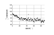
- FIG. 5 is a plot of the contact angle measurements.
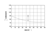
- FIG. 6 is a diagram showing an approximation curve of the measured values of the contact angle.
- FIG. 7 is a diagram showing estimated values of the amount of decrease in contact angle due to the effect of volatilization.
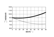
- FIG. 8 is a diagram showing the correction value of the estimated value.
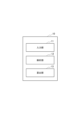
- FIG. 9 is a diagram illustrating an example of the configuration of a correction device.
- FIG. 10 is a diagram illustrating an example of a hardware configuration of the correction apparatus.
- contact angle correction method An example of a contact angle correction method according to the present embodiment will be described with reference to the flowchart in Fig. 1.
- a contact angle it may be understood to mean either an advancing contact angle, a receding contact angle, or both an advancing contact angle and a receding contact angle.
- step S1 a droplet is placed on the sample to be evaluated, and in step S2, the contact angle is measured at each tilt angle while changing the tilt angle of the sample.
- Figure 2 shows how the inclination angle of the sample is changed.
- Figure 2(a) shows the state in which the inclination angle ⁇ is not changed from the minimum inclination angle 0° after the droplet 200 is dropped onto the sample 100.
- Figure 2(b) shows the state in which the inclination angle ⁇ is set to 45°.
- Figure 2(c) shows the state in which the inclination angle ⁇ is set to the maximum inclination angle 90°.
- the advancing contact angle ⁇ a and the receding contact angle ⁇ r are measured at each inclination angle ⁇ while increasing the inclination angle ⁇ by 1° from the minimum inclination angle 0° to the maximum inclination angle 90°.
- the advancing contact angle ⁇ a is the contact angle in the direction in which the droplet 200 slides down
- the receding contact angle ⁇ r is the contact angle in the opposite direction.
- the advancing contact angle ⁇ a and the receding contact angle ⁇ r can be measured using an image of the droplet 200 photographed by the tangent method described in Non-Patent Document 2.
- the minimum and maximum tilt angles may be set to any value. For example, if the sample has a droplet that slides off at 30°, the maximum tilt angle may be set to 30°.
- step S3 a droplet is placed on the sample to be evaluated, and after the droplet is placed, in step S4, the sample is quickly set to the desired inclination angle and the contact angle is measured.
- Figure 3 shows the sample set to the desired tilt angle.
- the desired tilt angle is set to 45°, which is the intermediate angle between the minimum tilt angle of 0° and the maximum tilt angle of 90°.
- the tilt angle ⁇ of the sample 100 is quickly tilted to 45° to measure the advancing contact angle ⁇ a and the receding contact angle ⁇ r.
- the desired tilt angle is set to 15°.
- the desired tilt angle does not have to be an angle intermediate between the minimum and maximum tilt angles, as long as it is an angle between the minimum and maximum tilt angles.
- the desired tilt angle may be 30° or 60°.
- steps S1 and S2 are referred to as data 1, and the measurement results of steps S3 and S4 are referred to as data 2.
- data 1 is the measured value of the contact angle at each tilt angle from the minimum tilt angle to the maximum tilt angle
- data 2 is the measured value of the contact angle at the target tilt angle.
- data 1 is the measured value of the advancing contact angle at 1° increments from the minimum tilt angle of 0° to the maximum tilt angle of 90°
- data 2 is the measured value of the advancing contact angle at a tilt angle of 45°.
- step S5 the effect of volatilization on the contact angle is found from data 1 and data 2, and a correction value for the contact angle is obtained.
- Data 1 which is obtained by measuring the contact angle while changing the tilt angle from the minimum tilt angle to the maximum tilt angle, deviates from the original value due to the effects of volatilization because the greater the tilt angle, the greater the time that passes. Therefore, in this embodiment, data 2, which is obtained by measuring the contact angle at the desired tilt angle immediately after dropping the droplet, is obtained to find the effect of volatilization, and a correction value for the contact angle that cancels the effect of volatilization is obtained from data 1.
- the contact angle is measured by setting the sample to the desired tilt angle immediately after dropping the droplet, so the effect of volatilization can be ignored.
- the effect of volatilization can be found by comparing the contact angle of data 2 with the contact angle of data 1 at the desired tilt angle at which data 2 was measured.
- step S51 the device finds an approximation curve for Data 1.
- Fig. 5 shows the measured values of Data 1 and Data 2, with the tilt angle on the horizontal axis and the advancing contact angle on the vertical axis. The black circles are plots of Data 1, and the white circles are plots of Data 2.
- step S52 the device calculates the difference between data 1 and data 2. Specifically, the device substitutes the target tilt angle at which data 2 was measured into the approximation curve calculated in step S51 to calculate the advancing contact angle at the target tilt angle for data 1, and calculates the difference between the calculated advancing contact angle and data 2.
- Data 2 was measured at a target inclination angle of 45° and was 91°.
- the advancing contact angle when the inclination angle of the approximation curve for Data 1 was 45° was 75°, so the difference between Data 1 and Data 2 was calculated to be 16°.
- the difference between data 1 and data 2 may be calculated by the difference between the measurement value of data 1 at the desired tilt angle and data 2, without using an approximation curve.
- step S53 the device obtains an estimate of the amount of decrease in the advancing contact angle due to volatilization between the minimum and maximum tilt angles based on the difference obtained in step S52.
- the measured value of the minimum tilt angle of Data 1 is not affected by volatilization, and it is considered that there is almost no change in the advancing contact angle due to volatilization. It is considered that the amount of decrease in the advancing contact angle due to volatilization increases by a constant amount depending on the elapsed time, and an estimate of the amount of decrease in the advancing contact angle due to volatilization for each 1° increase in tilt angle is obtained by dividing the difference by the value obtained by subtracting the minimum tilt angle from the target tilt angle.
- the minimum tilt angle is 0°
- the target tilt angle is 45°
- the difference is 16°
- the estimated amount of decrease at a certain tilt angle is calculated by multiplying the estimated amount of decrease in advancing contact angle due to volatilization for each 1° increase in tilt angle by the value obtained by subtracting the minimum tilt angle from that tilt angle.
- Figure 7 shows the estimated amount of decrease in advancing contact angle due to volatilization between the minimum and maximum tilt angles, with the tilt angle on the horizontal axis and the estimated amount of decrease in advancing contact angle on the vertical axis.
- step S54 the device calculates a correction value for the advancing contact angle. Specifically, the device calculates the correction value for the advancing contact angle by adding an estimated value for the amount of decrease in the advancing contact angle between the minimum tilt angle and the maximum tilt angle calculated in step S53 to the approximation curve of data 1.
- Figure 8 shows the correction value for the advancing contact angle obtained by adding the estimated amount of decrease to the approximation curve of data 1.
- the solid line is the correction value for the advancing contact angle
- the dotted line is the approximation curve of data 1.
- the correction value for the contact angle may also be calculated by adding the estimated amount of decrease to the measured value of data 1.
- a correction device 10 shown in the figure includes an input unit 11, an analysis unit 12, and a calculation unit 13.
- the input unit 11 inputs still images or videos of droplets for measuring data 1 and data 2.
- the input unit 11 cuts out frames for each tilt angle from the video and transmits them to the analysis unit 12.
- the input unit 11 may input still images for each tilt angle for measuring data 1.
- the input unit 11 may be equipped with a camera to capture images of the droplets.
- the input unit 11 may input data 1 and data 2. When data 1 and data 2 are input, the contact angle measurement process by the analysis unit 12 is not necessary.
- the analysis unit 12 analyzes the captured image of the droplet to determine the contact angle (data 1 and data 2).
- the analysis unit 12 may display the image and accept input of a line segment indicating the contact angle from the operator.
- the calculation unit 13 calculates the effect of volatilization on the contact angle from data 1 and data 2 according to the flowchart in Figure 4, and calculates the correction value for data 1.
- the contact angle correction method of this embodiment obtains data 1 by measuring the contact angle at each tilt angle while changing the tilt angle from the minimum tilt angle to the maximum tilt angle, obtains data 2 by measuring the contact angle at a target tilt angle between the minimum tilt angle and the maximum tilt angle, determines the difference between the contact angle at the target tilt angle in data 1 and data 2, and corrects data 2 using the difference as the effect of volatilization on the contact angle. This allows a more accurate contact angle to be obtained by taking into account the effect of volatilization.
- the correction device 10 described above can be, for example, a general-purpose computer system including a central processing unit (CPU) 901, memory 902, storage 903, communication device 904, input device 905, and output device 906, as shown in FIG. 10.
- the correction device 10 is realized by the CPU 901 executing a predetermined program loaded onto the memory 902.
- This program can be recorded on a non-transitory computer-readable recording medium such as a magnetic disk, optical disk, or semiconductor memory, or can be distributed via a network.
Landscapes
- Physics & Mathematics (AREA)
- Health & Medical Sciences (AREA)
- Life Sciences & Earth Sciences (AREA)
- Chemical & Material Sciences (AREA)
- Analytical Chemistry (AREA)
- Biochemistry (AREA)
- General Health & Medical Sciences (AREA)
- General Physics & Mathematics (AREA)
- Immunology (AREA)
- Pathology (AREA)
- Image Processing (AREA)
Priority Applications (2)
| Application Number | Priority Date | Filing Date | Title |
|---|---|---|---|
| PCT/JP2023/023309 WO2024262003A1 (ja) | 2023-06-23 | 2023-06-23 | 接触角の補正方法 |
| JP2025527380A JPWO2024262003A1 (https=) | 2023-06-23 | 2023-06-23 |
Applications Claiming Priority (1)
| Application Number | Priority Date | Filing Date | Title |
|---|---|---|---|
| PCT/JP2023/023309 WO2024262003A1 (ja) | 2023-06-23 | 2023-06-23 | 接触角の補正方法 |
Publications (1)
| Publication Number | Publication Date |
|---|---|
| WO2024262003A1 true WO2024262003A1 (ja) | 2024-12-26 |
Family
ID=93935028
Family Applications (1)
| Application Number | Title | Priority Date | Filing Date |
|---|---|---|---|
| PCT/JP2023/023309 Ceased WO2024262003A1 (ja) | 2023-06-23 | 2023-06-23 | 接触角の補正方法 |
Country Status (2)
| Country | Link |
|---|---|
| JP (1) | JPWO2024262003A1 (https=) |
| WO (1) | WO2024262003A1 (https=) |
Citations (5)
| Publication number | Priority date | Publication date | Assignee | Title |
|---|---|---|---|---|
| JP2005152758A (ja) * | 2003-11-25 | 2005-06-16 | Seiko Epson Corp | 膜形成方法、デバイス製造方法および電気光学装置 |
| JP2006078477A (ja) * | 2004-08-10 | 2006-03-23 | Kanagawa Acad Of Sci & Technol | 液滴移動挙動の測定方法および装置 |
| CN101692011A (zh) * | 2009-09-08 | 2010-04-07 | 南京大学 | 一种控温湿同步测量液滴温度和滚动角的装置 |
| JP3178773U (ja) * | 2012-07-19 | 2012-09-27 | 協和界面科学株式会社 | 接触角計 |
| JP2013195399A (ja) * | 2012-03-22 | 2013-09-30 | Dainippon Printing Co Ltd | 細胞培養基材の検査方法及び検査装置、並びに細胞培養基材の製造方法 |
-
2023
- 2023-06-23 JP JP2025527380A patent/JPWO2024262003A1/ja active Pending
- 2023-06-23 WO PCT/JP2023/023309 patent/WO2024262003A1/ja not_active Ceased
Patent Citations (5)
| Publication number | Priority date | Publication date | Assignee | Title |
|---|---|---|---|---|
| JP2005152758A (ja) * | 2003-11-25 | 2005-06-16 | Seiko Epson Corp | 膜形成方法、デバイス製造方法および電気光学装置 |
| JP2006078477A (ja) * | 2004-08-10 | 2006-03-23 | Kanagawa Acad Of Sci & Technol | 液滴移動挙動の測定方法および装置 |
| CN101692011A (zh) * | 2009-09-08 | 2010-04-07 | 南京大学 | 一种控温湿同步测量液滴温度和滚动角的装置 |
| JP2013195399A (ja) * | 2012-03-22 | 2013-09-30 | Dainippon Printing Co Ltd | 細胞培養基材の検査方法及び検査装置、並びに細胞培養基材の製造方法 |
| JP3178773U (ja) * | 2012-07-19 | 2012-09-27 | 協和界面科学株式会社 | 接触角計 |
Also Published As
| Publication number | Publication date |
|---|---|
| JPWO2024262003A1 (https=) | 2024-12-26 |
Similar Documents
| Publication | Publication Date | Title |
|---|---|---|
| JP7116419B2 (ja) | 粒子測定装置、較正方法、および測定装置 | |
| CN110971810B (zh) | 机芯镜头回程差处理方法及装置 | |
| US9900512B2 (en) | Apparatus, method and computer program for image stabilization | |
| KR101672501B1 (ko) | 광 조건들을 변경하는 것으로 인한 픽셀 밀도 요건에서의 변화에 대한 필요를 결정하는 방법 및 장치 | |
| WO2019184410A1 (zh) | 虚拟现实设备的畸变参数测量方法及装置、测量系统 | |
| TWI630377B (zh) | 熱像檢測裝置 | |
| JP2018004918A5 (https=) | ||
| JP6546553B2 (ja) | 画像安定化方法及びシステム | |
| WO2024262003A1 (ja) | 接触角の補正方法 | |
| US8179431B2 (en) | Compound eye photographing apparatus, control method therefor, and program | |
| US11736797B2 (en) | Apparatus and method for controlling apparatus including an inclination mechanism for tilting an image sensor | |
| US20150296123A1 (en) | Advanced Fast Autofocusing | |
| US10911688B2 (en) | Control apparatus, imaging apparatus, and storage medium | |
| JP2019158402A (ja) | 平面形状測定装置 | |
| JP7763068B2 (ja) | 撮像装置の振れ補正効果の評価方法、評価装置およびプログラム | |
| CN116170690A (zh) | 一种图像拍摄的方法、装置、设备及可读存储介质 | |
| TW201823678A (zh) | 影像擷取裝置與其相位對焦的校正方法 | |
| US11722775B2 (en) | Image pickup apparatus and controlling method thereof | |
| CN113301330B (zh) | 一种利用电动调焦镜头的图像延迟在线检测方法及系统 | |
| JP6602089B2 (ja) | 画像処理装置及びその制御方法 | |
| WO2024262002A1 (ja) | 液滴除去性能の評価方法 | |
| CN121541358B (zh) | 一种自动对焦控制方法、系统及介质 | |
| JP2016206281A (ja) | 撮影システム、撮影装置、撮影方法、プログラムおよび記憶媒体 | |
| US20240233234A1 (en) | Image processing apparatus, image processing method, non-transitory computer-readable storage medium | |
| JP3287639B2 (ja) | スポット検査装置 |
Legal Events
| Date | Code | Title | Description |
|---|---|---|---|
| 121 | Ep: the epo has been informed by wipo that ep was designated in this application |
Ref document number: 23942435 Country of ref document: EP Kind code of ref document: A1 |
|
| ENP | Entry into the national phase |
Ref document number: 2025527380 Country of ref document: JP Kind code of ref document: A |
|
| WWE | Wipo information: entry into national phase |
Ref document number: 2025527380 Country of ref document: JP |
|
| NENP | Non-entry into the national phase |
Ref country code: DE |