WO2024261808A1 - フィーダ - Google Patents
フィーダ Download PDFInfo
- Publication number
- WO2024261808A1 WO2024261808A1 PCT/JP2023/022579 JP2023022579W WO2024261808A1 WO 2024261808 A1 WO2024261808 A1 WO 2024261808A1 JP 2023022579 W JP2023022579 W JP 2023022579W WO 2024261808 A1 WO2024261808 A1 WO 2024261808A1
- Authority
- WO
- WIPO (PCT)
- Prior art keywords
- tape
- feeder
- reel
- reel holder
- feeder body
- Prior art date
- Legal status (The legal status is an assumption and is not a legal conclusion. Google has not performed a legal analysis and makes no representation as to the accuracy of the status listed.)
- Ceased
Links
Images




Classifications
-
- H—ELECTRICITY
- H05—ELECTRIC TECHNIQUES NOT OTHERWISE PROVIDED FOR
- H05K—PRINTED CIRCUITS; CASINGS OR CONSTRUCTIONAL DETAILS OF ELECTRIC APPARATUS; MANUFACTURE OF ASSEMBLAGES OF ELECTRICAL COMPONENTS
- H05K13/00—Apparatus or processes specially adapted for manufacturing or adjusting assemblages of electric components
- H05K13/02—Feeding of components
Definitions
- This specification relates to a feeder.
- This feeder that feeds and transports a carrier tape by rotating a tape reel on which the carrier tape is wound (see, for example, Patent Document 1).
- This feeder comprises a feeder body as a housing, a reel holder provided in the feeder body for storing the tape reel, and a feed sprocket for feeding and transporting the carrier tape pulled out from the tape reel.
- the tape reel on which the carrier tape is wound is removably stored in the reel holder of the feeder body. When the tape reel is stored in this reel holder, the carrier tape is pulled out from the tape reel and set in a state in which the teeth of the feed sprocket are engaged with the feed hole.
- the carrier tape is pulled by the feed sprocket, pulled out from the tape reel, and fed and transported as the tape reel rotates.
- the purpose of this specification is to provide a feeder that can reduce equipment costs for feeder operation and save storage space.
- a feeder comprising a feeder body having a drive unit that applies a feed drive force to the carrier tape for transport, a reel holder that is detachable from the feeder body and holds a tape reel around which the carrier tape is wound, and an attachment unit that detachably attaches the reel holder to the feeder body.
- This disclosure makes it possible to reduce equipment costs for feeder operation and save storage space.
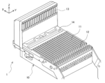
- FIG. 1 is a perspective view of a feeder setting table of a component mounting machine on which a feeder is set according to an embodiment of the present invention.
- 2 is a perspective view of a carrier tape and a tape reel around which the carrier tape is wound.
- FIG. FIG. 2 is a perspective view of a feeder according to an embodiment.
- FIG. 2 is a side view of the feeder according to the embodiment.
- 2 is a perspective view of a feeder body provided in the feeder of the embodiment.
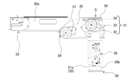
- FIG. 2 is a side view of a feeder body provided in the feeder of the embodiment.
- FIG. FIG. 2 is a perspective view of a reel holder provided in the feeder of the embodiment.
- FIG. 2 is a side view of a reel holder provided in the feeder of the embodiment.
- the feeder 20 is a device that supplies components to be mounted on a board to a component supply position S (see FIG. 4).
- the feeder 20 is removably incorporated in the component mounting machine 1.
- the component mounting machine 1 is provided on a board production line, and picks up or grasps components at the component supply position S and transfers them to the board.
- the component mounting machine 1 is equipped with a feeder set table 10.
- the feeder set table 10 is a table on which multiple feeders 20 are set. As shown in FIG. 1, the feeder set table 10 has slots 11.
- the slots 11 are gaps into which the feeders 20 are removably inserted.
- the slots 11 are formed in a shape that allows the feeders 20 to be supported vertically. Multiple slots 11 are arranged side by side on the feeder set table 10.
- the number of slots 11 on the feeder set table 10 is, for example, 20.
- the feeder set table 10 has clamp grooves 12 into which the feeders 20 fit, and connectors 13 to which the power lines and signal lines of the feeders 20 connect, corresponding to each slot 11.
- the feeder set table 10 also has a tape outlet 14 for discharging waste tape from the carrier tape 2 (see FIG. 2) that stores the components.
- Feeder 20 is capable of transporting carrier tape 2.
- the components that feeder 20 supplies are electronic components such as transistors, diodes, and resistors that make up electronic circuits. These components include, for example, very small components such as 0201 size (0.2 mm x 0.1 mm) and large components such as capacitors.
- the carrier tape 2 is formed in a long shape.
- the carrier tape 2 generally has a tape width that is determined in advance as a standard, such as 4 mm, 8 mm, 12 mm, 16 mm, or 24 mm.
- the carrier tape 2 has a base tape 2a and a cover tape 2b.
- the base tape 2a has a component storage section that stores components arranged at a predetermined interval in the tape longitudinal direction.
- the cover tape 2b is a film-like member that covers a component removal opening of the base tape 2a.
- the carrier tape 2 may be an embossed tape in which the component storage section of the base tape 2a protrudes downward, or it may be a paper tape with a groove-shaped component storage section on the surface.
- the carrier tape 2 is wound around a tape reel 3.
- the tape reel 3 is formed in a disk shape.
- the tape reel 3 is made of, for example, resin or cardboard.
- the tape reel 3 has a retaining hole 3a and a flange portion 3b.
- the retaining hole 3a is a through hole that penetrates in the direction of the rotation axis, which is necessary to hold the tape reel 3 in the feeder 20.
- the flange portion 3b is a portion that spreads out in a disk shape centered on the retaining hole 3a.
- the retaining hole 3a is located at the axis of the flange portion 3b, and extends in the reel width direction (hereinafter referred to as the reel width direction Y) that coincides with the tape width direction Y of the carrier tape 2 wound around the tape reel 3.
- the flange portions 3b are provided in pairs spaced apart in the reel width direction Y.
- the pair of flange portions 3b are arranged so as to sandwich the wound carrier tape 2.
- the pair of flange portions 3b are spaced apart in the reel width direction Y so as to leave a gap that is equal to or greater than the tape width of the carrier tape 2 to be wound.
- tape reels 3 are used in which the distance between the pair of flange portions 3b in the reel width direction Y (i.e., the reel width) is predetermined as a standard (e.g., JIS standard), but non-standard reels may also be used.
- the feeder 20 is, for example, a cassette-type tape feeder capable of storing the tape reel 3.
- the feeder 20 includes a feeder body 30, a reel holder 40, and an attachment portion 50, as shown in Figures 3 and 4 .
- the feeder body 30 is a main body member that forms a housing including the frame of the feeder 20 and the mounting portion that is attached to the slot 11 of the component mounting machine 1.
- the feeder body 30 is formed in a flat shape that can be attached to and detached from the slot 11 of the component mounting machine 1, and is formed in an L-shape when viewed from the side as shown in Figures 5 and 6.
- the feeder body 30 is formed so that an upper plate portion 30a extending in a substantially horizontal direction on the upper side and a standing plate portion 30b whose upper end portion is connected to the downstream portion in the tape transport direction X (the right end portion in Figure 6), which is one horizontal end portion of the upper plate portion 30a, are integrated together.
- the reel holder 40 is a member that holds the tape reel 3, and is a cassette member that can be attached to and detached from the feeder body 30.
- the reel holder 40 is formed in a flat shape, and is formed in a roughly angular (e.g., rectangular) shape in side view as shown in Figures 7 and 8.
- the reel holder 40 can be fitted onto the inner side of the L-shaped portion of the feeder body 30.
- One reel holder 40 that holds one tape reel 3 can be attached to one feeder body 30.
- each reel holder 40 has a common structure at the location where it is attached to the feeder body 30.
- the feeder body 30 has a drive unit 31.
- the drive unit 31 is a part that constitutes a tape transport mechanism that applies a feed drive force to the carrier tape 2 for transport.
- the drive unit 31 has a first drive source 32, a gear 33, and a first sprocket 34.
- the first drive source 32 is a drive motor such as an electric motor that generates a feed drive force.
- the first sprocket 34 is a disk body that transmits the feed drive force generated by the first drive source 32 to the carrier tape 2.
- the first drive source 32 and the first sprocket 34 mesh with each other via the gear 33. Note that the gear 33 may be configured with multiple gears meshing with each other.
- the feeder body 30 also has a transport path 35.
- the transport path 35 is a passage that transports and supports the carrier tape 2 pulled out from the tape reel 3.
- the transport path 35 contacts the lower surface of the carrier tape 2 and supports the carrier tape 2 from below.
- the transport path 35 extends along the tape transport direction X on the upper plate portion 30a. Specifically, the transport path 35 is inclined from the lower edge to the upper edge of the upper plate portion 30a from the upstream side to the downstream side in the tape transport direction X.
- the transport path 35 supports the carrier tape 2 on the upper surfaces of the inclined walls facing diagonally upward and the inner surfaces of the vertical walls facing laterally on both sides in the tape width direction Y.
- the first drive source 32, gear 33, and first sprocket 34 are positioned below the transport path 35 near where the upper plate portion 30a and the standing plate portion 30b intersect.
- the external teeth which are an engagement protrusion at the upper end of the first sprocket 34, protrude above the transport path 35 and engage with the feed hole of the carrier tape 2 that is pulled out from the tape reel 3 and transported on the transport path 35.
- the first drive source 32 When the first drive source 32 generates a feed drive force in this engaged state, the feed drive force rotates the first sprocket 34 via the gear 33. When this rotation occurs, the carrier tape 2 is fed and transported in the tape transport direction X.
- the feeder body 30 further has a tape guide 36.
- the tape guide 36 is a guide portion that guides the carrier tape 2 transported on the transport path 35.
- the tape guide 36 is disposed above the first sprocket 34 and faces the first sprocket 34 across the transport path 35.
- the carrier tape 2 is transported in the tape transport direction X while being sandwiched between the tape guide 36 and the transport path 35.
- the tape guide 36 is removably attached to the front and upper side of the feeder body 30, which is downstream in the tape transport direction X.
- the tape guide 36 may be replaceable with respect to the feeder body 30 depending on the type of carrier tape 2 to be transported.
- the tape guide 36 is formed with a U-shaped cross section so that it can abut against the upper and side surfaces of the carrier tape 2.
- the carrier tape 2 is guided against the upper and side walls of the tape guide 36 when transported in the tape transport direction X.
- the reel holder 40 has a reel holder 41.
- the reel holder 41 is a part that rotatably holds the tape reel 3 around which the carrier tape 2 is wound.
- the reel holder 41 forms a storage space that stores the tape reel 3.
- the reel holder 41 is configured so that one tape reel 3 can be detachably set therein.
- the reel holder 41 has a reel holding shaft that rotatably supports the tape reel 3, and a plate-shaped cover 41a that covers the tape reel 3 stored in the storage space from the outside in the reel width direction Y and can be opened and closed relative to the reel holder 40.
- the reel holder 40 also has a collection box 42.
- the collection box 42 is a box body in which the cover tape 2b peeled off from the base tape 2a of the carrier tape 2 is collected.
- the collection box 42 forms a space in which the cover tape 2b of a new carrier tape 2 wound around the tape reel 3 can be collected.
- the collection box 42 is disposed on the rear side of the reel holder 41, which is upstream in the tape transport direction X, in the reel holder 40.
- the collection box 42 has a plate-shaped cover 42a that closes the collection space from the outside in the reel width direction Y and can be opened and closed relative to the reel holder 40.
- the feeder body 30 has a second drive source 37 and a gear 38.
- the reel holder 40 has a second sprocket 43 and a gear 44.
- the second drive source 37 and gear 38 of the feeder body 30 and the second sprocket 43 and gear 44 of the reel holder 40 form a cover tape recovery mechanism that applies a recovery drive force for recovery to the cover tape 2b peeled off from the base tape 2a.
- the second driving source 37 is a driving motor such as an electric motor that generates a recovery driving force for recovering the cover tape 2b in the recovery box 42.
- the second sprocket 43 is a disk body that transmits the recovery driving force generated by the second driving source 37 to the cover tape 2b.
- the gear 38 is interposed between the second driving source 37 and the second sprocket 43, and meshes with the gears of the second driving source 37 and the second sprocket 43.
- the gear 38 is disposed near the lower end of the upper plate portion 30a of the feeder body 30.
- the second sprocket 43 is disposed near the upper end of the reel holder 40.
- the gear 38 and the second sprocket 43 are disposed on either side of the boundary between the feeder body 30 and the reel holder 40 when the reel holder 40 is attached to the feeder body 30, and mesh with each other.
- the gear 44 meshes with the gear of the second sprocket 43. There are multiple gears 44 meshing together.
- the cover tape 2b peeled off from the base tape 2a is guided to the recovery path 45 of the reel holder 40. Of the multiple gears 44, two gears 44 that mesh with each other at the downstream end are positioned with the recovery path 45 in between. The cover tape 2b engages with the two gears 44 in the recovery path 45.
- the second drive source 37 generates an auxiliary force to assist in feeding the carrier tape 2 pulled out from the tape reel 3 in the tape transport direction X, simultaneously with the generation of the recovery drive force described above.
- the second sprocket 43 is capable of transmitting the recovery drive force generated by the second drive source 37 to the cover tape 2b, and also transmitting the auxiliary force generated by the second drive source 37 to the carrier tape 2.
- the second sprocket 43 rotates only in one direction around its axis (clockwise in FIG. 8) due to the recovery drive force and the auxiliary force.
- the reel holder 40 has a feed path 49.
- the feed path 49 is a passage that transports and supports the carrier tape 2 pulled out from the tape reel 3.
- the external teeth of the second sprocket 43 engage with the feed holes of the carrier tape 2 that is pulled out from the tape reel 3 inside the reel holder 40 and transported on the feed path 49.
- the recovery drive force and the auxiliary force rotate the second sprocket 43 via the gear 38.
- the carrier tape 2 is fed in the tape feed direction X, and the gear 44 rotates in sync, so that the cover tape 2b is peeled off from the base tape 2a and fed toward the recovery box 42.
- the reel holder 40 has a peeling section 46.
- the peeling section 46 is a section where the cover tape 2b is peeled off from the base tape 2a of the carrier tape 2 pulled out from the tape reel 3.
- the peeling section 46 is provided at a location on the reel holder 40 adjacent to the entrance of the transport path 35 of the feeder body 30.
- the peeling section 46 has a folding section that folds back the cover tape 2b peeled off from the base tape 2a of the carrier tape 2 in the opposite direction to the tape transport direction X of the base tape 2a and guides it to the recovery path 45.
- a tape holding section (not shown) is provided on the back side of the peeling section 46 to hold the base tape 2a from which the cover tape 2b has been peeled off.
- This tape holding section is composed of, for example, a tape clamping section that clamps the base tape 2a on the feed path 49, a biasing section that generates a biasing force to close the tape clamping section, and a lever section that applies a force to open the tape clamping section against the biasing force of the biasing section.
- This tape holding section is normally closed and is opened when work is performed to clamp the base tape 2a or release that clamping.
- This tape holding section is closed before the reel holder 40 is attached to the feeder body 30, and is opened after attachment to allow tape transport.
- the reel holder 40 has a tip holder 47.
- the tip holder 47 is a portion that holds the tip of the cover tape 2b that is folded back at the peeling section 46.
- the tip holder 47 is located near the recovery path 45 in the reel holder 40, and is located between the folded back portion of the peeling section 46 and the recovery box 42.
- the tip holding portion 47 is composed of, for example, a tape clamping portion that clamps the cover tape 2b on the recovery path 45, a biasing portion that generates a biasing force to close the tape clamping portion, and a lever portion that applies a force to open the tape clamping portion against the biasing force of the biasing portion.
- the tape holding portion of the tip holding portion 47 is normally closed and is opened when an operation is performed to clamp the cover tape 2b or to release that clamping. This tape holding portion is closed before the reel holder 40 is attached to the feeder main body 30, and is opened after attachment so that the tape can be transported.
- the feeder body 30 has a control unit 39.
- the control unit 39 is a part that controls the driving of the first driving source 32 and the second driving source 37.
- the control unit 39 is mainly composed of a microcomputer and includes a control board and the like.
- the control unit 39 is disposed below the first driving source 32 and the first sprocket 34 in the standing plate portion 30b.
- the control unit 39 is electrically connected to the first driving source 32 and is electrically connected to the second driving source 37.
- the control unit 39 may drive the first drive source 32 and the second drive source 37 in synchronization with each other.
- the first drive source 32 and the second drive source 37 may each be driven intermittently so that the carrier tape 2 is transported intermittently at predetermined time intervals.
- the control unit 39 may have a function of managing the feeder information of the feeder 20 in addition to controlling the drive of the first drive source 32 and the second drive source 37.
- the control unit 39 may be capable of associating and linking the feeder information of the feeder main body 30 with the feeder information of the reel holder 40 attached to the feeder main body 30.
- the above-mentioned feeder information refers to information associated with unique identification information defined for each feeder body 30, each reel holder 40, and each tape reel 3.
- the feeder information may include, for example, the type and identification information of the tape guide 36 attached to the feeder body 30, the size of the reel holder 41 of the reel holder 40, the type and identification information of the tape reel 3 stored in the reel holder, the type and tape width of the carrier tape 2, etc.
- each housing of the feeder body 30, the reel holder 40, and the tape reel 3 is provided with a label or plate that stores the feeder information for that device.
- This feeder information can be read using a specified reading device.
- the feeder information is read in an external setup area or the like.
- This read feeder information is sent to the host computer and stored, and after storage, is used for checking associated feeder information, etc.
- the host computer is a device that is positioned higher than the feeder 20 and provides integrated control of the component mounting machine 1, etc.
- the mounting portion 50 is a portion that removably mounts the reel holder 40 to the feeder body 30.
- the mounting portion 50 has a positioning portion 51 and a clamp portion 52.
- the positioning portion 51 is a portion that positions the reel holder 40 relative to the feeder body 30.
- the clamp portion 52 is a portion that clamps the feeder body 30 and the reel holder 40 in a predetermined positional relationship.
- the "predetermined positional relationship” refers to a position in which, when the reel holder 40 is attached to the feeder body 30, the gear 38 on the second drive source 37 side and the second sprocket 43 mesh with each other, and the cover tape 2b is peeled off and the base tape 2a of the carrier tape 2 held by the tip holder 47 is engaged with the second sprocket 43, allowing it to be transferred to the transport path 35 of the feeder body 30 by transport.
- the positioning portion 51 has a body side portion 51a provided on the feeder body 30 and a reel side portion 51b provided on the reel holder 40.
- the body side portion 51a and the reel side portion 51b of the positioning portion 51 are formed with uneven shapes that can engage with each other.
- the body side portion 51a and the reel side portion 51b may each be provided in multiple locations.
- the body side portion 51a and the reel side portion 51b engage with each other when the reel holder 40 is attached to or detached from the feeder body 30, thereby positioning the reel holder 40 relative to the feeder body 30.
- the main body side portion 51a may extend like a rail along the direction in which the reel holder 40 is inserted into the feeder body 30 when the reel holder 40 is attached to or detached from the feeder body 30, and the reel side portion 51b may be a portion that is guided along the main body side portion 51a when the reel holder 40 is attached to or detached from the feeder body 30.
- either the main body side portion 51a or the reel side portion 51b may be formed with a bifurcated cross section, and the other may be formed with a plate shape that fits into the bifurcated cross section.
- the clamp unit 52 has the function of preventing the feeder body 30 and the reel holder 40 from being released from their integrated state after the attachment of the reel holder 40 to the feeder body 30 is completed and the feeder body 30 and the reel holder 40 are integrated in a predetermined positional relationship.
- the clamp unit 52 has a body side portion provided on the feeder body 30 and a reel side portion provided on the reel holder 40.
- the body side portion and the reel side portion of the clamp unit 52 may be configured to switch between fixing and releasing the feeder body 30 and the reel holder 40 by lever operation by an operator or a robot.
- the clamp portion 52 may include a spring that biases the reel holder 40 toward the release side relative to the feeder body 30 in the above-mentioned specified positional relationship, a hook portion that hooks the reel holder 40 onto the feeder body 30 against the biasing force of the spring and restricts the movement of the reel holder 40 toward the release side, and a lever portion that operates the hook portion.
- the feeder body 30 and the reel holder 40 are manufactured separately.
- the tape reel 3 around which the carrier tape 2 is wound is stored in the reel holder 41 of the reel holder 40 by an operator or a robot in an external setup area or the like.
- a new tape reel 3 is stored in exchange for the empty tape reel 3.
- the tape reel 3 is stored in the reel holder 41, if the cover tape 2b remains in the collection box 42, the cover tape 2b is discarded and the collection box 42 is emptied.
- the carrier tape 2 is pulled out from the tape reel 3 and the cover tape 2b is peeled off from the base tape 2a.
- the cover tape 2b is then folded back at the peeling section 46 and guided to the recovery path 45 where it engages with a gear, and the tip of the cover tape 2b is held by the tip holding section 47.
- the base tape 2a is also held by the tape holding section, and the feed holes of the base tape 2a engage with the external teeth of the second sprocket 43.
- the reel holder 40 is transportable, and can be positioned relative to the feeder body 30 at the mounting section 50 and attached to the feeder body 30 by an operator or robot.
- a number of reel holders 40 can be stored together in a reel storage (not shown) in the buffer station. Each reel holder 40 in the reel storage can be selected and attached to the feeder body 30. The selection of the reel holder 40 is performed by a host computer in accordance with a production plan for the board, and the selected reel holder 40 can be removed from the reel storage using a robot, etc.
- the reel holder 40 is positioned on the feeder body 30 by the attachment portion 50 and clamped in a predetermined positional relationship, thereby attaching the reel holder 40 to the feeder body 30.
- the feeder 20 in which the feeder body 30 and the reel holder 40 are integrated, is attached to the slot 11 of the component mounting machine 1.
- the control portion 39 is started up and is able to drive the first drive source 32 and the second drive source 37.
- the control unit 39 drives the second drive source 37 to rotate the second sprocket 43.
- the carrier tape 2 is fed in the tape feed direction X on the feed path 49, and the cover tape 2b is fed toward the recovery box 42 on the recovery path 45.
- the base tape 2a of the carrier tape 2 is transferred from the reel holder 40 to the feeder body 30 by the auxiliary force of the second drive source 37 and sent out along the transport path 35 toward the component supply position S, and the cover tape 2b peeled off from the base tape 2a at the peeling section 46 is collected in the collection box 42 by the collection drive force of the second drive source 37.
- the components stored in each component storage section of the base tape 2a are exposed in sequence and can be removed to the outside. After being exposed, when the components reach the component supply position S, they are held by a suction nozzle of the component mounting machine 1 or the like and transferred to the board.
- the control unit 39 drives the first drive source 32 to rotate the first sprocket 34 after the leading end of the base tape 2a reaches the component supply position S or in synchronization with the drive of the second drive source 37.
- the first sprocket 34 rotates with the carrier tape 2 engaged with it, the portion of the carrier tape 2 that includes the component storage section from which the components have been removed is discharged from the tape discharge port 14 as a waste tape portion.
- the feeder 20 When the remaining amount of carrier tape 2 stored in the tape reel 3 of the feeder 20 becomes low or when the feeder 20 is no longer scheduled to be used by the component mounting machine 1, the feeder 20 is removed from the slot 11 of the component mounting machine 1, and the reel holder 40 is removed from the feeder body 30 in an external setup area or the like. During this removal, the base tape 2a is cut at the waste tape portion or the like. Then, after the reel holder 40 is removed from the feeder body 30, a new reel holder 40 or a reel holder 40 with a new tape reel 3 stored in the reel holder 41 is attached to the feeder body 30, and the feeder 20 is attached to the slot 11 of the component mounting machine 1.
- the feeder body 30 has a drive unit 31 including a first drive source 32, a gear 33, and a first sprocket 34 for feeding and transporting the carrier tape 2 (specifically, the base tape 2a), and further has a second drive source 37 for collecting the cover tape 2b in a collection box 42, and a control unit 39 for driving and controlling the drive sources 32, 37.
- the reel holder 40 also has a reel holder 41 that rotatably holds the tape reel 3, and further has a collection box 42, a peeling portion 46, a second sprocket 43, and a gear 44.
- the reel holder 41 and the collection box 42 are integrated in a reel holder 40 that can be attached and detached to the feeder body 30. For this reason, for example, when the feeder 20 runs out of parts during board production, the reel holder 40 can be removed from the feeder body 30, and the tape reel 3 that has run out of parts and the collection box 42 that is full of cover tape 2b can be simultaneously separated from the feeder body 30, including the drive unit 31, second drive source 37, and control unit 39, and collected together. Also, by attaching the reel holder 40 to the feeder body 30, a new tape reel 3 and an empty collection box 42 without cover tape 2b can be simultaneously integrated into the feeder body 30.
- the reel holder 40 does not incorporate the drive unit 31, the second drive source 37, and the control unit 39. Therefore, the reel holder 40 itself is less expensive than the entire feeder 20 including the feeder body 30. Therefore, even when it is necessary to prepare surplus equipment, for example, in consideration of a setup change, it is not necessary to prepare the entire feeder 20 including the feeder body 30 as surplus equipment, and it is sufficient to prepare the reel holder 40 as surplus equipment. This makes it possible to keep the equipment costs for feeder operation lower than when the entire feeder 20 including the feeder body 30 is prepared as surplus equipment. In addition, the space for storing surplus equipment in an external setup area, etc., can be limited to the reel holder 40. This makes it possible to save space in storing the feeder 20.
- the reel holder 40 is provided with a peeling section 46 that peels the cover tape 2b from the base tape 2a of the carrier tape 2.
- the peeling section 46 has a folding section that folds back the cover tape 2b that has been peeled off from the base tape 2a of the carrier tape 2 that has been pulled out from the tape reel 3 held by the reel holder 41.
- the handling of the cover tape 2b that has been peeled off from the base tape 2a can be completed within the reel holder 40.
- the tip of the cover tape 2b peeled off from the base tape 2a at the peeling section 46 can be held by the tip holder 47, and when the cover tape 2b is held, the tip of the base tape 2a engages with the upper external teeth of the second sprocket 43.
- the reel holder 40 since it is possible to hold the respective tips of the base tape 2a and cover tape 2b of the carrier tape 2 within the reel holder 40, the reel holder 40 can be transported or attached to the feeder body 30 while holding the base tape 2a and the cover tape 2b peeled off from the base tape 2a.
- the second drive source 37 In the feeder 20, the second drive source 37 generates a recovery drive force for recovering the cover tape 2b in the recovery box 42, and at the same time generates an auxiliary force for assisting in the feeding and transporting of the carrier tape 2 pulled out from the tape reel 3.
- the second drive source 37 is disposed in the feeder body 30, and the force generated by the second drive source 37 is transmitted to the reel holder 40 side using a gear 38 and a second sprocket 43.
- the cover tape 2b peeled off from the base tape 2a of the carrier tape 2 pulled out from the tape reel 3 held in the reel holder 41 of the reel holder 40 can be guided to the collection box 42 within the reel holder 40 without passing through the feeder body 30.
- the base tape 2a from which the cover tape 2b has been peeled off can be given an auxiliary force for feeding and transporting by the second drive source 37, the carrier tape 2 on the reel holder 40 side can be automatically guided to the component supply position S on the feeder body 30 side immediately after the reel holder 40 is attached to the feeder body 30. Furthermore, since the base tape 2a engages with the external teeth of the first sprocket 34 when it reaches the component supply position S, the feed drive force can then be applied to the base tape 2a by the first drive source 32, and the base tape 2a can be fed and transported sequentially.
- the feeder information of the feeder body 30 and the reel holder 40, as well as the feeder information of the tape reel 3, is read, and the feeder information is associated with each other and stored in a storage unit such as a host computer. Then, after the feeder information is stored, the setting of the feeder 20 into the slot 11 of the component mounting machine 1 is controlled based on the feeder information. Therefore, one reel holder 40 can be selected from multiple types of reel holders 40, and the feeder 20 attached to the feeder body 30 can be appropriately associated with the built-in carrier tape 2, and the mounting of components on the board in the component mounting machine 1 can be appropriately performed.
- the reel holder 40 when the reel holder 40 is removed from the feeder body 30 of the feeder 20, the feeder information of the feeder body 30, the reel holder 40, and even the tape reel 3 is read, and the feeder information is deleted from the memory unit. Therefore, the association between the feeder 20 and the carrier tape 2 can be dissolved after the reel holder 40 is removed from the feeder body 30, and it is possible to avoid the association continuing for an unnecessarily long period of time.
- the cover tape 2b of the carrier tape 2 is completely peeled off from the base tape 2a at the peeling portion 46, and the reel holder 40 has a recovery box 42 for recovering the cover tape 2b.
- the present disclosure is not limited to this, and the cover tape 2b may be so-called partially peeled off from the base tape 2a, and after the components are removed from the component storage section in this partially peeled state, the cover tape 2b may be rejoined to the base tape 2a and discharged together with the base tape 2a to the outside of the feeder.
- control unit 39 controls the driving of both the first driving source 32 and the second driving source 37.
- control unit 39 may control the driving of only the first driving source 32.
Landscapes
- Engineering & Computer Science (AREA)
- Manufacturing & Machinery (AREA)
- Microelectronics & Electronic Packaging (AREA)
- Supply And Installment Of Electrical Components (AREA)
Priority Applications (2)
| Application Number | Priority Date | Filing Date | Title |
|---|---|---|---|
| JP2025527220A JPWO2024261808A1 (https=) | 2023-06-19 | 2023-06-19 | |
| PCT/JP2023/022579 WO2024261808A1 (ja) | 2023-06-19 | 2023-06-19 | フィーダ |
Applications Claiming Priority (1)
| Application Number | Priority Date | Filing Date | Title |
|---|---|---|---|
| PCT/JP2023/022579 WO2024261808A1 (ja) | 2023-06-19 | 2023-06-19 | フィーダ |
Publications (1)
| Publication Number | Publication Date |
|---|---|
| WO2024261808A1 true WO2024261808A1 (ja) | 2024-12-26 |
Family
ID=93935151
Family Applications (1)
| Application Number | Title | Priority Date | Filing Date |
|---|---|---|---|
| PCT/JP2023/022579 Ceased WO2024261808A1 (ja) | 2023-06-19 | 2023-06-19 | フィーダ |
Country Status (2)
| Country | Link |
|---|---|
| JP (1) | JPWO2024261808A1 (https=) |
| WO (1) | WO2024261808A1 (https=) |
Citations (5)
| Publication number | Priority date | Publication date | Assignee | Title |
|---|---|---|---|---|
| JP2012248784A (ja) * | 2011-05-31 | 2012-12-13 | Juki Corp | 電子部品供給装置 |
| WO2015170398A1 (ja) * | 2014-05-09 | 2015-11-12 | 富士機械製造株式会社 | テープフィーダ |
| JP2020092111A (ja) * | 2018-12-03 | 2020-06-11 | 三井金属計測機工株式会社 | カバーフィルム剥離機能付きデバイス実装用フィルムフィーダー |
| JP2022140485A (ja) * | 2020-03-25 | 2022-09-26 | パナソニックIpマネジメント株式会社 | キャリアテープ処理装置およびキャリアテープ処理方法 |
| WO2022219714A1 (ja) * | 2021-04-13 | 2022-10-20 | 株式会社Fuji | フィーダ及び部品実装機 |
-
2023
- 2023-06-19 JP JP2025527220A patent/JPWO2024261808A1/ja active Pending
- 2023-06-19 WO PCT/JP2023/022579 patent/WO2024261808A1/ja not_active Ceased
Patent Citations (5)
| Publication number | Priority date | Publication date | Assignee | Title |
|---|---|---|---|---|
| JP2012248784A (ja) * | 2011-05-31 | 2012-12-13 | Juki Corp | 電子部品供給装置 |
| WO2015170398A1 (ja) * | 2014-05-09 | 2015-11-12 | 富士機械製造株式会社 | テープフィーダ |
| JP2020092111A (ja) * | 2018-12-03 | 2020-06-11 | 三井金属計測機工株式会社 | カバーフィルム剥離機能付きデバイス実装用フィルムフィーダー |
| JP2022140485A (ja) * | 2020-03-25 | 2022-09-26 | パナソニックIpマネジメント株式会社 | キャリアテープ処理装置およびキャリアテープ処理方法 |
| WO2022219714A1 (ja) * | 2021-04-13 | 2022-10-20 | 株式会社Fuji | フィーダ及び部品実装機 |
Also Published As
| Publication number | Publication date |
|---|---|
| JPWO2024261808A1 (https=) | 2024-12-26 |
Similar Documents
| Publication | Publication Date | Title |
|---|---|---|
| JP4820728B2 (ja) | 部品供給装置、並びに表面実装機 | |
| JP4856761B2 (ja) | 部品テープ・フィーダ | |
| JP6681344B2 (ja) | フィーダ装置 | |
| EP3041334B1 (en) | Feeder | |
| US11765876B2 (en) | Exchange device | |
| US11974402B2 (en) | Component supply device | |
| CN107950084B (zh) | 带式供料器 | |
| WO2019087291A1 (ja) | 部品供給装置及びテープフィーダー | |
| JP7536168B2 (ja) | 部品実装機 | |
| WO2020162159A1 (ja) | 部品供給装置 | |
| WO2024261808A1 (ja) | フィーダ | |
| JP2005212029A (ja) | 収納テープの切断装置及びその切断方法 | |
| EP3809809A1 (en) | Exchange device | |
| CN112237058B (zh) | 带式供料器 | |
| CN112292922B (zh) | 供料器 | |
| JP6822993B2 (ja) | 電子部品装着装置及び電子部品装着装置における自動ローディング方法 | |
| JPH07242284A (ja) | 部品供給カセット | |
| WO2025046773A1 (ja) | フィーダ | |
| JP2000077893A (ja) | 表面実装機 | |
| JP6979992B2 (ja) | 部品実装機のカセット式フィーダ入替システム | |
| JP7221399B2 (ja) | 部品実装機、テープフィーダ、テープセットユニット | |
| JP2017085027A (ja) | フィーダ | |
| WO2025234038A1 (ja) | テープ取外しシステム | |
| WO2024241522A1 (ja) | テープフィーダ | |
| JP2001028495A (ja) | 部品供給装置 |
Legal Events
| Date | Code | Title | Description |
|---|---|---|---|
| 121 | Ep: the epo has been informed by wipo that ep was designated in this application |
Ref document number: 23942247 Country of ref document: EP Kind code of ref document: A1 |
|
| ENP | Entry into the national phase |
Ref document number: 2025527220 Country of ref document: JP Kind code of ref document: A |
|
| WWE | Wipo information: entry into national phase |
Ref document number: 2025527220 Country of ref document: JP |
|
| NENP | Non-entry into the national phase |
Ref country code: DE |