WO2024257792A1 - 電極基材、電極基材積層体、電極及び二次電池、並びにその製造方法 - Google Patents
電極基材、電極基材積層体、電極及び二次電池、並びにその製造方法 Download PDFInfo
- Publication number
- WO2024257792A1 WO2024257792A1 PCT/JP2024/021328 JP2024021328W WO2024257792A1 WO 2024257792 A1 WO2024257792 A1 WO 2024257792A1 JP 2024021328 W JP2024021328 W JP 2024021328W WO 2024257792 A1 WO2024257792 A1 WO 2024257792A1
- Authority
- WO
- WIPO (PCT)
- Prior art keywords
- particles
- solid electrolyte
- electrode
- substrate
- active material
- Prior art date
- Legal status (The legal status is an assumption and is not a legal conclusion. Google has not performed a legal analysis and makes no representation as to the accuracy of the status listed.)
- Ceased
Links
Images

















Classifications
-
- H—ELECTRICITY
- H01—ELECTRIC ELEMENTS
- H01M—PROCESSES OR MEANS, e.g. BATTERIES, FOR THE DIRECT CONVERSION OF CHEMICAL ENERGY INTO ELECTRICAL ENERGY
- H01M4/00—Electrodes
- H01M4/02—Electrodes composed of, or comprising, active material
- H01M4/36—Selection of substances as active materials, active masses, active liquids
- H01M4/48—Selection of substances as active materials, active masses, active liquids of inorganic oxides or hydroxides
- H01M4/52—Selection of substances as active materials, active masses, active liquids of inorganic oxides or hydroxides of nickel, cobalt or iron
- H01M4/525—Selection of substances as active materials, active masses, active liquids of inorganic oxides or hydroxides of nickel, cobalt or iron of mixed oxides or hydroxides containing iron, cobalt or nickel for inserting or intercalating light metals, e.g. LiNiO2, LiCoO2 or LiCoOxFy
-
- H—ELECTRICITY
- H01—ELECTRIC ELEMENTS
- H01M—PROCESSES OR MEANS, e.g. BATTERIES, FOR THE DIRECT CONVERSION OF CHEMICAL ENERGY INTO ELECTRICAL ENERGY
- H01M10/00—Secondary cells; Manufacture thereof
- H01M10/05—Accumulators with non-aqueous electrolyte
- H01M10/052—Li-accumulators
-
- H—ELECTRICITY
- H01—ELECTRIC ELEMENTS
- H01M—PROCESSES OR MEANS, e.g. BATTERIES, FOR THE DIRECT CONVERSION OF CHEMICAL ENERGY INTO ELECTRICAL ENERGY
- H01M10/00—Secondary cells; Manufacture thereof
- H01M10/05—Accumulators with non-aqueous electrolyte
- H01M10/052—Li-accumulators
- H01M10/0525—Rocking-chair batteries, i.e. batteries with lithium insertion or intercalation in both electrodes; Lithium-ion batteries
-
- H—ELECTRICITY
- H01—ELECTRIC ELEMENTS
- H01M—PROCESSES OR MEANS, e.g. BATTERIES, FOR THE DIRECT CONVERSION OF CHEMICAL ENERGY INTO ELECTRICAL ENERGY
- H01M10/00—Secondary cells; Manufacture thereof
- H01M10/05—Accumulators with non-aqueous electrolyte
- H01M10/056—Accumulators with non-aqueous electrolyte characterised by the materials used as electrolytes, e.g. mixed inorganic/organic electrolytes
-
- H—ELECTRICITY
- H01—ELECTRIC ELEMENTS
- H01M—PROCESSES OR MEANS, e.g. BATTERIES, FOR THE DIRECT CONVERSION OF CHEMICAL ENERGY INTO ELECTRICAL ENERGY
- H01M10/00—Secondary cells; Manufacture thereof
- H01M10/05—Accumulators with non-aqueous electrolyte
- H01M10/056—Accumulators with non-aqueous electrolyte characterised by the materials used as electrolytes, e.g. mixed inorganic/organic electrolytes
- H01M10/0561—Accumulators with non-aqueous electrolyte characterised by the materials used as electrolytes, e.g. mixed inorganic/organic electrolytes the electrolyte being constituted of inorganic materials only
- H01M10/0562—Solid materials
-
- H—ELECTRICITY
- H01—ELECTRIC ELEMENTS
- H01M—PROCESSES OR MEANS, e.g. BATTERIES, FOR THE DIRECT CONVERSION OF CHEMICAL ENERGY INTO ELECTRICAL ENERGY
- H01M10/00—Secondary cells; Manufacture thereof
- H01M10/05—Accumulators with non-aqueous electrolyte
- H01M10/056—Accumulators with non-aqueous electrolyte characterised by the materials used as electrolytes, e.g. mixed inorganic/organic electrolytes
- H01M10/0564—Accumulators with non-aqueous electrolyte characterised by the materials used as electrolytes, e.g. mixed inorganic/organic electrolytes the electrolyte being constituted of organic materials only
- H01M10/0565—Polymeric materials, e.g. gel-type or solid-type
-
- H—ELECTRICITY
- H01—ELECTRIC ELEMENTS
- H01M—PROCESSES OR MEANS, e.g. BATTERIES, FOR THE DIRECT CONVERSION OF CHEMICAL ENERGY INTO ELECTRICAL ENERGY
- H01M10/00—Secondary cells; Manufacture thereof
- H01M10/05—Accumulators with non-aqueous electrolyte
- H01M10/058—Construction or manufacture
- H01M10/0585—Construction or manufacture of accumulators having only flat construction elements, i.e. flat positive electrodes, flat negative electrodes and flat separators
-
- H—ELECTRICITY
- H01—ELECTRIC ELEMENTS
- H01M—PROCESSES OR MEANS, e.g. BATTERIES, FOR THE DIRECT CONVERSION OF CHEMICAL ENERGY INTO ELECTRICAL ENERGY
- H01M4/00—Electrodes
- H01M4/02—Electrodes composed of, or comprising, active material
- H01M4/13—Electrodes for accumulators with non-aqueous electrolyte, e.g. for lithium-accumulators; Processes of manufacture thereof
- H01M4/131—Electrodes based on mixed oxides or hydroxides, or on mixtures of oxides or hydroxides, e.g. LiCoOx
-
- H—ELECTRICITY
- H01—ELECTRIC ELEMENTS
- H01M—PROCESSES OR MEANS, e.g. BATTERIES, FOR THE DIRECT CONVERSION OF CHEMICAL ENERGY INTO ELECTRICAL ENERGY
- H01M4/00—Electrodes
- H01M4/02—Electrodes composed of, or comprising, active material
- H01M4/13—Electrodes for accumulators with non-aqueous electrolyte, e.g. for lithium-accumulators; Processes of manufacture thereof
- H01M4/136—Electrodes based on inorganic compounds other than oxides or hydroxides, e.g. sulfides, selenides, tellurides, halogenides or LiCoFy
-
- H—ELECTRICITY
- H01—ELECTRIC ELEMENTS
- H01M—PROCESSES OR MEANS, e.g. BATTERIES, FOR THE DIRECT CONVERSION OF CHEMICAL ENERGY INTO ELECTRICAL ENERGY
- H01M4/00—Electrodes
- H01M4/02—Electrodes composed of, or comprising, active material
- H01M4/13—Electrodes for accumulators with non-aqueous electrolyte, e.g. for lithium-accumulators; Processes of manufacture thereof
- H01M4/139—Processes of manufacture
- H01M4/1391—Processes of manufacture of electrodes based on mixed oxides or hydroxides, or on mixtures of oxides or hydroxides, e.g. LiCoOx
-
- H—ELECTRICITY
- H01—ELECTRIC ELEMENTS
- H01M—PROCESSES OR MEANS, e.g. BATTERIES, FOR THE DIRECT CONVERSION OF CHEMICAL ENERGY INTO ELECTRICAL ENERGY
- H01M4/00—Electrodes
- H01M4/02—Electrodes composed of, or comprising, active material
- H01M4/13—Electrodes for accumulators with non-aqueous electrolyte, e.g. for lithium-accumulators; Processes of manufacture thereof
- H01M4/139—Processes of manufacture
- H01M4/1397—Processes of manufacture of electrodes based on inorganic compounds other than oxides or hydroxides, e.g. sulfides, selenides, tellurides, halogenides or LiCoFy
-
- H—ELECTRICITY
- H01—ELECTRIC ELEMENTS
- H01M—PROCESSES OR MEANS, e.g. BATTERIES, FOR THE DIRECT CONVERSION OF CHEMICAL ENERGY INTO ELECTRICAL ENERGY
- H01M4/00—Electrodes
- H01M4/02—Electrodes composed of, or comprising, active material
- H01M4/36—Selection of substances as active materials, active masses, active liquids
- H01M4/58—Selection of substances as active materials, active masses, active liquids of inorganic compounds other than oxides or hydroxides, e.g. sulfides, selenides, tellurides, halogenides or LiCoFy; of polyanionic structures, e.g. phosphates, silicates or borates
-
- H—ELECTRICITY
- H01—ELECTRIC ELEMENTS
- H01M—PROCESSES OR MEANS, e.g. BATTERIES, FOR THE DIRECT CONVERSION OF CHEMICAL ENERGY INTO ELECTRICAL ENERGY
- H01M4/00—Electrodes
- H01M4/02—Electrodes composed of, or comprising, active material
- H01M4/62—Selection of inactive substances as ingredients for active masses, e.g. binders, fillers
-
- H—ELECTRICITY
- H01—ELECTRIC ELEMENTS
- H01M—PROCESSES OR MEANS, e.g. BATTERIES, FOR THE DIRECT CONVERSION OF CHEMICAL ENERGY INTO ELECTRICAL ENERGY
- H01M4/00—Electrodes
- H01M4/02—Electrodes composed of, or comprising, active material
- H01M2004/021—Physical characteristics, e.g. porosity, surface area
-
- H—ELECTRICITY
- H01—ELECTRIC ELEMENTS
- H01M—PROCESSES OR MEANS, e.g. BATTERIES, FOR THE DIRECT CONVERSION OF CHEMICAL ENERGY INTO ELECTRICAL ENERGY
- H01M2300/00—Electrolytes
- H01M2300/0017—Non-aqueous electrolytes
- H01M2300/0065—Solid electrolytes
-
- H—ELECTRICITY
- H01—ELECTRIC ELEMENTS
- H01M—PROCESSES OR MEANS, e.g. BATTERIES, FOR THE DIRECT CONVERSION OF CHEMICAL ENERGY INTO ELECTRICAL ENERGY
- H01M2300/00—Electrolytes
- H01M2300/0088—Composites
- H01M2300/0094—Composites in the form of layered products, e.g. coatings
-
- Y—GENERAL TAGGING OF NEW TECHNOLOGICAL DEVELOPMENTS; GENERAL TAGGING OF CROSS-SECTIONAL TECHNOLOGIES SPANNING OVER SEVERAL SECTIONS OF THE IPC; TECHNICAL SUBJECTS COVERED BY FORMER USPC CROSS-REFERENCE ART COLLECTIONS [XRACs] AND DIGESTS
- Y02—TECHNOLOGIES OR APPLICATIONS FOR MITIGATION OR ADAPTATION AGAINST CLIMATE CHANGE
- Y02E—REDUCTION OF GREENHOUSE GAS [GHG] EMISSIONS, RELATED TO ENERGY GENERATION, TRANSMISSION OR DISTRIBUTION
- Y02E60/00—Enabling technologies; Technologies with a potential or indirect contribution to GHG emissions mitigation
- Y02E60/10—Energy storage using batteries
Definitions
- This disclosure relates to an electrode substrate, an electrode substrate laminate, an electrode and a secondary battery, and a method for manufacturing the same.
- secondary batteries are composed of electrodes (positive and negative electrodes) and an electrolyte, and are charged and discharged by the movement of ions between the electrodes via the electrolyte.
- Such secondary batteries are used in a wide range of applications, from small devices such as mobile phones to large devices such as electric vehicles. For this reason, there is a demand for further improvements in the performance of secondary batteries.
- all-solid-state batteries which use inorganic solid electrolytes as the electrolyte
- all-solid-state batteries are expected to improve the safety and increase the capacity and power output of secondary batteries.
- the volume of the active material particles changes, and the conductive paths in the electrode, particularly between the electrode and the current collector and between the electrode and the electrolyte, are easily cut off.
- a mitigation portion is provided inside the electrode to mitigate the effect of the volume change.
- Patent Document 1 discloses an electrode that has multiple ceramic crystal particles of an electrode active material or solid electrolyte material, and is provided with aggregates of carbon particles that have voids at the grain boundaries between the crystals.
- At least one aspect of the present disclosure is directed to providing an electrode substrate, an electrode substrate laminate, an electrode, and a secondary battery that have excellent ion conductivity while mitigating the effects of volumetric fluctuations in active material particles and can suppress a decrease in output.
- another aspect of the present disclosure is directed to providing a method for manufacturing an electrode substrate, an electrode substrate laminate, an electrode, and a secondary battery.
- An electrode substrate used in the manufacture of an electrode is A resin substrate, and active material particles and solid electrolyte particles on the resin substrate, a particle layer including the active material particles and the solid electrolyte particles is formed on the resin substrate;
- the number-based cumulative 50% particle diameter calculated from the distribution of equivalent circle diameters of primary particles of the active material particles is defined as an average equivalent circle diameter ra of the active material particles
- the number-based cumulative 50% particle diameter calculated from the distribution of equivalent circle diameters of primary particles of the solid electrolyte particles is defined as an average equivalent circle diameter re of the solid electrolyte particles
- a ratio (re/ra) of the average equivalent circular diameter re to the average equivalent circular diameter ra is 0.01 or more and 2.0 or less
- the solid electrolyte particles Particles having a particle size exceeding a cumulative 10% particle size on a number basis from the small particle size side in a distribution of equivalent circle diameters of primary particles of the solid electrolyte particles are defined
- an electrode substrate laminate is provided in which multiple layers of the above-mentioned electrode substrates are laminated.
- an electrode for a secondary battery which is characterized by being a sintered body of the above-mentioned electrode base material. Also provided is an electrode characterized by being a sintered body of an electrode base material laminate in which a plurality of the above-mentioned electrode base materials are laminated.
- a secondary battery includes an electrode that is a sintered body of the electrode substrate, and an electrolyte layer adjacent to the electrode.
- a method for producing an electrode substrate used in the production of an electrode comprising the steps of: The production method comprises the steps of: preparing the resin substrate having an adhesive portion; disposing the active material particles and the first solid electrolyte particles on a surface of the adhesive portion; a particle settling step of settling the first solid electrolyte particles and the active material particles arranged on the surface of the adhesive portion onto the adhesive portion; and disposing second solid electrolyte particles in the adhesion portions between the settled first electrolyte particles and the active material particles.
- the electrode substrate is The active material particles and the solid electrolyte particles are disposed on the resin substrate. a particle layer including the active material particles and the solid electrolyte particles is formed on the resin substrate;
- a ratio (re/ra) of the average equivalent circular diameter re to the average equivalent circular diameter ra is 0.01 or more and 2.0 or less;
- the solid electrolyte particles include solid electrolyte particles P2 and solid electrolyte particles P3, the cumulative 50% particle size (r50) in the volume-based particle size distribution of the primary particles of the solid electrolyt
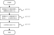
- a method for producing an electrode comprising the steps of: A step of laminating a plurality of the electrode base materials to form a laminate; removing the resin substrate from the laminate to obtain a three-dimensional object; and pressing the three-dimensional object to obtain an electrode.
- a method for producing a secondary battery comprising the steps of: The production method comprises the steps of: preparing an electrode by the electrode manufacturing method; and laminating the electrode, the current collector, and the electrolyte.
- At least one aspect of the present disclosure provides an electrode substrate, an electrode, and a secondary battery that have excellent ion conductivity while mitigating volumetric fluctuations in active material particles and can suppress a decrease in output, as well as methods for manufacturing the electrode substrate, the electrode, and the secondary battery.
- FIG. 1 is a conceptual diagram showing a method for producing an electrode substrate.
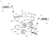
- FIG. 2 is a diagram showing a schematic configuration of the particle arrangement device 1.
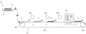
- FIG. 3 is a diagram showing a schematic configuration of the filling device.
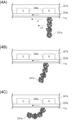
- 4A to 4C are schematic diagrams showing the stages of the state of the filler being carried on the first substrate.
- FIG. 5 is an enlarged view of the vicinity of the surface of the first base material.
- FIG. 6A is a diagram showing a schematic configuration of a filling device when brush fibers are used as the support material
- FIG. 6B is a diagram showing a schematic configuration of a filling device when an elastic material is used as the support material.
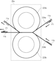
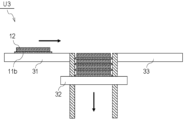
- FIG. 7 is a diagram illustrating a schematic configuration of the transfer unit.
- FIG. 1 is a conceptual diagram showing a method for producing an electrode substrate.
- FIG. 2 is a diagram showing a schematic configuration of the particle arrangement device 1.
- FIG. 3 is a diagram showing a schematic configuration of the filling device.
- FIG. 13 is a schematic view of the electrode substrate after the third step in the manufacturing method thereof, as viewed from above (the particle layer side).
- FIG. 14 is a schematic view of the electrode substrate after the fourth step in the manufacturing method thereof, as viewed from above (the particle layer side).
- FIG. 15 is a schematic diagram of a third filling device that does not use a belt device.
- FIG. 16 is a schematic diagram illustrating the operation of the filling device.
- FIG. 17 is a conceptual diagram showing a method for manufacturing an electrode.
- FIG. 18 is a diagram showing a schematic configuration of a laminate forming apparatus.
- FIG. 19 is a diagram showing a schematic configuration of a sintering apparatus.
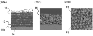
- FIG. 20A is an SEM image of a cross section of a laminate after the first step of a method for manufacturing an electrode
- FIG. 20B is an SEM image of a cross section of a three-dimensional object after the second step
- FIG. 20C is an SEM image of the top of the three-dimensional object.
- FIG. 21 is a diagram illustrating a schematic diagram of the overall configuration of an additive manufacturing system.
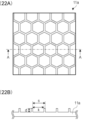
- FIG. 22A is a diagram showing a schematic structure of the upper surface of a first base material having a concave-convex pattern formed on its surface
- FIG. 22B is a cross-sectional view taken along line AA of FIG. 22A.
- 23A is an SEM image of the top of the electrode substrate of Example 1
- FIG. 23B is an enlarged image of FIG.
- FIG. 23A, and FIG. 23C is an SEM image of a cross section of the electrode substrate of Example 1.
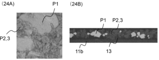
- 24A is an SEM image of the top of the electrode substrate of Comparative Example 2
- FIG. 24B is an SEM image of the cross section of the electrode substrate of Comparative Example 2.
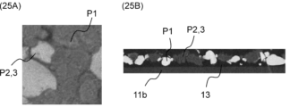
- 25A is an SEM image of the top of the electrode substrate of Comparative Example 5
- FIG. 25B is an SEM image of the cross section of the electrode substrate of Comparative Example 5.
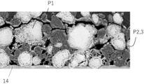
- FIG. 26 is a BIB-SEM image of a cross section of an electrode produced using the electrode base material of Example 1.
- FIG. 27 is a schematic diagram of an electrode substrate manufactured using the electrode substrate of Example 1.
- FIG. 28 is a BIB-SEM image of a cross section of an electrode produced using the electrode base material of Comparative Example 2.
- FIG. 29 is a BIB-SEM image of a cross section of an electrode produced using the electrode base material of Comparative Example 5.
- FIG. 30 is a diagram showing an example of an SEM image of the upper surface (particle layer side) of the electrode substrate.
- FIG. 31 is a diagram showing an example of an image used for calculating the coverage ratio.
- FIG. 32 is a diagram showing an example of a cross-sectional image of an electrode substrate photographed by an electron microscope.
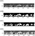
- FIG. 33A is an example of an image cut out from the SEM image used to calculate ra to show only the particle layer
- FIG. 33B is an example of a binarized image
- FIG. 33C is an example of an image from which noise has been removed
- FIG. 33D is an example of an image after each particle has been detected.
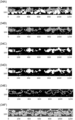
- FIG. 34A is an example of a binarized image of an SEM image used to calculate re
- FIG. 34B is an example of an image in which only solid electrolyte particles are represented by white pixels
- FIG. 34C is an example of an image in which noise has been removed
- FIG. 34D is an example of an image in which expansion processing has been performed on the white parts
- FIG. 34E is an example of an image showing a boundary region
- FIG. 34F is an example of an image after each particle has been detected.
- FIG. 35 shows a BIB-SEM image and an example of a peak in the distribution of active material particles.
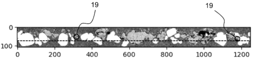
- FIG. 36 is a diagram showing an example of the center positions and reference lines of second solid electrolyte particles.
- the active material and the electrolyte are in contact with each other in a solid state, so it is difficult to obtain a sufficient contact area and to form an interface.
- the active material aggregates, the aggregated active material has even less contact with the solid electrolyte, and the ion conductivity is likely to decrease.
- the active material particles undergo volumetric changes during the process of ion insertion and removal. This volumetric change can easily break the conduction paths within the electrode, particularly between the electrode and the current collector and between the electrode and the electrolyte, leading to a deterioration in cycle characteristics.
- the inventors have investigated a structure that can form a good interface between the active material and the electrolyte while providing a layer inside the electrode that can reduce the effect of the volumetric fluctuation of the active material.
- a structure By unevenly disposing specific electrolyte particles in the electrode substrate, a structure can be obtained in which a uniform dense portion of the electrolyte particles is provided on the substrate side or the opposite side to the substrate of the electrode substrate, and a uniform void portion is provided on the opposite side of the dense portion.
- the above-mentioned embodiment is realized by using an electrode base material in which active material particles and solid electrolyte particles are arranged on a resin base material with the characteristics of the present disclosure.
- a plurality of electrode base materials can be laminated to form an electrode base material laminate.
- the electrode base material and the electrode base material laminate can also be used as materials for electrodes.
- the mitigation of volumetric variation is evaluated conveniently using an index called the "cycle characteristics" of a prototype battery, and the ionic conductivity is evaluated conveniently using an index called the "rate characteristics" of a prototype battery.
- the electrode substrate, the electrode substrate laminate, the electrode, and the secondary battery using them, as well as the manufacturing method thereof, will be described in detail below.
- the electrode substrate of the present disclosure can be used in the manufacture of electrodes for secondary batteries.
- a positive electrode substrate using positive electrode active material particles will be described as an example, but the electrode substrate of the present disclosure can be used for both positive and negative electrodes.
- the electrode substrate includes a resin substrate, active material particles on the resin substrate, and solid electrolyte particles. A particle layer including the active material particles and the solid electrolyte particles is formed on the resin substrate.
- the resin substrate is a substrate made of a material containing a resin.
- a substrate made of an organic material such as a resin As the substrate, it is possible to easily remove the substrate by heating in the manufacturing process of the electrode substrate described later.
- the resin contained in the material of the resin substrate is not particularly limited, and examples thereof include polyesters such as polyethylene (PE), polypropylene (PP) and polyethylene terephthalate (PET), and polyamides such as nylon. Of these, it is preferable to use PET from the viewpoints of its decomposition temperature and the low toxicity of gas generated during thermal decomposition.
- the active material particles are not particularly limited and known active materials can be used.
- a composite oxide containing lithium can be used.
- Li-Co oxide active material particles such as LiCoO 2 , LiMO 2 (M is one element selected from the group consisting of Ni, Mn, and Co)
- Li-PO 4 oxide active material particles lithium vanadium compounds (Li 3 V 2 (PO 4 ) 3 , LiVOPO 4 ), olivine phosphate compounds (LiMPO 4 (M is one or more elements selected from the group consisting of Co, Ni, Mn, Fe, Mg, V, Nb, Ti, Al, and Zr)), and the like
- LiMPO 4 Li is one or more elements selected from the group consisting of Co, Ni, Mn, Fe, Mg, V, Nb, Ti, Al, and Zr
- a positive electrode active material that does not contain lithium may be used.
- metal oxides MnO 2 , V 2 O 5 , etc.
- fluorides FeF 3 , VF 3 , etc.
- a positive electrode active material that does not contain lithium it can be used by disposing metallic lithium containing lithium or a negative electrode active material doped with lithium ions as the negative electrode active material and starting with discharging.
- the present inventors have revealed that, among the above positive electrode active material particles, the use of Li-Co oxide-based active material particles increases the surface area of the positive electrode active material particles, improving the output characteristics of the secondary battery (JP Patent Publication No. 2020-198301). Furthermore, Li-PO4 oxide-based active material particles are very stable because the covalent bond between P-O is strong and oxygen release is suppressed. For this reason, it is preferable to include Li-Co oxide-based active material particles and Li-PO4 oxide-based active material particles among the above positive electrode active material particles.
- the active material particles may be a commercially available product, or may be prepared separately as a material.
- An example of the Li-Co oxide active material particles that can be used is Cellseed C-5H (trade name, manufactured by Nippon Chemical Industry Co., Ltd.) (LiCoO 2 ).
- An example of LiMO 2 (M is an element selected from the group consisting of Ni, Mn, and Co) is Cellseed NMC (trade name, manufactured by Nippon Chemical Industry Co., Ltd.) (LiNi (1-x-y) Mn x Co y O 2 ).
- An example of the Li-PO 4 oxide active material particles that can be used is LiFePO 4 (manufactured by Toshima Manufacturing Co., Ltd.).
- active material particles having low electronic conductivity such as LiFePO4 are used, the particle surfaces may be coated with carbon by a general method.
- the active material particles may be used alone or in combination of two or more kinds.
- the solid electrolyte particles are not particularly limited, and ion-conductive solids that are normally used in all-solid-state batteries can be used.
- the Li-B oxide-based solid electrolyte particles and the Li-Yb oxide-based solid electrolyte particles can be sintered at a relatively low temperature (700° C. or less), so that the reaction with the positive electrode active material particles during sintering can be suppressed and ion conductivity can be maintained.
- a relatively low temperature 700° C. or less
- the solid electrolyte particles to be used may be commercially available products, or may be separately prepared as a material.
- Examples of the Li-B oxide solid electrolyte particles that can be used include Li 3 BO 3 (manufactured by Toshima Manufacturing Co., Ltd.) and particles in which part of the O in Li 3 BO 3 is replaced with C.
- Examples of the Li-Yb oxide solid electrolyte particles that can be used include Li 5.9 Yb 0.81 La 0.09 Zr 0.1 (BO 3 ) 3 .
- the cumulative 50% particle size (by number) calculated from the distribution of equivalent circle diameters of primary particles of the active material particles is defined as the average equivalent circle diameter ra of the active material particles
- the cumulative 50% particle size (by number) calculated from the distribution of equivalent circle diameters of primary particles of the solid electrolyte particles is defined as the average equivalent circle diameter re of the solid electrolyte particles.
- the circle equivalent diameter refers to the diameter of a sphere (circle) having a volume (area) equal to the volume (area) of the particle.
- the second solid electrolyte particles are a particle group having a smaller equivalent circle diameter of primary particles than the first solid electrolyte particles among all the solid electrolyte particles.
- first solid electrolyte particles and the second solid electrolyte particles By disposing the first solid electrolyte particles and the second solid electrolyte particles in specific regions of the electrode substrate by a method described later, it is possible to provide uniform voids and uniform dense portions inside the electrode. As a result, ions are easily conducted from the active material particles to the electrolyte while mitigating the effect of volume fluctuation of the active material particles inside the electrode.
- the equivalent circle diameter of the primary particles of the first solid electrolyte particles is not particularly limited, but is preferably, for example, 1 to 100 ⁇ m, and more preferably 2 to 50 ⁇ m.
- the equivalent circle diameter of the primary particles of the second solid electrolyte particles is not particularly limited as long as it is smaller than that of the first solid electrolyte particles; for example, the equivalent circle diameter of the primary particles of the second solid electrolyte particles is preferably 1 ⁇ 2 or less, and more preferably 1 ⁇ 3 or less, of the equivalent circle diameter of the first solid electrolyte particles.
- the ratio of the circle-equivalent diameter of the primary particles of the second solid electrolyte particles to the circle-equivalent diameter of the primary particles of the first solid electrolyte particles is not particularly limited, but is preferably, for example, 0.50 or less, and more preferably 0.30 or less.
- the electrode base material has a particle layer including active material particles and solid electrolyte particles formed on a resin base material.
- the active material particles and the first solid electrolyte particles are arranged adjacent to each other.
- a uniform dense portion of the active material particles and the solid electrolyte particles is provided, and the active material particles and the solid electrolyte particles can be sufficiently contacted with each other.
- the ion conductivity can be improved.
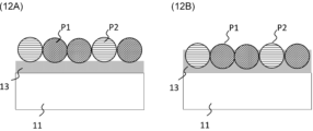
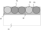
- first particles P1 as active material particles and second particles P2 that can correspond to first solid electrolyte particles are arranged on a resin substrate as a material of the electrode substrate.
- the active material particles and the first solid electrolyte particles can be controlled so as to be arranged adjacent to each other in the electrode substrate.
- the formation of a particle layer in the electrode substrate and the adjacent arrangement of the active material particles and the first solid electrolyte particles can be confirmed, for example, by observation using a SEM.
- the second solid electrolyte particles are unevenly distributed on the side of the particle layer that contacts the resin substrate (one side in the stacking direction of the resin substrate and the particle layer in the particle layer) or on the opposite side to the resin substrate side (the other side in the stacking direction of the resin substrate and the particle layer in the particle layer) with respect to the reference line.
- the reference line indicates the peak position of the distribution of the active material particles in the stacking direction of the resin substrate and the resin layer in the particle layer. The method of determining the reference line and the method of judging the uneven distribution will be described later.
- the resin base material, the unevenly distributed second solid electrolyte particles, the active material particles, and the first solid electrolyte particles are arranged in this order from the lower side of the electrode base material (the side on which the particle layer is not formed).
- the resin base material, the active material particles, the first solid electrolyte particles, and the unevenly distributed second solid electrolyte particles may be arranged in this order from the lower side of the electrode base material (the side on which the particle layer is not formed).
- a dense portion of the solid electrolyte particles is provided on the side in contact with the resin substrate or on the opposite side to the resin substrate side, and a uniform void portion is provided on the opposite side to the dense portion.
- the influence of the volume fluctuation of the active material particles can be mitigated.
- 80% or more of the second solid electrolyte particles are unevenly distributed on the opposite side to the resin substrate side.
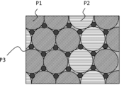
- third particles P3 that may correspond to the second solid electrolyte particles are disposed on a resin substrate as a material for the electrode substrate by a method described later, whereby the second solid electrolyte particles can be controlled to be unevenly distributed in the electrode substrate in the above-described state.
- the second solid electrolyte particles present on the resin substrate are identified, and if 80% or more by number of the identified particles are present on the side in contact with the resin substrate or on the side opposite to the resin substrate, the second solid electrolyte particles are determined to be unevenly distributed.
- a method for identifying the second solid electrolyte particles and a method for determining uneven distribution will be described later.
- the average equivalent circular diameter ra of the active material particles is the cumulative 50% particle diameter (by number) calculated from the distribution of the equivalent circular diameters of the primary particles of the active material particles.
- the average equivalent circular diameter re of the solid electrolyte particles is the cumulative 50% particle diameter (by number) calculated from the distribution of the equivalent circular diameters of the primary particles of the solid electrolyte particles.
- the ratio of the average equivalent circular diameter re to the average equivalent circular diameter ra (re/ra) is 0.01 or more and 2.0 or less.
- Active material particles often have higher electronic conductivity than solid electrolyte particles, and the degree of contact between active material particles tends to affect electronic conductivity within the electrode.
- re/ra 0.01 or more
- the average equivalent circular diameter re of the primary particles of the solid electrolyte particles is appropriately larger than the average equivalent circular diameter ra of the active material particles, so that the cohesive force and adhesive force of the solid electrolyte particles can be kept within appropriate ranges.
- the cohesive force of the solid electrolyte particles By controlling the cohesive force of the solid electrolyte particles to an appropriate range where the cohesive force is not excessive, the solid electrolyte particles can be easily mixed appropriately when stirred with a carrier, which will be described later.
- the solid electrolyte particles can be prevented from covering the upper part of the active material particles arranged on the electrode substrate. Therefore, contact between the active material particles is not hindered, and high electronic conductivity in the electrode is maintained.
- the ratio re/ra being 2.0 or less indicates that the average equivalent circular diameter re of the primary particles of the solid electrolyte particles is not excessively large relative to the average equivalent circular diameter ra of the active material particles and is within an appropriate range, so that more active material particles can be disposed on the electrode substrate without impeding contact between the active material particles.
- the solid electrolyte particles and the active material particles are disposed on the resin substrate.
- re/ra is 2.0 or less, the unevenness of the substrate surface is reduced. Therefore, when the electrode substrate is laminated by the method described below, the active material particles and the solid electrolyte particles, or the active material particles and the solid electrolyte particles in the substrate lamination direction can be sufficiently contacted without being hindered. This makes it possible to maintain high ion conductivity of the battery and improve the rate characteristics.
- a battery with high volume energy density can be manufactured.
- re/ra is preferably 0.05 or more, more preferably 0.10 or more, and even more preferably 0.50 or more. It is also preferably 1.8 or less, more preferably 1.5 or less, and even more preferably 1.0 or less. For example, preferred ranges include 0.05 to 1.8, 0.10 to 1.5, and 0.50 to 1.0.
- ra is not particularly limited, it is preferably 0.1 to 100 ⁇ m, more preferably 0.5 to 20 ⁇ m, and further preferably 1 to 10 ⁇ m. Although there are no particular limitations, re is preferably 0.01 to 50 ⁇ m, more preferably 0.05 to 10 ⁇ m, and further preferably 0.1 to 5 ⁇ m.
- the method for producing the electrode substrate includes the following steps. (1) A preparation step of preparing a resin substrate having an adhesive portion. (2) A first step of disposing first particles P1 on the surface of the adhesive portion (S101 in FIG. 1). (3) A second step of disposing second particles P2 on the surface of the adhesive portion (S102 in FIG. 1). (4) A third step (S103 in FIG. 1) of allowing the first particles P1 and the second particles P2 to settle in the adhesive portion. (5) A fourth step (S104 in FIG. 1 ) of arranging third particles P3, which have an average equivalent circular diameter smaller than those of the first particles P1 and the second particles P2, in contact with the settled first particles P1 or the second particles P2.
- a resin substrate having an adhesive portion is prepared.
- the term "having an adhesive portion” refers to an adhesive portion being provided on a part or the entire surface of the resin substrate.
- the resin substrate may be a substrate containing the above-mentioned resin.
- the method for providing the adhesive portion is not particularly limited, but a method of applying an adhesive to the surface of the resin substrate is preferable.
- the adhesive is not particularly limited, and any known adhesive can be used, for example, an acrylic adhesive, a rubber adhesive, a silicone adhesive, or a thermoplastic resin or a photocurable resin whose adhesive strength changes depending on disturbances such as heat or light.
- the first step is a step of disposing the first particles P1 on the surface of the adhesive portion of the resin substrate
- the second step is a step of disposing the second particles P2 on the surface of the adhesive portion of the resin substrate.
- 1 illustrates the second step (S102) following the first step (S101), but the order of the first and second steps is not particularly limited. That is, the step of arranging the second particles P2 on the surface of the adhesive portion may be followed by the step of arranging the first particles P1.
- the first particles P1 are active material particles.
- the above-described active material particles can be used as the first particles P1.
- the particle size of the primary particles of the first particles P1 is not particularly limited, but for example, the cumulative 10% particle size (r10) in the volumetric particle size distribution is preferably 0.1 to 10.0 ⁇ m, more preferably 1.0 to 7.0 ⁇ m.
- the cumulative 50% particle size (r50) in the volumetric particle size distribution is preferably 0.5 to 20.0 ⁇ m, more preferably 2.0 to 10.0 ⁇ m.
- the cumulative 90% particle size (r90) in the volumetric particle size distribution is preferably 2.0 to 20.0 ⁇ m, more preferably 3.0 to 15.0 ⁇ m.
- the second particles P2 are solid electrolyte particles, and may correspond to the first solid electrolyte particles in the electrode substrate.
- the above-mentioned materials may be used as the solid electrolyte particles.
- the cumulative 50% particle size (r50) in the volume-based particle size distribution of the primary particles of the second particles P2 is larger than the r50 of the primary particles of the third particles P3 described later.
- the particle size of the primary particles of the second particles P2 is not particularly limited as long as it is larger than that of the third particles P3.
- the cumulative 10% particle size (r10) in the volume-based particle size distribution of the primary particles of the second particles P2 is preferably 0.5 to 10.0 ⁇ m, and more preferably 1.0 to 7.0 ⁇ m.
- the cumulative 50% particle size (r50) in the volume-based particle size distribution is preferably 1.0 to 20.0 ⁇ m, and more preferably 5.0 to 15.0 ⁇ m.
- the cumulative 90% particle size (r90) in the volume-based particle size distribution is preferably 5.0 to 50.0 ⁇ m, and more preferably 10.0 to 30.0 ⁇ m.
- the ratio of the particle size of the primary particles of the first particles P1 to the particle size of the primary particles of the second particles P2 is not particularly limited.
- the ratio of the cumulative 50% particle size (r50(P1)) in the volume-based particle size distribution of the primary particles of the first particles P1 to the cumulative 50% particle size (r50(P2)) in the volume-based particle size distribution of the primary particles of the second particles P2, ⁇ (r50(P1))/(r50(P2)) ⁇ is preferably 0.05 to 20.0, and more preferably 0.1 to 2.0.
- the first particles P1 are active material particles.
- the second particles P2 are particles that can correspond to the first solid electrolyte particles in the manufactured electrode substrate. That is, in the manufacturing method of the electrode substrate, the first and second steps can be said to be steps of arranging the active material particles and the first solid electrolyte particles on the surface of the adhesive portion. In the first and second steps, particles are arranged on the adhesive portion of the resin base material using a particle arrangement device.
- particle arrangement device 1 and particle arrangement device 2 that can be used will be described in order.
- FIG. 2 is a diagram showing a schematic configuration of the particle arrangement device 1.
- the particle placement device 1 has a first storage container 21a that stores and supplies the first substrate 11a, a first belt device 22a that transports the first substrate 11a, and a pattern forming device 23 that forms a concave-convex pattern on the first substrate 11a.
- the particle arrangement device 1 has a first filling device 24a that arranges the first particles P1 in the recesses of the concave-convex pattern formed on the first substrate 11a.
- the particle arrangement device 1 has a second storage container 21b that stores and supplies the second substrate 11b, and a second belt device 22b that transports the second substrate 11b.
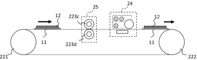
- the particle arrangement device 1 has a transfer section 25a in which the rollers 223 of the first belt device 22a and the second belt device 22b face each other, and the first particles P1 are transferred from the first substrate 11a to the second substrate 11b in the transfer section 25a.
- the particle placement device 1 has a second filling device 24b that places the second particles P2 in the non-transfer area on the second substrate 11b.
- a peeling and recovery device for peeling and recovering the first substrate 11a from the first belt device 22a after transfer and various cleaning devices, are omitted.
- the pattern forming device 23 corresponds to a first placement means that places the first particles P1 in a pattern on the second substrate 11b.
- the second filling device 24b corresponds to a second placement means that places the second particles P2 in areas on the second substrate 11b where the first particles P1 are not placed.
- the first substrate 11a is supplied from the first storage container 21a to the first belt device 22a by a supplying means (not shown).
- a pattern forming device 23 it is preferable that at least the surface of the first base material 11a is made of a material that has high wettability with the ultraviolet-curable liquid.
- the surface of the first base material 11a is smooth.
- the first substrate 11a may be a sheet made of a resin such as polyester that has been subjected to a hydrophilic or lipophilic treatment to match the UV-curable liquid (water-based or oil-based) to be used.
- the first substrate 11a may be a substrate that is individually cut out like cut paper, a continuous substrate wound into a roll like roll paper, or a continuous substrate that is alternately folded like continuous paper.
- the first belt device 22a transports the supplied first substrate 11a to a pattern forming position of the pattern forming device 23.
- the first belt device 22a has drive rollers 221a and 222a, a pressure roller 223a, and a belt-like transport member 224a suspended between them. At this time, the pressure roller 223a rotates driven by the drive rollers.
- the conveying member 224a is preferably made of a material selected from resin or metal, and for example, a polyimide resin belt can be used.
- the driving rollers 221a and 222a are preferably made of metal rollers, and for example, stainless steel metal rollers can be used.
- the pressure roller 223a is preferably a soft roller with an elastic layer on its surface, and for example, a soft roller with an elastic layer of silicone rubber on the surface of a stainless steel core can be used.
- the first belt device 22a is used as the conveying device for conveying the first base material 11a, but a roller device can be used instead of the belt device.
- a roller device can be used instead of the belt device.
- the pattern forming device 23 forms a fine uneven pattern on the first substrate 11a that has been transported to the pattern forming position.
- Methods for forming the uneven pattern include UV imprinting, thermal imprinting, UV inkjet printing, printing, and laser etching.
- the pattern forming device 23 When the pattern forming device 23 forms a concave-convex pattern by the UV imprint method, the pattern forming device 23 has a coating means for coating an ultraviolet-curable liquid on the first substrate 11a.
- the ultraviolet-curable liquid for example, an ultraviolet-curable resin such as ultraviolet-curable liquid silicone rubber can be used.
- the pattern forming device 23 also has an imprinting means for imprinting a mold having a concave-convex pattern formed on its surface onto the ultraviolet-curable liquid on the first substrate 11a, and a light source for irradiating the ultraviolet-curable liquid with ultraviolet rays.
- ultraviolet-curable liquid silicone rubber (PDMS) or resin is used as the ultraviolet-curable liquid
- a film mold is used as the mold
- a UV lamp is used as the light source.
- the opening diameter (width) of the recesses of the uneven pattern on the first base material 11a is preferably larger than the cumulative 50% particle diameter (median diameter) based on volume of the first particles P1. Also, the opening diameter (width) of the recesses is preferably smaller than the average size of the carrier material S1.
- the opening diameter of the recesses of the uneven pattern is preferably the opening diameter in the short side direction of the recesses, and more preferably the maximum opening diameter in the short side direction of the recesses.
- the first particle P1 can come into contact with the bottom or side (typically the bottom) of the recesses of the uneven pattern.
- the support material S1 cannot come into contact with the bottom or side of the recesses. This allows the first particle P1 that comes into contact with the bottom or side of the recess to be captured by the uneven pattern, while the support material S1 cannot be captured by the uneven pattern.
- the pattern forming device 23 forms an uneven pattern on the first substrate 11a, but a substrate with a previously formed uneven pattern on its surface may be used as the first substrate 11a.
- the pattern forming device 23 may also form an uneven pattern directly on the surface of the transport member 224a of the first belt device 22a, or a transport member having an uneven pattern on its surface may be used as the transport member 224a.
- a metal belt such as stainless steel or aluminum, and form the uneven pattern on the surface by micromachining techniques such as laser etching, wet etching, or dry etching.
- the filler 241a has first particles P1 and a carrier material S1 that carries the first particles P1.
- the filler 241a is a mixture of multiple powders including a powder composed of multiple first particles P1 and a powder composed of multiple carrier materials S1.
- the filler 241a contained in the filling container 242a is thoroughly mixed when stirred and transported by the stirring screw member 243a.
- the first particles P1 are carried on the surface of the carrier material S1.
- the forces acting between the particles when carried include electrostatic forces due to frictional charging, van der Waals forces, liquid bridging forces, etc.
- the support material S1 is a magnetic particle.
- the support material S1 is preferably a particle in which the surface of a resin particle in which a ferrite core particle or a magnetic body is dispersed is coated with a resin composition.
- a standard carrier Standard Carrier P02 manufactured by the Japan Imaging Society
- the particle size and material of the support material S1 are appropriately selected according to the particle size and material of the first particle P1. This allows the first particle P1 to be stably supported. In addition, even if the first particle P1 has a small particle size and is prone to agglomeration, the support material S1 plays a role of loosening the particles by stirring and conveying them.
- the particle size of the support material S1 can be appropriately adjusted by the size of the recess (area, width, depth). For example, the cumulative 50% particle size (median diameter) based on volume is preferably 50 to 100 ⁇ m.
- the recovery member 244a has a roller 245a that can rotate in the direction of the arrow d2 in the figure, and a magnet 246a that is disposed inside the roller 245a and fixed to the filling container 242a.
- the magnetic member 247a is disposed opposite the filling container 242a via the transport member 224a, and has a magnet 248a inside.
- the magnet 246a has a plurality of N poles and S poles arranged alternately along the rotation direction of the recovery member 244a.
- the magnet 248a has a plurality of N poles and S poles arranged alternately along the transport direction of the transport member 224a.
- the magnet 246a has a magnetic pole (N1 pole in FIG. 3) of a different polarity at a position closest to and facing the most downstream magnetic pole (S1 pole in FIG. 3) of the magnet 248a, and an N2 pole of the same polarity as the N1 pole is arranged at the most downstream position.
- the magnet 246a and the magnet 248a may be composed of a plurality of magnets, and the type of magnets constituting the magnet 246a and the magnet 248a is not particularly limited.
- a permanent magnet such as a rare earth magnet, a ferrite magnet, a neodymium magnet, a samarium-cobalt magnet, or a plastic magnet, or a means for generating a magnetic field such as an electromagnet may be used.
- the magnet 248a may be configured to be movable in the transport direction of the first base material 11a or in the opposite direction.
- a regulating member for regulating the filler 241a on the first base material 11a, or a recovery member for re-recovering the filler 241a that cannot be recovered by the recovery member 244a may be provided upstream or downstream of the recovery member 244a in the transport direction of the transport member 224a.
- the recovery member for re-recovery may be a member similar to the recovery member 244a, or a recovery member that performs recovery by air blowing, from simple members such as a fixed magnet or a regulating member.
- FIGS. 4A, 4B, and 4C are schematic diagrams of the filler 241a being transported on the first substrate 11a.
- the filler 241a other than the filler forming one magnetic hair is omitted from the illustration.
- the filler 241a on the first substrate 11a forms a magnetic hair along the magnetic field lines of the formed magnetic field, and is transported while changing the shape of the magnetic hair as the first substrate 11a moves, as shown in FIG. 4A, FIG. 4B, and FIG. 4C.
- the transport speed v2 of the filler 241a is smaller than the moving speed v1 of the first substrate 11a when the filler 241a moves away from the magnetic pole, and is larger in the opposite case.
- the filler 241a on the first substrate 11a has a relative speed that is not 0 with respect to the first substrate 11a.
- the particle size of the first particles P1 is smaller than the opening diameter of the recesses of the uneven pattern 111a, and the particle size of the first support material S1 is larger than the opening diameter of the recesses, so the first particles P1 can contact the bottom surface (bottom) and side portions of the recesses of the uneven pattern 111a, but the support material S1 cannot.
- the first particles P1 in the filler 241a selectively contact the bottom surface and side portions of the recesses.
- the first particles P1 that come into contact with the recesses are strongly restrained by the physical restraining force due to the structure of the uneven pattern 111a and by non-electrostatic adhesive forces such as electrostatic adhesion and adhesive forces with the structural materials that make up the first base material 11a and the uneven pattern 111a, and are detached from the support material S1.
- the first particles P1 are supported on the surface of the support material S1, but when the filler 241a is stirred, supplied, or transported, there may be first particles P1 that are not supported by the support material S1.
- the recovery member 244a is disposed with a gap between it and the first transport member 224a.
- the filler 241a is transported to the vicinity of the most downstream magnetic pole (S1 pole) of the magnet 248a, and is influenced by the magnetic field formed by the magnet 246a, and moves from the first base material 11a to the recovery member 244a and is recovered (dotted line c in FIG. 3).
- the recesses of the uneven pattern 111a on the surface of the first base material 11a are in sufficient contact with the plurality of fillers 241a. Therefore, the first particles P1 are selectively and densely arranged in the recesses of the uneven pattern 111a after the fillers 241a are collected by the collection member 244a.
- the first particles P1 are all shown with the same particle size, but in reality there is a particle size distribution, and depending on the material, they may form agglomerated secondary particles. In addition, they may not have a spherical shape as shown. Even in such cases, only particles that can contact the recesses of the uneven pattern 111a are selectively densely packed, so coarse powder and secondary particles that may adversely affect the particle placement process are easily excluded.
- the amount of the first particles P1 filled into the recesses of the concave-convex pattern 111a can be controlled by the size (area, width, height) of the concave-convex pattern and the particle size of the first particles P1.
- the area of the recesses is approximately the filling area, and the layer thickness of the filled first particles P1 is determined by the height of the protrusions.
- the pitch of the convex portions is not particularly limited, but is preferably, for example, 1.0 to 20 ⁇ m, and more preferably 2.0 to 15 ⁇ m.
- the height of the convex portion is not particularly limited, but is preferably, for example, 0.1 to 20.0 ⁇ m, and more preferably 1.0 to 10.0 ⁇ m.
- the area ratio of the recesses (the ratio of the recesses to the area of the recessed/protruding pattern) is not particularly limited, but is preferably, for example, 50% or more, and more preferably 70% or more.
- the support material S1 may have a wide particle size distribution (broad particle size distribution), it is preferable that the support material S1 has a narrow particle size distribution, and it is more preferable that it is monodispersed. This makes it easier to prevent the support material S1 from coming into contact with the bottom (or bottom surface) or side portions of the recess. If the support material S1 is able to come into contact with the bottom or side portions of the recess, there is a risk that the support material S1 will also be restrained and filled in the recess.
- the opening width of the recess of the uneven pattern 111a is preferably smaller than four times the particle diameter of the first particle P1.
- the probability that the first particle P1 will contact two points, the bottom and side surfaces of the recess of the uneven pattern 111a can be increased.
- the first particle P1 that has multiple contacts with the recess of the uneven pattern 111a is strongly constrained by the uneven pattern 111a, and therefore the efficiency of filling the uneven pattern 111a with the first particle P1 can be increased.
- the "average particle size of the support material" in the above description becomes the "average fiber diameter of the support material.”
- the filler 241a collected by the collection member 244a is transported by the roller 244a, which is a rotating collection member (dotted line d in Figure 3).
- the filler 241a transported by the roller 244a falls into the filling container 242a (dotted line e in Figure 3) due to the magnetic field caused by two adjacent, repelling magnetic poles of the same polarity (N1, N2) and the influence of gravity. It is then stirred and transported again by the stirring screw member 243a, and this process is repeated thereafter.
- the mass ratio of the first particles P1 and the carrier material S1 in the filler 241a in the filling container 242a is determined by an inductance sensor that measures using magnetic permeability, which is common in electrophotographic devices, or a patch concentration sensor that measures and predicts the reflection density on a substrate, etc. Then, at least one of the first particles P1 and the carrier material S1 is replenished by a replenishing means (not shown) as necessary. This allows stable filling over a long period of time.
- the mass % of the first particles P1 in the filler 241a (the ratio of the mass of the first particles P1 to the total mass of the filler 241a) is expressed by the following formula (1) using the coverage S1 of the surface area of the magnetic particles (support material) by the supported first particles P1.
- the coverage S1 indicates the ratio of the total cross-sectional area of the first particles P1 to the surface area of the magnetic particles (support material).
- Mass % of the first particles P1 in the filler 241a (400 ⁇ P1 ⁇ r P1 ⁇ S1)/(100 ⁇ c ⁇ r c +4 ⁇ P1 ⁇ r P1 ⁇ S1)
- Formula (1) (The descriptions in formula (1) represent the following: ⁇ P1 : true density of the first particles P1, r P1 : particle size (r50) of the first particles P1, ⁇ c : true density of the magnetic particles, r c : particle size (r50) of the magnetic particles, and S1: coverage rate of the first particles P1 with respect to the surface area of the magnetic particles.)
- the mass % of the first particles P1 in the filler 241a is not particularly limited, but is preferably in the range of 5 to 40 mass %, and more preferably 10 to 30 mass %. Moreover, the coverage S1 in the above formula (1) is preferably adjusted to be 30 to 200 area %, and more preferably adjusted to be 50 to 100 area %.
- the particle diameter (r50) of the first particle P1 and the magnetic particle (support material) can be determined by laser diffraction scattering type particle size distribution measurement.
- the true density of the first particle P1 and the magnetic particle (support material) can be determined by a pycnometer method.
- a filling device that uses magnetic particles as a carrier material to fill recesses with particulate material by forming a so-called magnetic brush
- the type of filling device is not limited to this.
- Brush fibers can also be used as the carrier material.
- an elastic material at least the surface of which is made of an elastic body, can also be used as the carrier material.
- FIG. 6A is a diagram showing a schematic configuration of a filling device 24c in the case where brush fibers are used as the support material.
- the filling device 24c has a roller 2410 having brush fibers on its surface.
- the roller 2410 is a so-called brush roller, with brush fibers planted on its surface.
- the material of the fibers constituting the brush fibers of the roller 2410 may be, for example, nylon, rayon, acrylic, vinylon, polyester, or polyvinyl chloride.
- the surface of the fibers may be subjected to a surface treatment in order to adjust the electrostatic charge property or rigidity.
- the filling device 24c has a supply member that supplies the filler 241a to the roller 2410.
- the filler 241a contains a powder including the first particles P1, and is stored in a filling container 242a.
- the filler 241a does not contain the carrier material S1, which is a magnetic particle.
- the filler 241a is stirred and transported by the stirring screw member 243a, and is supplied to the supply member 249.
- the supply member 249 is a member that supplies the filler 241a to the roller 2410, and its configuration is not particularly limited.
- the supply member 249 can be a roller with at least the surface made of an elastic porous foam material.
- an elastic sponge roller with a foamed skeletal structure and a relatively low hardness polyurethane foam formed on a core metal can be used.
- various rubber materials such as nitrile rubber, silicone rubber, acrylic rubber, hydrin rubber, and ethylene propylene rubber can be used as the foam material.
- the supplied filler 241a is filled into the foam material on the surface of the supply member 249, and is transported to the supply section that comes into contact with the roller 2410.
- the filler 241a filled into the foam material becomes charged by contact with the brush fibers of the roller 2410, and is carried by the brush fibers of the roller 2410.
- the supply member 249 may also have the function of peeling off and refreshing the filler 241a remaining on the roller 2410.
- the filler 241a supplied to the roller 2410 comes into contact with the first substrate 11a as the brush fibers move.
- the first particles P1 in the filler 241a can come into contact with the bottom and side surfaces of the recesses of the uneven pattern 111a on the surface of the first base material 11a, but the brush fibers cannot.
- the fiber diameter of the brush fibers is made larger than the opening width of the recesses of the uneven pattern 111a.
- the fiber diameter of the brush fibers can be measured by placing glass on the surface of the roller 2410 and taking an image of the brush fibers through the glass using an optical microscope. At this time, the fiber diameters of about 100 brush fibers are measured, the distribution of fiber diameters is measured, and the average diameter is calculated.
- the movement of the transport member 224a and the rotation of the roller 2410 causes the brush fibers of the roller 2410 to rub against the surface of the first substrate 11a.
- the first particles carried by the brush fibers are densely arranged in the recesses of the uneven pattern 111a on the surface of the first substrate 11a.
- FIG. 6B is a diagram showing a schematic configuration of a filling device 24d when an elastic material is used as the supporting material.
- the filling device 24d has a similar configuration to the filling device 24c, but differs in that a roller 2411 having an elastic material is used instead of the roller 2410 having brush fibers.
- the roller 2411 is a roller having an elastic layer formed on its surface.
- the elastic layer is formed of a material having elasticity, such as a rubber material, such as silicone rubber, acrylic rubber, nitrile rubber, urethane rubber, fluororubber, etc.
- the surface shape of the elastic layer may be controlled by adding fine particles, such as spherical resin particles.
- the size of the convex portion of the elastic layer is set to be larger than the size of the concave portion of the concave-convex pattern 111 a.
- the size of the convex portion of the elastic layer can be measured in the same manner as the fiber diameter of the brush fiber described above.
- the movement of the transport member 224a and the rotation of the roller 2411 causes the elastic material on the surface of the roller 2411 to rub against the surface of the first substrate 11a.
- the first particles carried by the elastic material are densely arranged in the recesses of the uneven pattern 111a on the surface of the first substrate 11a.
- particles such as the first particles P1 can be supplied more efficiently onto the substrate, and the recesses on the substrate can be filled more efficiently.
- a magnetic material is used as the carrier material, even if the carrier material deteriorates during the process, it can be replenished or replaced without stopping the process.
- the method of filling the recesses with particles by rubbing a support material carrying the particles allows more dispersed particles to be supplied to the recesses, and allows for stable and dense filling, compared to filling methods that use a restricting member such as a blade. This advantage is more pronounced the smaller the particle size of the particles being filled, as the particles tend to aggregate more easily.
- the first base material 11a in which the concave portions of the concave-convex pattern 111a have been filled with the first particles P1 by the first filling device 24a, is transported to the transfer section 25a by the first belt device 22a.
- the second belt device 22b has driving rollers 221b and 222b, a pressure roller 223b, and a belt-like conveying member 224b suspended therebetween, similar to the first belt device 22a.
- the pressure roller 223b is driven to rotate.
- the pressure roller 223a of the first belt device 22a and the pressure roller 223b of the second belt device 22b face each other.
- the second substrate 11b is supplied to the second belt device 22b from the second storage container 21b and transported in the direction of the arrow in FIG. 2.
- the supplied second substrate 11b is transported in accordance with the timing at which the first substrate 11a is transported to the transfer section 25a.
- the first particles P1 filled in the first substrate 11a are transferred to the second substrate 11b.
- the first substrate 11a can be said to be a transfer substrate for transferring the first particles P1 to the second substrate 11b.
- the uneven pattern formed on the surface of the first substrate 11a can also be said to be a transfer uneven pattern. This transfer process will be described below with reference to FIG. 7.
- FIG. 7 is a diagram showing a schematic configuration of the transfer unit 25a.
- the transfer unit 25a is composed of the pressure roller 223a and the transport member 224a of the first belt device 22a, and the pressure roller 223b and the transport member 224b of the second belt device 22b.
- the pressure rollers 223a and 223b rotate drivenly, and the two rollers are in contact via the transport members 224a and 224b.
- At least one of the pressure rollers 223a and 223b is a soft roller having an elastic layer on its surface, and a nip portion is formed where the two rollers come into contact.
- the first substrate 11a and the second substrate 11b, filled with the first particles P1 by the first filling device 24a, are transported at approximately the same speed by their respective transport members (224a and 224b) and enter the nip portion formed by contact between the pressure rollers 223a and 223b. In the nip portion, the first particles P1 on the first substrate 11a come into contact with the second substrate 11b and are transferred onto the second substrate 11b.
- the second substrate 11b is a substrate having a greater adhesive force to the first particles P1 than the adhesive force of the first substrate 11a to the first particles P1.
- the adhesive force of the first particles P1 to the second substrate 11b is greater than the adhesive force of the first particles P1 to the first substrate 11a.
- the material of the second substrate 11b is not particularly limited, and a substrate of the same material as the first substrate 11a can be used.
- the second substrate 11b may be a substrate that is individually cut off like cut paper, a continuous substrate wound into a roll like roll paper, or a continuous substrate that is alternately folded like continuous paper.
- the second substrate 11b is preferably surface-treated to increase adhesion in order to transfer the first particles P1 that it comes into contact with.
- the second substrate 11b preferably has an adhesive portion on its surface where an adhesive is applied.
- the second substrate 11b is prepared.
- the thickness of the second substrate is not particularly limited, but is preferably, for example, 1 to 10 ⁇ m.
- the thickness of the adhesive portion is also not particularly limited, but is preferably, for example, 0.1 ⁇ m or more, and more preferably 0.5 ⁇ m or more.
- the back surface of the second substrate 11b (the surface to which the first particles P1 are not transferred) also has an adhesive portion coated with the same adhesive as the front surface, and the front surface is preferably covered with a protective film or the like. This prevents the substrates from shifting when stacking as described below, and the active material particles and solid electrolyte particles between the substrates are sandwiched between the top and bottom surfaces (stacking direction) and firmly fixed. As a result, particle movement is suppressed when stacking the electrode substrates, when storing the stack, during heat treatment, and when pressure is applied, and the desired electrode can be formed.
- the adhesive is not particularly limited, and the above-mentioned adhesives can be used.
- the particle arrangement device 1 may also have an application means such as a dispenser, an inkjet head, a spin coater, or a bar coater that applies an adhesive to the surface of the second base material 11b during transportation.
- the type and amount of adhesive applied are appropriately adjusted depending on the shape and material of the concave-convex pattern used, and the particle size and material of the first particles P1 and the second particles P2, but it is preferable that the adhesive has a stronger adhesive strength than the concave-convex pattern 111a.
- the adhesive strength can be compared by a general method using a nanoindenter.
- the first particles P1 are restrained by the adhesive force generated between the first particles P1 and the second substrate 11b.
- the conveying members 224a and 224b pass the nip portion and separate from each other, the first particles P1 that were on the first substrate 11a are transferred to the second substrate 11b.
- the second base material 11b onto which the first particles P1 have been transferred is transported by the transport member 224b to the filling position of the second filling device 24b.
- the second filling device 24b has the same configuration and function as the first filling device 24a, except that a filler 241b having second particles P2 and a carrier material S2 is contained in a filling container 242a instead of a filler 241a having first particles P1 and a carrier material S1.
- the second filling device 24b fills the second particles P2 into the areas on the second substrate 11b where the first particles P1 are not placed. As described above, the first particles P1 are placed on the second substrate 11b that has passed through the transfer unit 25a, but the adhesive portion is exposed in the areas where the first particles P1 are not placed, forming a recess, so to speak. The second filling device 24b fills this recess (adhesive portion) with the second particles P2 in a process similar to that of the first filling device 24a.
- the second particles P2 that can be filled are selectively filled into gaps on the second base material 11b where the first particles P1 are not arranged, thereby improving the coverage rate of the base material by the particles.
- the second particles P2 preferably have a median diameter equal to or smaller than the opening width of the gap between the first particles P1. Note that, although the case where magnetic particles are used as the carrier material will be described here, brush fibers or an elastic material may be used as the carrier material, as in the first filling device 24a.
- the filler 241b has second particles P2 and a carrier material S2 that carries the second particles P2.
- the filler 241b is a mixture of multiple powders including a powder composed of multiple second particles P2 and a powder composed of multiple carrier materials S2.
- the carrier material S2 may be the same as the carrier material S1, or it may be different. It is selected appropriately according to the particle size and material of the second particles P2 and the opening width of the void portion described above.
- FIG. 8 is an enlarged view of the surface of the second substrate 11b in the filling process by the second filling device 24b.
- an uneven pattern is formed having convex portions formed by the arrangement of the first particles P1 and concave portions where the first particles P1 are not arranged.
- the adhesive portion 13b is exposed in the concave portion on the second substrate 11b where the first particles P1 are not arranged.
- the second particles P2 are arranged on the adhesive portion 13b on the surface of the second substrate 11b.
- the first particles P1 and the second particles P2 are arranged adjacent to each other on the surface of the adhesive portion of the second substrate 11b.
- the first particles P1 and the second particles P2 can be arranged adjacent to each other.
- the second particles P2 do not necessarily have to be arranged adjacent to all of the first particles P1, and the first particles P1 or the second particles P2 may be adjacent to each other.
- the filler 241b comes into contact with this uneven pattern, and while receiving a magnetic force (solid line Fm in the figure) in a direction perpendicular to the surface of the second substrate 11b, it is transported together with the second substrate 11b at a non-zero relative speed with respect to the second substrate 11b. As a result, the second particles P2 supported by the support material S2 are transported while being rubbed against the uneven pattern on the surface of the second substrate 11b.
- the mass % of the second particles P2 in the filler 241b (the ratio of the mass of the second particles P2 to the total mass of the filler 241b) is expressed by the following formula (2) using the coverage S2 of the surface area of the magnetic particles (support material) by the supported second particles P2.
- the coverage S2 indicates the ratio of the total cross-sectional area of the second particles P2 to the surface area of the magnetic particles (support material).
- Mass % of the second particles P2 in the filler 241b (400 ⁇ P2 ⁇ r P2 ⁇ S2)/(100 ⁇ c ⁇ r c +4 ⁇ P2 ⁇ r P2 ⁇ S2)
- Formula (2) (The descriptions in formula (2) are as follows: ⁇ P2 : true density of the second particles P2, r P2 : particle size (r50) of the second particles P2, ⁇ c : true density of the magnetic particles, r c : particle size (r50) of the magnetic particles, and S2: coverage rate of the second particles P2 relative to the surface area of the magnetic particles.)
- the mass % of the second particles P2 in the filler 241b is not particularly limited, but is preferably in the range of 5 to 40 mass %, and more preferably 10 to 30 mass %. Moreover, the coverage rate S2 in the above formula (2) is preferably adjusted to be 30 to 200 area %, and more preferably adjusted to be 50 to 100 area %.
- the particle diameter (r50) of the second particle P2 and the magnetic particle (support material) can be determined by laser diffraction scattering type particle size distribution measurement.
- the true density of the second particle P2 and the magnetic particle (support material) can be determined by a pycnometer method.
- the opening width of the recesses in the uneven pattern is set to a size that allows the second particles P2 to contact the recesses but not the carrier material S2.
- the opening diameter of the recesses in the uneven pattern on the second substrate 11b is preferably larger than the cumulative 50% particle size (median diameter) in the volume-based particle size distribution of the second particles P2.
- the opening diameter of the recesses is preferably smaller than the average size of the carrier material S2.
- the opening diameter of the recesses in the uneven pattern is preferably the opening diameter in the short side direction of the recesses, and more preferably the maximum opening diameter in the short side direction of the recesses. This allows only the second particles P2 in the filler 241b to selectively contact the recesses.
- the second particles P2 that come into contact with the recesses are strongly restrained by the physical restraining force due to the structure of the uneven pattern, and by electrostatic adhesion and adhesive forces with the second substrate 11b and the structural material that constitutes the uneven pattern (here, the first particles P1), and are detached from the support material S2.
- the second particles P2 are supported on the surface of the support material S2, but it is acceptable for there to be second particles P2 that are not supported by the support material S2 when the filler 241b is stirred, supplied, or transported.
- FIG. 9A is a schematic diagram of the second substrate 11b after the first particles P1 have been transferred by the transfer unit 25a, and is a diagram of the second substrate 11b viewed from a direction perpendicular to the substrate surface. As shown in FIG. 9A, a honeycomb pattern is formed on the second substrate 11b, in which the arrangement areas in which the first particles P1 are arranged in the shape of regular hexagons are aligned.
- the first particles P1 are densely arranged within this regular hexagonal region, and the first particles P1 are not arranged in other areas (white areas in Figure 9A), with the adhesive portion of the surface of the second base material 11b being exposed.
- the regular hexagonal region in which the first particles P1 are held is referred to as the first pattern portion.
- the honeycomb pattern region in which the second particles P2 are held and which corresponds to the gaps in the first pattern portion is referred to as the second pattern portion.
- FIG. 9B is a schematic diagram of the second substrate 11b after the second particles P2 are filled by the second filling device 24b, and is a view of the second substrate 11b viewed from a direction perpendicular to the substrate surface.
- the second particles P2 are densely arranged in the area where the first particles P1 are not arranged and the adhesive portion is exposed.
- the first particles P1 and the second particles P2 are also densely arranged in the boundary between the area where the first particles P1 are arranged and the area where the second particles P2 are arranged.
- the particles can be filled in the small gaps between the first particles P1 in a similar manner. In this case, it is possible to fill in the gaps between the first particles P1 in a similar manner to the above, using a filler containing particles with a particle size equivalent to the gaps between the first particles P1, and a more dense thin film can be formed.
- [Particle placement device 2] 10 is a diagram showing a schematic configuration of the particle arrangement device 2.
- the particle arrangement device 2 is a device for forming a particle layer 12 on the substrate 11, and includes a storage container 21 for storing and supplying the substrate 11, and a belt device 22 for transporting the substrate 11.
- the particle arrangement device 2 may also include a liquid application device 201 for applying a liquid for providing an adhesive portion on the substrate 11. At that time, in order to densely arrange the particles on the substrate 11, it is preferable to arrange the liquid on the substrate 11 in a pattern.
- the liquid applying device 201 a device that ejects liquid by an inkjet method or a device that applies liquid can be used, but a plate-based method such as a flexographic plate can also be used. Among them, it is preferable to use a device that ejects liquid by an inkjet method as the liquid applying device.
- a device for discharging liquid by the inkjet method devices using various discharging methods, such as a thermal type, a piezoelectric type, an electrostatic type, and a continuous type, can be used.
- the liquid applied by the liquid application device 201 may be water-based or oil-based, so long as it contains a material to which the first particles P1 can be attached.
- the liquid may be appropriately selected, for example, by selecting a material that does not react with the first particles P1.
- the liquid application device 201 may also form the pattern L1 using multiple types of liquid.
- the liquid application device 201 may apply two types of liquid that react with the substrate 11 to increase adhesion.
- materials to which the first particles P1 can be attached include resins such as acrylic resins.
- the powder application device 202 applies a powder containing the first particles P1 to the substrate 11 on which the liquid has been arranged in a pattern. As a result, the first particles P1 are fixed by the material on the substrate 11, and the first particles P1 are fixed in a pattern corresponding to the pattern L1.
- the powder applying device 202 can apply the powder by spraying or sprinkling the powder toward the substrate 11.
- the powder applying device 202 may further include a means for removing the first particles P1 that are not fixed to the substrate 11 by vibration, centrifugation, air blowing, suction, or other means.
- the particle placement device 2 may further include a drying device that evaporates at least a portion of the liquid applied by the liquid application device 201 to control the amount of material on the substrate 11 and the thickness of the pattern L1.
- This drying device may be provided downstream of the liquid application device 201 and upstream of the powder application device 202.
- the material on the substrate after drying may be a liquid, a liquid containing solids, or only solids.
- the liquid applicator 203 applies liquid to provide adhesive portions at least in the areas where the first particles P1 were not arranged.
- the liquid applicator 203 has the same function as the liquid applicator 201.
- the second filling device 24 is used to apply second particles P2 to the substrate 11 to which liquid has been applied by the liquid applicator 203. As a result, a dense particle layer 12 is formed on the substrate 11.
- the particle arrangement device 2 may have a transfer unit.
- the transfer unit is provided downstream of the powder application device 202.
- the first particles P1 are transferred from the substrate 11 to another substrate having an adhesive portion.
- the second particles P2 can be arranged using the second filling device 24 in the area where the first particles P1 are not arranged and the adhesive portion is exposed. This makes it possible to arrange the first particles P1 and the second particles P2 densely on the adhesive portion of the resin substrate.
- first particles P1 are placed on the adhesive portion of the resin substrate in the first step of FIG. 1 (S101 in FIG. 1), and second particles P2 are placed on the adhesive portion of the same resin substrate in the second step of FIG. 1 (S102 in FIG. 1).
- the third step is a particle settling step in which the first particles P1 and the second particles P2 arranged on the surface of the adhesive portion on the resin substrate are allowed to settle into the adhesive portion.
- the particle settling step new adhesive portions are exposed between the settled first particles P1 and second particles P2.
- the fourth step is a step of obtaining an electrode substrate by disposing third particles P3 in the adhesion portions between the settled first particles P1 and second particles P2. The steps will be described below in order.
- the third particles P3 are solid electrolyte particles, and may correspond to the second solid electrolyte particles in the electrode substrate.
- the above-mentioned materials may be used as the solid electrolyte particles.
- the cumulative 50% particle size (r50) in the volume-based particle size distribution of the primary particles of the third particles P3 is smaller than the r50 of the second particles P2.
- the particle size of the third particles P3 is not particularly limited as long as it is smaller than that of the second particles P2.
- the third particles P3 preferably have a cumulative 10% particle size (r10) in the volumetric particle size distribution of the primary particles of 0.10 to 1.5 ⁇ m, more preferably 0.20 to 1.0 ⁇ m.
- the cumulative 50% particle size (r50) in the volumetric particle size distribution is preferably 0.30 to 3.0 ⁇ m, more preferably 0.50 to 1.5 ⁇ m.
- the cumulative 90% particle size (r90) in the volumetric particle size distribution is preferably 0.5 to 20.0 ⁇ m, more preferably 1.0 to 15.0 ⁇ m.
- the ratio of the cumulative 50% particle size (r50(P3)) in the volume-based particle size distribution of the primary particles of the third particles P3 to the cumulative 50% particle size (r50(P2)) in the volume-based particle size distribution of the primary particles of the second particles P2, ⁇ (r50(P3))/(r50(P2)) ⁇ is preferably 0.01 to 1.0, and more preferably 0.01 to 0.5.
- the ratio of the particle size of the primary particles of the first particles P1 to the particle size of the primary particles of the third particles P3 is not particularly limited.
- the ratio of the cumulative 50% particle size (r50(P3)) in the volume-based particle size distribution of the primary particles of the third particle P3 to the cumulative 50% particle size (r50(P1)) in the volume-based particle size distribution of the primary particles of the first particle P1, ⁇ (r50(P3))/(r50(P1)) ⁇ is preferably 0.01 to 1.0, and more preferably 0.01 to 0.5.
- the first particles P1 are active material particles
- the second particles P2 are particles that may correspond to the first solid electrolyte particles in the electrode substrate after manufacture
- the third particles P3 are particles that may correspond to the second solid electrolyte particles in the electrode substrate after manufacture. That is, in the manufacturing method of the electrode substrate, the third step can be described as a particle settling step of settling the first solid electrolyte particles and the active material particles arranged on the surface of the adhesive portion into the adhesive portion
- the fourth step can be described as a step of arranging the second solid electrolyte particles in the adhesive portion between the settled first electrolyte particles and the active material particles.
- the substrate 11 on which the particle layer 12 has been formed by the particle arrangement device 1 or 2 is transferred to the belt device of FIG.
- the belt device is provided with a particle settling device 25 on the upstream side and a third filling device 24 downstream thereof for disposing the third particles P3.
- the particle settling device 25 has pressure rollers 223c and 223d, and the pressure roller 223d rotates driven by the pressure roller.
- At least one of the pressure rollers 223c and 223d is preferably a soft roller having an elastic layer on its surface, for example, a soft roller having an elastic layer of silicone rubber or fluororubber on the surface of a stainless steel core metal.
- a heater (not shown) may be built in at least one of the pressure rollers 223c and 223d.
- the substrate 11 is transported by a belt device to the pressure section between the pressure rollers 223c, 223d.
- the first particles P1 and the second particles P2 arranged on the surface of the adhesive portion on the substrate settle into the adhesive portion on the substrate.
- the above-mentioned heater may be used to facilitate settling of the particles into the adhesive portion on the substrate.
- a heat source may be provided upstream of the particle settling device 25 to heat the adhesive portion on the substrate.
- the pressure roller 223c comes into contact with the particle layer 12 on the substrate, it is preferable to coat the surface with a material having good releasability, such as fluorine, in order to suppress adhesion of particles.
- a cleaning mechanism for removing particles adhering to the pressure roller 223c may be provided. It is more preferable to apply pressure to the particle layer 12 while it is covered with a protective material (not shown).
- the protective material used is preferably a material with good releasability, and if it is a resin, it is preferably a fluorine sheet, if it is a metal, it is preferably a nichrome foil, etc.
- a removal mechanism (not shown) for removing the protective material is provided downstream of the particle settling device 25 and upstream of the third filling device 24.
- the particle settling device 25 may be any other known pressurizing device.
- it may be an isostatic pressurizing device (CIP/HIP), a uniaxial pressurizing device, or even a weight or magnet may be used to apply pressure.
- CIP/HIP isostatic pressurizing device
- a uniaxial pressurizing device or even a weight or magnet may be used to apply pressure.
- the particles may have a large specific gravity, they may be allowed to settle under their own weight. In this case, it is preferable to promote the settling of the particles by storing the substrate on which the particles are placed under heating, such as in an oven.
- the temperature and storage time are adjusted appropriately according to the physical properties of the particles and adhesive (shape, particle size, specific gravity, adhesiveness and viscoelasticity). If the temperature or storage time is insufficient, the particles will not settle sufficiently and the adhesive parts will not be exposed on the surface through the gaps between the particles. On the other hand, if the temperature or storage time is excessive, the particles will move in the planar direction as they settle, significantly reducing the density of the particles.
- the temperature is preferably 10 to 90°C, more preferably 40 to 80°C.
- the storage time is preferably 1 to 24 hours, more preferably 3 to 15 hours.
- pressure may be applied by friction with magnetic particles.
- the particle settling device 25 is performed by the fourth filling device 24.
- the fourth filling device contains only magnetic particles instead of a filler. The fourth filling device causes the magnetic particles to rub against the substrate 11, so that the first particles P1 and the second particles P2 on the substrate settle into the adhesive portion on the substrate.
- the magnetic particles also have the effect of rearranging the first particles P1 and the second particles P2 on the substrate.
- Rearrangement refers to the fact that the first particles P1 and the second particles P2 are fixed more stably by arranging or removing excess particles that are not fixed to the adhesive portion on the substrate in the gaps between particles, or by moving or rotating particles that are unstably fixed to the adhesive portion, and this promotes densification of the particles on the substrate. In other words, rearrangement can make the particle layer on the resin substrate denser.
- Figures 12A and 12B are schematic diagrams of a cross section of a substrate 11 to explain the settling of particles on the substrate 11 by a particle settling device 25.
- Figure 12A shows the state before the third step in which first particles P1 and second particles P2 are settling on the adhesive portion 13 on the substrate 11, and
- Figure 12B shows the state after the third step. Note that, for the sake of explanation, in Figures 12A and 12B, the first particles P1 and second particles P2 are depicted as spherical and of the same particle size.
- FIG. 12A is a schematic diagram from above (the particle layer side, i.e., the side where the first particles P1 and the second particles P2 are arranged) of the substrate 11 after the third step.
- the cross section of the substrate 11 after the third step is shown in FIG. 12B.
- the adhesive portion 13 is exposed on the upper surface of the particle layer from the gaps between the particles, and a minute recess (for example, A in FIG. 13) having an adhesive portion on the bottom surface is created between the particles.
- the substrate 11 after the third step is transported by a belt device to a filling position of a third filling device 24 for disposing the third particles P3.
- the third filling device 24 is a filling device that uses magnetic particles, brush fibers, or elastic material as a carrier material to fill, similar to the first and second filling devices. Below, a configuration using magnetic particles as a carrier material will be described.
- the filler 241c contained in the third filling device includes third particles P3 and a support material S3 that supports the third particles P3.
- the third particles P3 may correspond to second solid electrolyte particles.
- the third particles P3 (second solid electrolyte particles) have a smaller average circle equivalent diameter of the primary particles than the second particles P2 (which may correspond to the first solid electrolyte particles). Therefore, the third particles P3 are selectively filled into the minute recesses having the above-mentioned adhesive portion by friction of the filler.
- the support material S3 is sufficiently large compared to the opening width of the minute recesses having the above-mentioned adhesive portion, so it is not filled.
- the support material S3 may be the same as the above-mentioned support materials S1 and S2, or it may be different.
- the mass % of the third particles P3 in the filler 241c (the ratio of the mass of the third particles P3 to the total mass of the filler 241c) is expressed by the following formula (3) using the coverage S3 of the supported particles P3 to the surface area of the magnetic particle (support material).
- the coverage S3 indicates the ratio of the total cross-sectional area of the third particles P3 to the surface area of the magnetic particle (support material).
- Mass % of the third particles P3 in the filler 241c (400 ⁇ P3 ⁇ r P3 ⁇ S3)/(100 ⁇ c ⁇ r c +4 ⁇ P3 ⁇ r P3 ⁇ S3)
- Formula (3) (The descriptions in formula (3) are as follows: ⁇ P2 : true density of particle P3, r P2 : particle size (r50) of particle P3, ⁇ c : true density of magnetic particle, r c : particle size (r50) of magnetic particle, S3: coverage rate of third particle P3 with respect to surface area of magnetic particle)
- the mass % of the third particles P3 in the filler 241c is not particularly limited, but is preferably in the range of 0.1 to 20 mass %, and more preferably 1 to 10 mass %.
- the coverage S3 in the above formula (3) is preferably adjusted to be 30 to 200 area %, and more preferably 50 to 100 area %.
- the particle diameter (r50) of the third particle P3 and the magnetic particle (support material) can be determined by laser diffraction scattering type particle size distribution measurement.
- the true density of the third particle P3 and the magnetic particle (support material) can be determined by a pycnometer method.
- FIG. 14 is a schematic diagram of the upper part of the substrate 11 after the fourth step, i.e., the region where the particle layer is formed, as viewed from the vertical direction of the substrate.
- the third particles P3 are arranged in the minute recesses described above.
- the third particles P3 are described as being spherical and having the same particle size, but multiple amorphous particles of the third particles P3 can be arranged to match the openings of the recesses.
- the third filling device 24 has a filling container 242, a stirring screw member 243, a magnetic member 247, a magnet 248, and a regulating member 250.
- FIG. 16 is a schematic diagram illustrating the operation of the filling device.
- Filler 241 sufficiently stirred by stirring screw member 243 is supplied in an appropriate amount by magnetic member 247 (arrow a in the figure) that has moved from the home position and by regulation by regulating member 250.
- the supplied filler 241 is rubbed on substrate 11 with the reciprocating movement of magnetic member 247 (arrow b in FIG. 16).
- the magnetic member 247 moves to a distant home position where the magnetic force acting on the filler 241 on the substrate is sufficiently weakened (arrow c in FIG. 16).
- the filler 241 on the substrate falls downward by gravity and is collected in a collection container (not shown). At this time, it is more preferable to use air blowing or vibration.
- first particles P1 and the second particles P2 can also be arranged in the same manner using the same simple device.
- the coverage rate of the resin substrate surface by the active material particles and solid electrolyte particles is preferably 60% or more, more preferably 70% or more, and even more preferably 80% or more.
- the coverage rate of the resin substrate surface refers to the ratio (area %) of the area covered by the active material particles and solid electrolyte particles to the total area of the resin substrate surface.
- the coverage rate of the substrate surface by the active material particles and solid electrolyte particles can be measured by photographing the area where the particle layer is formed using an optical microscope from the substrate vertical direction, and calculating the area ratio of the area covered by the active material particles and solid electrolyte particles using image processing software. The details of the measurement method will be described later.
- the upper limit of the coverage is not particularly limited, but is preferably 99% or less, and more preferably 98% or less.
- the coverage of the resin substrate surface by the active material particles and solid electrolyte particles is preferably in the range of 60 to 99%, 70 to 99%, 80 to 99%, 60 to 98%, 70 to 98%, or 80 to 98%.
- the coverage rate is within the above range, a dense particle layer is formed on the substrate, and the denseness of the particles in the electrode can be improved, resulting in improved ion conductivity.
- Electrode manufacturing method An example of a method for producing an electrode will be described in detail below with reference to the drawings. Although the following description will be given taking a positive electrode using positive electrode active material particles as an example, the method for producing an electrode described below can be used for both positive and negative electrodes.
- the method for producing an electrode includes the following three steps (a first step, a second step, and a third step). (1) A first step of laminating a plurality of electrode base materials and forming a laminate (S201 in FIG. 17 ). (2) A second step of removing the resin substrate from the laminate to obtain a three-dimensional object (S202 in FIG. 17). (3) A third step of pressurizing the three-dimensional object to obtain an electrode (S203 in FIG. 17).
- the electrode is an electrode manufactured by a manufacturing method including a step of laminating a plurality of electrode base materials and forming a laminate, a step of removing the resin base material from the laminate to obtain a three-dimensional object, and a step of pressing the three-dimensional object.
- a sintered body of the above-mentioned electrode base material can be used as the electrode.
- the first step is a step of laminating a plurality of electrode base materials to form a laminate.
- the number of layers is not particularly limited and is determined according to the desired electrode capacity. For example, it is preferable to laminate three or more of the above-mentioned electrode base materials.
- the electrode base materials to be laminated may be the same, or different electrode base materials may be laminated.
- the electrode substrate can also be used as an electrode substrate laminate in which a plurality of electrode substrates are laminated.
- the electrode substrate has a resin substrate and a particle layer formed on the resin substrate.
- the electrode substrate laminate has a configuration in which the resin substrate and the particle layer are alternately arranged in the cross section of the electrode substrate laminate.
- a sintered body of the electrode substrate laminate can be used as an electrode.
- the laminate is preferably formed on an electrode current collector as a substrate. That is, the electrode preferably has a substrate.
- a known current collector such as an Al foil, a SUS foil, a Cu foil, a Cu-Ni foil, a platinum foil, or a gold foil can be used.
- An electrolyte may be used as the substrate.
- the electrolyte may be a separately prepared solid electrolyte sheet or an electrolyte substrate consisting of only solid electrolyte particles on a similar substrate.
- a solid electrolyte may be used as the electrolyte.
- the solid electrolyte sheet or electrolyte substrate may have a negative electrode or a negative electrode substrate formed on the opposite side to the laminated surface of the positive electrode substrate.
- FIG. 18 is a diagram showing a schematic configuration of a laminate molding device.
- the laminate molding device has a conveying device 31 that conveys the substrate 11 on which the particle layer 12 is formed, and a stage 32 that can be moved forward and backward in the vertical direction by an actuator (not shown).
- the conveying device 31 receives the substrate 11 having the particle layer 12 formed using the particle arrangement device, and conveys it to the stage 32.
- Examples of the conveying device 31 capable of conveying the substrate 11 include a belt conveyor, a roller, and a robot arm.
- the stage 32 moves in the vertical direction by an amount equivalent to the thickness of the substrate 11 and the particle layer 12.
- the back surface of the substrate 11 on which the particle layer 12 is formed has an adhesive portion.
- This adhesive portion allows the substrates to adhere to each other, increasing the strength of the laminate and preventing misalignment between the substrates even after the first process. Furthermore, the particle layer 12 between the substrates is sandwiched between the upper and lower adhesive portions, preventing misalignment during processing or storage of the laminate.
- the adhesive portion may be applied by a coating device (not shown) before lamination, or a substrate that has been coated in advance may be used, and the protective film covering the coated surface may be peeled off before lamination.
- the particle layer 12 and substrate 11 formed using the particle arrangement device are easily charged, and electrostatic repulsion occurs between the substrates when they are laminated. Therefore, when they are laminated in the first step, the substrates tend to peel off or gaps tend to form between the substrates.
- the de-electrification step it is preferable to de-electrify the substrates in a non-contact manner using an electrostatic de-electrification blower or the like.
- a degassing step of degassing the laminate in order to reduce voids between the substrates. In the degassing step, degassing is preferably performed using a vacuum packaging machine or the like.
- the second step is a step of sintering the laminate to remove the resin substrate from the laminate.
- 19 is a diagram showing a schematic configuration of a sintering apparatus.
- the sintering apparatus includes a transport device 41 for transporting the laminate 15 and a heating furnace 42 for heating the laminate 15.
- the conveying device 41 receives the laminate 15 from the laminate forming device and conveys it to the heating furnace 42. Like the conveying device 31, the conveying device 41 is preferably a device capable of conveying the laminate 15. Examples of devices capable of conveying the laminate 15 include a belt conveyor, rollers, and a robot arm.
- the heating furnace 42 is a furnace that heats the laminate 15.
- the heating furnace 42 has a heating means 421, a pressurizing means 422, and an atmosphere adjusting means 423.
- a firing furnace used for firing ceramics and the like can be used as the heating furnace 42.
- the pressurizing means 422 pressurizes the laminate 15 that is being heated in the heating furnace 42, and pressurizes the laminate 15 before and after heating.
- the pressurizing means 422 has a pressurizing portion for pressurizing the laminate 15 formed of a porous material that allows easy passage of gas.
- the atmosphere adjusting means 423 has an atmosphere gas supplying means 423a and a pressure reducing means 423b, and adjusts the atmosphere gas in the processing space of the heating furnace 42.
- the atmospheric gas that can be used includes an oxidizing atmosphere (O 2 ), an inert atmosphere (Ar, N 2, etc.) and a reducing atmosphere (Ar-H 2 ), but sintering may be performed in air.
- the laminate When the laminate is sintered, it is preferably heated at a temperature equal to or higher than the thermal decomposition temperature of the substrate 11 in the laminate 15, and is preferably heated at a temperature lower than the thermal decomposition temperature of each particle layer in the laminate 15.
- the temperature at which the laminate is heated is preferably 200° C. or higher and 1000° C. or lower, and more preferably 400° C. or higher and 800° C. or lower. It is preferable to maintain the sintering temperature for 30 minutes or more, and more preferably 1 hour or more.
- the thermal decomposition temperature is the temperature at which the weight of the material starts to decrease when the temperature is gradually increased in the heating atmosphere in the sintering treatment device. Therefore, by heating the laminate at a temperature equal to or higher than the thermal decomposition temperature of the substrate 11, the substrate 11 in the laminate can be decomposed to reduce its weight, and the resin substrate can be removed from the laminate.
- the heating temperature is preferably equal to or higher than the thermal decomposition temperature of the base material 11, but it is preferable to heat at a temperature even higher than the thermal decomposition temperature.
- the temperature is raised from room temperature (25°C) at a rate of 5°C/min in the atmosphere (typically air) during heating in the sintering treatment device and thermogravimetric analysis is performed, it is preferable to heat at a temperature equal to or higher than the temperature at which the mass becomes 70% of the initial mass. Specifically, for example, 385°C or higher is preferable.
- thermogravimetric analysis it is more preferable to heat at a temperature equal to or higher than the temperature at which the mass is reduced to 50% by mass of the initial mass, and even more preferable to heat at a temperature equal to or higher than the temperature at which the mass is reduced to 20% by mass of the initial mass.
- a temperature of 400°C or higher is preferable, and 450°C or higher is more preferable. This makes it possible to shorten the time required to remove the resin substrate and to increase the removal rate of the resin substrate.
- the active material particles and solid electrolyte particles have a higher thermal decomposition temperature than the substrate 11.
- inorganic materials tend to have higher thermal decomposition temperatures than organic materials, so it is preferable that the active material particles and solid electrolyte particles are inorganic materials and the substrate 11 is made of an organic material such as a resin.
- the active material particles have a softening point temperature higher than the thermal decomposition temperature of the substrate 11.
- the sintering treatment device preferably removes 90% by mass or more of the resin substrate in the laminate 15 by heating, more preferably removes 95% by mass or more, and even more preferably removes 97% by mass or more.
- the resin substrate is preferably burned or gasified and released to the outside as a gas.
- the resin substrate gasified by pyrolysis is released to the outside of the laminate as a gas, it may push up the particle layer formed on the resin substrate and disturb the shape. For this reason, it is preferable to reduce the thickness of the resin substrate to reduce the effect on the particle layer.
- the thickness ( ⁇ m) of the resin substrate is preferably 10 times or less, more preferably 5 times or less, and even more preferably 2 times or less, of the thickness of the particle layer on the resin substrate.
- the thickness of the particle layer refers to the difference between the maximum and minimum values of z in the region (x, y, z) where each particle arranged on the resin substrate exists, when the resin substrate surface is (x, y) and the lamination direction of the resin substrate is (z) in the electrode substrate.
- the thickness of the resin substrate is preferably 1 ⁇ m or more and 1 mm or less, and the thickness of the particle layer is preferably 0.1 ⁇ m or more and 100 ⁇ m or less.
- the thickness of the particle layer on the resin substrate is calculated by observing the cross section of the laminate 15 with a BIB-SEM, determining the particle presence area (x, z) with image processing software, where the resin substrate surface is x and the lamination direction of the resin substrate is z, and calculating the difference between the maximum and minimum values of z.
- the BIB-SEM shooting conditions, required image area, and image processing method are the same as those described above.
- the thickness of the resin substrate can be determined by BIB-SEM, as with the particle size of the active material particles, or can be measured using a digital thickness gauge or the like.
- methods for identifying the active material particles, solid electrolyte particles, substrate, and adhesive portion include elemental composition analysis using EDS.
- the sintering apparatus preferably exhausts the released gas to the outside of the heating furnace 42 by the pressure reducing means 423b.
- the resin base material can be burned and removed by creating an oxidizing atmosphere, i.e., an atmosphere containing oxygen gas such as air, inside the heating furnace 42 by the atmospheric gas supplying means 423a or the like.
- an oxidizing atmosphere i.e., an atmosphere containing oxygen gas such as air
- decomposition or composition change may occur due to sintering in an oxidizing atmosphere.
- sintering in an inert atmosphere (Ar, N2, etc.) or a reducing atmosphere (Ar- H2 ) is preferable.
- each particle layer in the laminate 15 may be pushed up and the shape may change. Therefore, when heating in the heating furnace 42, the laminate 15 may be pressurized by the pressurizing means 422 before or during heating.
- Figure 20A is a BIB-SEM image of the cross section of the laminate after the first process.
- the laminate 15 is formed by stacking six second substrates 11b, each having a particle layer 12 formed thereon, on a base 14.
- Figure 20B is a BIB-SEM image of the cross section of a three-dimensional object 16 (positive electrode) after the second process.
- the resin substrate has been removed from the laminate 15, leaving a three-dimensional object 16 consisting of six particle layers.
- Figure 20C is an SEM image of the top of the three-dimensional object 16.
- the first particles P1 and second particles P2 periodically arranged on the second substrate 11b in the first process are maintained even after the second process.
- the third step is a step of pressing the three-dimensional object 16 from which the resin base material has been removed.
- the three-dimensional object 16 can be pressed by the pressurizing means 422 during cooling or heat dissipation after heating.
- pressure may be applied by a separate pressurizing device.
- Specific pressing methods are preferably vacuum degassing, isostatic pressing, or a general hydraulic press or roller press. Among them, pressing by a combination of vacuum degassing and isostatic pressing is preferable.
- Pressure is preferably applied at 5 MPa to 500 MPa. This fills the voids in the three-dimensional object from which the resin base material has been removed, improving the density and strength of the three-dimensional object.
- the three-dimensional object may be heated again in a sintering treatment device and sintered.
- the laminate may be permeated with a solution in which a conductive additive, binder resin, etc. are dispersed in a solvent, and each material may be dispersed within the laminate.
- An electrode can be manufactured by a manufacturing method including the above-mentioned steps.
- the electrode preferably has a substrate and a particle layer containing active material particles and solid electrolyte particles, and preferably has voids in the particle layer. With this configuration, it is possible to improve ion conductivity in the electrode and reduce volumetric fluctuations of the active material particles.
- FIG. 21 is a diagram showing a schematic diagram of the overall configuration of an additive manufacturing system.
- the additive manufacturing system 100 has a control unit U1, a particle layer forming unit U2, a stacking unit U3, a removal unit U4, and a post-processing unit U5.
- the control unit U1 is responsible for controlling each part of the additive manufacturing system 100.
- the particle layer 12 is formed on the substrate 11 using the above-mentioned particle placement device (FIG. 2).
- the lamination unit U3 uses the laminate molding apparatus ( Figure 18) described above to laminate multiple substrates 11, each of which has a particle layer 12 formed thereon in the particle layer formation unit U2, to form a laminate 15 including multiple particle layers 12 and multiple substrates 11.
- the removing unit U4 uses the above-mentioned sintering treatment device (FIG. 19) to remove the base material 11 from the laminate 15 formed in the lamination unit U3 to form a three-dimensional object 16 (electrode).
- the post-processing unit U5 performs post-processing of the three-dimensional object 16 formed by the removal unit U4. 21 is merely an example, and other configurations may be used. The configuration and operation of each unit will be described below.
- the control unit U1 is responsible for controlling each part of the additive manufacturing system 100, specifically, the particle layer forming unit U2, the additive unit U3, the removing unit U4, and the post-processing unit U5.
- the control unit U1 may include a three-dimensional shape data input unit that receives input of three-dimensional shape data of a solid object to be formed by the additive manufacturing system 100 from an external device (such as a personal computer).
- an external device such as a personal computer.
- the file format is not important, but for example, the STL (StereoLithography) file format can be preferably used.
- the control unit U1 may be equipped with a slice data calculation section that slices the three-dimensional shape data at a predetermined pitch to calculate the cross-sectional shape of each layer, and generates image data (referred to as "slice data") to be used for image formation in the particle layer formation unit U2 based on the cross-sectional shapes.
- slice data image data
- the particle layer forming unit U2 of this embodiment is capable of using multiple types of materials to form material layers in which each material is patterned. Therefore, data corresponding to an image of each material may be generated as slice data.
- data corresponding to an image of each material may be generated as slice data.
- slice data for example, multi-value image data (each value represents a type of material) or multi-plane image data (each plane corresponds to a type of material) may be used.
- control unit U1 also includes an operation unit, a display unit, and a memory unit.
- the operation unit has a function to receive instructions from the user. For example, it is possible to input power on/off, various device settings, and operation instructions.
- the display unit has a function to present information to the user. For example, it is possible to present various setting screens, error messages, operating status, etc.
- the memory unit has a function to store three-dimensional shape data, slice data, various setting values, etc.
- control unit U1 can be configured as a computer equipped with a CPU (Central Processing Unit), memory, auxiliary storage device (hard disk, flash memory, etc.), input device, display device, and various I/Fs.
- CPU Central Processing Unit
- memory auxiliary storage device
- input device display device
- display device various I/Fs.
- CPU Central Processing Unit
- I/Fs various I/Fs.
- Each of the above-mentioned functions is realized by the CPU reading and executing a program stored in the auxiliary storage device, etc., and controlling the necessary devices.
- some or all of the above-mentioned functions may be configured with circuits such as ASIC or FPGA, or may be executed by another computer using technologies such as cloud computing or grid computing.
- the particle layer forming unit U2 is a unit that forms a particle layer 12 on the substrate 11.
- the above-mentioned particle arrangement device FIG. 2
- the additive manufacturing system 100 may have a plurality of particle layer forming units U2. This allows the formation of the particle layer 12 on the substrate 11 to be performed simultaneously in parallel, and the throughput of the formation of the laminate and the three-dimensional object can be further improved.
- the particle layer forming unit U2 can be provided for each material type or for each group of material types, thereby eliminating the need to switch material types or processes within the particle layer forming unit U2. This allows the three-dimensional object to be manufactured continuously.
- the lamination unit U3 is a unit that laminates a plurality of substrates 11 on which particle layers 12 have been formed in the particle layer forming unit U2, to form a laminate 15 including a plurality of particle layers 12 and a plurality of substrates 11.
- the laminate forming apparatus (FIG. 18) described above can be used.
- the lamination unit U3 may further include a conveying device 33 that conveys the formed laminate 15 to the removal unit U4 or the like, and a pressurizing device (not shown) that pressurizes the laminate 15 in the lamination direction.
- the conveying device 33 may have a configuration similar to that of the conveying device 31.
- the removing unit U4 is a unit that removes the base material 11 from the laminate 15 formed in the laminating unit U3 to form a three-dimensional object 16.
- the above-mentioned sintering treatment device (FIG. 19) can be used.
- the post-processing unit U5 is a unit that performs post-processing of the three-dimensional object 16 formed by the removal unit U4.
- the type of post-treatment performed by the post-treatment unit U5 is not particularly limited, but may be, for example, a process of further heating and sintering the three-dimensional object 16.
- the removal unit U4 may also perform that function.
- the composition may change and the ion conductivity may decrease due to reducing gas such as carbon monoxide generated when the resin substrate disappears.
- the composition can be changed again by sintering (oxidation) by the post-treatment unit U5 to improve the ion conductivity.
- sintering may be performed in an inert atmosphere such as Ar or N2 or a reducing atmosphere such as ArH2 , other than an oxidizing atmosphere with a controlled oxygen concentration.
- An example of a post-processing step other than sintering is to soak the laminate in a solution in which conductive additives, binder resins, etc. are dispersed in a solvent, and disperse each material within the laminate. After dispersion, a drying process or pressurizing process may be included to volatilize the solvent and fix the binder.
- a secondary battery has electrodes (positive and negative electrodes), an electrolyte layer adjacent to the electrodes, and, if necessary, a current collector.
- electrodes positive and negative electrodes
- an electrode manufactured using the above-mentioned electrode base material can be used as the positive electrode.
- the electrode can be manufactured, for example, by the above-mentioned method.
- the negative electrode is not particularly limited and may be made of any known material, such as a metal foil forming a lithium alloy layer, such as lithium metal, indium, tin, aluminum, zinc, or magnesium, graphite particles (such as graphite, hard carbon, or soft carbon), silicone particles, or lithium titanate particles.
- the electrolyte layer is not particularly limited and may be made of a known material.
- Li1.5Al0.5Ge1.5P3O12 hereinafter also referred to as LAGP
- Li1.3Al0.3Ti1.7P3O12 hereinafter also referred to as LATP
- Li5.9Yb0.81La0.09Zr0.1 BO3 ) 3
- LYbBO Li3BO3
- Li6.25La3Zr2Al0.25O12 hereinafter also referred to as LLZ
- LLT Li0.33La0.55TiO3
- the electrolyte may be an electrolyte sheet obtained by pelletizing the material using a pressurizing device and sintering the pellets.
- the current collector is not particularly limited and may be any known material. For example, aluminum, stainless steel, platinum, gold, etc. may be used as the positive electrode current collector. Copper, copper nickel, platinum, gold, etc. may be used as the negative electrode current collector. The above metals that can be used as the current collector may be used as metal foil.
- ⁇ Secondary Battery Manufacturing Method> There are multiple possible methods for manufacturing a secondary battery using the above-mentioned additive manufacturing system 100, but several examples will be given below. A case where the system is used to manufacture a positive electrode or a negative electrode will be described. Using a current collector or an electrolyte formed by a different means as a base, the system can manufacture a positive electrode, a negative electrode, or both electrodes.
- the secondary battery can be manufactured by stacking the electrodes, the current collectors, and the electrolyte, packaging the stack with an aluminum laminate film or the like as necessary, and molding and pressing the stack. That is, the manufacturing method of the secondary battery may include a step of stacking the electrodes, the current collectors, and the electrolyte.
- the electrodes may be the above-mentioned electrodes.
- the method for producing a secondary battery may include a step of preparing an electrode by the above-mentioned electrode production method, and a step of providing a solid electrolyte adjacent to the electrode.
- the method may also include a step of providing the above-mentioned electrode and the solid electrolyte adjacent to the electrode together. That is, the electrode and the solid electrolyte may be prepared in separate steps, or may be prepared together in the same step.
- the other means for forming the electrolyte is a known means, for example, forming solid electrolyte particles into pellets using a uniaxial pressurizing device or the like, and sintering the pellets in an electric furnace, etc.
- the electrolyte may be an electrolyte sheet or the like.
- the particles that make up the positive electrode, electrolyte, and negative electrode may differ in the appropriate temperature and atmosphere during sintering.
- the negative electrode When using lithium metal or indium as the negative electrode, it is preferable to use the negative electrode as a metal foil or to form it into a current collector or electrolyte by a vacuum process such as sputtering.
- Lithium metal has a strong reducing power, so it is easily decomposed depending on the type of solid electrolyte. In that case, a buffer layer may be provided between the electrode and the electrolyte. It is preferable to use a polymer electrolyte or the like as the buffer layer.
- the above example is an example in which a laminate of a positive electrode or a negative electrode is formed and an electrode is manufactured using the additive manufacturing system 100, but it is also possible to form a laminate containing two or more of the main components of a secondary battery, a positive electrode collector, a positive electrode, an electrolyte, a negative electrode, and a negative electrode collector, and manufacture it as a three-dimensional object.
- the electrolyte substrate is formed of a particle layer containing at least solid electrolyte particles.
- the negative electrode substrate is formed of a particle layer containing at least negative electrode active material particles.
- the current collector substrate is formed of a particle layer containing at least conductive particles.
- the above-described additive manufacturing system 100 was used to mold a positive electrode of a secondary battery. Specifically, a particle layer was formed on a resin substrate using the particle layer forming unit U2 shown in FIG. 21, and the substrate on which the particle layer was formed was laminated (three layers) on a current collector (Al foil) using the lamination unit U3 to form a laminate. Then, the resin substrate was removed from the laminate by heating using the removal unit U4, and a three-dimensional positive electrode was formed by applying pressure.
- the sintering atmosphere and sintering temperature (maintained for 1 h) are as shown in Table 4 below.
- the electrolyte was made by pelletizing Li1.5Al0.5Ge1.5P3O12 (hereinafter also referred to as LAGP) powder using a uniaxial press and sintering it in an electric furnace (850° C / 12h) to form an electrolyte sheet (thickness 260 ⁇ m).
- the negative electrode was made of indium foil (thickness 50 ⁇ m).
- An aluminum foil (thickness: 20 ⁇ m) was used as the positive electrode current collector, and a copper foil (thickness: 20 ⁇ m) was used as the negative electrode current collector.
- the above-mentioned materials were laminated in the order of positive electrode current collector, positive electrode, electrolyte, negative electrode, and negative electrode current collector, and packed in an aluminum laminate film so that a tab lead for an extraction electrode, which had been welded to the current collector in advance, was disposed outside the laminate.
- the resultant was then molded into a laminate cell type using a vacuum packaging machine, and pressed (196 MPa) using an isostatic pressure pressurizing device to produce an all-solid-state secondary battery.
- FIG. 22A and 22B The structure of the first base material 11a having a concave-convex pattern 111a formed on its surface is shown in Figures 22A and 22B.
- Figure 22A is a top view of the first base material 11a
- Figure 22B is a cross-sectional view taken along the line A-A in Figure 22A.
- a honeycomb-shaped concave-convex pattern having hexagonal frame-shaped convex portions is formed on the surface of the first base material 11a. 22B, the width of adjacent convex portions is k ( ⁇ m), the pitch of adjacent convex portions is s ( ⁇ m), and the height of a convex portion is d ( ⁇ m).
- the shape of the concave-convex pattern was measured using a non-contact surface/layer cross-sectional shape measurement system (VertScan 2.0 manufactured by Ryoka Systems Co., Ltd.).
- a polyester (PET) sheet with an acrylic adhesive applied to both sides was used as the second substrate 11b.
- the thickness of the second substrate 11b used was 3 ⁇ m.
- the acrylic adhesive was applied to both sides of the second substrate 11b to form an adhesive portion.
- the thickness of the formed adhesive portion was 1 ⁇ m.
- the first particles P1 were made of active material particles such as LiCoO2 (hereinafter also referred to as LCO), LiMO2 (M is an element selected from the group consisting of Ni, Mn, and Co. Hereinafter also referred to as NMC), and LiFePO4 (hereinafter also referred to as LFP).
- the second particles P2 and the third particles P3 were made of solid electrolyte particles such as Li3BO3 (hereinafter also referred to as LBO) and Li5.9Yb0.81La0.09Zr0.1(BO3)3 ( manufactured by the company. Hereinafter also referred to as LYbBO).
- LCO was made by Nippon Chemical Industry Co. , Ltd.
- Cellseed C-5H the NMC was made by Nippon Chemical Industry Co. , Ltd.
- Cellseed NMC the LFP was made by Toshima Manufacturing Co., Ltd.
- Li3BO3 was made by Toshima Manufacturing Co., Ltd.
- the solid electrolyte particles were crushed and classified (by Nisshin Engineering Co., Ltd.) to separate them into seven levels of particle size distribution (small particle size side: A1/A2/A3/B1/B2/B3: large particle size side).
- the particle sizes of each are shown in Table 2.
- the carrier material S1 of the first particle P1, the carrier material S2 of the second particle P2, and the carrier material S3 of the third particle P3 were all magnetic particles, and standard carriers (Standard Carrier P02 manufactured by the Imaging Society of Japan) were used.
- the cumulative 50% particle size (median diameter) in the volumetric particle size distribution of the standard carrier was 81 ⁇ m.
- Filler 241a was obtained by stirring and mixing LCO (first particles P1) and a standard carrier (support material S1).
- filler 241b was obtained by stirring and mixing LBO (product B2) (second particles P2) and a standard carrier (support material S2).
- filler 241c was obtained by stirring and mixing LBO (third particles P3) and a standard carrier (support material S3).
- a particle layer 1 was formed on a resin substrate by a particle layer forming unit U2 to obtain an electrode substrate 1.
- the concave-convex pattern 111a on the first substrate 11a was controlled so that the width k of the concaves was 6 ⁇ m, the pitch s of the convexities was 7.5 ⁇ m, and the height d of the convexities was 5.5 ⁇ m.
- the obtained electrode substrate 1 was designated as Example 1.
- Particle layers 2 to 7 were formed under the same conditions as for the particle layer 1, except that the type of the second particles P2, the type of the third particles P3, and the pitch s of the convex portions of the concave-convex pattern 111a on the first base material 11a were changed as shown in Table 1, thereby obtaining electrode base materials 2 to 7.
- the obtained electrode base materials 2 to 7 were designated as Comparative Examples 1 to 6.
- the compositions of the fillers 241a, 241b, and 241c used when forming a particle layer on a resin substrate using the particle layer forming unit U2, and the shape of the uneven pattern 111a on the first substrate 11a are shown in Table 1.
- the support material S1 in the filler 241a, the support material S2 in the filler 241b, and the support material S3 in the filler 241c all used the standard carrier described above.
- the mass % of particles indicates the mass % of each particle in each filler.
- Table 2 shows the particle size of the primary particles of each particle in the fillers 241a to c.
- the particle sizes shown in Table 2 are the particle sizes of the material contained in the filler before the particle layer is formed.
- the particle sizes of each particle (r10, r50, r90) are the particle sizes of the cumulative distribution in the volume-based particle size distribution of the primary particles, where r10 is the particle size at 10% cumulative, r50 is the particle size at 50% cumulative, and r90 is the particle size at 90% cumulative. In other words, r50 is the median size.
- the particle sizes were measured using a laser diffraction scattering type particle size distribution measuring device (LA-960 manufactured by Horiba, Ltd.).
- the standard carriers used as the support materials S1, S2 and S3 had r10 of 60 ⁇ m, r50 of 81 ⁇ m and r90 of 113 ⁇ m.
- Fig. 23A is an SEM image of the upper side (the side on which the particle layer is formed) of the electrode substrate 1 of Example 1.
- LCO particles P1 are periodically dispersed and arranged, and LBO particles P2 and P3 are arranged between the particles. That is, in Figs. 23A to 23C, P1 indicates the active material particles of the electrode substrate, P2 indicates the first solid electrolyte particles of the electrode substrate, and P3 indicates the second solid electrolyte particles of the electrode substrate.
- Figure 23B is an enlarged image of Figure 23A.
- LBO contains particles P2, which are a group of particles with a large particle size, and particles P3, which are a group of particles with a small particle size.
- Fig. 24A is an SEM image (enlarged) of the upper side (the side on which the particle layer is formed) of the electrode substrate 2 of Comparative Example 2.
- Particles P2 and P3, which are LBO (A2 product) are arranged between the LCO particles.
- Fig. 24B is a BIB-SEM image of a cross section of the electrode substrate 2.
- Particles P2 and P3, which are LBO (A2 product) are arranged adjacent to LCO, which is particle P1, but because particles P2 and P3 have the same particle size, they are arranged in the same way on the resin substrate. In other words, in Comparative Example 2, no uneven distribution of particle P3 as in Example 1 was confirmed.
- FIG. 25A is an SEM image (enlarged) of the upper side (the side on which the particle layer is formed) of the electrode substrate 5 of Comparative Example 5.
- Particles P2 and LBO (B2 product) which are particles P3 are arranged between the particles of LCO.
- FIG. 25B is a BIB-SEM image of a cross section of the electrode substrate 5.
- Particles P2 and LBO (B2 product) which are particles P3 are arranged adjacent to LCO which is particle P1, but as in Comparative Example 2, since the particle diameters of particles P2 and P3 are the same, it can be seen that each is arranged in the same way on the resin substrate. That is, in Comparative Example 5, uneven distribution of particles P3 as in Example 1 could not be confirmed. Similarly, in Comparative Examples 1, 3, 4 and 6, since the particle diameters of the particles P2 and the particles P3 are the same, uneven distribution of the particles P3 as in Example 1 could not be confirmed.
- Table 3 shows the evaluation results of Example 1 and Comparative Examples 1 to 6. The evaluation method will be described.
- “coverage” indicates the coverage by the active material particles and solid electrolyte particles on the surface of the resin substrate.
- “re” and “ra” indicate the average circle equivalent diameter of the solid electrolyte particles and the primary particles of the active material particles on the surface of the resin substrate.
- “re10” indicates the circle equivalent diameter of the solid electrolyte particles on the surface of the resin substrate that is 10% of the cumulative re (from the small particle size side) on the basis of the number of particles.
- re10 ratio indicates the ratio of particles (second solid electrolyte particles) that are 10% or less of the cumulative number of solid electrolyte particles on the resin substrate and are present on the far side of the resin substrate from the reference line described later. That is, if the re10 ratio is 0.80 or more, it indicates that the second solid electrolyte particles are unevenly distributed on the opposite side to the resin substrate in the particle layer. In addition, “presence or absence of uneven distribution” indicates the presence or absence of uneven distribution of the second solid electrolyte particles in the particle layer. A specific method for determining uneven distribution will be described later.
- the average equivalent circle diameter re of the primary particles of the solid electrolyte particles in Example 1 was 1.1 ⁇ m, and the equivalent circle diameter corresponding to a cumulative 10% of re on a number basis was 0.48 ⁇ m. That is, it was confirmed that the second particles P2 corresponded to the first solid electrolyte particles in the electrode substrate, and the third particles P3 corresponded to the second solid electrolyte particles in the electrode substrate.
- the images for calculating the coverage were obtained by SEM observation.
- the SEM observation was performed by photographing the upper surface of the electrode substrate (the side on which the particle layer was formed) from the vertical direction using an electron microscope (S-4800: manufactured by Hitachi, Ltd.). An example of the photographed SEM image is shown in FIG. 30. The photographing was performed under the following conditions. Detector: ESB (backscattered electron beam) Observation conditions: Acceleration voltage 2 kV Magnification: 1000x Filter: ESB filter with 1500V bias applied
- each particle on the resin substrate was processed using SEM-EDX (PV77-47190ME manufactured by AMETEK Corporation) to distinguish between active material particles 17 and solid electrolyte particles 18.
- SEM-EDX PV77-47190ME manufactured by AMETEK Corporation
- the active material particles are shown as white particles
- the solid electrolyte particles are shown as gray particles.
- the active material particles and the solid electrolyte particles are identified by the following method.
- the resin substrate is analyzed by X-ray diffraction (XRD) or the like to identify the materials constituting the resin substrate.
- XRD X-ray diffraction
- the active material particles are identified by detecting Co by SEM-EDX, and the solid electrolyte particles are identified by detecting B by SEM-EDX.
- the coverage ratio was calculated by determining the ratio of the area where particles existed to the entire screen of the SEM image obtained by the above-mentioned method. Specifically, the coverage ratio was calculated by the following image processing. Image processing was performed using openCV, and analysis was performed using Python. The obtained SEM images were normalized to an average brightness of 100 and a standard deviation of ⁇ 30. The normalized images were binarized using a brightness threshold of 60, and an image in which all particles are represented by white pixels was prepared. An example of the prepared image is shown in FIG. 31. The proportion of white pixels among all pixels constituting the image was analyzed and calculated as the particle coverage rate. For example, the coverage rate in FIG. 31 is 96.3%.
- BIB-SEM photography method BIB-SEM images were used to calculate re and ra and to judge uneven distribution of particles.
- the photographing conditions for the BIB-SEM are explained below.
- Three resin substrates were laminated on a substrate (Al foil), vacuum-packed and isostatically pressed to prepare a sample.
- the sample was cut with a wire saw (DWS3400/wire diameter 170 ⁇ m, diamond diameter 30 ⁇ m), and the cut surface was cross-sectionally processed with a broad ion beam of Ar (JEOL SM-09010 Cross Section Polisher).
- the cross-sectional processing conditions were a voltage of 6 kV and a current of 150 to 200 mA.
- a cross section of the resin substrate and the particle layer in the lamination direction was obtained as a BIB-SEM image, and the cross section was observed.
- the cross-section was photographed under the following conditions using an electron microscope (ULTRA55).
- the photographed area was set to be from the center of the cross-section, and five images were taken, each of which counted 100 solid electrolyte particles, using a method described below, so that a total of 500 solid electrolyte particles were counted.
- An example of the photographed images is shown in FIG. 32.
- Detector ESB (backscattered electron beam)
- Observation conditions Acceleration voltage 3 kV
- Magnification 1000x
- Filter ESB filter with 1500V bias applied
- each particle on the resin substrate was analyzed by SEM-EDX (XFlash Detector 630M manufactured by Bruker Corporation) to distinguish between the active material particles 17 and the solid electrolyte particles 18.
- the active material particles and the solid electrolyte particles are identified by the above-mentioned method.
- the resin substrate is analyzed by X-ray diffraction (XRD) or the like to identify the materials that make up the resin substrate.
- XRD X-ray diffraction
- ⁇ re/ra> A method for calculating re/ra using a BIB-SEM image will be described.
- ⁇ Calculation method of ra> The active material particles were detected from the BIB-SEM images taken under the above conditions by using the Watershed method, which is a method for detecting image boundaries.
- the BIB-SEM image was normalized to have an average brightness of 100 and a standard deviation of ⁇ 30.
- an image showing only the particle layer on the resin substrate was cut out from the normalized image so as to include all particles in the image. An example of the cut-out image is shown in FIG. 33A.
- the cut-out image was binarized with a brightness threshold of 120 to obtain an image in which only the active material particles were represented by white pixels.
- An example of the obtained image is shown in FIG. 33B.
- the area surrounded by white pixels was filled with white, and then opening processing of the morphological transformation was performed with a kernel size of 3 ⁇ 3 pixels to obtain an image after noise removal.
- An example of the image after noise removal is shown in Figure 33C.
- the image is determined to have parts that are definitely background, parts that are definitely foreground (here, active material particles), and parts that cannot be determined to be either.
- the obtained image is subjected to an expansion process of the white parts, and the black parts are determined to be the background.
- the distance between the foreground and the background is calculated, and the parts that are 20% or more away from the background are determined to be definitely foreground (active material particles).
- the area between the foreground and the background is defined as a boundary area, and each particle is detected by applying the Watershed method.
- An example of an image after the particles are detected is shown in FIG. 33D. For example, 21 particles are detected from FIG. 33D.
- the BIB-SEM image was normalized by the above-mentioned method, and an image of the particle layer on the resin substrate was cut out from the normalized image.
- the cut-out image was binarized with a brightness of 120 as a threshold value, and an image in which only the active material particles were represented by white pixels was obtained.
- An example of the obtained image is shown in FIG. 33B.
- the cut-out image was binarized with a threshold brightness of 90 to obtain an image in which both the solid electrolyte particles and the active material particles were represented by white pixels.
- An example of the obtained image is shown in FIG. 34A.
- an image in which only the solid electrolyte particles are represented by white pixels can be obtained.
- An example of the obtained image is shown in FIG. 34B.
- the area surrounded by white pixels was filled with white, and then an opening process of the morphological transformation was performed with a kernel size of 3 ⁇ 3 pixels to obtain a noise-removed image.
- An example of the obtained image is shown in FIG. 34C.
- the parts in the image that are definitely background, the parts that are definitely foreground (here, solid electrolyte particles), and the parts that cannot be determined are determined.
- the obtained image is subjected to an expansion process of the white parts, and the black parts are determined as the background.
- An example of the obtained image is shown in FIG. 34D.
- the distance between the foreground and the background was obtained, and the part that was 10% or more away from the background was definitely the foreground (solid electrolyte particle).
- the area between the foreground and the background was defined as a boundary area.
- An example of an image showing the boundary area is shown in FIG. 34E.
- Each particle was detected by applying the Watershed method to this image.
- An example of an image after the particles were detected is shown in FIG. 34F. For example, 28 particles are detected from FIG. 34F.
- re (number of pixels of detected particles) x (length per pixel of SEM image ( ⁇ m))
- the particle size of the cumulative 50% of the particles, counted from the smallest particle size, of the calculated equivalent circular diameters of the primary particles of each solid electrolyte particle was defined as the average equivalent circular diameter re of the solid electrolyte particles. For example, in Fig.
- the uneven distribution of the solid electrolyte particles was evaluated by the following method.
- the following describes a method for determining the reference line for uneven distribution, and a method for determining uneven distribution by confirming the relationship between the position of the solid electrolyte particle corresponding to the cumulative 10% particle size and the reference line.
- the uneven distribution is determined by observing the cross section of the particle layer using a BIB-SEM.
- the means for obtaining a BIB-SEM image is as described above.
- a reference line of the uneven distribution is determined.
- a method of determining the reference line of the uneven distribution in a BIB-SEM image shown in FIG. 35 will be described below.
- the distribution of the active material particles on the resin substrate in the z-axis direction was taken as the reference line for the uneven distribution, and the peak position was taken as the reference line.
- the BIB-SEM image obtained by the above-mentioned method was normalized to an average brightness of 100 and a standard deviation of ⁇ 30, and then binarized at a brightness threshold of 120. At this time, the particles represented by white pixels are active material particles.
- FIG. 35 is a diagram showing a BIB-SEM image of a cross section of an electrode substrate laminate in which three electrode substrates are laminated.
- the reference line is determined by identifying the position where the distribution of active material particles is at a peak in each electrode substrate. For example, in FIG. 35, the dotted line at the position where the peak on the right side (active material distribution) and the dotted line overlap indicates the reference line.
- the shortest distance in the z-axis direction from the surface of the resin substrate is defined as the minimum value min, and the longest distance is defined as the maximum value max.
- the longest distance is the position of the second solid electrolyte particle farthest from the surface of the resin substrate in the z-axis direction.
- the average value of min and max was then determined as the central position of the second solid electrolyte particle, and this was defined as the position of the second solid electrolyte particle.
- 19 (the center of the circled portion) is the center position of the second solid electrolyte particle, i.e., the position of the particle.
- the dashed line in the figure is the reference line determined by the above-mentioned method.
- the positions of the second solid electrolyte particles are compared with the reference line of uneven distribution.
- the positions of the second solid electrolyte particles are determined by the above-mentioned method for all of the five images.
- the reference line is determined in each image by the above-mentioned method.
- the position of the second solid electrolyte particles is determined based on the position of the center of the particle. That is, when the center positions of 80% or more of the second solid electrolyte particles are located on the resin substrate side or the opposite side to the resin substrate from the reference line, the second solid electrolyte particles are determined to be unevenly distributed. For example, in FIG. 36, it can be seen that 80% or more of the second solid electrolyte particles are located farther from the resin substrate than the reference line. When 80% or more by number of the identified second solid electrolyte particles are located on the resin substrate side or the opposite side to the resin substrate with respect to the reference line, the second solid electrolyte particles are determined to be unevenly distributed.
- the electrode substrate can also be used as an electrode substrate laminate in which electrode substrates are laminated. That is, in an electrode substrate in which a particle layer is formed on a resin substrate, another resin substrate may be present on the particle layer. In this case, any one side of the particle layer is set as the resin substrate side, and the other side is set as the opposite side to the resin substrate, and the uneven distribution can be determined by the above-mentioned method.
- the electrode substrate may be formed by laminating a resin substrate, a particle layer, and a resin substrate in this order. In this case, the uneven distribution can be determined by the above-mentioned method, with one side being the resin substrate side and the other side being the opposite side, as in the above.
- Electrodes were prepared from the electrode substrates of Example 1 and Comparative Examples 1 to 6, and all-solid-state batteries were assembled by the above-mentioned method.
- the results of evaluation of rate characteristics and cycle characteristics of all-solid-state battery 1 manufactured using the electrode substrate of Example 1, and comparative all-solid-state batteries 1 to 6 manufactured using the electrode substrates of Comparative Examples 1 to 6 are shown below.
- "AIR" indicates that sintering was performed under air.
- “compatibility” column when both the rate characteristics and cycle characteristics were evaluated as A, it was marked with "O", and when not, it was marked with "X”. As described above, only Example 1 was evaluated as A for both the rate characteristics and cycle characteristics, and it was confirmed that excellent ion conductivity and mitigation of volume fluctuation could be achieved at the same time.
- the mass of active material particles in the electrode (M ⁇ number of layers ⁇ electrode area (cm 2 )) is calculated from the mass M (g/cm 2 ) of active material particles per unit area of the electrode substrate, and the current rate is determined.
- the mass M of the active material particles per unit area is determined as follows.
- the weight of the first substrate 11a is measured after the first particles P1 are filled by the first filling device.
- the weight of the first substrate 11a is measured after the particles P1 on the first substrate 11a are transferred to the second substrate 11b.
- the difference is measured and divided by the area of the first substrate 11a (area of the uneven region) to calculate the active material particle mass M per unit area.
- the active material particle mass M per unit area was calculated by the above method. Another calculation method is to use ICP emission spectroscopy. Three levels of first substrates 11a whose active material particle mass per unit area M (g/cm 2 ) has been determined in advance by the above-mentioned method or the like are prepared. These first substrates 11a are dissolved by microwave acid decomposition (ETHOS PRO), and the acid decomposition solution is diluted with ultrapure water and subjected to ICP-AES measurement (CIROS CCD) to quantify the Co element. A calibration curve of the active material particle mass per unit area M (g/cm 2 ) versus the obtained element concentration is obtained. The active material particle mass M (g/cm 2 ) can be obtained from the calibration curve.
- ETHOS PRO microwave acid decomposition
- CCD ICP-AES measurement
- the actual capacity of the LCO was 120 mAh/g, and the cutoff voltage (vs. Li) was 4.2 V (charge)/2.6 V (discharge).
- Charge/discharge measurements were performed at each rate using a charge/discharge device (manufactured by Biologic Inc.) to measure the capacity retention rate (discharge capacity/charge capacity ⁇ 100%).
- the maximum value R at the rate at which the capacity retention rate was 80% or more was determined, and evaluated according to the following evaluation criteria.
- ⁇ Cycle characteristics> A cycle evaluation (repeated charge/discharge measurement in a constant current mode) was performed at the rate R obtained in the rate characteristic evaluation. The charge/discharge measurement was repeated until the capacity retention rate of the initial capacity was 80% or less, and the number of times n was calculated and evaluated according to the following evaluation criteria.
- Figure 26 is a BIB-SEM image of the cross section of an electrode manufactured using electrode substrate 1 of Example 1.
- the substrate has been removed by sintering, and sintering of the particles is progressing.
- LCO which is the first particle P1, LBO (product B2), which is the second particle P2, and LBO (product A2), which is the third particle P3, are arranged on the positive electrode collector (Al foil) of the substrate 14, and voids can be seen around the LCO.
- the voids are also concentrated on the substrate 14 side of the LCO particles (the side of the resin substrate before the substrate is removed). This is achieved by the particle arrangement on the substrate.
- FIG. 27 is a schematic diagram of an electrode substrate manufactured using the electrode substrate 1 of Example 1.
- particles P1, P2, and P3 are described as being spherical and having the same particle diameter.
- the particles P3 are unevenly distributed on the side opposite to the resin substrate side, forming a dense region.
- voids e.g., SP part in FIG. 27
- the dense regions and uniform voids of each substrate are maintained, and it is considered that the structure shown in FIG. 27 is realized.
- voids are provided around the active material particles, and the voids are unevenly distributed on the side of the current collector 14, which serves as a substrate, in the particle layer containing the active material particles and solid electrolyte particles. Furthermore, a dense region is formed on the side of the particle layer opposite the current collector. It is believed that this makes it possible to achieve both ion conduction within the electrode and mitigation of volumetric fluctuations in the active material particles.
- Fig. 28 is a BIB-SEM image of a cross section of an electrode produced using electrode substrate 3 of Comparative Example 2. No voids present around the LCO as in Fig. 26 (Example 1) are observed. 29 is a BIB-SEM image of a cross section of an electrode produced using electrode substrate 6 of Comparative Example 5. Although voids can be confirmed around the LCO, there are many voids throughout the particle layer, and the density is low.
- Particle layers 9 to 13 were formed under the same conditions as for the particle layer 1, except that the type of the second particles P2, the type of the third particles P3, and the pitch s of the convex portions of the concave-convex pattern 111a on the first base material 11a were changed as shown in Table 5, to obtain electrode base materials 9 to 13.
- the obtained electrode base materials 9 to 13 were designated as Examples 2 to 6.
- Table 5 shows the fillers 241a, 241b, and 241c used in Examples 1 to 6 and the concave-convex pattern 111a on the first base material 11a.
- the support material S1 in the filler 241a, the support material S2 in the filler 241b, and the support material S3 in the filler 241c all used the standard carrier described above.
- the mass % of particles indicates the mass % of each particle in each filler.
- Table 6 shows the particle size of each particle in the filler used in Examples 1-6.
- the standard carriers used as the support materials S1, S2 and S3 had r10 of 60 ⁇ m, r50 of 81 ⁇ m and r90 of 113 ⁇ m.
- Table 7 shows the evaluation results of Examples 1 to 6.
- An electrode (positive electrode) was prepared from the electrode substrate of Examples 1 to 6, and an all-solid-state battery was assembled by the above-mentioned method.
- Table 8 shows the evaluation results of the rate characteristics and cycle characteristics of the all-solid-state batteries 1 to 6 prepared using the electrode substrate of Examples 1 to 6.
- "Ar--H 2 " indicates that sintering was carried out in a reducing atmosphere (Ar--H 2 ).
- each positive electrode active material was 120 mAh/g for LCO, 130 mAh/g for NMC, and 150 mAh/g for LFP.
- the cutoff voltages were 4.2 V/2.6 V for LCO, 4.2 V/2.6 V for NMC, and 3.8 V/2.5 V for LFP.
- Examples 1 to 6 a laminate in which three identical positive electrode substrates were stacked was used, but a laminate in which multiple types of positive electrode substrates having the configuration disclosed herein are stacked can also be used.
- the electrode substrate can be used as a material for a coating process (including multilayer capacitor (MLCC) manufacturing technology) or a powder pressure process, which are conventionally known manufacturing methods.
- MLCC multilayer capacitor
Landscapes
- Chemical & Material Sciences (AREA)
- Engineering & Computer Science (AREA)
- Chemical Kinetics & Catalysis (AREA)
- General Chemical & Material Sciences (AREA)
- Electrochemistry (AREA)
- Manufacturing & Machinery (AREA)
- Inorganic Chemistry (AREA)
- Materials Engineering (AREA)
- Physics & Mathematics (AREA)
- Condensed Matter Physics & Semiconductors (AREA)
- General Physics & Mathematics (AREA)
- Dispersion Chemistry (AREA)
- Battery Electrode And Active Subsutance (AREA)
- Secondary Cells (AREA)
Abstract
Description
一方、全固体電池は電極におけるイオンの脱挿入過程において、活物質粒子の体積変動に伴い、電極内、とりわけ電極と集電体間、電極と電解質間の伝導パスが切断されやすい。その結果、充電と放電を繰り返した際の劣化が生じやすくなり、いわゆるサイクル特性が低下しやすい。そこで、電極内部に前記体積変動の影響を緩和する緩和部を設ける技術が知られている。
電極の製造に用いられる電極基材であって、
該電極基材は、
樹脂基材と、該樹脂基材上の活物質粒子及び固体電解質粒子を含み、
該樹脂基材上に、該活物質粒子及び該固体電解質粒子を含む粒子層が形成され、
該活物質粒子の一次粒子の円相当径の分布から算出される個数基準の累積50%粒径を該活物質粒子の平均円相当径raとし、該固体電解質粒子の一次粒子の円相当径の分布から算出される個数基準の累積50%粒径を該固体電解質粒子の平均円相当径reとしたとき、
該平均円相当径raに対する、該平均円相当径reの比の値(re/ra)が0.01以上2.0以下であり、
該固体電解質粒子のうち、
該固体電解質粒子の一次粒子の円相当径の分布において小粒径側から個数基準で累積10%粒径を超える粒径の粒子を第一固体電解質粒子とし、
該累積10%粒径以下の粒子を第二固体電解質粒子としたとき、
該粒子層において、
該活物質粒子と、該第一固体電解質粒子とが隣接して配置され、
該粒子層の断面観察において、該第二固体電解質粒子のうち80個数%以上が、基準線に対して、該粒子層の該樹脂基材と接触する側、又は該樹脂基材側の反対側に偏在して配置され、
該基準線は、該粒子層における該活物質粒子の該樹脂基材及び該粒子層の積層方向の分布のピーク位置を示す、ことを特徴とする電極基材が提供される。
電極の製造に用いられる電極基材の製造方法であって、
該製造方法は、
粘着部を備えた前記樹脂基材を準備する工程と、
該粘着部の表面に、前記活物質粒子及び前記第一固体電解質粒子を配置する工程と、
該粘着部の表面に配置された前記第一固体電解質粒子及び前記活物質粒子を該粘着部に沈降させる粒子沈降工程と、
沈降させた前記第一電解質粒子及び前記活物質粒子の間の該粘着部に、第二固体電解質粒子を配置する工程と、を有する電極基材の製造方法が提供される。
該電極基材は、
該樹脂基材上の活物質粒子及び固体電解質粒子を含み、
該樹脂基材上に、該活物質粒子と該固体電解質粒子とを含む粒子層が形成され、
該活物質粒子の一次粒子の円相当径の分布から算出される個数基準の累積50%粒径を該活物質粒子の平均円相当径raとし、該固体電解質粒子の一次粒子の円相当径の分布から算出される個数基準の累積50%粒径を該固体電解質粒子の平均円相当径reとしたとき、
該平均円相当径raに対する、該平均円相当径reの比の値(re/ra)が0.01以上2.0以下であり、
該固体電解質粒子が、固体電解質粒子P2と固体電解質粒子P3を含み、
該固体電解質粒子P2の一次粒子の体積基準の粒度分布における累積50%粒径(r50)は、固体電解質粒子P3の一次粒子の体積基準の粒度分布における累積50%粒径(r50)よりも大きく、
該製造方法は、
表面に粘着部を備えた該樹脂基材を準備する工程と、
該粘着部の表面に、該活物質粒子及び該固体電解質粒子P2を隣接して配置する工程と、
該粘着部の表面に配置された該固体電解質粒子P2及び該活物質粒子を該粘着部に沈降させる粒子沈降工程と、
沈降させた該固体電解質粒子P2及び該活物質粒子の間の該粘着部に、該固体電解質粒子P3を配置する工程と、
を有する電極基材の製造方法が提供される。
上記電極基材を複数積層し、積層体を成形する工程と、
該積層体から前記樹脂基材を除去し、立体物を得る工程と、
前記立体物を加圧し、電極を得る工程と、を有する電極の製造方法が提供される。
さらに、本開示の少なくとも一つの態様によれば、二次電池の製造方法であって、
該製造方法は、
上記電極の製造方法により電極を準備する工程と、
該電極、集電体及び電解質を積層する工程と、を有する二次電池の製造方法が提供される。
また、上述の通り、活物質粒子はイオンの脱挿入過程において体積変動が生じる。この体積変動に伴い、電極内、とりわけ電極と集電体間、電極と電解質間の伝導パスが切断されやすく、サイクル特性が低下しやすくなる。
具体的には、電極内部において特定の電解質粒子が偏在して配置されるように、電極基材における各粒子の配置を制御することが重要であると考えられる。電極基材において特定の電解質粒子を偏在して配置することで、電極基材の基材側又は基材と反対側に電解質粒子の均一な緻密部が設けられ、該緻密部の反対側には均一な空隙部が設けられている構造とすることができる。
このような構成とした電極基材を用いて電極を製造することにより、電極内部の活物質粒子の体積変動の影響を緩和しつつ、活物質粒子から電解質へイオンが伝導しやすくなる。また、このような電極を用いた二次電池においては、充電と放電を繰り返した場合であっても出力の低下を抑制することができる。
本開示においては、体積変動の緩和を、便宜的に試作電池の「サイクル特性」という指標を用いて評価し、イオン伝導性を、便宜的に試作電池の「レート特性」という指標を用いて評価する。
以下に、電極基材、電極基材積層体、電極及びそれらを用いた二次電池、並びにその製造方法について詳述する。
電極基材は、樹脂基材と、樹脂基材上の活物質粒子と及び固体電解質粒子を含む。樹脂基材上には、活物質粒子及び固体電解質粒子を含む粒子層が形成される。
樹脂基材の材料に含まれる樹脂としては、特に限定されないが、例えばポリエチレン(PE)、ポリプロピレン(PP)及びポリエチレンテレフタレート(PET)などのポリエステル、並びに、ナイロンなどのポリアミドなどを用いることができる。なかでも、分解温度や熱分解時に発生する気体の低有害性の観点から、PETを用いることが好ましい。
Li-Co酸化物系の活物質粒子としては、例えばセルシードCー5H(商品名、日本化学工業株式会社製)(LiCoO2)などを用いることができる。また、LiMO2(Mは、Ni、Mn、Coからなる群から選択される一の元素)としては、セルシードNMC(商品名、日本化学工業株式会社製)(LiNi(1-x-y)MnxCoyO2)などを用いることができる。Li-PO4酸化物系の活物質粒子としては、LiFePO4(株式会社豊島製作所製)などを用いることができる。
また、LiFePO4のように電子伝導性が低い活物質粒子を用いる場合は、一般的な手法で粒子表面にカーボンコートして使用してもよい。
なお、活物質粒子は、1種で使用されてもよく、又は2種以上を組み合わせて使用されてもよい。
Li-B酸化物系の固体電解質粒子としては、例えばLi3BO3(株式会社豊島製作所製)や、Li3BO3のOの一部をCで置換した粒子などを用いることができる。また、Li-Yb酸化物系の固体電解質粒子としては、例えばLi5.9Yb0.81La0.09Zr0.1(BO3)3などを用いることができる。
円相当径とは、粒子の体積(面積)に等しい体積(面積)を有する球(円)の直径を指す。なお、ra及びreは、Arによるブロードイオンビーム(BIB)で断面を加工し、その断面を走査型電子顕微鏡により二次元像を求める。以下、前述の二次元像の観察方法をBIB-SEMと呼ぶ。測定方法の詳細は後述する。
すなわち、第二固体電解質粒子は、固体電解質粒子全体の中で、第一固体電解質粒子よりも一次粒子の円相当径が小さい粒子群である。第一固体電解質粒子及び第二固体電解質粒子を、後述の方法により電極基材中の特定の領域にそれぞれ配置することで、電極内部に均一な空隙部と均一な緻密部を設けることができる。その結果、電極内部の活物質粒子の体積変動の影響を緩和しつつ、活物質粒子から電解質へイオンが伝導しやすくなる。
第二固体電解質粒子の一次粒子の円相当径は、第一固体電解質粒子よりも小さければ特に限定されないが、例えば第一固体電解質粒子の円相当径の1/2以下であることが好ましく、1/3以下であることがより好ましい。
第一固体電解質粒子の一次粒子の円相当径に対する、第二固体電解質粒子の一次粒子の円相当径の比(第二固体電解質粒子の円相当径/第一固体電解質粒子の円相当径)の値は、特に限定されないが、例えば0.50以下であることが好ましく、0.30以下であることがより好ましい。
例えば、後述の方法により、電極基材の材料としての樹脂基材上に、活物質粒子としての第1の粒子P1、及び第一固体電解質粒子に相当しうる第2の粒子P2を配置する。これにより、電極基材において活物質粒子と第一固体電解質粒子とが隣接して配置されるよう制御することができる。電極基材において粒子層が形成されていることや、活物質粒子と第一固体電解質粒子とが隣接して配置されていることは、例えばSEMによる観察などで確認することができる。
例えば、電極基材を断面から観察した際に、電極基材の下方側(粒子層が形成されていない側)から樹脂基材、偏在する第二固体電解質粒子、活物質粒子及び第一固体電解質粒子の順に配置されている。また、電極基材の下方側(粒子層が形成されていない側)から樹脂基材、活物質粒子及び第一固体電解質粒子、偏在する第二固体電解質粒子の順に配置されていてもよい。
すなわち、電極基材中の粒子層において、樹脂基材と接する側、又は樹脂基材側の反対側に固体電解質粒子の緻密部が設けられ、該緻密部の反対側には均一な空隙部が設けられている。このような構成とすることにより、活物質粒子の体積変動の影響を緩和することができる。好ましくは、第二固体電解質粒子のうち80個数%以上が、樹脂基材側の反対側に偏在して配置されている。
なお、本開示においては、電極基材において、樹脂基材上に存在する第二固体電解質粒子を同定し、同定された粒子群の80個数%以上が樹脂基材と接する側、又は樹脂基材側の反対側に存在する場合、第二固体電解質粒子が偏在して配置されていると判断する。第二固体電解質粒子の同定方法及び偏在の判定方法については後述する。
re/raが0.01以上であることは、固体電解質粒子の一次粒子の平均円相当径reが活物質粒子の平均円相当径raに対して適度に大きいことを示す。その結果、固体電解質粒子の凝集力及び付着力を適切な範囲に抑えることができる。
固体電解質粒子の凝集力が過剰とならない適切な範囲に抑えることで、後述する担持体と撹拌した場合にも適切に混合しやすくなる。また、付着力が過剰とならない適切な範囲に抑えることで、固体電解質粒子が電極基材上に配置された活物質粒子の上部を被覆することを抑制できる。そのため、活物質粒子同士の接触が妨げられず、電極内の電子伝導性が高く保たれる。
上述の通り、固体電解質粒子及び活物質粒子は、樹脂基材上に配置される。re/raが2.0以下であることで、基材表面の凹凸が小さくなる。そのため、後述の方法で電極基材を積層した際に基材積層方向における活物質粒子と固体電解質粒子、又は活物質粒子同士、固体電解質粒子同士の接触が妨げられることなく、十分に接触することができる。これにより、電池のイオン伝導性を高く保ち、レート特性を向上できる。また、電極基材上により多くの活物質粒子を配置できるため、体積エネルギー密度の高い電池を製造することができる。
reは、特に限定されないが、好ましくは0.01~50μmであり、より好ましくは0.05~10μmであり、さらに好ましくは0.1~5μmである。
以下、図面を参照して、電極基材の製造方法の一例を詳細に説明する。以下、正極活物質粒子を用いた正極基材を例に挙げて説明するが、正極、負極問わず、電極基材の製造方法として、以下に記載の製造方法を用いることができる。
(1)粘着部を備えた樹脂基材を準備する準備工程。
(2)前記粘着部の表面に第1の粒子P1を配置する第1工程(図1中、S101)。
(3)前記粘着部の表面に第2の粒子P2を配置する第2工程(図1中、S102)。
(4)前記第1の粒子P1及び第2の粒子P2を、前記粘着部に沈降させる第3工程(図1中、S103)。
(5)沈降させた第1の粒子P1又は第2の粒子P2と接する、第1の粒子P1及び第2の粒子P2よりも平均円相当径が小さい第3の粒子P3を配する第4工程(図1中、S104)。
準備工程として、粘着部を備えた樹脂基材を準備する。なお、本開示において、「粘着部を備えた」とは、樹脂基材の表面の一部又は全体に粘着部が設けられていることを示す。
樹脂基材としては、上述の樹脂を含む基材を用いることができる。粘着部を設ける方法は特に限定されないが、樹脂基材の表面に粘着剤を塗布する方法などが好ましい。
粘着剤としては、特に限定されず、公知のものを用いることができる。例えば、アクリル系粘着剤や、ゴム系粘着剤、シリコーン系粘着剤であってもよいし、熱や光などの外乱により粘着力が変化する熱可塑性樹脂や光硬化性樹脂などであってもよい。
第1工程は、樹脂基材の粘着部の表面に第1の粒子P1を配置する工程である。また、第2工程は、樹脂基材の粘着部の表面に第2の粒子P2を配置する工程である。
なお、図1においては第1工程(S101)に続く形で第2工程(S102)を図示しているが、第1工程及び第2工程の順番は特に制限されない。すなわち、粘着部の表面に第2の粒子P2を配置する工程を行った後に、第1の粒子P1を配置する工程を行ってもよい。
第1の粒子P1の一次粒子の粒径は、特に限定されないが、例えば体積基準の粒度分布における累積10%粒径(r10)が、0.1~10.0μmであることが好ましく、1.0~7.0μmであることがより好ましい。また、体積基準の粒度分布における累積50%粒径(r50)が、0.5~20.0μmであることが好ましく、2.0~10.0μmであることがより好ましい。さらに、体積基準の粒度分布における累積90%粒径(r90)が、2.0~20.0μmであることが好ましく、3.0~15.0μmであることがより好ましい。
第2の粒子P2の一次粒子の体積基準の粒度分布における累積50%粒径(r50)は、後述する第3の粒子P3の一次粒子のr50よりも大きい。
例えば、第2の粒子P2の一次粒子の体積基準の粒度分布における累積50%粒径(r50(P2))に対する、第1の粒子P1の一次粒子の体積基準の粒度分布における累積50%粒径(r50(P1))の比{(r50(P1))/(r50(P2))}の値が、0.05~20.0であることが好ましく、0.1~2.0であることがより好ましい。
第1工程及び第2工程は、粒子配置装置を用いて、樹脂基材の粘着部に粒子を配置する。以下、粒子配置装置について、使用することが可能な粒子配置装置1、粒子配置装置2を順に説明する。
図2は、粒子配置装置1の構成を模式的に示す図である。
粒子配置装置1は、第1の基材11aを格納供給する第1の格納容器21aと、前記第1の基材11aを搬送する第1のベルト装置22aと、第1の基材11a上に凹凸パターンを形成するパターン形成装置23と、を有する。
粒子配置装置1は、第1の基材11a上に形成された凹凸パターンの凹部に第1の粒子P1を配置する、第1の充填装置24aを有する。粒子配置装置1は、第2の基材11bを格納供給する第2の格納容器21bと、第2の基材11bを搬送する第2のベルト装置22bと、を有する。粒子配置装置1は、第1のベルト装置22aと第2のベルト装置22bがそれぞれ有するローラ223が対向した転写部25aを有しており、転写部25aにおいて第1の基材11aから第2の基材11bへと第1の粒子P1が転写される。
まず、供給手段(不図示)によって第1の格納容器21aから第1のベルト装置22aに第1の基材11aが供給される。
パターン形成装置23(後述)によって紫外線硬化性の液体が塗布される場合には、第1の基材11aの少なくとも表面の材質は、紫外線硬化性の液体の濡れ性が高い材料で構成されていることが好ましい。また、第1の基材11aの表面は、平滑であることが好ましい。
凹部の幅は、第1の粒子P1及び担持材S1の粒径などにより適宜調整することができる。凹部の幅は特に限定されないが、例えば0.2~30μmとすることが好ましく、2~15μmとすることが好ましい。
図3は、充填装置の構成を模式的に示す図である。以下、第1の充填装置24aの構成について説明するが、第2の充填装置24bについても同様である。
担持材S1の粒径は、凹部のサイズ(面積、幅、深さ)により適宜調整することができる。例えば、体積基準の累積50%粒径(メジアン径)が、50~100μmであることが好ましい。
なお、磁石246a及び磁石248aは複数の磁石から構成されていてもよく、磁石246a及び磁石248aを構成する磁石の種類は特に限定はされない。例えば、フェライト磁石、ネオジム磁石、サマリウムコバルト磁石などの希土類磁石、プラスチック磁石等の永久磁石や、電磁石などの磁界を発生する手段を用いることができる。なお、磁石248aは、第1の基材11aの搬送方向又はその逆方向に移動可能に構成してもよい。
第1の搬送部材224aが図3中の実線矢印d1方向に移動することにより、第1の搬送部材224aによって担持搬送されている第1の基材11aが搬送され、第1の充填装置24aの充填位置へと搬送される。
充填剤241aは、この凹凸パターン111aに接触し、第1の基材11aの表面に対して垂直な方向への磁力(図中実線Fm)を受けながら、第1の基材11aに対して0ではない相対速度を有しつつ、第1の基材11aと共に搬送される。これにより、担持材S1に担持された第1の粒子P1は第1の基材11aの表面の凹凸パターン111aに摺擦されながら搬送される。
凸部のピッチは、特に制限されないが、例えば1.0~20μmが好ましく、2.0~15μmがより好ましい。
凸部の高さは、特に制限されないが、例えば0.1~20.0μmが好ましく、1.0~10.0μmがより好ましい。
凹部の面積率(凹凸パターンの面積に対する凹部の割合)は、特に制限されないが、例えば50%以上が好ましく、70%以上がより好ましい。
なお、後述する第2の粒子P2の粒径と、第2の基材上に第1の粒子P1によって形成される凹凸パターンの凹部のサイズについても同様である。また、担持材としてブラシ繊維を用いる場合には、上述の説明における「担持材の平均粒径」は「担持材の平均繊維径」となる。
充填剤241a中の第1の粒子P1の質量%=(400×ρP1×rP1×S1)/(100×ρc×rc+4×ρP1×rP1×S1) 式(1)
(式(1)中の記載はそれぞれ以下を示す。ρP1:第1の粒子P1の真密度、rP1:第1の粒子P1の粒径(r50)、ρc:磁性粒子の真密度、rc:磁性粒子の粒径(r50)、S1:磁性粒子の表面積に対する、第1の粒子P1による被覆率)
また、上記式(1)中の被覆率S1が30~200面積%になるように調整されることが好ましく、50~100面積%になるように調整されることがより好ましい。
第1の粒子P1及び磁性粒子(担持材)の粒径(r50)は、レーザ回析散乱式粒子径分布測定により求めることができる。また、第1の粒子P1及び磁性粒子(担持材)の真密度は、ピクノメーター法で求めることができる。
充填装置24cは、表面にブラシ繊維を有するローラ2410を有する。ローラ2410は、その表面にブラシ繊維が植毛された、いわゆるブラシローラである。ローラ2410の有するブラシ繊維を構成する繊維の材質は、例えば、ナイロン、レーヨン、アクリル、ビニロン、ポリエステル、塩化ビニルなどを用いることができる。帯電性や剛性を調整する目的で、繊維の表面に表面処理を施してもよい。
充填装置24dは、充填装置24cと同様の構成を有するが、ブラシ繊維を有するローラ2410の代わりに弾性材を有するローラ2411を用いる点で異なる。ローラ2411は、表面に弾性層が形成されたローラである。
弾性層が表面に凸部を有する場合、弾性層の凸部のサイズは凹凸パターン111aの凹部のサイズよりも大きくしておく。弾性層の凸部のサイズは、上述のブラシ繊維の繊維径と同様の方法で測定することができる。
ここで、第2のベルト装置22bは図2に示すように、第1のベルト装置22aと同様に、駆動ローラ221b,222bと、加圧ローラ223bと、それらに懸架されたベルト状の搬送部材224bと、を有する。このとき、加圧ローラ223bは従動で回転している。転写部25aでは、第1のベルト装置22aの加圧ローラ223aと第2のベルト装置22bの加圧ローラ223bとが対向している。
粘着剤の種類や塗布量は、使用する凹凸パターンの形状や材質、第1の粒子P1及び第2の粒子P2の粒径や材質などによって適宜調整されるが、凹凸パターン111aに比べて粘着剤の粘着力が大きいことが好ましい。粘着力の比較は、ナノインデンターを用いる一般的な手法により測定可能である。
第2の充填装置24bは、充填容器242a中に、第1の粒子P1と担持材S1を有する充填剤241aの代わりに第2の粒子P2と担持材S2を有する充填剤241bが収容されている点以外は、第1の充填装置24aと同様の構成及び機能を有する。
第2の粒子P2は、第1の粒子P1間の空隙部の開口幅以下のメジアン径であることが好ましい。なお、ここでは担持材として磁性粒子を用いる場合について説明するが、第1の充填装置24aと同様に、ブラシ繊維や弾性材を担持材として用いてもよい。
充填剤241b中の第2の粒子P2の質量%=(400×ρP2×rP2×S2)/(100×ρc×rc+4×ρP2×rP2×S2) 式(2)
(式(2)中の記載はそれぞれ以下を示す。ρP2:第2の粒子P2の真密度、rP2:第2の粒子P2の粒径(r50)、ρc:磁性粒子の真密度、rc:磁性粒子の粒径(r50)、S2:磁性粒子の表面積に対する、第2の粒子P2による被覆率)
また、上記式(2)中の被覆率S2が30~200面積%になるようで調整されることが好ましく、50~100面積%になるように調整されることがより好ましい。
第2の粒子P2及び磁性粒子(担持材)の粒径(r50)は、レーザ回析散乱式粒子径分布測定により求めることができる。また、第2の粒子P2及び磁性粒子(担持材)の真密度は、ピクノメーター法で求めることができる。
図10は、粒子配置装置2の構成を模式的に示す図である。粒子配置装置2は、基材11に粒子層12を形成する装置であって、基材11を格納供給する格納容器21と、基材11を搬送するベルト装置22と、を有する。また、粒子配置装置2は、基材11に粘着部を設けるための液体を配置する液体付与装置201を有してもよい。その際、基材11に粒子を密に配置するためには、基材11にパターン状に液体を配置することが好ましい。
インクジェット方式で液体を吐出する装置は、例えば、サーマルタイプ、ピエゾタイプ、静電タイプ、コンティニュアスタイプなど、さまざまな吐出方法の装置を用いることができる。
第3工程は、樹脂基材上の粘着部の表面に配置された第1の粒子P1及び第2の粒子P2を粘着部に沈降させる粒子沈降工程である。粒子沈降工程により、沈降させた第1の粒子P1及び第2の粒子P2の間に新たに粘着部が露出する。
第4工程は、上記の沈降させた第1の粒子P1及び第2の粒子P2の間の粘着部に、第3の粒子P3を配置して電極基材を得る工程である。以下、工程の順に沿って説明する。
また、第3の粒子P3の一次粒子の体積基準の粒度分布における累積50%粒径(r50)は、第2の粒子P2のr50よりも小さい。
例えば、第3の粒子P3は、一次粒子の体積基準の粒度分布における累積10%粒径(r10)が、0.10~1.5μmであることが好ましく、0.20~1.0μmであることがより好ましい。また、体積基準の粒度分布における累積50%粒径(r50)が、0.30~3.0μmであることが好ましく、0.50~1.5μmであることがより好ましい。さらに、体積基準の粒度分布における累積90%粒径(r90)が、0.5~20.0μmであることが好ましく、1.0~15.0μmであることがより好ましい。
例えば、第1の粒子P1の一次粒子の体積基準の粒度分布における累積50%粒径(r50(P1))に対する、第3の粒子P3の一次粒子の体積基準の粒度分布における累積50%粒径(r50(P3))の比{(r50(P3))/(r50(P1))}の値が、0.01~1.0であることが好ましく、0.01~0.5であることがより好ましい。
すなわち、電極基材の製造方法において、第3工程は、粘着部の表面に配置された第一固体電解質粒子及び活物質粒子を粘着部に沈降させる粒子沈降工程と換言することもできる。また、第4工程は、沈降させた第一電解質粒子及び活物質粒子の間の粘着部に、第二固体電解質粒子を配置する工程と換言することもできる。
ベルト装置には、上流側に粒子沈降装置25、その下流に第3の粒子P3を配置するための第3の充填装置24が設けられている。粒子沈降装置25は、加圧ローラ223c、223dと、を有し、加圧ローラ223dは従動で回転している。加圧ローラ223c、223dの少なくとも一方は、表層に弾性層を有するソフトローラを用いることが好ましく、例えば、ステンレス製の芯金の表面にシリコーンゴムやフッ素ゴムの弾性層を設けたソフトローラを用いることができる。また、加圧ローラ223c、223dの少なくとも一方の内部には、不図示の加熱ヒーターが内蔵されていてもよい。
このとき、使用する保護材は、離型性の良い材料が好ましく、樹脂であればフッ素シート、金属であればニクロム箔などが好ましい。保護材を用いる場合は、粒子沈降装置25の下流、且つ第3の充填装置24の上流側に保護材を除去する除去機構(不図示)を設ける。
充填剤241c中の第3の粒子P3の質量%=(400×ρP3×rP3×S3)/(100×ρc×rc+4×ρP3×rP3×S3) 式(3)
(式(3)中の記載はそれぞれ以下を示す。ρP2:粒子P3の真密度、rP2:粒子P3の粒径(r50)、ρc:磁性粒子の真密度、rc:磁性粒子の粒径(r50)、S3:磁性粒子の表面積に対する、第3の粒子P3による被覆率)
また、上記式(3)の被覆率S3が30~200面積%になるように調整されることが好ましく、50~100面積%になるように調整されることがより好ましい。
第3の粒子P3及び磁性粒子(担持材)の粒径(r50)は、レーザ回析散乱式粒子径分布測定により求めることができる。また、第3の粒子P3及び磁性粒子(担持材)の真密度は、ピクノメーター法で求めることができる。
所望の回数摺擦後、磁性部材247は、基材上の充填剤241に作用する磁気力が十分弱まる遠方のホームポジションまで移動する(図16の矢印c)。基材上の充填剤241は、重力で下方に落下し、不図示の回収容器に回収される。このとき、エアブローや振動を利用するとさらに好ましい。また、図のように傾斜面で摺擦せずに、平坦面で摺擦して、充填剤241を回収後に、再度磁性部材247の往復移動により、基材上に残留した充填剤241を回収しても構わない。このとき、各回収時にエアブローや振動を利用するとさらに好ましい。なお、簡易な同装置により、第1の粒子P1、第2の粒子P2を同様に配置することもできる。
本開示において、樹脂基材表面のカバー率とは、樹脂基材表面の全体の面積に対する、活物質粒子及び固体電解質粒子により被覆された面積の割合(面積%)を示す。活物質粒子及び固体電解質粒子による基材表面のカバー率は、粒子層が形成されている領域を基材鉛直方向から光学顕微鏡により撮影し、活物質粒子及び固体電解質粒子により被覆されている領域の面積の割合を画像処理ソフトによって算出することで測定できる。測定方法の詳細は後述する。
カバー率が上記範囲であることで、基材上に緻密な粒子層が形成され、電極内の粒子の緻密性を向上できる。その結果、イオン伝導性を向上できる。
以下、図面を参照して、電極の製造方法の一例を詳細に説明する。以下、正極活物質粒子を用いた正極を例に挙げて説明するが、正極、負極問わず、電極の製造方法として、以下に記載の製造方法を用いることができる。
(1)電極基材を複数積層し、積層体を成形する第1工程(図17中、S201)
(2)前記積層体から樹脂基材を除去し、立体物を得る第2工程(図17中、S202)
(3)前記立体物を加圧し、電極を得る第3工程(図17中、S203)
以下、電極の製造方法の各工程について詳細を説明する。
第1工程は、電極基材を複数積層し、積層体を成形する工程である。積層数は、特に限定されず、所望の電極容量に応じて決定される。例えば、上述の電極基材を3枚以上積層することなどが好ましい。また、積層する電極基材は同一であってよく、異なる電極基材を積層してもよい。
また、積層体は、基盤としての電極集電体上に成形されることが好ましい。すなわち、電極は基盤を有することが好ましい。電極集電体としては、Al箔、SUS箔、Cu箔、Cu-Ni箔や白金、金箔などの公知の集電体を用いることができる。基盤として、電解質を用いても構わない。
搬送装置31によって基材11がステージ32に搬送されると、ステージ32は基材11及び粒子層12の厚さ分、垂直方向に移動する。搬送装置31による搬送とステージ32の移動とを繰り返すことで、粒子層12がそれぞれ形成された複数の基材11が積層され、積層体15が成形される。
また、積層体15が成形された後に、基材間の空隙を軽減するために、積層体を脱気する脱気工程を有することが好ましい。脱気工程では、真空包装機等により脱気することが好ましい。
第2工程は、積層体を焼結して、積層体から樹脂基材を除去する工程である。
図19は、焼結処理装置の構成を模式的に示す図である。焼結処理装置は、積層体15を搬送する搬送装置41と、積層体15を加熱する加熱炉42と、を有する。
雰囲気ガスとしては、酸化雰囲気(O2)、不活性雰囲気(Ar、N2等)や還元雰囲気(Ar-H2)を用いることができるが、大気下で焼結を行ってもよい。
熱分解温度とは、焼結処理装置における加熱の際の雰囲気下で温度を徐々に上げていった場合に、その材料の重量減少が始まる温度のことである。したがって、基材11の熱分解温度以上の温度で積層体を加熱することで、積層体中の基材11を分解してその重量を減らすことができ、積層体から樹脂基材を除去することができる。
このため、樹脂基材の厚みを薄くして、粒子層への影響を軽減することが好ましい。
樹脂基材の厚みは、1μm以上1mm以下であることが好ましい。粒子層の厚みは、0.1μm以上100μm以下であることが好ましい。
第3工程は、樹脂基材を除去した立体物16を加圧する工程である。
加圧する方法として、加熱後の冷却又は放熱中に、加圧手段422によって立体物16を加圧することができる。また、焼結処理装置により樹脂基材を除去した後、別途加圧装置で加圧してもよい。具体的な加圧方法は、真空脱気、等方圧加圧や、一般的な油圧プレス機やローラ加圧機により行うことが好ましい。なかでも、真空脱気と等方圧加圧を組み合わせて加圧することが好ましい。
電極は、基盤と、活物質粒子及び固体電解質粒子を含む粒子層を有することが好ましい。また、粒子層中に空隙が存在することが好ましい。
このような構成とすることで、電極内におけるイオン伝導性と、活物質粒子の体積変動を緩和することができる。
粒子層形成ユニットU2では、上述の粒子配置装置(図2)を用いて基材11上に粒子層12を形成する。
積層ユニットU3は、上述の積層体成形装置(図18)を用いて、粒子層形成ユニットU2でそれぞれ粒子層12が形成された複数の基材11を積層し、複数の粒子層12と複数の基材11とを含む積層体15を形成する。
除去ユニットU4は、上述の焼結処理装置(図19)を用いて、積層ユニットU3で形成された積層体15から、基材11を除去して立体物16(電極)を形成する。
後処理ユニットU5は、除去ユニットU4で形成された立体物16の後処理を行う。
なお、図21に示したユニット構成はあくまでも一例であり、他の構成を採用しても構わない。以下、各ユニットの構成と動作について説明する。
制御ユニットU1は、積層造形システム100の各部、具体的には、粒子層形成ユニットU2、積層ユニットU3、除去ユニットU4、及び、後処理ユニットU5の制御などを担う。
制御ユニットU1は、外部装置(例えばパソコンなど)から積層造形システム100によって形成する立体物の3次元形状データの入力を受け付ける、3次元形状データ入力部を備えていてもよい。3次元形状データとしては、3次元CAD、3次元モデラー、3次元スキャナなどで作成・出力されたデータを用いることができる。そのファイル形式は問わないが、例えば、STL(StereoLithography)ファイル形式を好ましく用いることができる。
粒子層形成ユニットU2は、基材11上に粒子層12を形成するユニットである。粒子層形成ユニットU2としては、上述の粒子配置装置(図2)を用いることができる。
積層造形システム100は、粒子層形成ユニットU2を複数有していてもよい。これにより、基材11上への粒子層12の形成を同時並行的に行うことができ、積層体、及び立体物の形成のスループットをさらに向上させることができる。また、立体物を構成する材料の種類が多数である場合などには、材料種ごと、あるいは材料種のグループごとに粒子層形成ユニットU2を設けることで、粒子層形成ユニットU2内での材料種やプロセスの切り替えを省略することもできる。これにより、立体物の製造を連続的に行うことができる。
積層ユニットU3は、粒子層形成ユニットU2でそれぞれ粒子層12が形成された複数の基材11を積層し、複数の粒子層12と複数の基材11とを含む積層体15を形成するユニットである。上述の積層体成形装置(図18)を用いることができる。
積層ユニットU3は、形成された積層体15を除去ユニットU4などへと搬送する搬送装置33や、積層体15を積層方向に加圧する加圧装置(不図示)をさらに有していてもよい。搬送装置33は、搬送装置31と同様の構成であってもよい。
除去ユニットU4は、積層ユニットU3で形成された積層体15から、基材11を除去して立体物16を形成するユニットである。上述の焼結処理装置(図19)を用いることができる。
後処理ユニットU5は、除去ユニットU4で形成された立体物16の後処理を行うユニットである。
後処理ユニットU5が行う後処理の種類は特に限定されないが、例えば、立体物16をさらに加熱して焼結を行う処理が挙げられる。なお、後処理ユニットU5が後処理として加熱処理を行う場合には、除去ユニットU4がその機能を兼ねていてもよい。立体物16を焼結することにより、各粒子層中及び粒子層間の粒子同士を焼結することができる。
例えば、正極として、上述の電極基材を用いて製造した電極を用いることができる。電極は、例えば、上述の方法などにより製造できる。
また、負極としては、特に限定されることなく公知の材料を用いることができる。例えば、リチウム金属、インジウム、スズ、アルミニウム、亜鉛、マグネシウムのようなリチウム合金層を形成する金属箔、グラファイト粒子(黒鉛、ハードカーボン、ソフトカーボンなど)、シリコーン粒子、チタン酸リチウム粒子などを含む負極などが挙げられる。
集電体としては、特に限定されることなく公知の材料を用いることができる。例えば、正極集電体としてアルミニウム、ステンレス、白金、金などを用いることができる。また、負極集電体として銅、銅ニッケル、白金、金などを用いることができる。集電体として用いることができる上記金属は、金属箔として用いてもよい。
上述の積層造形システム100を用いた二次電池の製造方法は複数取り得るが、幾つか例を挙げる。正極又は負極の製造方法として用いる場合について説明する。集電体又は別手段で成形された電解質を基盤として、正極又は負極、もしくは両極を本システムにより製造することができる。
また、二次電池の製造方法は、上述の電極の製造方法により電極を準備する工程と、電極に隣接する固体電解質を設ける工程とを含んでもよい。また、上述の電極と、電極に隣接する固体電解質を一括して設ける工程を含んでもよい。すなわち、電極と固体電解質とは、別の工程でそれぞれを準備してもよく、同一の工程で一括して準備してもよい。
製造された各部材を正極集電体、正極、電解質、負極、負極集電体の順で積層することで、ラミネートフィルム内に梱包するラミネート型二次電池や、コインケース内に梱包するコイン型二次電池を製造できる。
具体的には、図21に示す粒子層形成ユニットU2を用いて樹脂基材上に粒子層を形成し、積層ユニットU3を用いて粒子層が形成された基材を集電体(Al箔)上に積層(積層数3枚)して積層体を成形した。その後、除去ユニットU4を用いて、積層体から樹脂基材を加熱により除去し、加圧することで立体物である正極を成形した。なお、焼結雰囲気、焼結温度(1h維持)は後述の表4の通りである。
正極集電体として、アルミニウム箔(厚み20μm)を用いた。また、負極集電体として、銅箔(厚み20μm)を用いた。
上述の材料を、正極集電体、正極、電解質、負極、負極集電体の順で積層し、予め集電体に溶接した取出し電極用のタブリードをラミネート外部に配置するように、アルミラミネートフィルム内に梱包し、真空包装機によりラミネートセル型に成形し、等方圧加圧装置で加圧(196MPa)して全固体二次電池を作製した。
まず、第1の基材11a上に紫外線硬化性樹脂(紫外線硬化性液状シリコーンゴム、PDMS、信越化学工業株式会社製)を塗工した。その後、第1の基材11a上の紫外線硬化性樹脂に、形成したい凹凸パターンに対応した、ハニカムパターン状の凹凸パターンを表面に有するフィルムモールド(標準モールド、綜研化学株式会社製)を押し当てた。フィルムモールドを押し当てた状態で、UVランプによって紫外線を照射して紫外線硬化性樹脂を硬化させて、フィルムモールドを離型した。
ここで、図22Bに示すように、隣接する凸部の幅をk(μm)、隣接する凸部のピッチをs(μm)、凸部の高さをd(μm)とする。なお、以下の実施例において、凹凸パターンの形状測定は、非接触表面・層断面形状計測システム(菱化システム社製 VertScan2.0)を用いて行った。
第1の粒子P1の担持材S1、第2の粒子P2の担持材S2及び第3の粒子P3の担持材S3は、いずれも磁性粒子である標準キャリア(日本画像学会製 標準キャリアP02)を用いた。標準キャリアの体積基準の粒径分布における累積50%粒径(メジアン径)は、81μmであった。
LCO(第1の粒子P1)及び標準キャリア(担持材S1)を撹拌・混合し、充填剤241aを得た。同様の方法により、LBO(B2品)(第2の粒子P2)及び標準キャリア(担持材S2)を撹拌・混合し、充填剤241bを得た。また、LBO(第3の粒子P3)及び標準キャリア(担持材S3)を撹拌・混合し、充填剤241cを得た。
得られた充填剤241a~cを用いて、粒子層形成ユニットU2により樹脂基材上に粒子層1を形成し、電極基材1を得た。このとき、第1の基材11a上の凹凸パターン111aは、凹部の幅kが6μm、凸部のピッチsが7.5μm、凸部の高さdが5.5μmとなるよう制御した。得られた電極基材1を実施例1とした。
第2の粒子P2の種類、第3の粒子P3の種類、及び第1の基材11a上の凹凸パターン111aの凸部のピッチsを表1に示すように変更した以外は粒子層1と同様の条件にて、粒子層2~7を形成し、電極基材2~7を得た。得られた電極基材2~7を比較例1~6とした。

表中、粒子の質量%は、各充填剤中における各粒子の質量%を示す。
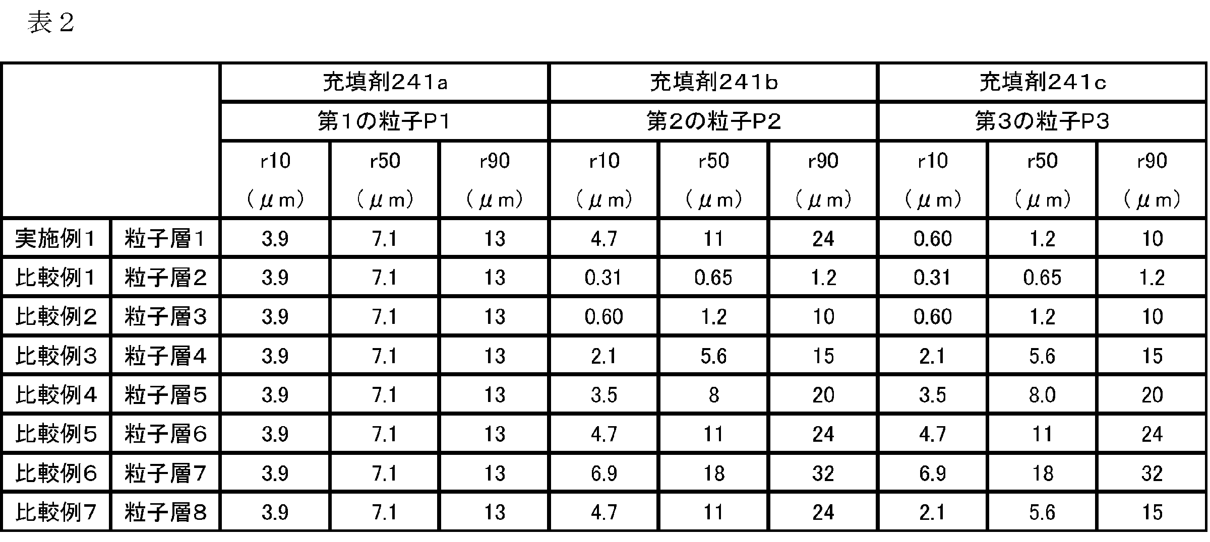
図23Bは、図23Aの拡大画像である。LBOは、粒径の大きい粒子群である粒子P2と、粒径の小さい粒子群である粒子P3を含む。
粒子P3である固体電解質粒子LBO(A2品)は、粒子P2よりも小さく、粒子層の上方部(第2の基材11bの反対側)に偏在して配置されていた。後述する方法により偏在の判定を行ったところ、粒子P3(固体電解質粒子LBO(A2品))のうち80個数%以上が、樹脂基材に接する側の反対側に偏在していた。これは上述したように、樹脂基材上の粘着部に粒子P1及び粒子P2を沈降させて、新たに表面に露出する粘着部に粒子P3を配置する第3、4工程(図1中、S103、S104)により実現する(図12A、図12B、図13及び図14)。
同様に、比較例1、3、4及び6においても、粒子P2及び粒子P3の粒径が同じであるため、実施例1のような粒子P3の偏在が確認できなかった。

実施例1の固体電解質粒子の一次粒子の平均円相当径reは1.1μmであり、個数基準でreの累積10%となる円相当径は0.48μmであった。すなわち、第2の粒子P2が電極基材における第一固体電解質粒子に相当し、第3の粒子P3が電極基材における第二固体電解質粒子に相当することが確認できた。
カバー率を算出するための画像は、SEM観察によって取得した。SEM観察は電子顕微鏡(S-4800:日立製作所製)により、電極基材上面(粒子層が形成されている側)を鉛直方向より撮影した。撮影したSEM画像の例を、図30に示す。撮影は以下の条件で行った。
検出器:ESB(反射電子像)
観察条件:加速電圧2kV
倍率:1000倍
フィルター:ESBフィルターに1500Vのバイアス印加
活物質粒子と固体電解質粒子の識別は、具体的には以下の方法で行う。樹脂基材をX線回折(XRD)等で分析し、樹脂基材を構成する物質の同定を行う。その後、活物質粒子及び固体電解質粒子に含まれる特有の元素をそれぞれSEM―EDXで検出し識別することができる。活物質粒子である第1の粒子P1としてLCOを用い、固体電解質粒子である第2の粒子P2及び第3の粒子P3としてLBOを用いた場合、CoをSEM-EDXで検出することにより活物質粒子を識別し、BをSEM-EDXで検出することにより固体電解質粒子を識別する。
画像処理にはopenCVを用い、解析はpythonにて行った。得られたSEM画像を平均明度100、標準偏差±30となるように正規化した。正規化した画像を、明度60を閾値として2値化し、すべての粒子が白画素で現わされる画像を用意した。用意した画像の例を図31に示す。画像を構成する全画素のうち、白画素で表されている割合を解析し、粒子のカバー率として算出した。例えば、図31におけるカバー率は96.3%である。
re及びraの算出、並びに粒子の偏在の判定においては、BIB-SEM画像を用いた。
以下にBIB-SEMの撮影条件について説明する。
基盤(Al箔)上に樹脂基材を3枚積層し、真空包装及び等方圧加圧したサンプルを準備した。サンプルをワイヤーソー(DWS3400/ワイヤー径170μm・ダイヤモンド径30μm)で切断し、切断面に対してArによるブロードイオンビームで断面加工(JEOL製SM-09010 Cross Section Polisher)した。断面加工の条件は、電圧6kV、電流150~200mAとした。BIB-SEM画像として、樹脂基材及び該粒子層の積層方向の断面を得て、断面観察を行う。
検出器:ESB(反射電子像)
観察条件:加速電圧3kV
倍率:1000倍
フィルター:ESBフィルターに1500Vのバイアス印加
活物質粒子と固体電解質粒子の識別は、上述の方法により行う。樹脂基材をX線回折(XRD)等で分析し、樹脂基材を構成する物質の同定を行う。その後、活物質粒子及び固体電解質粒子に含まれる特有の元素をそれぞれ上述の方法によりSEM―EDXで検出し、識別する。
BIB-SEM画像を用いた、re/raの算出方法を説明する。
<raの算出方法>
上述の条件により撮影したBIB-SEM画像から、活物質粒子を検出した。検出には、画像の境界検出法であるWatershed法を用いた。
はじめにBIB-SEM画像を平均明度100、標準偏差±30となるように正規化した。樹脂基材上の活物質粒子をカウントするために、上記正規化した画像から樹脂基材上の粒子層のみを表す画像を、画像中の全粒子を含むように切り出す。切り出した画像の例を、図33Aに示す。
切り出した画像を、明度120を閾値として2値化し、活物質粒子のみが白画素で表されている画像を得た。得られる画像の例を図33Bに示す。
次に、ノイズ除去の目的で、白画素で囲まれた領域を白で塗りつぶした後、モルフォロジー変換のオープニング処理をカーネルサイズ3×3画素にて行い、ノイズ除去後の画像を得た。ノイズ除去後の画像の例を図33Cに示す。
Watershed法を実行するために、画像中の確実に背景である部分、確実に前景(ここでは活物質粒子)である部分、どちらか判断できない部分を決定する。得られた画像に白部の膨張処理を行い、黒部分を背景として決定する。続いて、前景と背景の距離を求め、背景からの距離が20%以上離れている部分を確実に前景(活物質粒子)である部分とした。また、前景と背景の間を境界領域と定義し、Watershed法を適用することにより各粒子を検出した。粒子を検出した後の画像の例を図33Dに示す。例えば、図33Dからは、21個の粒子が検出される。
ra=(検出された粒子の画素数)×(SEM画像1画素当たりの長さ(μm))
算出した各活物質粒子の一次粒子の円相当径の、小粒径側から個数基準で累積50%の粒子の粒径を、活物質粒子の平均円相当径raとした。
例えば、図33Dにおいては、ra=64.7(画素)×0.04(μm)=2.6(μm)であった。
上述の方法によりBIB-SEM画像を正規化し、正規化した画像から樹脂基材上の粒子層の画像を切り出した。切り出した画像を、明度120を閾値として2値化し、活物質粒子のみが白画素で表されている画像を得た。得られる画像の例を図33Bに示す。
また、切り出した画像を、明度90を閾値として2値化し、固体電解質粒子及び活物質粒子の両方を白画素で表す画像を得た。得られる画像の例を、図34Aに示す。
固体電解質粒子及び活物質粒子の両方が白画素で表されている画像より、活物質粒子のみが白画素で表されている画像の白画素部を引くことにより、固体電解質粒子のみを白画素で表す画像が得られる。得られる画像の例を、図34Bに示す。
次に、ノイズ除去の目的で、白画素で囲まれた領域を白で塗りつぶした後、モルフォロジー変換のオープニング処理をカーネルサイズ3×3画素にて行い、ノイズ除去後の画像を得た。得られる画像の例を、図34Cに示す。
続いて、前景と背景の距離を求め、背景からの距離が10%以上離れている部分を確実に前景(固体電解質粒子)である部分とした。また、前景と背景の間を境界領域と定義した。境界領域を示す画像の例を、図34Eに示す。この画像に対しWatershed法を適用することにより、各粒子を検出した。粒子を検出した後の画像の例を図34Fに示す。例えば、図34Fからは、28個の粒子が検出される。
re=(検出された粒子の画素数)×(SEM画像1画素当たりの長さ(μm))
算出した各固体電解質粒子の一次粒子の円相当径の、小粒径側から個数基準で累積50%の粒子の粒径を、固体電解質粒子の平均円相当径reとした。
例えば、図34Fにおいては、ra=16.9(画素)×0.04(μm)=0.68μmであった。よって、図33D及び34Fに示される例においてはre/ra=0.68/2.6=0.26であり、0.01以上2.0以下となっていることが確認できる。
固体電解質粒子の偏在の判定は、以下の方法により行った。
以下に、偏在の基準線の決定方法、及び累積10%粒径に当たる固体電解質粒子の位置と基準線との関係を確認し、偏在を判定する方法を示す。BIB-SEMを用いた粒子層の断面観察において、偏在を判定する。BIB-SEM画像を得る手段は上述した通りである。
初めに、偏在の基準線を決定する。以下に一例として図35示すBIB-SEM画像における偏在の基準線決定方法を説明する。
偏在の基準線は、樹脂基材上の活物質粒子のz軸方向(樹脂基材及び粒子層の積層方向)における分布をとり、そのピーク位置を基準線とした。以下に手順を示す。
上述の方法により得たBIB-SEM画像を、平均明度100、標準偏差±30となるように正規化した後、明度の閾値120にて2値化した。このとき、白画素で表されている粒子が活物質粒子である。z軸方向に並んでいる各ラスタの白画素数をカウントすることで、樹脂基材上の粒子層における活物質粒子の樹脂基材及び粒子層の積層方向の分布が得られる。樹脂基材上の粒子層において、活物質粒子の分布がピークとなる位置を偏在の基準線とした。すなわち、z軸方向において活物質粒子の分布がピークとなる位置で、z軸方向に垂直な基準線を引く。
BIB-SEM画像及び活物質粒子の分布のピークの例を、図35に示す。図35は、電極基材を3枚積層した電極基材積層体の断面のBIB-SEM画像を示す図である。図35の下側(z軸の基点側)から、樹脂基材、粒子層の順に形成された電極基材が、3枚積層された様子が示されている。基準線は、それぞれの電極基材において活物質粒子の分布がピークとなる位置を特定し定める。例えば、図35では、右側(活物質分布)のピークと点線が重なっている位置での点線が基準線を示す。
次に、BIB-SEM画像における、固体電解質粒子の偏在の判定方法を説明する。
上述の方法により、SEM画像上において樹脂基材上の固体電解質粒子を検出し、円相当径を算出した。得られた固体電解質粒子の一次粒子の円相当径の分布において、小粒径側から個数基準で累積10%粒径以下の粒子を抽出し、第二固体電解質粒子を特定した。
特定した第二固体電解質粒子の各粒子において、樹脂基材の表面からのz軸方向における最短距離を最小値min、最長距離を最大値maxとする。なお、最長距離は、z軸方向において樹脂基材の表面から第二固体電解質粒子の最も遠い部分の位置である。そしてminとmaxの平均値を第二固体電解質粒子の中央の位置として求め、これを第二固体電解質粒子の位置とした。
例えば、図36においては、図中に示す19(円で囲まれた部分の中心)が第二固体電解質粒子中央の位置、すなわち粒子の位置である。また、図中に示す破線が、上述の方法により決定した基準線である。
次に、各画像において、80個数%以上の第二固体電解質粒子が基準線よりも樹脂基材と接触する側又は樹脂基材側の反対側に位置するかを確認する。5枚の画像中のすべての第二固体電解質粒子計500個に対して、1回の判定を行う。
上述の通り、第二固体電解質粒子の位置は、粒子の中央の位置をもとに判断する。すなわち、第二固体電解質粒子のうち、80個数%以上の第二固体電解質粒子の中央の位置が基準線よりも樹脂基材側又は樹脂基材と反対側に位置している場合、第二固体電解質粒子が偏在していると判断する。例えば、図36においては、80個数%以上の第二固体電解質粒子が、基準線よりも樹脂基材の遠方に存在することを確認できる。
同定された第二固体電解質粒子のうち、80個数%以上が、基準線よりも樹脂基材側又は樹脂基材と反対側に位置している場合に、第二固体電解質粒子が偏在していると判断する。
また、本開示では、電極基材は、樹脂基材、粒子層及び樹脂基材がこの順に積層された態様であってもよい。この場合も、上記と同様、一方を樹脂基材側とし、他方を反対側として、上述の方法により偏在を判定することができる。
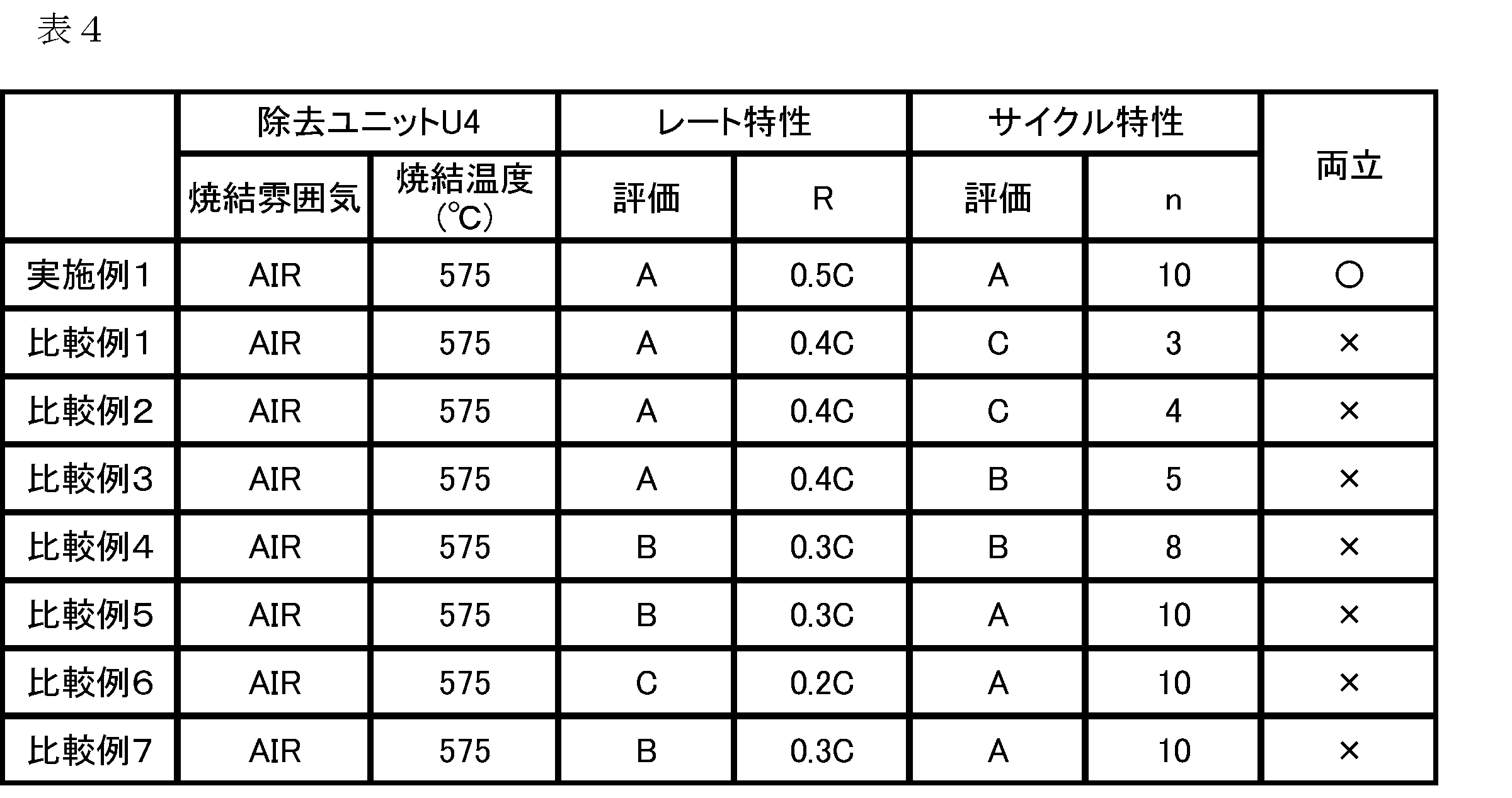
<レート特性>
電極基材の単位面積当たりの活物質粒子質量M(g/cm2)から、電極の活物質粒子質量(M×積層枚数×電極面積(cm2))を算出し、電流レートを決定する。
単位面積当たりの活物質粒子質量Mは、以下のようにして求める。
第1の充填装置により第1の粒子P1を充填した後の第1の基材11aの重量を測定する。次に、上述の第1の基材11a上の粒子P1を第2の基材11bへ転写した後の、第1の基材11aの重量を測定する。その差分を測定し、第1の基材11aの面積(凹凸領域の面積)で割ることで単位面積当たりの活物質粒子質量Mを算出できる。本開示においては、上記の方法により単位面積当たりの活物質粒子質量Mを算出した。
別の算出方法として、ICP発光分光分析法を用いる方法もある。予め上述の方法等で、単位面積当たりの活物質粒子質量M(g/cm2)が明らかになっている3水準の第1の基材11aを準備する。これらの第1の基材11aをマイクロウェーブによる酸分解(ETHOS PRO)で溶解して、酸分解液を超純水で希釈してICP-AES測定(CIROS CCD)を行い、Co元素の定量化を行う。得られた元素濃度に対する単位面積当たりの活物質粒子質量M(g/cm2)の検量線が得られる。検量線より活物質粒子質量M(g/cm2)を求めることができる。
なお、LCOの実容量は、120mAh/gとし、カットオフ電圧(対Li)は、4.2V(充電)/2.6V(放電)とした。充放電装置(バイオロジック社製)により、各レートで充放電測定(定電流モード)を行い、容量維持率(放電容量/充電容量×100%)を測定する。容量維持率が80%以上のレートの最大値Rを求め、下記の評価基準で評価した。
A:R≧0.4C
B:0.4C>R≧0.3C
C:0.3C>R
上記のレート特性評価で求めたレートRでサイクル評価(定電流モードの繰り返し充放電測定)を行った。初期の容量維持率に対して、80%以下の容量になるまで繰り返し充放電測定を行い、その回数nを求め、下記の評価基準で評価した。
A:n≧10
B:10>n≧5
C:5>n
上述の通り、実施例1の電極基材11は、粒子P3が樹脂基材側と反対側の位置に偏在し、緻密な領域を形成している。一方、基材側には、粒子P1、P2の粒子間に空隙(例えば図27のSP部)が一様に分布している。焼結により基材が除去されても、各基材の緻密な領域と一様な空隙は維持され、図27に示される構造が実現されていると考えられる。
図29は、比較例5の電極基材6を用いて製造した電極断面のBIB-SEM画像である。LCOの周囲に空隙が確認できるが、粒子層全体に空隙が多く、緻密性が低い。
第2の粒子P2の種類、第3の粒子P3の種類、及び第1の基材11a上の凹凸パターン111aの凸部のピッチsを表5に示すように変更した以外は粒子層1と同様の条件にて、粒子層9~13を形成し、電極基材9~13を得た。得られた電極基材9~13を実施例2~6とした。
表5は、実施例1~6で使用した充填剤241a、241b、241cと第1の基材11a上の凹凸パターン111aを示す。

表中、粒子の質量%は、各充填剤中における各粒子の質量%を示す。
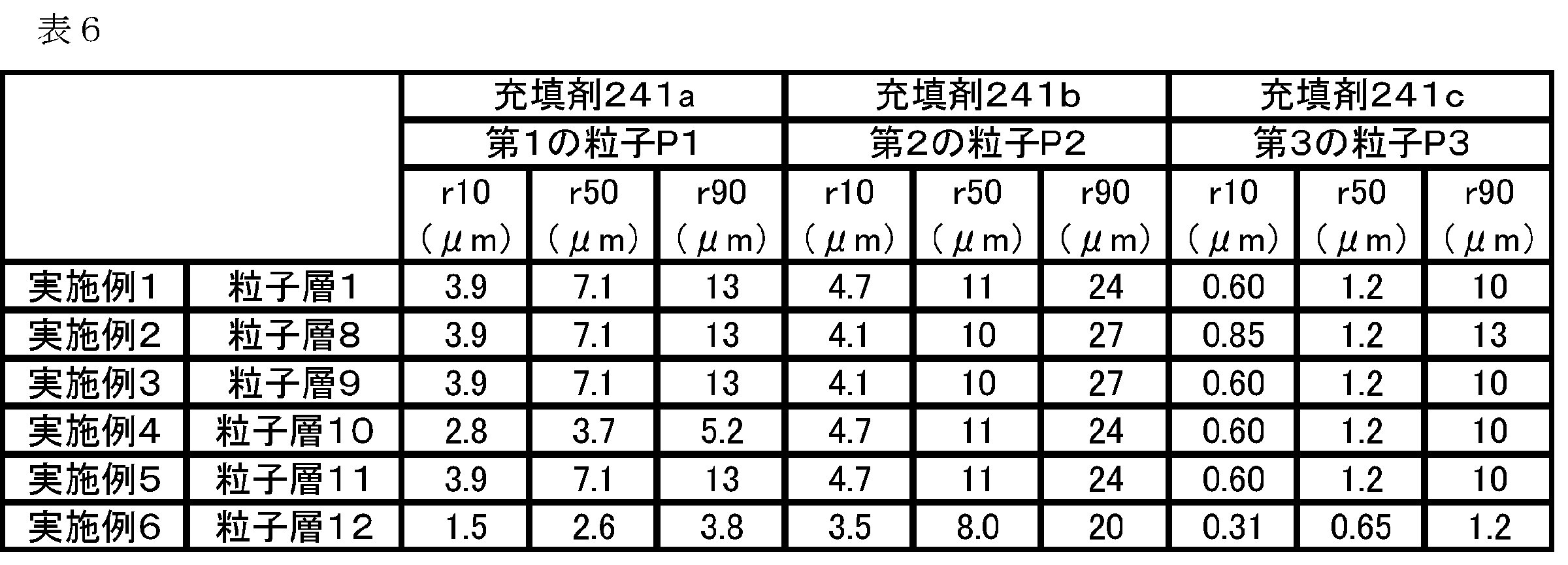
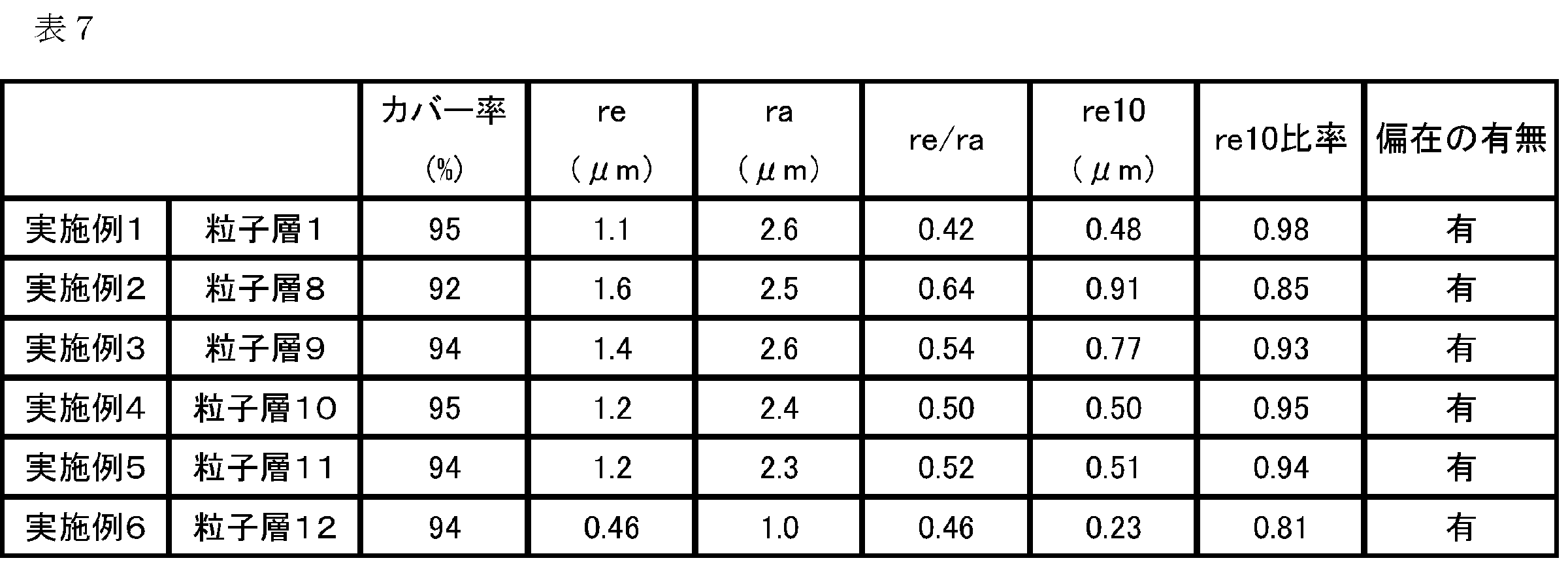
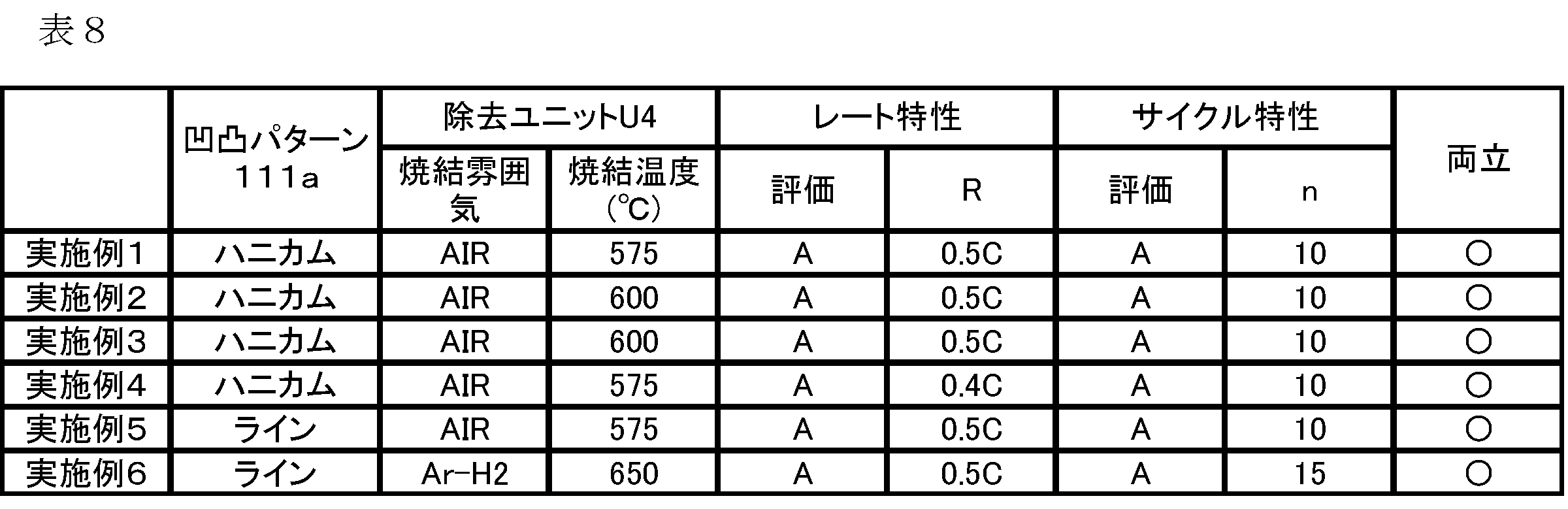
本願は、2023年6月14日提出の日本国特許出願特願2023-097669を基礎として優先権を主張するものであり、その記載内容の全てをここに援用する。
Claims (17)
- 電極の製造に用いられる電極基材であって、
該電極基材は、
樹脂基材と、該樹脂基材上の活物質粒子及び固体電解質粒子を含み、
該樹脂基材上に、該活物質粒子及び該固体電解質粒子を含む粒子層が形成され、
該活物質粒子の一次粒子の円相当径の分布から算出される個数基準の累積50%粒径を該活物質粒子の平均円相当径raとし、該固体電解質粒子の一次粒子の円相当径の分布から算出される個数基準の累積50%粒径を該固体電解質粒子の平均円相当径reとしたとき、
該平均円相当径raに対する、該平均円相当径reの比の値(re/ra)が0.01以上2.0以下であり、
該固体電解質粒子のうち、
該固体電解質粒子の一次粒子の円相当径の分布において小粒径側から個数基準で累積10%粒径を超える粒径の粒子を第一固体電解質粒子とし、
該累積10%粒径以下の粒子を第二固体電解質粒子としたとき、
該粒子層において、
該活物質粒子と、該第一固体電解質粒子とが隣接して配置され、
該粒子層の断面観察において、該第二固体電解質粒子のうち80個数%以上が、基準線に対して、該粒子層の該樹脂基材と接触する側、又は該樹脂基材側の反対側に偏在して配置され、
該基準線は、該粒子層における該活物質粒子の該樹脂基材及び該粒子層の積層方向の分布のピーク位置を示す、
ことを特徴とする、電極基材。 - 前記第一固体電解質粒子が、Li-B酸化物系の電解質粒子を含み、
前記活物質粒子が、Li-Co酸化物系の活物質粒子を含む、請求項1に記載の電極基材。 - 前記第二固体電解質粒子が、Li-B酸化物系の電解質粒子を含む、請求項1又は2に記載の電極基材。
- 前記第一固体電解質粒子が、Li-B酸化物系の電解質粒子を含み、
前記活物質粒子が、Li-PO4酸化物系の活物質粒子を含む、請求項1に記載の電極基材。 - 前記第二固体電解質粒子が、Li-B酸化物系の電解質粒子を含む、請求項1又は4に記載の電極基材。
- 前記樹脂基材の表面における、前記活物質粒子及び前記固体電解質粒子によるカバー率が、60%以上99%以下である、請求項1~5のいずれか一項に記載の電極基材。
- 請求項1~6のいずれか一項に記載の電極基材を複数積層した、電極基材積層体。
- 請求項7に記載の電極基材積層体であって、
該電極基材積層体の断面において、前記樹脂基材と前記粒子層とが交互に存在する、電極基材積層体。 - 二次電池の電極であって、請求項1~6のいずれか一項に記載の電極基材の焼結体である電極。
- 前記固体電解質粒子が、Li-B酸化物系の固体電解質粒子を含み、
前記活物質粒子が、Li-Co酸化物系の活物質粒子を含む、請求項9に記載の電極。 - 請求項9又は10に記載の電極と、該電極に隣接する電解質層とを含む二次電池。
- 電極の製造に用いられる請求項1~6のいずれか一項に記載の電極基材の製造方法であって、
該製造方法は、
粘着部を備えた前記樹脂基材を準備する工程と、
該粘着部の表面に、前記活物質粒子及び前記第一固体電解質粒子を配置する工程と、
該粘着部の表面に配置された前記第一固体電解質粒子及び前記活物質粒子を該粘着部に沈降させる粒子沈降工程と、
沈降させた前記第一電解質粒子及び前記活物質粒子の間の該粘着部に、第二固体電解質粒子を配置する工程と、を有する電極基材の製造方法。 - 電極の製造に用いられる電極基材の製造方法であって、
該電極基材は、
該樹脂基材上の活物質粒子及び固体電解質粒子を含み、
該樹脂基材上に、該活物質粒子と該固体電解質粒子とを含む粒子層が形成され、
該活物質粒子の一次粒子の円相当径の分布から算出される個数基準の累積50%粒径を該活物質粒子の平均円相当径raとし、該固体電解質粒子の一次粒子の円相当径の分布から算出される個数基準の累積50%粒径を該固体電解質粒子の平均円相当径reとしたとき、
該平均円相当径raに対する、該平均円相当径reの比の値(re/ra)が0.01以上2.0以下であり、
該固体電解質粒子が、固体電解質粒子P2と固体電解質粒子P3を含み、
該固体電解質粒子P2の一次粒子の体積基準の粒度分布における累積50%粒径(r50)は、固体電解質粒子P3の一次粒子の体積基準の粒度分布における累積50%粒径(r50)よりも大きく、
該製造方法は、
表面に粘着部を備えた該樹脂基材を準備する工程と、
該粘着部の表面に、該活物質粒子及び該固体電解質粒子P2を隣接して配置する工程と、
該粘着部の表面に配置された該固体電解質粒子P2及び該活物質粒子を該粘着部に沈降させる粒子沈降工程と、
沈降させた該固体電解質粒子P2及び該活物質粒子の間の該粘着部に、該固体電解質粒子P3を配置する工程と、
を有する電極基材の製造方法。 - 電極の製造方法であって、
請求項1~6のいずれか一項に記載の電極基材を複数積層し、積層体を成形する工程と、
該積層体から前記樹脂基材を除去し、立体物を得る工程と、
前記立体物を加圧し、電極を得る工程と、を有する電極の製造方法。 - 二次電池の製造方法であって、
該製造方法は、
請求項14に記載の電極の製造方法により電極を準備する工程と、
該電極、集電体及び電解質を積層する工程と、
を有する二次電池の製造方法。 - 二次電池の製造方法であって、
該製造方法は、
請求項14に記載の電極の製造方法により電極を準備する工程と、
該電極に隣接する固体電解質を設ける工程と、を有する二次電池の製造方法。 - 二次電池の製造方法であって、
該製造方法は、請求項9又は10に記載の電極及び該電極に隣接する固体電解質を一括して設ける工程を有する二次電池の製造方法。
Priority Applications (3)
| Application Number | Priority Date | Filing Date | Title |
|---|---|---|---|
| CN202480038958.1A CN121285878A (zh) | 2023-06-14 | 2024-06-12 | 电极基材、电极基材层叠体、电极、二次电池及其制造方法 |
| EP24823407.2A EP4730425A1 (en) | 2023-06-14 | 2024-06-12 | Electrode base material, electrode base material laminate, electrode, secondary battery, and method for manufacturing same |
| US19/411,474 US20260094865A1 (en) | 2023-06-14 | 2025-12-08 | Electrode base material, electrode base material laminate, electrode, secondary battery, and methods for manufacturing same |
Applications Claiming Priority (2)
| Application Number | Priority Date | Filing Date | Title |
|---|---|---|---|
| JP2023-097669 | 2023-06-14 | ||
| JP2023097669A JP2024179111A (ja) | 2023-06-14 | 2023-06-14 | 電極基材、電極基材積層体、電極及び二次電池、並びにその製造方法 |
Related Child Applications (1)
| Application Number | Title | Priority Date | Filing Date |
|---|---|---|---|
| US19/411,474 Continuation US20260094865A1 (en) | 2023-06-14 | 2025-12-08 | Electrode base material, electrode base material laminate, electrode, secondary battery, and methods for manufacturing same |
Publications (1)
| Publication Number | Publication Date |
|---|---|
| WO2024257792A1 true WO2024257792A1 (ja) | 2024-12-19 |
Family
ID=93852155
Family Applications (1)
| Application Number | Title | Priority Date | Filing Date |
|---|---|---|---|
| PCT/JP2024/021328 Ceased WO2024257792A1 (ja) | 2023-06-14 | 2024-06-12 | 電極基材、電極基材積層体、電極及び二次電池、並びにその製造方法 |
Country Status (5)
| Country | Link |
|---|---|
| US (1) | US20260094865A1 (ja) |
| EP (1) | EP4730425A1 (ja) |
| JP (1) | JP2024179111A (ja) |
| CN (1) | CN121285878A (ja) |
| WO (1) | WO2024257792A1 (ja) |
Citations (6)
| Publication number | Priority date | Publication date | Assignee | Title |
|---|---|---|---|---|
| JP2019040709A (ja) * | 2017-08-24 | 2019-03-14 | 株式会社日立製作所 | 全固体リチウムイオン二次電池およびその製造方法 |
| JP2019137061A (ja) * | 2018-02-14 | 2019-08-22 | キヤノン株式会社 | 立体物の製造方法、および、積層造形システム |
| JP2020198301A (ja) | 2019-05-31 | 2020-12-10 | キヤノン株式会社 | 活物質、活物質の製造方法、電極、及び電池 |
| JP2021002482A (ja) | 2019-06-21 | 2021-01-07 | 太陽誘電株式会社 | 全固体電池 |
| JP2022142259A (ja) * | 2021-03-16 | 2022-09-30 | 東洋紡株式会社 | 全固体電池材料製造用の離型フィルム |
| JP2023097669A (ja) | 2021-12-28 | 2023-07-10 | 株式会社サンセイアールアンドディ | 遊技機 |
-
2023
- 2023-06-14 JP JP2023097669A patent/JP2024179111A/ja active Pending
-
2024
- 2024-06-12 EP EP24823407.2A patent/EP4730425A1/en active Pending
- 2024-06-12 CN CN202480038958.1A patent/CN121285878A/zh active Pending
- 2024-06-12 WO PCT/JP2024/021328 patent/WO2024257792A1/ja not_active Ceased
-
2025
- 2025-12-08 US US19/411,474 patent/US20260094865A1/en active Pending
Patent Citations (6)
| Publication number | Priority date | Publication date | Assignee | Title |
|---|---|---|---|---|
| JP2019040709A (ja) * | 2017-08-24 | 2019-03-14 | 株式会社日立製作所 | 全固体リチウムイオン二次電池およびその製造方法 |
| JP2019137061A (ja) * | 2018-02-14 | 2019-08-22 | キヤノン株式会社 | 立体物の製造方法、および、積層造形システム |
| JP2020198301A (ja) | 2019-05-31 | 2020-12-10 | キヤノン株式会社 | 活物質、活物質の製造方法、電極、及び電池 |
| JP2021002482A (ja) | 2019-06-21 | 2021-01-07 | 太陽誘電株式会社 | 全固体電池 |
| JP2022142259A (ja) * | 2021-03-16 | 2022-09-30 | 東洋紡株式会社 | 全固体電池材料製造用の離型フィルム |
| JP2023097669A (ja) | 2021-12-28 | 2023-07-10 | 株式会社サンセイアールアンドディ | 遊技機 |
Also Published As
| Publication number | Publication date |
|---|---|
| JP2024179111A (ja) | 2024-12-26 |
| EP4730425A1 (en) | 2026-04-22 |
| CN121285878A (zh) | 2026-01-06 |
| US20260094865A1 (en) | 2026-04-02 |
Similar Documents
| Publication | Publication Date | Title |
|---|---|---|
| JP7809851B2 (ja) | 材料シート、積層体、材料シートの製造方法および積層体の製造方法 | |
| JP7301548B2 (ja) | 電極シートの製造方法、および、固体電解質シートの製造方法 | |
| JP7690262B2 (ja) | 活物質、活物質の製造方法、正極、及び、二次電池 | |
| US20220085359A1 (en) | Active material, method for producing active material, electrode and battery | |
| CN114128007B (zh) | 电极用成型体的制造方法 | |
| CN115000350B (zh) | 二次电池用电极的制造方法和该电极 | |
| JP6797241B2 (ja) | 電極部材、全固体電池、電極部材用粉末、電極部材の製造方法及び全固体電池の製造方法 | |
| WO2025173736A1 (ja) | 材料層の製造方法及び固体電池の電極の製造方法 | |
| JP2024179111A (ja) | 電極基材、電極基材積層体、電極及び二次電池、並びにその製造方法 | |
| WO2025041819A1 (ja) | 電極基材、電極基材積層体、電極及び二次電池、並びにその製造方法 | |
| EP4503235A1 (en) | All-solid-state secondary battery | |
| WO2026105860A1 (ja) | 電極前駆体及び二次電池並びにその製造方法 | |
| WO2025164590A1 (ja) | 電極複合体及び電池、並びにその製造方法 | |
| CN119631192A (zh) | 片状电极用成型体的制造方法 | |
| JP2026077643A (ja) | 材料層の製造方法、立体物の製造方法、材料層、積層体、材料層形成装置、および、積層造形システム | |
| JP2025041222A (ja) | 固体電解質基材、固体電解質、二次電池及び固体電解質基材の製造方法 | |
| CN119604986A (zh) | 片状电极用成型体的制造方法 | |
| CN119604987A (zh) | 片状电极用成型体的制造方法 |
Legal Events
| Date | Code | Title | Description |
|---|---|---|---|
| 121 | Ep: the epo has been informed by wipo that ep was designated in this application |
Ref document number: 24823407 Country of ref document: EP Kind code of ref document: A1 |
|
| WWE | Wipo information: entry into national phase |
Ref document number: 2024823407 Country of ref document: EP |
|
| NENP | Non-entry into the national phase |
Ref country code: DE |
|
| ENP | Entry into the national phase |
Ref document number: 2024823407 Country of ref document: EP Effective date: 20260114 |
|
| ENP | Entry into the national phase |
Ref document number: 2024823407 Country of ref document: EP Effective date: 20260114 |
|
| ENP | Entry into the national phase |
Ref document number: 2024823407 Country of ref document: EP Effective date: 20260114 |
|
| ENP | Entry into the national phase |
Ref document number: 2024823407 Country of ref document: EP Effective date: 20260114 |
|
| WWP | Wipo information: published in national office |
Ref document number: 2024823407 Country of ref document: EP |