WO2024257717A1 - ガス製造装置の停止方法、並びに、酸素ガス及び水素ガスの製造方法 - Google Patents
ガス製造装置の停止方法、並びに、酸素ガス及び水素ガスの製造方法 Download PDFInfo
- Publication number
- WO2024257717A1 WO2024257717A1 PCT/JP2024/021012 JP2024021012W WO2024257717A1 WO 2024257717 A1 WO2024257717 A1 WO 2024257717A1 JP 2024021012 W JP2024021012 W JP 2024021012W WO 2024257717 A1 WO2024257717 A1 WO 2024257717A1
- Authority
- WO
- WIPO (PCT)
- Prior art keywords
- gas
- electrolyte
- cathode
- anode
- chamber
- Prior art date
- Legal status (The legal status is an assumption and is not a legal conclusion. Google has not performed a legal analysis and makes no representation as to the accuracy of the status listed.)
- Ceased
Links
Images



Classifications
-
- C—CHEMISTRY; METALLURGY
- C01—INORGANIC CHEMISTRY
- C01B—NON-METALLIC ELEMENTS; COMPOUNDS THEREOF; METALLOIDS OR COMPOUNDS THEREOF NOT COVERED BY SUBCLASS C01C
- C01B13/00—Oxygen; Ozone; Oxides or hydroxides in general
- C01B13/02—Preparation of oxygen
-
- C—CHEMISTRY; METALLURGY
- C01—INORGANIC CHEMISTRY
- C01B—NON-METALLIC ELEMENTS; COMPOUNDS THEREOF; METALLOIDS OR COMPOUNDS THEREOF NOT COVERED BY SUBCLASS C01C
- C01B3/00—Hydrogen; Gaseous mixtures containing hydrogen; Separation of hydrogen from mixtures containing it; Purification of hydrogen; Reversible storage of hydrogen
- C01B3/02—Production of hydrogen; Production of gaseous mixtures containing hydrogen
-
- C—CHEMISTRY; METALLURGY
- C25—ELECTROLYTIC OR ELECTROPHORETIC PROCESSES; APPARATUS THEREFOR
- C25B—ELECTROLYTIC OR ELECTROPHORETIC PROCESSES FOR THE PRODUCTION OF COMPOUNDS OR NON-METALS; APPARATUS THEREFOR
- C25B1/00—Electrolytic production of inorganic compounds or non-metals
- C25B1/01—Products
- C25B1/02—Hydrogen or oxygen
- C25B1/04—Hydrogen or oxygen by electrolysis of water
-
- C—CHEMISTRY; METALLURGY
- C25—ELECTROLYTIC OR ELECTROPHORETIC PROCESSES; APPARATUS THEREFOR
- C25B—ELECTROLYTIC OR ELECTROPHORETIC PROCESSES FOR THE PRODUCTION OF COMPOUNDS OR NON-METALS; APPARATUS THEREFOR
- C25B15/00—Operating or servicing cells
-
- C—CHEMISTRY; METALLURGY
- C25—ELECTROLYTIC OR ELECTROPHORETIC PROCESSES; APPARATUS THEREFOR
- C25B—ELECTROLYTIC OR ELECTROPHORETIC PROCESSES FOR THE PRODUCTION OF COMPOUNDS OR NON-METALS; APPARATUS THEREFOR
- C25B15/00—Operating or servicing cells
- C25B15/02—Process control or regulation
-
- C—CHEMISTRY; METALLURGY
- C25—ELECTROLYTIC OR ELECTROPHORETIC PROCESSES; APPARATUS THEREFOR
- C25B—ELECTROLYTIC OR ELECTROPHORETIC PROCESSES FOR THE PRODUCTION OF COMPOUNDS OR NON-METALS; APPARATUS THEREFOR
- C25B15/00—Operating or servicing cells
- C25B15/08—Supplying or removing reactants or electrolytes; Regeneration of electrolytes
-
- C—CHEMISTRY; METALLURGY
- C25—ELECTROLYTIC OR ELECTROPHORETIC PROCESSES; APPARATUS THEREFOR
- C25B—ELECTROLYTIC OR ELECTROPHORETIC PROCESSES FOR THE PRODUCTION OF COMPOUNDS OR NON-METALS; APPARATUS THEREFOR
- C25B9/00—Cells or assemblies of cells; Constructional parts of cells; Assemblies of constructional parts, e.g. electrode-diaphragm assemblies; Process-related cell features
-
- C—CHEMISTRY; METALLURGY
- C25—ELECTROLYTIC OR ELECTROPHORETIC PROCESSES; APPARATUS THEREFOR
- C25B—ELECTROLYTIC OR ELECTROPHORETIC PROCESSES FOR THE PRODUCTION OF COMPOUNDS OR NON-METALS; APPARATUS THEREFOR
- C25B9/00—Cells or assemblies of cells; Constructional parts of cells; Assemblies of constructional parts, e.g. electrode-diaphragm assemblies; Process-related cell features
- C25B9/05—Pressure cells
-
- C—CHEMISTRY; METALLURGY
- C25—ELECTROLYTIC OR ELECTROPHORETIC PROCESSES; APPARATUS THEREFOR
- C25B—ELECTROLYTIC OR ELECTROPHORETIC PROCESSES FOR THE PRODUCTION OF COMPOUNDS OR NON-METALS; APPARATUS THEREFOR
- C25B9/00—Cells or assemblies of cells; Constructional parts of cells; Assemblies of constructional parts, e.g. electrode-diaphragm assemblies; Process-related cell features
- C25B9/17—Cells comprising dimensionally-stable non-movable electrodes; Assemblies of constructional parts thereof
- C25B9/19—Cells comprising dimensionally-stable non-movable electrodes; Assemblies of constructional parts thereof with diaphragms
-
- Y—GENERAL TAGGING OF NEW TECHNOLOGICAL DEVELOPMENTS; GENERAL TAGGING OF CROSS-SECTIONAL TECHNOLOGIES SPANNING OVER SEVERAL SECTIONS OF THE IPC; TECHNICAL SUBJECTS COVERED BY FORMER USPC CROSS-REFERENCE ART COLLECTIONS [XRACs] AND DIGESTS
- Y02—TECHNOLOGIES OR APPLICATIONS FOR MITIGATION OR ADAPTATION AGAINST CLIMATE CHANGE
- Y02E—REDUCTION OF GREENHOUSE GAS [GHG] EMISSIONS, RELATED TO ENERGY GENERATION, TRANSMISSION OR DISTRIBUTION
- Y02E60/00—Enabling technologies; Technologies with a potential or indirect contribution to GHG emissions mitigation
- Y02E60/30—Hydrogen technology
- Y02E60/36—Hydrogen production from non-carbon containing sources, e.g. by water electrolysis
Definitions
- the present invention relates to a method for shutting down a gas production device and a method for producing oxygen gas and hydrogen gas.
- Alkaline water electrolysis is known as a method for producing hydrogen gas and oxygen gas.
- a basic aqueous solution (alkaline water) containing dissolved alkali metal hydroxides (e.g. NaOH, KOH, etc.) is used as the electrolyte to electrolyze water, generating hydrogen gas from the cathode and oxygen gas from the anode.
- an electrolytic cell for alkaline water electrolysis has an anode chamber and a cathode chamber separated by an ion-permeable diaphragm, and electrolysis is carried out while circulating electrolyte in each of the anode and cathode chambers.
- the electrolyte recovered from each electrode chamber is temporarily collected and stored in a circulation tank, and the electrolyte stored in the circulation tank is then supplied again to each electrode chamber.
- the anode reaction is 2OH ⁇ ⁇ (1/2)O 2 ⁇ +H 2 O+2e ⁇ ...(1)
- the cathode reaction is 2H 2 O + 2e - ⁇ H 2 ⁇ + 2OH - (2) Therefore, in the alkaline water electrolysis process, although water is consumed overall, water is consumed in the cathode reaction while water is produced in the anode reaction, so that a liquid level difference occurs between the anode side circulation tank and the cathode side circulation tank as the electrolysis reaction progresses.
- OH - ions are consumed in the anode reaction and OH - ions are produced in the cathode reaction, so that ions move through the diaphragm to maintain charge neutrality between the anode chamber and the cathode chamber, but not all of the OH - ions produced in the cathode reaction move from the cathode chamber to the anode chamber.
- Patent Document 1 proposes a method in which an electrolyte exchange device is provided between the anode side circulation tank and the cathode side circulation tank, and a portion of the electrolyte from one tank is transferred to the other tank, thereby eliminating the difference in electrolyte concentration and the difference in liquid level between the anode side circulation tank and the cathode side circulation tank.
- oxygen gas is dissolved in the electrolyte on the anode side, and when this electrolyte is moved to the cathode side, oxygen gas will be dissolved in the electrolyte on the cathode side along with hydrogen gas, the main gas.
- hydrogen gas is dissolved in the electrolyte on the cathode side, and when this electrolyte is moved to the anode side, hydrogen gas will be dissolved in the electrolyte on the anode side along with oxygen gas, the main gas.
- the amount of gas dissolved in the electrolyte increases as the pressure increases. Therefore, the amount of gas dissolved in the electrolyte increases particularly in a high-pressure alkaline water electrolysis device that performs electrolysis under pressurized conditions.
- a high-pressure alkaline water electrolysis device is operated by controlling the pressure and temperature at constant values, the amount of gas dissolved in the electrolyte is maintained at a constant level.
- the power source of the water electrolysis device is solar power generation
- hydrogen production is stopped in the evening because there is no power generation at night, and the device is restarted the next morning, and hydrogen production is started again in a repeated cycle.
- the above-mentioned exchange of the electrolyte between the anode side and the cathode side may cause the problem of coexistence of gases in the gas phase not only in the case of mutual exchange but also in the case of exchange of only one side (only from the anode side to the cathode side, or only from the cathode side to the anode side).
- both electrolytes may be mixed in a mixing tank and the mixed electrolyte may be returned to the anode chamber and the cathode chamber again.
- the problem of coexistence of gases in the gas phase may occur.
- the present invention aims to provide a method for stopping a gas production device that prevents the problem of gas coexistence in the gas phase region of each circulation tank, etc., even when the water electrolysis device is temporarily stopped while electrolyte exchange is being performed between the anode and cathode sides, or when alkaline water electrolysis is performed under pressurized conditions, and that also makes it possible to prevent the gas composition from reaching the explosion limit.
- a method for shutting down a gas production apparatus comprising the steps of: (a) shutting down the operation of the gas production apparatus by a procedure including the following steps (a) to (c): (a) reducing the pressure within the apparatus; (b) continuing gas production under reduced pressure; (c) shutting down the gas production equipment;
- an anode-side electrolyte circulation system is formed so that the electrolyte flowing out of the anode chamber flows back into the anode chamber during operation of the gas production apparatus, and a cathode-side electrolyte circulation system is formed so that the electrolyte flowing out of the cathode chamber flows back into the cathode chamber, a part of the electrolyte flowing out from the anode chamber is transferred to the cathode-side electrolyte circulation system, and/or a part of the electrolyte flowing out from the cathode chamber is transferred to the anode-side electrolyte circulation system,
- [3] A method for shutting down a gas production apparatus according to [1] or [2], wherein the pressurized conditions are conditions in which the pressure inside the anode chamber, the cathode chamber, or both of them is maintained at a pressure higher than atmospheric pressure by 20 kPa or more.
- the anode-side circulation system includes an anode-side circulation tank that stores an electrolytic solution circulating through the anode-side circulation system
- the cathode-side circulation system includes a cathode-side circulation tank that stores an electrolytic solution circulating through the cathode-side circulation system
- the method for shutting down a gas production apparatus according to any one of [1] to [3], wherein the step (b) further comprises: introducing a part of the oxygen gas generated on the anode side into the electrolytic solution in the anode-side circulation tank to release the dissolved gas in the electrolytic solution; and/or introducing a part of the hydrogen gas generated on the cathode side into the electrolytic solution in the cathode-side circulation tank to release the dissolved gas in the electrolytic solution.
- a method for producing oxygen gas and hydrogen gas comprising a step of stopping the operation of a gas production apparatus by a method for stopping a gas production apparatus according to any one of [1] to [4].
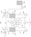
- FIG. 1 is a schematic diagram showing an embodiment 100a of a gas production apparatus to which the shut-down method of the present invention can be applied.
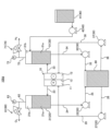
- FIG. 1 is a schematic diagram showing an embodiment 100b of a gas production apparatus to which the shutdown method of the present invention can be applied.
- FIG. 1 is a schematic diagram showing an embodiment 100c of a gas production apparatus to which the shut-down method of the present invention can be applied.
- FIG. 1 is a schematic diagram showing an embodiment 100d of a gas production apparatus to which the shutdown method of the present invention can be applied.
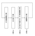
- FIG. 2 is a flow chart showing each step of the stopping method of the present invention.
- FIG. 4 is a flow chart showing a control example of a stopping method of the present invention.
- a gas production apparatus 100a used in the method for shutting down a gas production apparatus of the present invention will be described with reference to Fig. 1.
- the gas production apparatus 100a shown in Fig. 1 is merely one embodiment.
- the gas production apparatus 100a uses an alkaline aqueous solution as an electrolyte and produces oxygen gas and hydrogen gas by electrolysis of the alkaline aqueous solution.
- the gas production device 100a includes an electrolytic cell 10, a first electrolyte circulation system 20, a second electrolyte circulation system 30, a pure water supply system 40, a first gas recovery line 60, and a second gas recovery line 70.
- the arrows indicate the direction of material flow.
- the electrolytic cell 10 is equipped with an anode chamber 11 that houses an anode and generates oxygen gas, a cathode chamber 12 that houses a cathode and generates hydrogen gas, and an ion-permeable diaphragm 13 that separates the anode chamber 11 from the cathode chamber 12.
- an electrolytic cell 10 any electrolytic cell of the type conventionally used in alkaline water electrolysis devices can be used without any particular restrictions.
- the first electrolyte circulation system 20 includes a first circulation tank 21 that receives and stores the first electrolyte flowing out from the anode chamber 11, and a first circulation pump 22 that supplies the first electrolyte stored in the first circulation tank 21 to the anode chamber 11. Inside the first circulation tank 21, there is a liquid phase region 21a occupied by the stored first electrolyte, and a gas phase region 21b which is the space above the liquid phase region 21a.
- the first electrolyte circulation system 20 further includes a pipe 23 that guides the first electrolyte and anode gas flowing out from the anode chamber 11 to the first circulation tank 21, a pipe 24 that guides the first electrolyte from the liquid phase region 21a of the first circulation tank 21 to the first circulation pump 22, and a pipe 25 that guides the first electrolyte delivered from the first circulation pump 22 to the anode chamber 11.
- the first gas-liquid mixture flowing out from the anode chamber 11 is guided to the first circulation tank 21 through the pipe 23, and inside the first circulation tank 21, the first electrolytic solution is separated into a liquid phase region 21a, and the gas (first gas flow) is separated into a gas phase region 21b (gas-liquid separation).
- the electrolyte (first electrolyte) flowing out of the anode chamber 11 is circulated so as to flow back into the anode chamber 11 .
- the second electrolyte circulation system 30 includes a second circulation tank 31 that receives and stores the second electrolyte flowing out from the cathode chamber 12, and a second circulation pump 32 that supplies the second electrolyte stored in the second circulation tank 31 to the cathode chamber 12. Inside the second circulation tank 31, there is a liquid phase region 31a occupied by the stored second electrolyte, and a gas phase region 31b that is the space above the liquid phase region 31a.
- the second electrolyte circulation system 30 further includes a pipe 33 that guides the second electrolyte and cathode gas flowing out from the cathode chamber 12 to the second circulation tank 31, a pipe 34 that guides the second electrolyte from the liquid phase region 31a of the second circulation tank 31 to the second circulation pump 32, and a pipe 35 that guides the second electrolyte sent out from the second circulation pump 32 to the cathode chamber 12.
- a second gas-liquid mixture containing the second electrolytic solution and the gas generated in the cathode chamber 12 flows out from the cathode chamber 12.
- the second gas-liquid mixture flowing out from the cathode chamber 12 is guided to the second circulation tank 31 through the pipe 33, and inside the second circulation tank 31, the second electrolytic solution is separated into a liquid phase region 31a, and the gas (second gas flow) is separated into a gas phase region 31b (gas-liquid separation).
- the electrolyte (second electrolyte) flowing out of the cathode chamber 12 is circulated so as to flow back into the cathode chamber 12 .
- the pure water supply system 40 has a pure water tank 41 that stores pure water, and a water supply pump 42 that sends the pure water stored in the pure water tank 41 to the second circulation tank 31.
- the water supply pump 42 sends pure water from the pure water tank 41 to the second circulation tank 31, replenishing the water consumed by the water electrolysis reaction in the electrolytic cell 10.
- the gas production apparatus 100a of the above-described form does not include an electrolyte exchange device, which will be described later.
- the electrolytic cell 10 separates the anode chamber 11 and the cathode chamber 12 with the diaphragm 13, so some electrolyte movement may occur between the anode chamber 11 and the cathode chamber 12.
- oxygen gas is dissolved in the electrolyte on the anode side
- hydrogen gas is dissolved in the electrolyte on the cathode side. Therefore, even in such a form in which the electrolytes are circulated independently, the problem of gas coexistence in the gas phase, which is an issue of the present invention, may occur.
- FIG. 2 shows another form of gas production system 100b that can be applied to the shutdown method of the present invention.
- the gas production system 100b further includes electrolyte exchange devices 50a, 50b that exchange the electrolyte between the anode side and the cathode side.
- the first electrolyte exchange device 50 a transfers a portion of the first electrolyte present in the first electrolyte circulation system 20 to the second electrolyte circulation system 30 .
- a first circulation transfer pump 51 a is provided as a means for transferring a part of the first electrolytic solution to the second electrolytic solution circulation system 30 .
- the second electrolyte exchange device 50 b transfers a portion of the second electrolyte present in the second electrolyte circulation system 30 to the first electrolyte circulation system 20 .
- a second circulation transfer pump 51 b is provided as a means for transferring a part of the second electrolytic solution to the first electrolytic solution circulation system 20 .
- the gas production apparatus 100b is provided with a pair of electrolyte exchange devices, the first electrolyte exchange device 50a and the second electrolyte exchange device 50b.
- the effect of eliminating the electrolyte concentration difference and the liquid level difference between the anode side circulation tank and the cathode side circulation tank does not necessarily have to be achieved by providing both of them, and only one of them can be sufficiently effective. Therefore, the gas production apparatus used in the present invention may be provided with only the first electrolyte exchange device 50a, or only the second electrolyte exchange device 50b. Even if only one of the electrolyte exchange devices is provided, the problem of gas coexistence in the gas phase in the circulation tank may occur.
- the first electrolyte exchange device 50a is connected to the first circulation tank 21 and the second circulation tank 31, and the second electrolyte exchange device 50b is connected to the piping 25 in the first electrolyte circulation system and the piping 35 in the second electrolyte circulation system, but these can be interchanged.
- the first electrolyte exchange device 50a is connected to the first circulation tank 21 and the second circulation tank 31, and the second electrolyte exchange device 50b is connected to the piping 25 in the first electrolyte circulation system and the piping 35 in the second electrolyte circulation system, but these can be interchanged.
- a first electrolyte solution exchange device 50a (transferring the first electrolyte solution to the second electrolyte solution circulation system 30) may be connected to the pipes 25 and 35
- a second electrolyte solution exchange device 50b (transferring the second electrolyte solution to the first electrolyte solution circulation system 20) may be connected to the first circulation tank 21 and the second circulation tank 31.
- known pumps such as positive displacement pumps and non-positive displacement pumps can be used as the circulation pump.
- positive displacement pumps include plunger pumps, piston pumps, diaphragm pumps, and gear pumps.
- non-positive displacement pumps include centrifugal pumps, turbine pumps, magnetic pumps, and canned pumps. Even when a non-positive displacement pump is used, it is possible to transfer the electrolyte in a specified direction at a specified flow rate by combining the non-positive displacement pump with a control device that controls the flow rate.
- a similar pump can also be used as the circulation transfer pump.
- Figure 4 shows another embodiment of a gas production device to which the stopping method of the present invention can be applied.
- the first electrolytic solution flowing out of the first circulation tank 21 is guided to the circulation pump 22 via piping 24, and the first electrolytic solution sent from the circulation pump 22 is sent to the mixing tank 80.
- the second electrolytic solution flowing out of the second circulation tank 31 is guided to the circulation pump 32 via piping 34, and the second electrolytic solution sent from the circulation pump 32 is sent to the mixing tank 80, where the first electrolytic solution and the second electrolytic solution are mixed.
- the electrolyte mixed in the mixing tank 80 is guided to the circulation pump 37 via pipe 36, and is pumped by the circulation pump 37 to the cathode chamber 12 via pipe 38.
- the electrolyte mixed in the mixing tank 80 is guided to the circulation pump 27 via pipe 26, and is pumped by the circulation pump 27 to the anode chamber 11 via pipe 28.
- the electrolyte on the anode side, in which oxygen is dissolved, and the electrolyte on the cathode side, in which hydrogen is dissolved are constantly mixed in the mixing tank 80, so there is a problem with gas coexistence in the gas phase of the first circulation tank 21, the second circulation tank 31, and the mixing tank 80.
- the method for shutting down a gas production apparatus of the present invention is a method for producing oxygen gas and hydrogen gas by electrolyzing an electrolytic solution, which is an alkaline aqueous solution, under pressurized conditions using a gas production apparatus having an electrolytic cell including an anode chamber that accommodates an anode and generates oxygen gas, a cathode chamber that accommodates a cathode and generates hydrogen gas, and an ion-permeable diaphragm that separates the anode chamber and the cathode chamber, in which the electrolytic solution flowing out of the anode chamber and the cathode chamber is circulated so as to flow back into the anode chamber and the cathode chamber, and the operation of the gas production apparatus is stopped by a procedure including the following steps (a) to (c): (a) reducing the pressure within the apparatus; (b) continuing gas production under reduced pressure; (c) shutting down the gas
- Figure 5 shows a process diagram of the shutdown method of the present invention.
- the present invention solves problems that may occur between the device shutdown process and the next gas production start process.
- Gas production start process In the gas production start step, when the gas production apparatus is started, the inside of the gas production apparatus is pressurized, and oxygen gas and hydrogen gas are produced as follows.
- a first electrolytic solution is supplied to the anode chamber 11 of the electrolytic cell 10, and a second electrolytic solution is supplied to the cathode chamber 12 while current is passed between the anode contained in the anode chamber 11 and the cathode contained in the cathode chamber 12, whereby oxygen gas is generated from the anode in the anode chamber 11 and hydrogen gas is generated from the cathode in the cathode chamber 12.
- a first gas flow containing oxygen gas generated in the anode chamber 11 and a first electrolyte are recovered from the anode chamber 11.
- the first gas flow and the first electrolyte are recovered as a gas-liquid mixture from the anode chamber 11 through piping 23 and led to the first circulation tank 21, where they are separated into gas and liquid.
- the first electrolyte recovered from the anode chamber 11 in the first circulation tank 21 and separated into gas and liquid is stored in the first circulation tank 21.
- the first electrolyte stored in the first circulation tank 21 is circulated by the first circulation pump 22 and sent again to the anode chamber 11.
- a second gas flow containing hydrogen gas generated in the cathode chamber 12 and a second electrolyte are recovered from the cathode chamber 12.
- the second gas flow and the second electrolyte are recovered as a gas-liquid mixture from the cathode chamber 12 through the pipe 33 and led to the second circulation tank 31, where they are separated into gas and liquid.
- the second electrolyte recovered from the cathode chamber 12 in the second circulation tank 31 and separated into gas and liquid is stored in the second circulation tank 31.
- the second electrolyte stored in the second circulation tank 31 is circulated by the second circulation pump 32 and sent again to the cathode chamber 12.
- the first gas flow recovered from the anode chamber 11 is taken out from the gas phase region 21b of the first circulation tank 21 through the first gas recovery line 60.
- the pressure of the first gas flow is controlled to a predetermined value by a first pressure control valve 61 provided in the first gas flow path (first gas recovery line 60).
- the second gas flow recovered from the cathode chamber 12 is taken out from the gas phase region 31b of the second circulation tank 31 through the second gas recovery line 70.
- the pressure of the second gas flow is controlled to a predetermined value by a second pressure control valve 71 provided in the second gas flow path (second gas recovery line 70).
- the first electrolyte solution circulated to the anode chamber 11 and the second electrolyte solution circulated to the cathode chamber 12 are stored separately in the first circulation tank 21 and the second circulation tank 31, and are circulated and resupplied to the anode chamber 11 and the cathode chamber 12. In this configuration, the electrolyte solution is not exchanged. However, in the electrolytic cell 10, the anode chamber 11 and the cathode chamber 12 are separated by a diaphragm.
- the electrolyte solution moves through the diaphragm, and the electrolyte solution on the anode side in which oxygen is dissolved moves to the cathode side, and the electrolyte solution on the cathode side in which hydrogen is dissolved moves to the anode side. Therefore, even in the gas production device in the configuration of FIG. 1, the problem of gas coexistence when the gas production device is stopped can be solved by applying the stopping method of the present invention.
- a part of the first electrolytic solution stored in the first circulation tank 21 is transferred to the second circulation tank 31 by the first electrolytic solution exchange device 50a.
- a part of the first electrolytic solution is introduced into the second electrolytic solution (a part of the first electrolytic solution ⁇ the second electrolytic solution circulation system 30).
- a part of the second electrolytic solution sent out from the second circulation pump 32 is branched by the second electrolytic solution exchange device 50b and merges with the first electrolytic solution sent out from the first circulation pump 22.
- a part of the second electrolytic solution is introduced into the first electrolytic solution (a part of the second electrolytic solution ⁇ the first electrolytic solution circulation system 20).
- either one of "a part of the first electrolytic solution ⁇ the second electrolytic solution circulation system 30" and "a part of the second electrolytic solution ⁇ the first electrolytic solution circulation system 20" may be implemented, or both of them may be implemented.
- the first electrolyte solution circulated to the anode chamber 11 and the second electrolyte solution circulated to the cathode chamber 12 are stored separately in the first circulation tank 21 and the second circulation tank 31, but the electrolyte exchange devices 50a and 50b introduce a portion of the first electrolyte solution into the second electrolyte solution circulation system 30 and a portion of the second electrolyte solution into the first electrolyte solution circulation system 20, thereby eliminating the imbalance in the electrolyte amount and electrolyte concentration that occurs between the anode side and the cathode side due to electrolysis.
- the liquid delivery rate of the first circulation pump 51a and the second circulation pump 51b in the gas production apparatus 100b, as well as the pure water delivery rate in the pure water supply system 40, are adjusted so as to maintain the liquid volume (liquid surface level) and concentration of the first electrolyte stored in the first circulation tank 21, and the liquid volume (liquid surface level) and concentration of the second electrolyte stored in the second circulation tank 31 at predetermined levels.
- the amount of the first electrolyte stored in the first circulation tank 21 is preferably maintained within a range of 1 to 99 volume % relative to the total volume of the first circulation tank 21, and more preferably within a range of 30 to 70 volume %.
- the amount of the second electrolyte stored in the second circulation tank 31 is preferably maintained within a range of 1 to 99 volume % relative to the total volume of the second circulation tank 31, and more preferably within a range of 30 to 70 volume %.
- the direction of transfer is reversed compared to the apparatus of FIG. 2.
- a part of the second electrolytic solution stored in the second circulation tank 31 is transferred to the first circulation tank 21 by the second electrolytic solution exchange device 50b.
- a part of the second electrolytic solution is introduced into the first electrolytic solution (a part of the second electrolytic solution ⁇ the first electrolytic solution circulation system 20).
- a part of the first electrolytic solution sent out from the first circulation pump 22 is branched by the first electrolytic solution exchange device 50a and merges with the second electrolytic solution sent out from the second circulation pump 32.
- a part of the first electrolytic solution is introduced into the second electrolytic solution (a part of the first electrolytic solution ⁇ the second electrolytic solution circulation system 30).
- a part of the first electrolytic solution ⁇ second electrolytic solution circulation system 30 and “a part of the second electrolytic solution ⁇ first electrolytic solution circulation system 20" may be implemented, or both of them may be implemented, as in the embodiment of FIG. 2.
- the first electrolytic solution flowing out from the first circulation tank 21 through the pipe 24 is transferred to the mixing tank 80 through the pipe 25 by the first circulation pump 22.
- the second electrolytic solution flowing out from the second circulation tank 31 through the pipe 34 is transferred to the mixing tank 80 through the pipe 35 by the second circulation pump 32.
- these electrolytes are mixed to form a mixed electrolyte, which is then introduced via pipe 26 and pipe 28 by the circulation pump 27 into the anode chamber 11. Also, after becoming a mixed electrolyte, the mixed electrolyte is introduced via pipe 36 and pipe 38 by the circulation pump 37 into the cathode chamber 12.
- the first and second electrolytic solutions are mixed in the mixing tank 80, and the mixed electrolytic solution flows again into the anode chamber 11 and the cathode chamber 12.
- the first electrolytic solution electrolytic solution on the anode side
- the second electrolytic solution electrolytic solution on the cathode side
- the electrolyte flowing out of the anode chamber and the cathode chamber is circulated so as to flow back into the anode chamber and the cathode chamber
- the pressure inside one or both of the anode chamber 11 and the cathode chamber 12 is preferably maintained at a pressure higher than atmospheric pressure by 20 kPa or more.
- the pressure of the first gas flow on the upstream side (primary side) of the first pressure control valve 61 and the pressure of the second gas flow on the upstream side (primary side) of the second pressure control valve 71 can be maintained at a pressure higher than atmospheric pressure by 5 MPa to 50 kPa, preferably a pressure higher than atmospheric pressure by 3 MPa to 100 kPa, more preferably a pressure higher than atmospheric pressure by 950 kPa to 200 kPa, and particularly preferably a pressure higher than atmospheric pressure by 880 kPa to 600 kPa.
- the problem of dissolved gas generally tends to become apparent, and the effect of the present invention becomes prominent. That is, according to the method for stopping the gas production apparatus of the present invention, even when electrolysis of alkaline water is performed under such pressurized conditions, as described below, the apparatus is stopped after a predetermined process, so that the gas dissolved in the electrolytic solution is released, and when the apparatus is stopped, the flammability of the gas composition in the gas phase region of each circulation tank, etc.
- step (a) In the shutdown method of the present invention, first, a step of reducing the pressure inside the gas production apparatus is carried out (step (a)). As described above, hydrogen gas and oxygen gas are produced under pressurized conditions.
- the pressure inside the gas production apparatus which is maintained at a pressure higher than atmospheric pressure by 20 kPa or more, is reduced to preferably 0 kPa or more and 150 kPa or less, more preferably 30 kPa or more and 120 kPa or less.
- the pressure inside the apparatus specifically means the pressure inside the apparatus, such as the electrolytic cell 10, the circulation tank, the mixing tank, various pumps, and various pipes.
- Specific equipment control involves controlling the main rectifier output of the gas production equipment so that the pressure inside the equipment is within the above range.
- the pressure inside the equipment is reduced by reducing the output, preferably to between 30% and 70%, and more preferably to between 40% and 60%, of the main output in gas production.
- step (a) when a portion of the electrolyte is exchanged between the electrolyte on the anode side and the electrolyte on the cathode side, as in the gas production apparatus of Figures 2 and 3 described above, it is preferable to stop and block this electrolyte transfer during the pressure reduction step. It is even more preferable to stop and block the electrolyte transfer prior to the pressure reduction step (step (a)). This ensures that the mixing of the electrolytes due to electrolyte transfer is stopped prior to the degassing step (step (a) + step (b)).
- Step (b) of continuing gas production in a state of reduced pressure After the pressure reduction step, a step (step (b)) of continuing gas production in a reduced pressure state is performed.
- the dissolved gas present in the electrolytic solution is released into the gas phase in the circulation tank, and in the embodiment of FIG. 4, into the gas phase in the circulation tank and the mixing tank.
- the gas released into the gas phase in the circulation tank is released to the outside through pipes 62 and 72.
- the gas released into the gas phase in the mixing tank is released to the outside via a pressure reducing valve (not shown).
- the oxygen in the gas phase of the first circulation tank contains hydrogen at a concentration of usually more than 0.1% by volume, and in some cases more than 0.2% by volume
- the hydrogen in the gas phase of the second circulation tank contains oxygen at a concentration of usually more than 0.01% by volume, and in some cases more than 0.02% by volume.
- the oxygen in the gas phase of the first circulation tank contains hydrogen at a concentration of usually 0.3% by volume or more, and in some cases more than 0.7% by volume
- the hydrogen in the gas phase of the second circulation tank contains oxygen at a concentration of usually 0.03% by volume or more, and in some cases more than 0.07% by volume.
- step (b) the time for which gas production is continued cannot be determined in general because it is affected by electrolysis conditions such as the capacity and voltage of the electrolytic cell, but is usually from 10 minutes to 2 hours, more preferably from 20 minutes to 1 hour.
- Step (b) is continued after the above-mentioned specified time has elapsed, or until the hydrogen concentration in oxygen in the gas phase of the first circulation tank becomes preferably 0.2% by volume or less, more preferably 0.1% by volume or less, or until the oxygen concentration in hydrogen in the gas phase of the second circulation tank becomes preferably 0.02% by volume or less, more preferably 0.01% by volume or less.
- the step (b) further comprises a step of introducing a part of the oxygen gas generated on the anode side into the electrolyte on the anode side to release the dissolved gas in the electrolyte on the anode side, and/or a step of introducing a part of the hydrogen gas generated on the cathode side into the electrolyte on the cathode side to release the dissolved gas in the electrolyte on the cathode side.
- the mixing tank 80 shown in Figure 4 it is possible to release dissolved gases by introducing oxygen generated in the anode chamber, hydrogen generated in the cathode chamber, or nitrogen into the liquid phase of the mixing tank 80 shown in Figure 4 and bubbling it. In this case, too, it is preferable to use hydrogen gas or oxygen gas from the viewpoint of suppressing a decrease in purity of the generated gas during the next operation.
- the preferred form of bubbling in the mixing tank 80 is to first bubble with nitrogen gas, and then bubble with the surplus oxygen gas.
- step (c) After the step (b) is performed for a predetermined time, or when the hydrogen concentration in the oxygen in the first circulation tank or the oxygen concentration in the hydrogen in the second circulation tank becomes equal to or lower than a predetermined concentration. Afterwards, the gas production equipment is shut down (step (c)).
- FIG. 6 shows an example of a control method for stopping the gas production apparatus according to the present invention.
- the gas production device is started, and gas production is started under a pressurized condition of 800 kPa with a load of 100% gas generation (S1).
- Gas production continues for a predetermined time, and when it is time to stop gas production, a stop signal is issued, the main rectifier output is reduced to about half of the main output (control value change), and the transfer of electrolyte between the anode side and cathode side is stopped and shut off (transfer stop) (S2).
- step S3 gas production by electrolysis is continued for a certain period of time under conditions of a 50% load for gas generation and a pressure of 50 kPa (S3).
- the dissolved gas present in the electrolyte is released into the gas phase due to a drop in pressure inside the device.
- oxygen which is the main gas in the anode chamber
- hydrogen which is the main gas in the cathode chamber
- step S3 is introduced into the liquid phase of the second circulation tank to release the dissolved gas in the electrolyte.
- step S3 is measured by a timer, and when a predetermined time has elapsed, or when the hydrogen gas concentration in the oxygen gas in the gas phase of the first circulation tank is measured and the hydrogen gas concentration falls below a predetermined value, or when the oxygen gas concentration in the hydrogen gas in the gas phase of the second circulation tank is measured and the oxygen gas concentration falls below a predetermined value, the power supply is stopped and the gas production device is shut down (S4, S5).
- the method for shutting down a gas production device of the present invention can be applied when producing oxygen gas and hydrogen gas by electrolyzing an alkaline aqueous solution under pressurized conditions, and contributes to improving the purity of the hydrogen gas produced in hydrogen production, which is attracting attention as a next-generation energy source.
- Electrolytic cell 100a, 100b, 100c, 100d Gas production device 10
- Electrolytic cell 11
- Anode chamber 12
- Cathode chamber 13 (Ion-permeable) diaphragm 20
- First electrolyte circulation system (anode-side electrolyte circulation system)
- First circulation tank (anode side circulation tank)
- First circulating pump (cathode side circulating tank)
- Second electrolyte circulation system (cathode side electrolyte circulation system)
- Second circulation pump 40 Pure water supply system 41 Pure water tank 42
- Second electrolyte exchange device 51a First circulation pump 51b
- Second circulation pump 80 80 Mixing tank
Landscapes
- Chemical & Material Sciences (AREA)
- Organic Chemistry (AREA)
- Engineering & Computer Science (AREA)
- Chemical Kinetics & Catalysis (AREA)
- Electrochemistry (AREA)
- Materials Engineering (AREA)
- Metallurgy (AREA)
- Inorganic Chemistry (AREA)
- Automation & Control Theory (AREA)
- Combustion & Propulsion (AREA)
- Electrolytic Production Of Non-Metals, Compounds, Apparatuses Therefor (AREA)
Abstract
Description
2OH-→(1/2)O2↑+H2O+2e- …(1)
で表され、陰極反応は
2H2O+2e-→H2↑+2OH- …(2)
で表される。したがってアルカリ水の電解プロセスにおいては、全体としては水が消費されるものの、陰極反応において水が消費されるのに対し陽極反応においては水が生成するので、電解反応の進行に伴って陽極側循環タンクと陰極側循環タンクとの間に液面差が生じてしまう。また陽極反応ではOH-イオンが消費され、陰極反応ではOH-イオンが生成するので、陽極室と陰極室との間で電荷中性を保つように隔膜を透過してイオンが移動するところ、陰極反応で生成したOH-イオンの全てが陰極室から陽極室に移動するわけではない。すなわち、通常、陰極反応で生成したOH-イオンの一部のみが隔膜を透過して陰極室から陽極室に移動し、その残部に対応する陰極室における負電荷の過剰は陽イオン(アルカリ水の溶質がNaOHならNa+イオン、アルカリ水の溶質がKOHならK+イオン)が隔膜を透過して陽極室から陰極室に移動することによって解消される。その結果、電解反応の進行に伴って陽極側循環タンクと陰極側循環タンクとの間で電解液の濃度差が生じてしまう。
高圧タイプのアルカリ水電解装置を、圧力、温度を一定値で制御して運転している場合、電解液中のガスの溶解量は一定量で維持される。しかしながら、例えば、水電解装置の電力源が太陽光発電の場合、夜間は発電がないため夕刻には水素製造を停止し、翌日の朝に再起動して、再び水素製造を行うサイクルを繰り返す運転方式となる。この場合、夕刻に水電解装置を停止し、翌朝の次の再起動までの間には、下記(A)および(B)の変化が起こることが予想され、水電解装置内の圧力が徐々に低下する事態が生じる。
(A)電解反応による発熱が無くなる、および/又は、外気温低下により電解液の温度が低下する。
(B)圧力制御弁からの僅かなガス抜けが発生し、水電解装置内の圧力が徐々に低下する。
また、陽極側と陰極側との電解液交換をせずに、両方の電解液を一旦混合タンクにて混合して、混合された混合電解液を再度、陽極室および陰極室に戻す形態もあり得るが、このような場合であっても、上記した気相部におけるガス共存の問題が生じ得る。
[1] 陽極を収容し酸素ガスを発生する陽極室と、陰極を収容し水素ガスを発生する陰極室と、前記陽極室と前記陰極室とを区画するイオン透過性の隔膜とを備える電解槽を有するガス製造装置を用いて、アルカリ水溶液である電解液を加圧条件下に電解して、酸素ガス及び水素ガスを製造する方法において、
前記陽極室及び前記陰極室から流出した電解液が、前記陽極室及び前記陰極室に再び流入するように循環されてなり、
以下の(a)~(c)の工程を備えた手順により、前記ガス製造装置の運転が停止される、ガス製造装置の停止方法。
(a)装置内の圧力を低下させる工程、
(b)圧力を低下させた状態で、ガス製造を継続する工程、
(c)ガス製造装置を停止する工程、
前記陽極室から流出した電解液の一部が前記陰極側電解液循環系に移液されており、および/または、前記陰極室から流出した電解液の一部が前記陽極側電解液循環系に移液されており、
前記(a)工程において、前記移液を停止させる工程をさらに備える、[1]に記載のガス製造装置の停止方法。
前記工程(b)が、前記陽極側循環タンク中の電解液中に、前記陽極側で発生した酸素ガスの一部を導入して、電解液中の溶存ガスを放出させる工程、および/または、前記陰極側循環タンク中の電解液中に、前記陰極側で発生した水素ガスの一部を導入して、電解液中の溶存ガスを放出させる工程、をさらに備える、[1]~[3]のいずれかに記載のガス製造装置の停止方法。
まず、図1を用いて、本発明のガス製造装置の停止方法において使用する、ガス製造装置100aについて説明する。なお、図1に示したガス製造装置100aは、あくまで一実施形態である。ガス製造装置100aは、電解液としてアルカリ水溶液を用い、アルカリ水溶液の電気分解により酸素ガス及び水素ガスを製造する装置である。
このように、陽極室11から流出した電解液(第1の電解液)は、陽極室11に再び流入するように、循環されている。
このように、陰極室12から流出した電解液(第2の電解液)は、陰極室12に再び流入するように、循環されている。
図2に示す形態では、第1の電解液の一部を第2の電解液循環系30に移送する手段として、第1の循環移液ポンプ51aが備えられている。
図2に示す形態では、第2の電解液の一部を第1の電解液循環系20に移送する手段として、第2の循環移液ポンプ51bが備えられている。
つまり、図3に示す形態(ガス製造装置100c)ように、第1の電解液交換装置50a(第1の電解液を第2の電解液循環系30に移送)を、配管25、35に接続して、第2の電解液交換装置50b(第2の電解液を第1の電解液循環系20に移送)を、第1の循環タンク21および第2の循環タンク31に接続してもよい。
本発明のガス製造装置の停止方法は、陽極を収容し酸素ガスを発生する陽極室と、陰極を収容し水素ガスを発生する陰極室と、前記陽極室と前記陰極室とを区画するイオン透過性の隔膜とを備える電解槽を有するガス製造装置を用いて、アルカリ水溶液である電解液を加圧条件下に電解して、酸素ガス及び水素ガスを製造する方法において、前記陽極室及び前記陰極室から流出した電解液が、前記陽極室及び前記陰極室に再び流入するように循環されてなり、以下の(a)~(c)の工程を備えた手順により、その運転が停止される、ガス製造装置の停止方法である。
(a)装置内の圧力を低下させる工程、
(b)圧力を低下させた状態で、ガス製造を継続する工程、
(c)ガス製造装置を停止する工程、
ガス製造開始工程おいて、ガス製造装置をスタートさせると、ガス製造装置の内部が加圧状態となり、以下のように、酸素ガス、および、水素ガスの製造が行われる。
電解槽10の陽極室11に第1の電解液を供給し且つ陰極室12に第2の電解液を供給しながら、陽極室11に収容された陽極と陰極室12に収容された陰極との間に通電することにより、陽極室11においては陽極から酸素ガスが発生し、陰極室12においては陰極から水素ガスが発生する。
第1の循環タンク21に貯留された第1の電解液の一部は、第1の電解液交換装置50aにより第2の循環タンク31に移液される。これにより第1の電解液の一部が第2の電解液中に導入される(第1の電解液の一部→第2の電解液循環系30)。また、第2の循環ポンプ32から送出された第2の電解液の一部は、第2の電解液交換装置50bにより分岐され、第1の循環ポンプ22から送出された第1の電解液に合流する。これにより第2の電解液の一部が第1の電解液中に導入される(第2の電解液の一部→第1の電解液循環系20)。
上記した、「第1の電解液の一部→第2の電解液循環系30」および「第2の電解液の一部→第1の電解液循環系20」は、いずれか一方を実施してもよいし、あるいは、これら両方を実施してもよい。
図3の装置では、図2の装置に比べて、移液の方向が逆となっている。第2の循環タンク31に貯留された第2の電解液の一部は、第2の電解液交換装置50bにより第1の循環タンク21に移液される。これにより第2の電解液の一部が第1の電解液中に導入される(第2の電解液の一部→第1の電解液循環系20)。また、第1の循環ポンプ22から送出された第1の電解液の一部は、第1の電解液交換装置50aにより分岐され、第2の循環ポンプ32から送出された第2の電解液に合流する。これにより第1の電解液の一部が第2の電解液中に導入される(第1の電解液の一部→第2の電解液循環系30)。
上記した、「第1の電解液の一部→第2の電解液循環系30」および「第2の電解液の一部→第1の電解液循環系20」は、いずれか一方を実施してもよいし、あるいは、これら両方を実施してもよい点は、図2の形態と同様である。
図4に示した工程では、第1の循環タンク21から配管24を通って流出した第1の電解液が、第1の循環ポンプ22により配管25を通って、混合タンク80に移液される。また、第2の循環タンク31から配管34を通って流出した第2の電解液が、第2の循環ポンプ32により配管35を通って、混合タンク80に移液される。
第1の圧力制御弁61の上流側および第2の圧力制御弁71の上流側における第1のガス流および第2のガス流の圧力が上記下限値以上に維持される場合、一般には溶存ガスの問題が顕在化しやすいので、本発明の効果が顕著になる。すなわち、本発明のガス製造装置の停止方法によれば、このような加圧条件下でアルカリ水の電解を行う場合であっても、以下に説明するように、所定の工程を経てから装置を停止させるため、電解液中に溶存したガスが放出され、装置停止時において、各循環タンク等の気相領域中のガス組成の引火性が高まり、爆発限界に達することを防止するとともに、電解液中の溶存ガスがガス純度に及ぼす悪影響を低減しながら水素ガス及び酸素ガスの両方を製造することが可能である。また第1の圧力制御弁61の上流側および第2の圧力制御弁71の上流側における第1のガス流および第2のガス流の圧力が上記上限値以下であることにより、圧力制御が容易になるほか、電解槽10を構成する部材の選定が容易になる。
本発明の停止方法では、まず、ガス製造装置内の圧力を低下させる工程を行う(工程(a))。上記したように、水素ガス、および、酸素ガスの製造は、加圧条件下において行われている。大気圧よりも20kPa以上高圧に維持されているガス製造装置内部の圧力を、好ましくは、0kPa以上150kPa以下、より好ましくは30kPa以上120kPa以下に減圧する。
なお、装置内の圧力とは、具体的には、電解槽10、循環タンク、混合タンク、各種ポンプ、各種配管等の装置内部の圧力を意味する。
上記圧力低下工程の後、圧力を低下させた状態で、ガス製造を継続する工程(工程(b))が行われる。この工程において、電解液中に存在している溶存ガスが、循環タンク内の気相部、および、図4の形態では、循環タンクおよび混合タンク内の気相部に放出される。循環タンクの気相部に放出されたガスは、配管62、72を通って、外部に放出される。また、混合タンクの気相部に放出されたガスは、不図示の減圧弁を介して外部に放出される。
なお、ガス製造継続工程(工程(b))の開始当初には、第1の循環タンクの気相部における、酸素中には水素が通常、0.1容量%を超える濃度で、場合によっては、0.2容量%を超える濃度で含有されており、第2の循環タンクの気相部における、水素中には酸素が通常、0.01容量%を超える濃度で、場合によっては、0.02容量%を超える濃度で含有されている。特には、図2,3の形態のガス製造装置であれば、第1の循環タンクの気相部における、酸素中には水素が通常、0.3容量%以上の濃度で、場合によっては、0.7容量%以上の濃度で含有されており、第2の循環タンクの気相部における、水素中には酸素が通常、0.03容量%以上の濃度で、場合によっては、0.07容量%以上濃度で含有されている。
工程(b)は、上記した所定の時間経過後、または、第1の循環タンクの気相部における、酸素中の水素濃度が、好ましは0.2容量%以下、より好ましくは0.1容量%以下となった時点、第2の循環タンクの気相部における、水素中の酸素濃度が、好ましは0.02容量%以下、より好ましくは0.01容量%以下となった時点まで継続される。
また、第2の循環タンク31の液相部に、陰極室12で発生した水素の一部を導入して液相部をバブリングすることにより、溶解している溶存ガスを気相部に放出するのを促進させることができる。
上記工程(b)を所定時間行った後、あるいは、第1の循環タンク中における、酸素中の水素濃度、または、第2の循環タンク中における、水素中の酸素濃度が所定濃度以下になった後に、ガス製造装置を停止させる(工程(c))。
図6に、本発明のガス製造装置の停止方法の制御例を示す。
まず、ガス製造装置を始動させ、ガス発生量100%負荷にて、800kPaの加圧条件下においてガス製造を開始する(S1)。所定時間ガス製造継続し、ガス製造を停止する時間になったら、停止信号を発出し、主整流器出力を主要出力の半分程度に低下させ(制御値変更)、陽極側電解液と陰極側電解液との移液を停止・遮断する(移液停止)(S2)。
10 電解槽
11 陽極室
12 陰極室
13 (イオン透過性の)隔膜
20 第1の電解液循環系(陽極側電解液循環系)
21 第1の循環タンク(陽極側循環タンク)
22 第1の循環ポンプ(陰極側循環タンク)
30 第2の電解液循環系(陰極側電解液循環系)
31 第2の循環タンク
32 第2の循環ポンプ
40 純水供給系
41 純水タンク
42 水供給ポンプ
50a 第1の電解液交換装置
50b 第2の電解液交換装置
51a 第1の循環ポンプ
51b 第2の循環ポンプ
80 混合タンク
Claims (5)
- 陽極を収容し酸素ガスを発生する陽極室と、陰極を収容し水素ガスを発生する陰極室と、前記陽極室と前記陰極室とを区画するイオン透過性の隔膜とを備える電解槽を有するガス製造装置を用いて、アルカリ水溶液である電解液を加圧条件下に電解して、酸素ガス及び水素ガスを製造する方法において、
前記陽極室及び前記陰極室から流出した電解液が、前記陽極室及び前記陰極室に再び流入するように循環されてなり、
以下の(a)~(c)の工程を備えた手順により、前記ガス製造装置の運転が停止される、ガス製造装置の停止方法。
(a)装置内の圧力を低下させる工程、
(b)圧力を低下させた状態で、ガス製造を継続する工程、
(c)ガス製造装置を停止する工程、 - ガス製造装置の運転時において、前記陽極室から流出した電解液が再び前記陽極室に流入するように、陽極側電解液循環系が形成されており、前記陰極室から流出した電解液が再び前記陰極室に流入するように、陰極側電解液循環系が形成されており、
前記陽極室から流出した電解液の一部が前記陰極側電解液循環系に移液されており、および/または、前記陰極室から流出した電解液の一部が前記陽極側電解液循環系に移液されており、
前記(a)工程において、前記移液を停止させる工程をさらに備える、請求項1に記載のガス製造装置の停止方法。 - 前記加圧条件下が、陽極室または陰極室あるいはこれら両方の内部の圧力を、大気圧に対して20kPa以上高圧に維持する加圧条件下である、請求項1又は請求項2に記載のガス製造装置の停止方法。
- 前記陽極側循環系が前記陽極側循環系を循環する電解液を貯留する陽極側循環タンクを備え、前記陰極側循環系が前記陰極側循環系を循環する電解液を貯留する陰極側循環タンクを備え、
前記工程(b)が、前記陽極側循環タンク中の電解液中に、前記陽極側で発生した酸素ガスの一部を導入して、電解液中の溶存ガスを放出させる工程、および/または、前記陰極側循環タンク中の電解液中に、前記陰極側で発生した水素ガスの一部を導入して、電解液中の溶存ガスを放出させる工程、をさらに備える、請求項1又は2に記載のガス製造装置の停止方法。 - 請求項1または2に記載のガス製造装置の停止方法によりガス製造装置の運転を停止する工程を備えた、酸素ガス及び水素ガスの製造方法。
Priority Applications (3)
| Application Number | Priority Date | Filing Date | Title |
|---|---|---|---|
| JP2024556285A JP7660776B1 (ja) | 2023-06-13 | 2024-06-10 | ガス製造装置の停止方法、並びに、酸素ガス及び水素ガスの製造方法 |
| ES202590082A ES3064952A2 (es) | 2023-06-13 | 2024-06-10 | Metodo de detencion de aparato de produccion de gas, y metodo de produccion de gas de oxigeno y gas de hidrogeno |
| CN202480030925.2A CN121127634A (zh) | 2023-06-13 | 2024-06-10 | 气体制造装置的停止方法、以及氧气和氢气的制造方法 |
Applications Claiming Priority (2)
| Application Number | Priority Date | Filing Date | Title |
|---|---|---|---|
| JP2023097064 | 2023-06-13 | ||
| JP2023-097064 | 2023-06-13 |
Publications (1)
| Publication Number | Publication Date |
|---|---|
| WO2024257717A1 true WO2024257717A1 (ja) | 2024-12-19 |
Family
ID=93851974
Family Applications (1)
| Application Number | Title | Priority Date | Filing Date |
|---|---|---|---|
| PCT/JP2024/021012 Ceased WO2024257717A1 (ja) | 2023-06-13 | 2024-06-10 | ガス製造装置の停止方法、並びに、酸素ガス及び水素ガスの製造方法 |
Country Status (5)
| Country | Link |
|---|---|
| JP (1) | JP7660776B1 (ja) |
| CN (1) | CN121127634A (ja) |
| ES (1) | ES3064952A2 (ja) |
| TW (1) | TW202507083A (ja) |
| WO (1) | WO2024257717A1 (ja) |
Citations (5)
| Publication number | Priority date | Publication date | Assignee | Title |
|---|---|---|---|---|
| JP2012219291A (ja) * | 2011-04-05 | 2012-11-12 | Honda Motor Co Ltd | 水電解システムの運転停止方法 |
| WO2020022190A1 (ja) * | 2018-07-27 | 2020-01-30 | 株式会社トクヤマ | ガス製造装置及びガス製造方法 |
| JP2020196920A (ja) * | 2019-05-31 | 2020-12-10 | 旭化成株式会社 | 電解装置の運転方法及び電解装置 |
| JP2021161498A (ja) * | 2020-03-31 | 2021-10-11 | 旭化成株式会社 | 電解槽、電解装置、電解方法 |
| JP2022172655A (ja) * | 2021-05-06 | 2022-11-17 | 本田技研工業株式会社 | 水電解システム及び水電解装置の起動方法 |
-
2024
- 2024-06-10 ES ES202590082A patent/ES3064952A2/es active Pending
- 2024-06-10 WO PCT/JP2024/021012 patent/WO2024257717A1/ja not_active Ceased
- 2024-06-10 CN CN202480030925.2A patent/CN121127634A/zh active Pending
- 2024-06-10 JP JP2024556285A patent/JP7660776B1/ja active Active
- 2024-06-12 TW TW113121649A patent/TW202507083A/zh unknown
Patent Citations (5)
| Publication number | Priority date | Publication date | Assignee | Title |
|---|---|---|---|---|
| JP2012219291A (ja) * | 2011-04-05 | 2012-11-12 | Honda Motor Co Ltd | 水電解システムの運転停止方法 |
| WO2020022190A1 (ja) * | 2018-07-27 | 2020-01-30 | 株式会社トクヤマ | ガス製造装置及びガス製造方法 |
| JP2020196920A (ja) * | 2019-05-31 | 2020-12-10 | 旭化成株式会社 | 電解装置の運転方法及び電解装置 |
| JP2021161498A (ja) * | 2020-03-31 | 2021-10-11 | 旭化成株式会社 | 電解槽、電解装置、電解方法 |
| JP2022172655A (ja) * | 2021-05-06 | 2022-11-17 | 本田技研工業株式会社 | 水電解システム及び水電解装置の起動方法 |
Also Published As
| Publication number | Publication date |
|---|---|
| JP7660776B1 (ja) | 2025-04-11 |
| CN121127634A (zh) | 2025-12-12 |
| JPWO2024257717A1 (ja) | 2024-12-19 |
| ES3064952A2 (es) | 2026-04-30 |
| TW202507083A (zh) | 2025-02-16 |
Similar Documents
| Publication | Publication Date | Title |
|---|---|---|
| JP6826699B2 (ja) | ガス製造装置及びガス製造方法 | |
| JP2019178356A (ja) | 水素製造装置及び水素製造方法 | |
| CN113430536A (zh) | 一种水电解制氢系统 | |
| JP2011006769A (ja) | 水電解装置 | |
| CN118880365A (zh) | 一种质子交换膜电解水制高压氢系统及控制方法 | |
| JP2020186418A (ja) | 水素・酸素発生装置及び水素ガス製造方法 | |
| JP7660776B1 (ja) | ガス製造装置の停止方法、並びに、酸素ガス及び水素ガスの製造方法 | |
| WO2024204274A1 (ja) | ガス製造方法およびガス製造装置 | |
| JP2004042025A (ja) | 電解イオン水の生成方法及びそのための装置 | |
| JP7336254B2 (ja) | 水素・酸素発生装置及び水素ガスの製造方法 | |
| CN117305906B (zh) | 一种拓展碱性电解槽负荷范围的系统及方法 | |
| JP2007284730A (ja) | 水素・酸素ガス発生供給装置 | |
| JP7571197B1 (ja) | 水素ガス製造システム及び水素ガス製造方法 | |
| JP2004084042A (ja) | 水電解装置 | |
| CN222821668U (zh) | 一种碱性电解槽氢气发生器 | |
| DK182028B1 (en) | Alkaline electrolyser and a method for its operation | |
| CN218880068U (zh) | 一种自动补偿供水的pem纯水制氢系统 | |
| AU2024370123A1 (en) | Alkaline electrolyser and a method for its operation | |
| JP2025176670A (ja) | 二酸化炭素電解装置および二酸化炭素電解方法 | |
| CN122013255A (zh) | 一种降低aem电解水系统在紧急停机状态下的氧中氢含量的方法、停机辅助系统 | |
| CN119822329A (zh) | 一种重水的制备装置和制备方法 | |
| CN120575194A (zh) | 制氢系统 | |
| JP2021122773A (ja) | 電解水生成装置 | |
| CN111647905A (zh) | 降低电解槽停车对阴极室损伤的工艺控制方法 | |
| KR20040003951A (ko) | 연료전지의 연료농도 조절장치 |
Legal Events
| Date | Code | Title | Description |
|---|---|---|---|
| WWE | Wipo information: entry into national phase |
Ref document number: 2024556285 Country of ref document: JP |
|
| 121 | Ep: the epo has been informed by wipo that ep was designated in this application |
Ref document number: 24823333 Country of ref document: EP Kind code of ref document: A1 |
|
| WWE | Wipo information: entry into national phase |
Ref document number: 202517103372 Country of ref document: IN |
|
| WWE | Wipo information: entry into national phase |
Ref document number: P202590082 Country of ref document: ES |
|
| WWP | Wipo information: published in national office |
Ref document number: 202517103372 Country of ref document: IN |
|
| NENP | Non-entry into the national phase |
Ref country code: DE |
|
| WWP | Wipo information: published in national office |
Ref document number: P202590082 Country of ref document: ES |
|
| 122 | Ep: pct application non-entry in european phase |
Ref document number: 24823333 Country of ref document: EP Kind code of ref document: A1 |