WO2024257564A1 - 車載装置 - Google Patents
車載装置 Download PDFInfo
- Publication number
- WO2024257564A1 WO2024257564A1 PCT/JP2024/018761 JP2024018761W WO2024257564A1 WO 2024257564 A1 WO2024257564 A1 WO 2024257564A1 JP 2024018761 W JP2024018761 W JP 2024018761W WO 2024257564 A1 WO2024257564 A1 WO 2024257564A1
- Authority
- WO
- WIPO (PCT)
- Prior art keywords
- housing
- vehicle
- microphone
- sound
- electromagnetic wave
- Prior art date
- Legal status (The legal status is an assumption and is not a legal conclusion. Google has not performed a legal analysis and makes no representation as to the accuracy of the status listed.)
- Ceased
Links
Images












Classifications
-
- G—PHYSICS
- G01—MEASURING; TESTING
- G01S—RADIO DIRECTION-FINDING; RADIO NAVIGATION; DETERMINING DISTANCE OR VELOCITY BY USE OF RADIO WAVES; LOCATING OR PRESENCE-DETECTING BY USE OF THE REFLECTION OR RERADIATION OF RADIO WAVES; ANALOGOUS ARRANGEMENTS USING OTHER WAVES
- G01S17/00—Systems using the reflection or reradiation of electromagnetic waves other than radio waves, e.g. lidar systems
- G01S17/86—Combinations of lidar systems with systems other than lidar, radar or sonar, e.g. with direction finders
-
- G—PHYSICS
- G01—MEASURING; TESTING
- G01S—RADIO DIRECTION-FINDING; RADIO NAVIGATION; DETERMINING DISTANCE OR VELOCITY BY USE OF RADIO WAVES; LOCATING OR PRESENCE-DETECTING BY USE OF THE REFLECTION OR RERADIATION OF RADIO WAVES; ANALOGOUS ARRANGEMENTS USING OTHER WAVES
- G01S13/00—Systems using the reflection or reradiation of radio waves, e.g. radar systems; Analogous systems using reflection or reradiation of waves whose nature or wavelength is irrelevant or unspecified
- G01S13/86—Combinations of radar systems with non-radar systems, e.g. sonar, direction finder
-
- G—PHYSICS
- G01—MEASURING; TESTING
- G01S—RADIO DIRECTION-FINDING; RADIO NAVIGATION; DETERMINING DISTANCE OR VELOCITY BY USE OF RADIO WAVES; LOCATING OR PRESENCE-DETECTING BY USE OF THE REFLECTION OR RERADIATION OF RADIO WAVES; ANALOGOUS ARRANGEMENTS USING OTHER WAVES
- G01S13/00—Systems using the reflection or reradiation of radio waves, e.g. radar systems; Analogous systems using reflection or reradiation of waves whose nature or wavelength is irrelevant or unspecified
- G01S13/88—Radar or analogous systems specially adapted for specific applications
- G01S13/93—Radar or analogous systems specially adapted for specific applications for anti-collision purposes
- G01S13/931—Radar or analogous systems specially adapted for specific applications for anti-collision purposes of land vehicles
-
- G—PHYSICS
- G01—MEASURING; TESTING
- G01S—RADIO DIRECTION-FINDING; RADIO NAVIGATION; DETERMINING DISTANCE OR VELOCITY BY USE OF RADIO WAVES; LOCATING OR PRESENCE-DETECTING BY USE OF THE REFLECTION OR RERADIATION OF RADIO WAVES; ANALOGOUS ARRANGEMENTS USING OTHER WAVES
- G01S15/00—Systems using the reflection or reradiation of acoustic waves, e.g. sonar systems
- G01S15/86—Combinations of sonar systems with lidar systems; Combinations of sonar systems with systems not using wave reflection
-
- G—PHYSICS
- G01—MEASURING; TESTING
- G01S—RADIO DIRECTION-FINDING; RADIO NAVIGATION; DETERMINING DISTANCE OR VELOCITY BY USE OF RADIO WAVES; LOCATING OR PRESENCE-DETECTING BY USE OF THE REFLECTION OR RERADIATION OF RADIO WAVES; ANALOGOUS ARRANGEMENTS USING OTHER WAVES
- G01S15/00—Systems using the reflection or reradiation of acoustic waves, e.g. sonar systems
- G01S15/88—Sonar systems specially adapted for specific applications
- G01S15/93—Sonar systems specially adapted for specific applications for anti-collision purposes
- G01S15/931—Sonar systems specially adapted for specific applications for anti-collision purposes of land vehicles
-
- G—PHYSICS
- G01—MEASURING; TESTING
- G01S—RADIO DIRECTION-FINDING; RADIO NAVIGATION; DETERMINING DISTANCE OR VELOCITY BY USE OF RADIO WAVES; LOCATING OR PRESENCE-DETECTING BY USE OF THE REFLECTION OR RERADIATION OF RADIO WAVES; ANALOGOUS ARRANGEMENTS USING OTHER WAVES
- G01S17/00—Systems using the reflection or reradiation of electromagnetic waves other than radio waves, e.g. lidar systems
- G01S17/88—Lidar systems specially adapted for specific applications
- G01S17/93—Lidar systems specially adapted for specific applications for anti-collision purposes
- G01S17/931—Lidar systems specially adapted for specific applications for anti-collision purposes of land vehicles
-
- G—PHYSICS
- G01—MEASURING; TESTING
- G01S—RADIO DIRECTION-FINDING; RADIO NAVIGATION; DETERMINING DISTANCE OR VELOCITY BY USE OF RADIO WAVES; LOCATING OR PRESENCE-DETECTING BY USE OF THE REFLECTION OR RERADIATION OF RADIO WAVES; ANALOGOUS ARRANGEMENTS USING OTHER WAVES
- G01S7/00—Details of systems according to groups G01S13/00, G01S15/00, G01S17/00
- G01S7/48—Details of systems according to groups G01S13/00, G01S15/00, G01S17/00 of systems according to group G01S17/00
- G01S7/481—Constructional features, e.g. arrangements of optical elements
- G01S7/4811—Constructional features, e.g. arrangements of optical elements common to transmitter and receiver
- G01S7/4813—Housing arrangements
Definitions
- This disclosure relates to technology for detecting sound in a vehicle.
- Patent Document 1 discloses a roof module for a vehicle that includes an environmental sensor that senses the vehicle environment.
- the environmental sensor include optical sensors such as a camera, radar, and LiDAR (Light Detection and Ranging/Laser Imaging Detection and Ranging).
- the inventors of the present disclosure came up with the idea of equipping a vehicle with an acoustic sensor that detects sound, in addition to electromagnetic wave elements such as optical sensors.
- an acoustic sensor that detects sound
- electromagnetic wave elements such as optical sensors.
- a vehicle is equipped with many other elements, there are issues with securing the installation space for the acoustic sensor and preventing an increase in the labor required to install the acoustic sensor on the vehicle.
- One of the purposes of the disclosure of this specification is to provide an in-vehicle device suitable for mounting in a vehicle.
- One aspect disclosed herein is an in-vehicle device configured to be mounted on a vehicle, an electromagnetic wave element that performs at least one of emitting electromagnetic waves toward the outside of the device and detecting electromagnetic waves from the outside of the device;
- the electromagnetic wave element is integrated with an acoustic sensor for detecting sound generated from outside the device.
- the electromagnetic wave element and the acoustic sensor are integrated. This makes it easier to secure installation space for the acoustic sensor in the vehicle, and also makes it possible to suppress an increase in the labor required to install the acoustic sensor in the vehicle. This makes it possible to provide an on-board device that is suitable for mounting in a vehicle.
- FIG. 1A and 1B are diagrams illustrating examples of positions where an in-vehicle device according to the present disclosure can be installed.
- FIG. 2 is a schematic configuration diagram of an in-vehicle device.
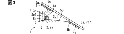
- FIG. 1 is a cross-sectional view showing an example of an in-vehicle device.
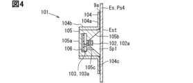
- FIG. 1 is a cross-sectional view showing an example of an in-vehicle device.
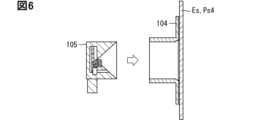
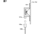
- 5 is a diagram for explaining a method of mounting the in-vehicle device of FIG. 4 on a vehicle.
- 5 is a diagram for explaining a method of mounting the in-vehicle device of FIG. 4 on a vehicle.
- 5 is a diagram for explaining a method of mounting the in-vehicle device of FIG. 4 on a vehicle.
- FIG. 2 is a diagram illustrating communication between an in-vehicle device and an ECU.
- FIG. 1 is a cross-sectional view showing an example of an in-vehicle device.
- FIG. 1 is a cross-sectional view showing an example of an in-vehicle device.
- FIG. 1 is a cross-sectional view showing an example of an in-vehicle device.
- FIG. 1 is a cross-sectional view showing an example of an in-vehicle device.
- 13 is a diagram for explaining a method of mounting the in-vehicle device of FIG. 12 on a vehicle.
- 13 is a diagram for explaining a method of mounting the in-vehicle device of FIG. 12 on a vehicle.
- FIG. 13 is a diagram for explaining a method of mounting the in-vehicle device of FIG. 12 on a vehicle.
- FIG. 1 is a cross-sectional view showing an example of an in-vehicle device.
- 17A and 17B are diagrams illustrating a method of mounting the in-vehicle device of FIG. 16 on a vehicle.
- 17A and 17B are diagrams illustrating a method of mounting the in-vehicle device of FIG. 16 on 17A and 17B are diagrams illustrating a method of mounting the in-vehicle device of FIG. 16 on a vehicle.
- FIG. FIG. FIG. 1 is a cross-sectional view showing an example of an in-vehicle device.
- FIG. 1 is a cross-sectional view showing an example of an in-vehicle device.
- FIG. 1 is a cross-sectional view showing an example of an in-vehicle device.
- FIG. 1 is a cross-sectional view showing an example of an in-vehicle device.
- FIG. 1 is a cross-sectional view showing an example of an in-vehicle device.
- FIG. 1 is a cross-sectional view showing an example of an in-vehicle device.
- FIG. 1 is a cross-sectional view showing an example of an in-vehicle device.
- FIG. 1 is a cross-sectional view showing an example of an in-vehicle device.
- FIG. 1 is a cross-sectional view showing an example of an in-vehicle device.
- the on-vehicle device (General configuration of the in-vehicle device)
- the on-vehicle device according to the present disclosure is configured to be mounted on a vehicle Ve shown in Fig. 1.
- the on-vehicle device has a structure in which an electromagnetic wave element and an acoustic sensor are integrated together.
- the electromagnetic wave element performs at least one of emitting electromagnetic waves toward the outside of the vehicle-mounted device and detecting electromagnetic waves from the outside.
- the electromagnetic waves referred to here may be electromagnetic waves of any wavelength, such as radio waves, microwaves, infrared rays, visible light, and ultraviolet rays.
- Examples of the electromagnetic wave element include cameras, millimeter wave radars, LiDARs, lighting devices, communication devices, rain sensors, and illuminance sensors.
- the camera is a sensor that detects electromagnetic waves from outside the vehicle-mounted device.
- the electromagnetic waves handled by the camera may be visible light or near-infrared light.
- the camera may be a camera for autonomous driving or driving assistance purposes that is installed facing the outside of the vehicle Ve, captures the surrounding environment of the vehicle Ve, and detects dynamic objects such as vehicles and pedestrians, or static objects such as buildings and fallen objects, that exist in the surrounding environment.
- the camera may be used for parking assistance purposes, etc., by working in conjunction with other vehicle-mounted cameras to generate a composite image of the vehicle Ve as seen from above and presenting it to the driver.
- the camera may be a camera for facial recognition of drivers who are about to get into the vehicle.
- Millimeter-wave radar is a sensor that both emits electromagnetic waves toward the outside of the vehicle-mounted device and detects electromagnetic waves from the outside.
- the electromagnetic waves handled by millimeter-wave radar may be millimeter waves.
- Millimeter-wave radar is used for autonomous driving or driving assistance.
- Millimeter-wave radar transmits search waves toward the outside of the vehicle Ve and receives the reflected waves that are reflected back from dynamic or static objects in the surrounding environment.
- LiDAR is a sensor that both emits electromagnetic waves toward the outside of the vehicle-mounted device and detects electromagnetic waves from the outside.
- the electromagnetic waves handled by LiDAR are laser light such as near-infrared light.
- LiDAR is used for autonomous driving or driving assistance.
- LiDAR emits pulsed laser light toward the outside of the vehicle Ve and detects the reflected light that is reflected back by dynamic or static objects in the surrounding environment.
- the time of flight (ToF) of the laser light is used to measure the distance from the LiDAR to the object.
- LiDAR may be configured to detect the three-dimensional shape of an object by scanning the emitted laser light.
- the lighting equipment emits electromagnetic waves toward the outside of the vehicle-mounted device.
- the electromagnetic waves handled by the lighting equipment are visible light.
- the lighting equipment is used to notify the outside of the vehicle.
- the lighting equipment includes passing headlights (low beam), driving headlights (high beam), turn signals, hazard lights, etc.
- the communication device transmits and receives radio waves as electromagnetic waves according to a specified communication standard.
- the rain sensor is a sensor that detects raindrops on the windshield, etc., by emitting light and detecting the reflected or refracted light by the raindrops with a light-receiving element.
- the illuminance sensor is a sensor that detects external light such as sunlight entering the vehicle Ve, and is equipped with a light-receiving element that can measure the illuminance of the external light.
- the acoustic sensor detects sound generated from outside the vehicle-mounted device.
- This source may, for example, match the object that the electromagnetic wave element is detecting, or it may be completely different.
- the detected sound may be sound (i.e., air vibration) coming from outside the vehicle-mounted device, or vibration of the vehicle-mounted device caused by the sound.
- the sound coming from outside the vehicle-mounted device may be a siren emitted by an emergency vehicle such as a police vehicle, fire engine, or ambulance in the external environment of the vehicle Ve.
- the sound coming from outside the vehicle-mounted device may be road noise generated between the vehicle Ve and the road.
- the sound coming from outside the vehicle-mounted device may be engine sound, electric motor sound, etc. inside the vehicle Ve.
- the vehicle-mounted device can be applied to various mounting positions in the vehicle Ve.
- the vehicle-mounted device can be installed inside the front, side, rear and top of the vehicle.
- the external structure has a plate-shaped portion that combines smooth curved and flat surfaces to improve design and aerodynamic characteristics.
- the on-board device is exposed to the outside of the vehicle Ve, and is held in a portion of the external structural part, for example, a plate-like portion, suitable for installation of the electromagnetic wave element.
- the external structural parts on the front side of the vehicle are, for example, the front emblem Pf1, the headlamp cover part Pf2, the front fog lamp cover part Pf3, the bumper corner Pf4, the bumper side Pf5, the front camera cover part Pf6, the windshield Pf7, etc.
- the external structural parts on the sides of the vehicle are, for example, the side mirror mirror surface part Ps1, the side mirror cover part Ps2, the door Ps3, each pillar (B pillar Ps4, etc.), the side fender Ps5, etc.
- the external structural part Es on the rear side of the vehicle is, for example, the backup camera cover part Pb1, the backup sight glass Pb2, the reflector cover part Pb3, the tail lamp module cover part Pb4, the edge of the rear window Pb5, etc.
- This plate-shaped portion (e.g., a cover portion, etc.) of the external structure vibrates when it receives sound coming from the environment external to the vehicle Ve.
- vibrations transmitted from the road surface and vibrations generated when the vehicle Ve collides are transmitted within the external structure, causing the plate-shaped portion to vibrate.
- vibrations caused by the road surface and vibrations generated when the vehicle Ve collides are transmitted and cause the plate-shaped portion to vibrate.
- the acoustic sensor can indirectly detect sound by measuring this vibration and the sound re-emitted by this vibration.
- the camera 2a as the electromagnetic wave element 2 and the acoustic sensor 3 are integrated together.
- the in-vehicle device 1 is attached to the windshield Pf7, which is the external structural part Es, from the inside of the vehicle compartment.
- the windshield Pf7 is formed, for example, in the shape of a translucent curved plate.
- the windshield Pf7 is tilted so that it gradually moves away from the ground on which the vehicle Ve is in contact as it moves from the front to the rear of the vehicle.
- This in-vehicle device 1 includes a bracket 4, a housing 5, a circuit board 6, a camera 2a, an acoustic sensor 3, etc.
- the bracket 4 is a member for attaching the housing 5 to the vehicle Ve.
- the bracket 4 is formed from a metal such as steel (plated or electrocoated) or aluminum.
- the bracket 4 includes an attachment portion 4a, a housing holding portion 4b, and an opening 4c.
- the mounting portion 4a has a plate shape that conforms to the shape of the windshield Pf7.
- the mounting portion 4a is held to the windshield Pf7 via an adhesive 9a that is applied in a layer over substantially the entire surface of the mounting portion 4a on the windshield Pf7 side.
- the housing holding portion 4b is provided on the mounting portion 4a on the side opposite the windshield Pf7, and holds the housing 5 by, for example, engaging or fastening.
- the opening 4c is formed as an opening in the center of the mounting portion 4a. The opening 4c allows light from the external environment of the vehicle Ve to enter the camera 2a through the windshield Pf7.
- the housing 5 is fixed to the windshield Pf7 via the bracket 4.
- the housing 5 is provided in common for the camera 2a and the acoustic sensor 3.
- the housing 5 is formed from a metal such as aluminum.
- the housing 5 includes a board accommodating section 5a, a hood section 5b, and a sound guide hole 5c.
- the board accommodating section 5a is located on the opposite side of the windshield Pf7 to the camera 2a.
- the board accommodating section 5a forms an accommodating space Sp2 that accommodates the board 6.
- the hood portion 5b forms a light-shielding space Sp1 between the camera 2a and the windshield Pf7.
- the light-shielding space Sp1 has a tapered shape according to the angle of view of the camera 2a, expanding in width as it moves away from the camera 2a and approaches the windshield Pf7.
- the hood portion 5b blocks diffusely reflected light from the light incident from the external environment, which leads to a decrease in the quality of the image captured by the camera 2a. In order to absorb the diffusely reflected light, it is preferable that the surface of the hood portion 5b that contacts the space is formed in a dark color.
- the upper and lower hoods of the hood portion 5b have asymmetric shapes that correspond to the inclined shape of the windshield Pf7.
- the taper angle of the upper hood is set to an angle larger than the taper angle of the lower hood.
- the taper angle here is defined as the angle of the surface of the hood portion 5b relative to the optical axis of the camera 2a.
- the sound guide hole 5c is a hole that connects the storage space Sp2 of the substrate 6 and the light-shielding space Sp1 of the hood portion 5b.
- the sound guide hole 5c is, for example, an elongated tubular hole that extends linearly and has a circular cross section.
- the sound guide hole 5c guides the sound in the light-shielding space Sp1 to the storage space Sp2 in which the microphone 3a described below is installed.
- the end of the sound guide hole 5c on the storage space Sp2 side should be formed in a position facing the microphone 3a mounted on the substrate 6.
- the end of the sound guide hole 5c on the light-shielding space Sp1 side should be formed on the camera 2a side of the midpoint between the camera 2a (more specifically, the camera unit) and the windshield Pf7 in the hood portion 5b.
- the board 6 is formed in a flat plate shape from synthetic resin such as glass epoxy resin.
- the board 6 is fixed to the housing 5 by, for example, engagement, fastening, etc.
- the board 6 is a board common to the camera 2a and the acoustic sensor 3.
- the board 6 is mounted with a control circuit for the camera 2a.
- the board 6 also is mounted with the microphone 3a and control circuit for the acoustic sensor 3. Both control circuits are mounted in a form that shares a connector for electrical connection to the vehicle Ve side.
- Camera 2a includes a camera unit and a control circuit.
- the camera unit is constructed integrally by housing an image sensor and a lens system in a lens barrel.
- the camera unit is placed at the tapered end of the light-shielding space Sp1.
- the imaging element is disposed on the opposite side of the lens system from the windshield Pf7.
- the imaging element is, for example, a CCD or CMOS, and is electrically connected to a control circuit mounted on the substrate 6 via a flexible cable. Detection signals acquired by the imaging element are sequentially transmitted to the control circuit.
- the control circuit generates image data.
- the lens system includes one or more lenses. The lens system focuses light incident through the windshield Pf7 and the light-shielding space Sp1, and forms an image on the imaging element.
- the acoustic sensor 3 includes a microphone 3a and a control circuit.
- the microphone 3a is mounted on the substrate 6 in a position facing the sound guide hole 5c.
- the microphone is, for example, a condenser microphone, and in this embodiment, a MEMS microphone 3a is used.
- MEMS is an abbreviation for Micro Electro Mechanical Systems.
- the MEMS microphone 3a is a microphone element that converts air vibrations into an electrical signal.
- the MEMS microphone 3a outputs the change in capacitance that occurs when a thin diaphragm (membrane) vibrates due to sound pressure as an analog electrical signal.
- the MEMS microphone 3a introduces and detects the sound that has reverberated in the light-shielding space Sp1 through the sound guide hole 5c.
- the shape of the hood portion 5b which is for blocking diffusely reflected light, i.e., its horn-like structure, is used to increase the sound pressure and then detect the sound.
- the analog electrical signal from the MEMS microphone 3a is converted to a digital sound signal by a control circuit.
- the in-vehicle device 101 in the example of FIG. 4 differs from the example of FIG. 3 in that it is attached to a B-pillar Ps4 as an external structural part Es.
- the cover part exposed to the external environment in the B-pillar Ps4 is formed in a plate shape having a light-transmitting plate part Est that transmits light so that light can be incident on the camera 2a through the light-shielding space Sp1.
- the light-transmitting plate part Est extends approximately perpendicular to the ground.
- the parts of the B-pillar Ps4 other than the light-transmitting plate part Est may be formed in a dark color that has no transparency.
- the bracket 104 has the mounting portion 104a and the opening 104c similar to those in FIG. 3, and also has a housing housing portion 104b.
- the housing housing portion 104b is formed in a cylindrical shape so as to extend from the opening 104c toward the opposite side of the light-transmitting plate portion Est.
- the housing housing portion 104b is housed in the housing 105.
- the housing housing portion 104b may have a cutout portion for passing the connector 107a when housed in the housing 105.
- the hood portion 105b has an upper hood and a lower hood that are approximately symmetrical in shape.
- the taper angle of the upper hood is set to be approximately equal to the taper angle of the lower hood.
- the hood portion 105b has a sound guide hole 105c that communicates between the MEMS microphone 103a of the acoustic sensor 103 mounted on the substrate 106 and the light-shielding space Sp1, as in the example of FIG. 3.
- FIG. 5 This mounting process can be said to represent part of the manufacturing method for the vehicle-mounted device 101 or the vehicle Ve.
- adhesive 9a is applied to the mounting portion 104a of the bracket 104, and the bracket 104 is pressed against the light-transmitting plate portion Est of the B-pillar Ps4.
- the bracket 104 is fixed to the light-transmitting plate portion Est.
- the housing 105 with the camera 102a and acoustic sensor 103 assembled thereto is inserted into the housing accommodating portion 104b of the bracket 104. This fixes the camera 102a and acoustic sensor 103 to the light-transmitting plate portion Est and the bracket 104.
- the connector 108a on the harness 108b side is connected to the connector 107a on the housing 105 side. This electrically connects the two control circuits 102b, 103b to the ECU (electronic control unit) 0 on the vehicle Ve side with the harness 108b shared by the camera 102a and acoustic sensor 103. This completes the installation of the in-vehicle device 101 to the vehicle Ve.
- the detection signal acquired by the image sensor of the camera 102a in the in-vehicle device 101 is subjected to image processing and data format conversion by the control circuit 102b of the camera 102a, and image data is generated.
- the analog electrical signal acquired by the microphone 103a of the acoustic sensor 103 in the in-vehicle device 101 is amplified by the amplifier in the control circuit 103b, and then converted into a digital signal by the AD conversion circuit. This digital signal is further subjected to signal processing and data format conversion, and a sound signal is generated.
- the image data and sound signals are sent to ECU0 from the same bus interface (bus IF) through a shared harness 108b.
- the harness 108b includes three types of lines: a power line, a GND line, and a communication line.
- the wiring shared by the image data and sound signals may be at least one of these three types of wiring, and it is more preferable that all three types of wiring are shared.
- the communication between the in-vehicle device 101 and the ECU0 is, for example, high-speed serial communication such as LVDS (Low Voltage Differential Signaling) communication or A2B (Automotive Audio Bus; A2B is a registered trademark). Digitalized sound signals are transferred to the ECU0 side through such communication.
- LVDS Low Voltage Differential Signaling
- A2B Automatic Audio Bus
- the ECU 0 is a processing device that executes necessary processing in the vehicle Ve.
- the ECU 0 includes a power supply 0a, a video input/output terminal, and a microcomputer 0b.
- the power supply 0a supplies power to the camera 102a and acoustic sensor 103 of the in-vehicle device 101 through the power line of the harness 108b.
- the microcomputer 0b acquires image data and sound signals transmitted from the in-vehicle device 101 via the video input/output terminal.
- the microcomputer 0b may use the image data and sound signals for the same purpose, or may use them for separate purposes.
- the electromagnetic wave element 2, 102 and the acoustic sensor 3, 103 are integrated in the in-vehicle device 1, 101.
- the in-vehicle device 1, 101 includes a housing 5, 105 that houses the electromagnetic wave element 2, 102.
- the acoustic sensor 3, 103 is housed in the same housing 5, 105 and has a microphone 3a, 103a that detects air vibrations as sound.
- the microphone 3a, 103a uses the air present in the internal space of the housing 5, 105 that houses the electromagnetic wave element 2, 102, making it possible to detect sound in a small space.
- the electromagnetic wave element 2, 102 is a camera 2a, 102a that captures the outside of the device.
- the housing 5, 105 has a shape according to the angle of view of the camera 2a, 102a that gradually expands the width of the internal space as it moves away from the camera 2a, 102a, and is provided with a hood portion 5b, 105b that blocks diffusely reflected light entering from the outside of the device.
- the housing 5, 105 also has a board housing portion 5a, 105a that is a board shared between the camera 2a, 102a and the acoustic sensor 3, 103, and houses a board 6, 106 on which the microphone 3a, 103a is mounted.
- the hood portion 5b, 105b has a sound guide hole 5c, 105c that communicates between the microphone 3a, 103a and the internal space.
- sound detection performance can be improved because sound can be detected at increased sound pressure by using a hood structure similar to the horn structure of cameras 2a and 102a.
- the harness that electrically connects the electromagnetic wave element 102 to the ECU 0, which is another device of the vehicle Ve, and the harness that electrically connects the acoustic sensor 103 to the ECU 0 are shared.
- the harness 108b By sharing the harness 108b, the increase in the number of installation steps can be further suppressed.
- the acoustic sensor 103 generates a sound signal by converting the detected analog electric signal into a digital signal.
- the communication line through which the electromagnetic wave element 102 communicates with the ECU 0, which is another device of the vehicle Ve, and the communication line through which the acoustic sensor 103 communicates with another device are shared in a form of communicating digital signals.
- Second Embodiment 9 and 10 the second embodiment is a modification of the first embodiment.
- the second embodiment will be described focusing on the differences from the first embodiment.
- the in-vehicle device 11 is attached to the windshield Pf7 as the external structure Es, similarly to the example of FIG. 3.
- the example of FIG. 9 will be described focusing on the differences from the example of FIG. 3.
- the microphone of the acoustic sensor 13 is a piezoelectric microphone 13a.
- the piezoelectric microphone 13a is configured to include a piezoelectric element and a metal plate.
- the piezoelectric element is formed in a thin plate shape.
- a positive electrode is formed on the front side of the piezoelectric element, and a negative electrode is formed on the back side.
- the piezoelectric element generates a voltage between the electrodes according to the input stress.
- the metal plate is formed in a thin plate shape with an area larger than that of the piezoelectric element.
- the metal plate vibrates integrally with the piezoelectric element due to the vibration transmitted to the piezoelectric microphone 13a.
- the piezoelectric microphone 13a may be configured to include a piezoelectric element having a plate thickness.
- the piezoelectric microphone 13a is therefore positioned at a location where it is directly affected by vibrations from the windshield Pf7.
- the opening 14c of the bracket 14 has space for the piezoelectric microphone 13a to face the windshield Pf7.
- the housing 15 has a recess 15d for placing the piezoelectric microphone 13a in a position on its outer wall that faces the windshield Pf7 above the hood portion.
- the piezoelectric microphone 13a is sandwiched between elastic bodies 13c and 13d at its front and back, with approximately half of its volume buried in, for example, a cylindrical recess 14d.
- the elastic body 13c on the front side is preferably a viscoelastic body that has both viscosity and elasticity.
- the viscoelastic body is a double-sided tape or adhesive that functions as an acoustic matching material.
- the piezo microphone 13a is positioned in a state where it is pressed against the windshield Pf7 via the viscoelastic body.
- the elastic body 13d on the rear side is, for example, a resin spring, a metal spring, rubber, etc. This makes it possible to efficiently transmit vibrations from the windshield Pf7 to the piezo microphone 13a while absorbing differences in the shape of the windshield Pf7 and installation position errors depending on the vehicle model.
- the in-vehicle device 111 is attached to the light-transmitting plate portion Est of the B-pillar Ps4 serving as the external structure Es.
- the microphone of the acoustic sensor 113 is a piezoelectric microphone 113a.
- the housing 115 housed in the housing housing portion 114b of the bracket 114 has a recess 115d adjacent to the hood portion and facing the light-transmitting plate portion Est, in which the entire piezoelectric microphone 113a is embedded.
- the rear side of the piezoelectric microphone 113a is provided with an elastic body 111d, as in the example of FIG. 9.
- the front side of the piezoelectric microphone 113a has an adhesive 9a for attaching the bracket 114 formed between the light-transmitting plate portion Est, so that the adhesive 9a has the same function as the viscoelastic body in the example of FIG. 9.
- the in-vehicle device 11, 101 is fixed to the external structure Es of the vehicle Ve and includes a housing 15, 115 that houses the electromagnetic wave element 12, 112.
- the acoustic sensor 13, 113 is held on the outer wall of the housing 15, 115 so as to share the housing 15, 115 with the electromagnetic wave element 12, 112, and is positioned at a position where vibrations of the external structure Es are transmitted, and has a microphone 13a, 113a that detects vibrations of the external structure Es.
- the microphones 13a, 113a are in close contact with the external structure Es with the elastic bodies 13c, 113c as viscoelastic bodies disposed between the microphones 13a, 113a and the external structure Es.
- This configuration makes it possible to easily increase the vibration transmission between the microphones 13a, 113a and the external structure Es while suppressing an increase in the number of installation steps.
- the microphone 13a, 113a is in close contact with the external structure Es with the elastic body 13d, 113d disposed between the microphone 13a, 113a and the housing 15, 115.
- the elastic body 13d, 113d absorbs dimensional errors during installation, making installation easy.
- the third embodiment is a modification of the first embodiment.
- the third embodiment will be described focusing on the differences from the first embodiment.
- the in-vehicle device 21 is attached to the windshield Pf7 as the external structural part Es.
- the example of FIG. 11 will be described focusing on the differences from the example of FIG. 3.
- the housing 25 is formed by integrating a first housing part 25X and a second housing part 25Y.
- the first housing part 25X is a housing part that houses the camera 22a as the electromagnetic wave element 22.
- the first housing part 25X includes a board accommodating part 25a and a hood part 25b.
- the board 26 housed in the board accommodating part 25a is provided exclusively for mounting the control circuit of the camera 22a.
- the second housing part 25Y is a housing part that houses the acoustic sensor 23.
- the second housing part 25Y is fixed to the first housing part 25X by, for example, attaching with an adhesive, engaging, fastening, or other methods.
- the second housing part 25Y has a recess 25d at a position facing the windshield Pf7.
- the recess 25d houses the microphone 23a of the acoustic sensor 23.
- the microphone may be a condenser microphone or a piezoelectric microphone, but since it is difficult to provide space in the recess 25d for generating air vibrations that the condenser microphone detects, it is more preferable in that respect to use a piezoelectric microphone.
- the in-vehicle device 121 is attached to the translucent plate portion Est of the B-pillar Ps4 as the external structure Es, as in the example of FIG. 4.
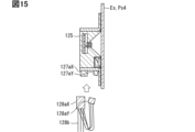
- the housing 125 housed in the housing housing portion 124b of the bracket 124 is formed by integrating the first housing part 125X and the second housing part 125Y.
- the first housing part 125X is a housing part that houses the camera 122a as the electromagnetic wave element 122.
- the first housing part 125X includes a board housing portion 125a and a hood portion 125b.
- the board 126 housed in the board housing portion 125a is provided exclusively for mounting the control circuit of the camera 122a.
- the first housing part 125X forms a space for placing the second housing part 125Y at the corner portion 125e adjacent to the hood portion 125b and facing the translucent plate portion Est.
- the second housing part 125Y is a housing part that houses the acoustic sensor 123.
- the second housing part 125Y is fixed to the first housing part 125X by, for example, attaching with an adhesive, engaging, fastening, or other methods.
- the integrated first housing part 125X and second housing part 125Y form a cylindrical housing 125 with almost no gap in the housing housing part 124b.
- the connectors on the housing 125 side are provided separately for the connector 127aX of the first housing part 125X and the connector 127aY of the second housing part 125Y.
- the connector on the harness 128b side branches the wiring from the connector 128aX corresponding to the first housing part 125X to the connector 128aY corresponding to the second housing part 125Y, so that the camera 122a and the acoustic sensor 123 share the harness 128b and both control circuits are electrically connected to the ECU0 on the vehicle Ve side.
- the camera 122a and acoustic sensor 123 are assembled in the housing accommodating portion 124b of the bracket 124, and the housing 125 consisting of the first housing part 125X and the second housing part 125Y that have been previously integrated is inserted. This fixes the camera 122a and the acoustic sensor 123 to the light-transmitting plate part Est and the bracket 124.
- the two connectors 128aX, 128aY on the harness 128b side are respectively connected to the two connectors 127aX, 127aY on the housing 125 side. This completes the installation of the in-vehicle device 121 to the vehicle Ve.
- the in-vehicle device 21, 121 includes a first housing part 25X, 125X that houses the electromagnetic wave element 22, 122, and a second housing part 25Y, 125Y that houses the acoustic sensor 23, 123.
- the second housing part 25Y, 125Y is fixed to the first housing part 25X, 125X, so that the acoustic sensor 23, 123 is integrated with the electromagnetic wave element 22, 122.
- the fourth embodiment is a modification of the first embodiment.
- the fourth embodiment will be described focusing on the differences from the first embodiment.
- the in-vehicle device 131 is attached to the light-transmitting plate portion Est of the B-pillar Ps4, which serves as the external structural portion Es.
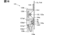
- the example of Figure 16 will be described focusing on the differences from the example of Figure 4.
- a first housing part 135X and a second housing part 135b are provided separately.
- the first housing part 135X is a housing part that is accommodated in the housing accommodating portion 134b of the bracket 134, and is a housing part that accommodates the camera 132a, which serves as the electromagnetic wave element 132.
- the second housing part 135Y is a housing part that houses the acoustic sensor 133.
- the second housing part 135Y is fixed to the plate-shaped mounting part 124a of the bracket 124. Specifically, the second housing part 135Y is attached to the back surface of the mounting part 134a with adhesive 9a from the side opposite the light-transmitting plate part Est across the mounting part 134a.
- the second housing part 135Y has a recess at a position facing the light-transmitting plate part Est across the mounting part 124a.
- the recess houses the microphone 133a of the acoustic sensor 133.
- the microphone 133a may be a condenser microphone or a piezoelectric microphone, but since it is difficult to provide space in the recess for generating air vibrations that a condenser microphone detects, it is more preferable to use a piezoelectric microphone that directly detects vibrations of the B-pillar Ps4 and the mounting part 134a.
- the connectors on the in-vehicle device 131 side are provided separately as connector 137aX of the first housing part 135X and connector 137aY of the second housing part 135Y.
- the connectors 138aX and 138Y on the harness 138b side are the same as in the example of FIG. 12.
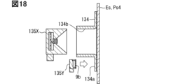
- adhesive 9a is applied to the mounting portion 134a of the bracket 134, which is then pressed against the translucent plate portion Est of the B-pillar Ps4. When the adhesive 9a dries, the bracket 134 is fixed to the translucent plate portion Est.
- the first housing part 135X with the camera 132a attached thereto is inserted into the housing accommodating portion 134b of the bracket 134. This fixes the camera 132a to the light-transmitting plate portion Est and the bracket 134.
- adhesive 9a is applied to the surface of the piezo microphone 133a that contacts the back surface of the mounting portion 134a of the bracket 134. Then, the second housing part 135Y is pressed against the back surface. When the adhesive 9a dries, the acoustic sensor 133 is fixed to the light-transmitting plate portion Est and the bracket 134.
- the two connectors 138aX and 138aY on the harness 138b side are connected to the two connectors 137aX and 137aY on the in-vehicle device 131 side, respectively. This completes the installation of the in-vehicle device 131 to the vehicle Ve.
- the in-vehicle device 131 includes a bracket 134 that is attached to the external structure Es of the vehicle Ve.
- the in-vehicle device 131 also includes a first housing part 135X that houses the electromagnetic wave element 132, and a second housing part 135Y that houses the acoustic sensor 133.
- the first housing part 135X is fixed to the bracket 134
- the second housing part 135Y is fixed to the bracket 134, thereby integrating the acoustic sensor 133 with the electromagnetic wave element 132.
- This integration makes it possible to suppress an increase in the number of steps required to attach the in-vehicle device 21, 121 to the vehicle Ve.
- the fifth embodiment is a modification of the fourth embodiment.
- the fifth embodiment will be described focusing on the differences from the fourth embodiment.
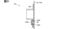
- the second housing part 145Y, 155Y is attached to the back surface of the mounting part 144a of the bracket 144, 154 using a pressure spring structure 144d, 154d instead of adhesive. Note that the first housing part and the camera are not shown in Figures 20 and 21.
- the pressure spring structure 144d is provided on the rear side of the mounting portion 144a.
- the pressure spring structure 144d is formed of, for example, metal, and has a rotating shaft portion 144e, an engaging portion 144g, and a pressing portion 144f.
- the rotating shaft portion 144e is fixed to a position of the mounting portion 144a that is offset from the position facing the second housing part 125Y.
- the rotating shaft portion 144e is connected to the pressing portion 144f so that the pressing portion 144f can rotate in a space on the rear side of the mounting portion 144a with the rotating shaft portion 144e as the center of rotation.
- the rotating shaft portion 144e exerts an elastic reaction force of the pressing portion 144f toward the mounting portion 144a side by using, for example, a coil spring.
- the engaging portion 144g is fixed to the mounting portion 144a on the opposite side of the second housing part 145Y from the rotating shaft portion 144e.
- the engaging portion 144g is formed so as to be able to engage with the tip of the pressing portion 144f.
- the pressing portion 144f is formed in a plate or rod shape that extends to a length that can reach the engaging portion 144g.
- the pressing portion 144f is configured so that, due to the above-mentioned rotation, it is able to engage with the engaging portion 144g when the second housing part 145Y is assembled from a state in which it is separated from the engaging portion 144g before the second housing part 145Y is assembled to the mounting portion 144a.
- the pressing portion 144f presses the second housing part 145Y toward the light-transmitting plate part Est or the mounting part 144a.
- This allows the piezoelectric microphone 143a to be in close contact with the light-transmitting plate part Est and the mounting part 144a without using adhesive 9a, and to directly detect vibrations from these.
- the degree of contact can be increased by applying adhesive 9a to the surface of the piezoelectric microphone 143a that comes into contact with the back surface of the mounting part 144a of the second housing part 145Y as shown in FIG. 20.
- the pressing portion 144f may directly press the main body portion of the second housing part 145Y that houses the microphone 143a.
- a flange may be provided in the second housing part 145Y that protrudes from the main body portion in a direction substantially parallel to the extension direction of the mounting portion, and the pressing portion 144f may press the flange.
- the bracket 154 of the in-vehicle device 151 has an opening 154h formed in a position facing the second housing part 155Y.
- the second housing part 155Y is pressed directly against the light-transmitting plate part Est through the opening 154h by the pressing spring structure 154d similar to that of FIG. 20.
- the in-vehicle device 141, 151 is provided with a pressing spring structure 144d, 154d that elastically presses the second housing part 145Y, 155Y toward the external structure part Es. Since vibrations of the external structure part Es are easily transmitted to the second housing part 145Y, 155Y, the sound detection performance can be improved.
- the bracket 154 also has an opening 154h that opens in a position facing the external structure Es.
- the in-vehicle device 151 further includes a pressing spring structure 154d that uses the opening 154h to directly press the second housing part 155Y against the external structure Es by its elasticity. This makes it easier for vibrations of the external structure Es to be transmitted to the second housing part 155Y, thereby improving sound detection performance.
- the sixth embodiment is a modification of the first embodiment.
- the sixth embodiment will be described focusing on the differences from the first embodiment.
- the in-vehicle device 201 is attached to the body, bumper, grill, etc., as the external structure Es.
- the external structure Es is provided with an opening Eso for exposing the in-vehicle device 201 to the outside.
- the housing 205 accommodated in the housing accommodation portion 204b of the bracket 204 includes a lens barrel portion 205f and a board holding portion 205g.
- the lens barrel portion 205f is formed in a cylindrical shape to accommodate the lens system 202c of the camera 202a as the electromagnetic wave element 202.
- the lens system 202c includes multiple lenses 202d, 202e, and 202f.
- the frontmost exposed lens 202d is disposed in the opening Eso and is exposed to the external environment of the vehicle Ve.
- the board holding section 205g is disposed on the rear side of the lens barrel section 205f, i.e., on the opposite side of the exposed lens 202d with other lenses in between.
- the board holding section 205g covers the rear side of the housing 205 and forms a holding space inside that holds the board 206.
- the board 206 is held facing the lens system 202c on the optical axis Ao of the lens system 202c.
- the image sensor 202g is mounted on the board 206 on the optical axis Ao of the lens system 202c.
- the microphone of the acoustic sensor 203 is a condenser microphone, a MEMS microphone 203a.
- the MEMS microphone 203a shares the substrate 206 with the image sensor 202g.
- the MEMS microphone 203a is arranged on the substrate 206 outside the optical axis Ao that is offset from the image sensor 202g, facing the lens system 202c.
- the MEMS microphone 203a detects air vibrations in the space formed to place the lens system 202c. In other words, the MEMS microphone 203c measures the sound that is re-radiated by sounds generated in the external environment that vibrate the lenses 202d, 202e, and 202f of the lens system 202c.
- the lens barrel portion 215f has a sound guide hole 215h that connects between the front end and rear end of the lens barrel portion 215f along the direction of the optical axis Ao.
- the sound guide hole 215h is an elongated tubular hole with a circular cross section that extends in a straight line.
- the front end of the sound guide hole 215h that is exposed to the external environment is blocked by a sound-permeable filter 215i that is both sound-permeable and waterproof.
- the sound filter 215i is formed, for example, in the shape of a film or thin plate.
- the rear end of the sound guide hole 215h faces the MEMS microphone 213a mounted on the substrate 216.
- the lens barrel portion 225f also has a sound guide hole 225h.
- the sound guide hole 225h connects the rear end of the lens barrel portion 225f to the space formed between the multiple lenses 222d, 222e, and 222f in the lens system 222c.
- the sound guide hole 225h has a bent portion 225j and connects from the rear end to a position on the inner wall of the lens barrel portion 225f that is formed between the exposed lens 222d and the second lens 222e that faces the exposed lens 222d. In this case, the sound guide hole 225h is not directly exposed to the external environment, so a sound filter is not required.
- the in-vehicle devices 211, 221 are provided with housings 215, 235 that house the electromagnetic wave element 202.
- the acoustic sensor 203 is housed in the housing 215 and has a microphone 213a that detects air vibrations as sound.
- the housing 215 has a sound guide hole 215h that connects the microphone 213a to the outside of the device. The sound guide hole 215h guides sound from outside the device directly to the microphone 213a, improving detection performance.
- the sound guide hole 215h connects the microphone 213a to the surrounding environment of the vehicle Ve, which is outside the device.
- the housing 215 further includes a sound-permeable filter 215i that is arranged to cover the sound guide hole 215h and is both sound-permeable and waterproof. This can prevent foreign matter from entering the housing 215 from the external environment through the sound guide hole 215h. This makes it possible to provide an in-vehicle device 211 that can maintain its detection performance for a long period of time.
- the in-vehicle device 221 includes a housing 225 that houses the electromagnetic wave element 202.
- the acoustic sensor 223 is housed in the housing 225 and has a microphone 223a that detects air vibrations as sound.
- the electromagnetic wave element 202 has a lens system 222c that has a plurality of lenses including an exposed lens 222d exposed to the surrounding environment of the vehicle Ve and other lenses 222e and 222f.
- the housing 225 has a sound guide hole 225h that communicates between the microphone 223a and the space formed between the exposed lens 222d and the other lenses 222e and 222f in the lens system 222c.
- the exposed lens 222d performs both a function for the electromagnetic wave element 202 and a sound filter function for the sound guide hole 225h. This prevents foreign matter from entering the housing 225 from the external environment through the sound guide hole 225h, allowing detection performance to be maintained for a long period of time.
- the seventh embodiment is a modified example of the sixth embodiment.
- the seventh embodiment will be described focusing on the differences from the sixth embodiment.
- the seventh embodiment employs a configuration that enhances sound collection performance not only for the outside of the vehicle but also for the interior space of the vehicle Ve.
- a MEMS microphone 233a is mounted on the rear side of the board 236, opposite the front side on which the imaging element 232g is mounted.
- a sound guide hole 235h is formed in the bottom surface of the board holding portion 235g that covers the rear side of the housing 235.
- the sound guide hole 235h connects the position inside the housing 235 facing the MEMS microphone 233a to the outside of the device.
- the acoustic sensor 233 can easily detect sound in the internal space of the vehicle Ve on the side opposite the external structure portion Es.
- a sound-transmitting filter 235i may be provided at the end of the sound guide hole 235h that is exposed to the internal space of the vehicle Ve.
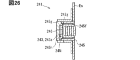
- a sound guide hole 245h is formed in a wall portion of the substrate holding portion 245g that protrudes cylindrically from the bottom toward the lens barrel portion 245f.
- a MEMS microphone 243a is mounted on the rear side of the substrate 246, opposite the front side on which the imaging element 242g is mounted, at a position close to the wall portion that is eccentric from the center (on the optical axis) of the substrate 246.
- the sound guide hole 245h connects the vicinity of the inner MEMS microphone 243a to the outside.
- the acoustic sensor 243 can easily detect sounds in the internal space of the vehicle Ve.
- a sound filter 245i may be provided at the end of the sound guide hole 245h that is exposed to the internal space of the vehicle Ve.
- the eighth embodiment is a modification of the sixth and seventh embodiments.
- the eighth embodiment will be described focusing on the differences from the sixth and seventh embodiments.
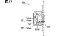
- both a MEMS microphone 253aX and a sound guide hole 255hX corresponding to the arrangement in the example of FIG. 24, and a MEMS microphone 253aY and a sound guide hole 255hY corresponding to the arrangement in FIG. 25 are provided.
- the acoustic sensor 253 uses a control circuit implemented on the substrate 256 to synthesize the sound signals detected by the two MEMS microphones 253aX and 253aY after conversion into analog electrical signals or digital signals.
- the synthesis process here may be capable of performing a process for improving detection performance by active noise canceling.
- the in-vehicle device 251 includes a housing 255 that houses an electromagnetic wave element.
- the acoustic sensor 253 includes a first microphone 253aX that is housed in the housing 255 and detects air vibrations as sound, and a second microphone 253aY that is separate from the first microphone 253aX and is housed in the housing 255 and detects air vibrations as sound.
- the housing 255 includes a first sound guide hole 255hX that guides sounds from the external environment of the vehicle Ve to the first microphone 253aX, and a second sound guide hole 255hY that guides sounds from the internal space of the vehicle Ve to the second microphone 253aY. Therefore, sounds from both the external environment and the internal space of the vehicle Ve can be detected, and it can be used to improve the performance of, for example, noise canceling.
- the ninth embodiment is a modification of the sixth embodiment.
- the ninth embodiment will be described focusing on the differences from the sixth embodiment.
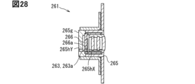
- a configuration is adopted for the MEMS microphone 263a corresponding to the example of FIG. 24 that improves the sound collection performance into the interior of the vehicle Ve.
- a sound guide hole 266a is provided directly below the mounting position of the MEMS microphone 263a in the substrate 266.
- a sound guide hole 265hY is provided at the end of a linear extension of the sound guide hole 266a at the bottom of the substrate holding portion 265g.
- one MEMS microphone 263a detects both sounds that are directional in the external environment of the vehicle Ve and sounds that are directional inside the vehicle.
- the acoustic sensor 263 can perform processing to improve detection performance through passive noise cancellation using a control circuit implemented on the substrate 266.
- the in-vehicle device 261 includes a housing 265 that houses an electromagnetic wave element.
- the acoustic sensor 263 is housed in the housing 265 and has a microphone 263a that detects air vibrations as sound.
- the housing 265 has a first sound guide hole 265hX that guides sounds from the external environment of the vehicle Ve to the microphone 263a, and a second sound guide hole 265hY that guides sounds from the internal space of the vehicle Ve to the microphone 263a. Therefore, it is possible to detect sounds from both the external environment and the internal space of the vehicle Ve, and it is possible to use this to improve the performance of, for example, noise canceling.
- the LiDAR or lighting device as the electromagnetic wave element 302 and the acoustic sensor 303 are integrated.
- This in-vehicle device 301 is attached to the body, bumper, grill, etc. as the external structure Es.
- the external structure Es is provided with an opening Eso for exposing the in-vehicle device 301 to the outside.
- the bracket 304 is the same as the example in FIG. 22.
- the housing 305 is housed in the cylindrical portion of the bracket 304.
- the housing 305 includes a cup-shaped substrate holding portion 305k with a bottom on the rear side, and a translucent cover portion 305m made of, for example, glass or acrylic resin, which covers the substrate holding portion 305k from the front side.
- the board 306 is arranged in a form held by the board holding part 305k.
- the electromagnetic wave device 302g and the MEMS microphone 303a of the acoustic sensor 303 are mounted on the front side of the board 306 facing the light-transmitting cover part 305m.
- the electromagnetic wave device 302g is a light-emitting element that emits laser light and a light-receiving element that receives laser light.
- the electromagnetic wave device 302g is a light-emitting element such as an LED.
- a millimeter wave radar as the electromagnetic wave element 402 and an acoustic sensor 403 are integrated.
- This on-vehicle device 401 is attached to the body, bumper, grill, etc. as the external structure Es.
- the difference from FIG. 29 is that the light handled by the millimeter wave radar is not visible light but millimeter waves, so the translucent cover portion of the housing 405 may be replaced with a cover portion 405n formed, for example, from a colored synthetic resin.
- the electromagnetic wave device 402g may be an antenna array that transmits and receives millimeter waves.
- control unit and the method described in the present disclosure may be realized by a dedicated computer comprising a processor programmed to execute one or more functions embodied in a computer program.
- the device and the method described in the present disclosure may be realized by a dedicated hardware logic circuit.
- the device and the method described in the present disclosure may be realized by one or more dedicated computers configured by a combination of a processor that executes a computer program and one or more hardware logic circuits.
- the computer program may be stored on a computer-readable non-transient tangible recording medium as instructions executed by the computer.
- An in-vehicle device configured to be mounted on a vehicle (Ve), an electromagnetic wave element (2, 22, 102, 122, 132, 202, 222, 302, 402) that performs at least one of emitting an electromagnetic wave toward the outside of the device and detecting an electromagnetic wave from the outside of the device;
- An in-vehicle device comprising: an acoustic sensor (3, 13, 23, 103, 113, 123, 133, 203, 233, 243, 253, 263, 303, 403) integrated with the electromagnetic wave element and detecting sound generated from an external source of the device.
- a housing (5, 105, 205, 215, 225, 235, 245, 305, 405) that houses the electromagnetic wave element
- the acoustic sensor is housed in the housing and has a microphone (3a, 103a, 203a, 213a, 223a, 233a, 243a, 253aX, 253aY, 263a, 303a) that detects vibrations of the air as the sound by utilizing the air present in the internal space of the housing.
- the electromagnetic wave element is a camera (2a, 102a) that captures the outside of the device
- the housing includes: a hood portion (5b, 105b) having a shape corresponding to the angle of view of the camera, which gradually increases the width of the internal space as it moves away from the camera, and which blocks diffusely reflected light entering from outside the device; a substrate accommodating portion (5a, 105a) for accommodating a substrate (6, 106) on which the microphone (3a, 103a) is mounted, the substrate being shared between the camera and the acoustic sensor;
- the in-vehicle device according to Technical Concept 2, wherein the hood portion has a sound guide hole (5c, 105c) that communicates between the microphone and the internal space.
- a housing (15, 115) fixed to an external structure (Es) of the vehicle and housing the electromagnetic wave element;
- the acoustic sensor (13, 113) is held on the outer wall of the housing so as to share the housing with the electromagnetic wave element, and is positioned at a position where vibrations of the external structural part are transmitted, and has a microphone (13a, 113a) that detects vibrations of the external structural part.
- a bracket (134, 144, 154) attached to an external structural portion (Es) of the vehicle;
- the bracket (154) has an opening (154h) that opens at a position facing the external structural portion
- the in-vehicle device according to Technical Concept 8 further includes a pressing spring structure (154d) that uses the opening to directly press the second housing part (155Y) against the external structure by its elasticity.
- a housing (215, 235, 245, 255, 265) for accommodating the electromagnetic wave element
- the acoustic sensor has a microphone (213a, 233a, 243a, 253aY, 266a) that is housed in the housing and detects air vibrations as the sound
- the in-vehicle device according to Technical Idea 1, wherein the housing has sound guide holes (215h, 235h, 245h, 255hY, 265hY, 266a) that communicate between the microphone and the outside of the device.
- the sound guide hole (215h) communicates between the microphone and the surrounding environment of the vehicle as the outside of the device,
- a housing (225) for housing the electromagnetic wave element The acoustic sensor has a microphone (223a) that is housed in the housing and detects vibrations of air as the sound
- the electromagnetic wave element includes a lens system (222c) having a plurality of lenses including an exposed lens (222d) exposed to the surrounding environment of the vehicle and other lenses (222e, 222f);
- a housing for housing the electromagnetic wave element,
- the acoustic sensor (253) A first microphone (253aX) that is housed in the housing and detects vibrations of air as the sound; a second microphone (253aY) that is separate from the first microphone, is housed in the housing, and detects vibrations of air as the sound;
- the housing includes: A first sound guide hole (255hX) for guiding sound from the external environment of the vehicle to the first microphone;
- the in-vehicle device described in Technical Idea 1 has a second sound guide hole (255hY) that guides sound from the interior space of the vehicle to the second microphone.
- a housing for housing the electromagnetic wave element;
- the acoustic sensor (263) is housed in the housing and has a microphone (263a) that detects vibrations of air as the sound,
- the housing includes: A first sound guide hole (265hX) for guiding sound from the external environment of the vehicle to the microphone;
- the in-vehicle device described in Technical Idea 1 has a second sound guide hole (265hY) that guides sound from the interior space of the vehicle to the microphone.
- the acoustic sensor generates a sound signal by converting a detected analog electrical signal into a digital signal;
Landscapes
- Engineering & Computer Science (AREA)
- Radar, Positioning & Navigation (AREA)
- Remote Sensing (AREA)
- Physics & Mathematics (AREA)
- Computer Networks & Wireless Communication (AREA)
- General Physics & Mathematics (AREA)
- Electromagnetism (AREA)
- Acoustics & Sound (AREA)
- Fittings On The Vehicle Exterior For Carrying Loads, And Devices For Holding Or Mounting Articles (AREA)
- Radar Systems Or Details Thereof (AREA)
- Measurement Of Velocity Or Position Using Acoustic Or Ultrasonic Waves (AREA)
- Optical Radar Systems And Details Thereof (AREA)
Abstract
車載装置(1)は、車両(Ve)に搭載されるように構成される。車載装置(1)は、装置外部へ向けた電磁波の放射及び装置外部からの電磁波の検出のうち少なくとも一方を実行する電磁波エレメント(2)と、電磁波エレメント(2)に対して一体化され、装置外部を発生原因とした音響を検出する音響センサ(3)と、を備える。
Description
この出願は、2023年6月12日に日本に出願された特許出願第2023-96458号を基礎としており、基礎の出願の内容を、全体的に、参照により援用している。
この明細書による開示は、車両において音響を検出する技術に関する。
特許文献1には、車両環境をセンシングする環境センサを備える車両のルーフモジュールが開示されている。環境センサは、例えばカメラ、レーダ、LiDAR(Light Detection and Ranging/Laser Imaging Detection and Ranging)、等の光学センサが例示されている。
さて、本開示の発明者らは、光学センサ等に代表される電磁波エレメントの他に、新たに音響を検出する音響センサを車両に搭載することを着想した。しかしながら、車両には他にも多くのエレメントが搭載されるため、音響センサの設置スペースを確保することや音響センサの車両への取付工数増大を抑制することが課題となっている。
この明細書の開示による目的のひとつは、車両への搭載に適した車載装置を提供することにある。
ここに開示された態様のひとつは、車両に搭載されるように構成された車載装置であって、
装置外部へ向けた電磁波の放射及び装置外部からの電磁波の検出のうち少なくとも一方を実行する電磁波エレメントと、
電磁波エレメントに対して一体化され、装置外部を発生原因とした音響を検出する音響センサと、を備える。
装置外部へ向けた電磁波の放射及び装置外部からの電磁波の検出のうち少なくとも一方を実行する電磁波エレメントと、
電磁波エレメントに対して一体化され、装置外部を発生原因とした音響を検出する音響センサと、を備える。
このような車載装置によると、電磁波エレメントと音響センサとが一体化されている。このため、車両における音響センサの設置スペースの確保がより容易なものとなり、また音響センサの車両への取付工数増大を抑制することが可能となる。故に、車両への搭載に適した車載装置を提供することができる。
なお、請求の範囲等に含まれる括弧内の符号は、後述する実施形態の部分との対応関係を例示的に示すものであって、技術的範囲を限定することを意図するものではない。
以下、複数の実施形態を図面に基づいて説明する。なお、各実施形態において対応する構成要素には同一の符号を付すことにより、重複する説明を省略する場合がある。各実施形態において構成の一部分のみを説明している場合、当該構成の他の部分については、先行して説明した他の実施形態の構成を適用することができる。また、各実施形態の説明において明示している構成の組み合わせばかりではなく、特に組み合わせに支障が生じなければ、明示していなくても複数の実施形態の構成同士を部分的に組み合せることができる。
(車載装置の概略構成)
本開示による車載装置は、図1に示す車両Veに搭載されるように構成されている。車載装置は、図2に示すように、電磁波エレメントと、音響センサとを一体化した構造を呈している。
本開示による車載装置は、図1に示す車両Veに搭載されるように構成されている。車載装置は、図2に示すように、電磁波エレメントと、音響センサとを一体化した構造を呈している。
電磁波エレメントは、車載装置の外部へ向けた電磁波の放射及び外部からの電磁波の検出のうち少なくとも一方を実行する。ここでいう電磁波は、例えば電波、マイクロ波、赤外線、可視光、紫外線等の任意の波長の電磁波であってよい。電磁波エレメントは、例えばカメラ、ミリ波レーダ、LiDAR、灯火器、通信機、レインセンサ、照度センサ等が挙げられる。
カメラは、車載装置の外部からの電磁波を検出するセンサである。カメラが取り扱う電磁波は、可視光であってもよく、近赤外光であってもよい。カメラは、車両Veの外部へ向けられて設置され、車両Veの周辺環境を撮影し、周辺環境に存在する車両、歩行者等の動的物体や建物、落下物等の静的物体を検出する、自動運転ないし運転支援用途のカメラであってもよい。カメラは、他の車載カメラと連携して車両Veを上方から俯瞰したような合成画像を生成し、ドライバに提示する駐車支援等の用途で用いられてもよい。カメラは、車両に乗車しようとするドライバの顔認証用途のカメラであってもよい。
ミリ波レーダは、車載装置の外部へ向けた電磁波の放射及び外部からの電磁波の検出の両方を実行するセンサである。ミリ波レーダが取り扱う電磁波は、ミリ波であってよい。ミリ波レーダは、自動運転ないし運転支援に用いられる。ミリ波レーダは、車両Veの外部へ向けて探査波を送信し、周辺環境に存在する動的物体又は静的物体に反射されて返ってきた反射波を受信する。
LiDARは、車載装置の外部へ向けた電磁波の放射及び外部からの電磁波の検出の両方を実行するセンサである。LiDARが取り扱う電磁波は、近赤外等のレーザ光である。LiDARは、自動運転ないし運転支援に用いられる。LiDARは、車両Veの外部へ向けてパルス状のレーザ光を発光し、周辺環境に存在する動的物体又は静的物体に反射されて返ってきた反射光を検出する。レーザ光の飛行時間(ToF)を利用して、LiDARから物体までの距離を測距する。LiDARは、発光するレーザ光を走査することで、物体の3次元形状を検出する構成であってもよい。
灯火器は、車載装置の外部へ向けて電磁波を放射する。灯火器が取り扱う電磁波は、可視光である。灯火器は、車外へ向けた報知に用いられる。灯火器は、すれ違い用前照灯(ロービーム)、走行用前照灯(ハイビーム)、ウィンカ、ハザードランプ等である。通信機は、所定の通信規格に従って、電磁波としての電波を送受信する。レインセンサは、フロントガラス等に付着した雨滴を検出するセンサであって、光を発光し、当該雨滴による反射光ないし屈折光を受光素子で検出する。照度センサは、車両Veに入射する太陽光等の外光を検出するセンサであって、外光の照度を測定可能な受光素子を備える。
音響センサは、車載装置の外部を発生原因とした音響を検出する。この発生原因は、例えば電磁波エレメントの検出対象となる物体と一致していてもよく、全く異なっていてもよい。検出される音響は、車載装置の外部から到来した音(すなわち空気の振動)であってもよく、当該音により発生する車載装置の振動であってもよい。車載装置の外部から到来した音とは、車両Veの外部環境における警察車両、消防車、救急車等の緊急車両が発するサイレンであってもよい。車載装置の外部から到来した音とは、車両Veと道路との間に発生するロードノイズであってもよい。車載装置の外部から到来した音とは、車両Veの内部におけるエンジン音、電動モータ音等であってもよい。
車載装置は、車両Veにおける種々の取付位置に適用可能である。車載装置は、車両前面、車両側面、車両後面及び車両上面等の内側に設置可能である。車両Veにおいて外部構造部は、デザイン性や空力特性を向上させるために滑らかな曲面と平面とを組み合わせた板状部を備えている。
車載装置は、車両Veにおいて外部に露出し、例えば板状を呈する外部構造部のうち、電磁波エレメントの設置に適した部分に保持される。図1に示すように車両前面の外部構造部は、例えば、フロントエンブレムPf1、ヘッドランプのカバー部Pf2、フロントフォグランプのカバー部Pf3、バンパコーナPf4、バンパサイドPf5、フロントカメラのカバー部Pf6、フロントガラスPf7等である。車両側面の外部構造部は、例えば、サイドミラーのミラー面部Ps1、サイドミラーのカバー部Ps2、ドアPs3、各ピラー(BピラーPs4等)、サイドフェンダPs5等である。車両後面の外部構造部Esは、例えば、バックカメラのカバー部Pb1、バック覗き窓Pb2、リフレクタのカバー部Pb3、テールランプモジュールのカバー部Pb4、リアガラスの縁Pb5等である。
外部構造部におけるこの板状部(例えばカバー部等)は、車両Veの外部環境から到来した音を受けると振動する。また、路面から伝わる振動や車両Veが衝突した時に発生する振動が外部構造部内を伝わり、板状部が振動する。また、路面起因の振動や車両Veが衝突した時に発生する振動が伝わり、板状部が振動する。音響センサは、この振動及びこの振動により再放射される音を計測することで間接的に音響を検出することができる。
(第1実施形態)
図3,4に示すように、第1実施形態の車載装置1では、電磁波エレメント2としてのカメラ2aと、音響センサ3とが、一体化されている。
図3,4に示すように、第1実施形態の車載装置1では、電磁波エレメント2としてのカメラ2aと、音響センサ3とが、一体化されている。
図3の例では、車載装置1は、外部構造部EsとしてのフロントガラスPf7に対して車室内側から取り付けられている。フロントガラスPf7は、例えば透光性の曲板状に形成されている。フロントガラスPf7は、車両前方から後方へ向かうに従って、車両Veが接する地面から漸次離間するように、傾斜して配置されている。この車載装置1は、ブラケット4、筐体5、基板6、カメラ2a及び音響センサ3等を含む構成である。
ブラケット4は、筐体5を車両Veに対して取り付けるための部材である。ブラケット4は、例えば鋼(メッキ、電着塗装)、アルミニウム等の金属により形成されている。ブラケット4は、取付部4a、筐体保持部4b及び開口部4c等を含む構成である。
取付部4aは、フロントガラスPf7形状に沿った板状を呈している。取付部4aは、そのフロントガラスPf7側の実質全面に層状に塗布された接着剤9aを介してフロントガラスPf7に保持されている。筐体保持部4bは、取付部4aにおいてフロントガラスPf7とは反対側に設けられ、例えば係合、締結等によって筐体5を保持している。開口部4cは、取付部4aの中央に開口して形成されている。開口部4cは、車両Veの外部環境からの光を、フロントガラスPf7を介してカメラ2aへ入射させる。
筐体5は、ブラケット4を介してフロントガラスPf7に対して固定されている。筐体5は、カメラ2a及び音響センサ3に対して共通に設けられている。筐体5は、例えばアルミニウム等の金属により形成されている。筐体5は、基板収容部5a、フード部5b及び音導穴5c等を含む構成である。基板収容部5aは、フロントガラスPf7とはカメラ2aを挟んだ反対側に配置されている。基板収容部5aは、基板6を収容する収容空間Sp2を形成している。
フード部5bは、カメラ2aとフロントガラスPf7との間に遮光用空間Sp1を形成している。遮光用空間Sp1は、カメラ2aから遠ざかり、フロントガラスPf7に近づくに従ってその幅を拡大させる、カメラ2aの画角に応じたテーパ形状を呈している。フード部5bは、外部環境から入射する光のうち、カメラ2aが撮影する画像品質の低下につながる乱反射光を遮光する。乱反射光を吸収するため、フード部5bにおいて空間に接する表面は、暗色に形成されることが好ましい。
図3の例においてフード部5bは、上方フードと下方フードとがフロントガラスPf7の傾斜形状に応じた非対称形状となっている。上方フードのテーパ角は、下方フードのテーパ角よりも大きな角度に設定されている。ここでのテーパ角は、カメラ2aの光軸に対するフード部5bの表面の角度として定義される。
音導穴5cは、基板6の収容空間Sp2とフード部5bによる遮光用空間Sp1との間を連通する穴である。音導穴5cは、例えば直線状に延伸する断面円形状の細長い管状穴である。音導穴5cは、遮光用空間Sp1の音を、後述のマイク3aが設置される収容空間Sp2へ導く。ここで、より音響検出の性能を高めるためには、音導穴5cにおいて収容空間Sp2側の端部は、基板6に実装されるマイク3aと対向する位置に形成されるとよい。音響検出の性能をより高めるためには、音導穴5cにおいて遮光用空間Sp1側の端部は、フード部5bにおいてカメラ2a(より詳細にはカメラユニット)とフロントガラスPf7との間の中間点よりもカメラ2a側に形成されるとよい。
基板6は、例えばガラスエポキシ樹脂等の合成樹脂により平板状に形成されている。基板6は、例えば係合、締結等によって筐体5に対して固定されている。基板6は、カメラ2aと音響センサ3とに共通の基板である。基板6は、カメラ2aの制御回路を実装している。また、基板6は、音響センサ3のマイク3a及び制御回路を実装している。両制御回路は、車両Ve側に電気的な接続を行うためのコネクタを共通化した形態で、実装されている。
カメラ2aは、カメラユニット及び制御回路を含む構成である。カメラユニットは、撮像素子及びレンズ系を鏡筒に収容して一体的に構成されている。カメラユニットは、遮光用空間Sp1において先細っている側の端部に配置される。
撮像素子は、フロントガラスPf7とはレンズ系を挟んだ反対側に配置されている。撮像素子は、例えばCCD、CMOSであり、フレキシブルケーブルを介して基板6に実装された制御回路と電気的に接続されている。撮像素子で取得された検出信号は、制御回路に逐次送信される。制御回路は、画像データを生成する。レンズ系は、1つ又は複数のレンズを含む構成である。レンズ系は、フロントガラスPf7及び遮光用空間Sp1を介して入射する光を集光して、撮像素子上に結像させる。
音響センサ3は、マイク3a及び制御回路を含む構成である。マイク3aは、音導穴5cと対向する姿勢にて、基板6に実装されている。マイクは、例えばコンデンサマイクであり、特に本実施形態ではMEMSマイク3aが採用されている。MEMSは、Micro Electro Mechanical Systemsの略である。
MEMSマイク3aは、空気の振動を電気信号に変換するマイク素子である。MEMSマイク3aは、音圧によって薄い振動膜(メンブレン)が振動することで発生する静電容量変化をアナログ電気信号として出力する。MEMSマイク3aは、遮光用空間Sp1にて反響した音を、音導穴5cを通じて導入し、検出する。この、乱反射光の遮光のためのフード部5bの形状、すなわちホーンのような構造を利用して音圧を高めた上で、音が検出することが可能である。MEMSマイク3aでのアナログ電気信号は、制御回路にてデジタル信号化されたサウンド信号が生成される。
図4の例における車載装置101は、外部構造部EsとしてのBピラーPs4に対して取り付けられている点が図3の例と異なる。BピラーPs4において外部環境に露出するカバー部は、遮光用空間Sp1を通じてカメラ2aに光を入射させるために、光を透過させる透光板部Estを有する板状に形成されている。透光板部Estは、地面に対して略垂直に延設されている。BピラーPs4において透光板部Est以外の部分は、不透過性を有する暗色に形成されていてよい。
この例においてブラケット104は、図3と同様の取付部104a及び開口部104cを有すると共に、筐体収容部104bを有している。筐体収容部104bは、開口部104cから透光板部Estとは反対側に向かって延伸するように筒状に形成された筒状に形成されている。筐体収容部104bは、筐体105に収容される。筐体収容部104bは、筐体105の収容時にコネクタ107aを通すための切り欠き部分を有していてもよい。フード部105bは、上方フードと下方フードとが略対称形状となっている。上方フードのテーパ角は、下方フードのテーパ角と略等しく設定されている。フード部105bには、図3の例と同様に、基板106に実装された音響センサ103のMEMSマイク103aと遮光用空間Sp1との間を連通する音導穴105cが設けられている。
次に、図4の車載装置101の車両Veへの取付工程を、図5~8を用いて説明する。この取付工程は、車載装置101ないし車両Veの製造方法の一部を示しているといえる。図5に示す第1工程では、ブラケット104の取付部104aに接着剤9aを塗布し、BピラーPs4の透光板部Estに押し当てる。接着剤9aが乾燥すると、透光板部Estに対してブラケット104が固定される。
図6に示す第2工程では、ブラケット104の筐体収容部104bに、カメラ102a及び音響センサ103が組付けられた状態の筐体105を挿入する。これにより、透光板部Est及びブラケット104に対してカメラ102a及び音響センサ103が固定される。図7に示す第3工程では、筐体105側のコネクタ107aにハーネス108b側のコネクタ108aが接続される。これにより、カメラ102aと音響センサ103とでハーネス108bを共用した状態で両制御回路102b,103bと車両Ve側のECU(electronic control unit)0とが電気的に接続される。以上により車載装置101の車両Veへの取付が完了する。
ここで、図8を用いて車載装置101とECU0との通信について説明する。車載装置101においてカメラ102aの撮像素子で取得された検出信号は、カメラ102aの制御回路102bにより画像処理及びデータ形式の変換が実施され、画像データが生成される。車載装置101において音響センサ103のマイク103aで取得されたアナログ電気信号は、制御回路103bにおけるアンプで増幅された後、そのAD変換回路にてデジタル信号に変換される。このデジタル信号は、さらに信号処置及びデータ形式の変換が実施され、サウンド信号が生成される。
画像データ及びサウンド信号は、同じバスインターフェース(バスIF)から共用のハーネス108bを通じてECU0へ送信される。ここで、ハーネス108bは、電源線、GND線及び通信線3種類を含んでいる。画像データ及びサウンド信号で共有される配線は、この3種類の配線のうち少なくとも1つであってよく、3種類の配線すべてを共有することがより好ましい。
車載装置101とECU0との間の通信は、例えばLVDS(Low Voltage Differential Signaling)通信、A2B(Automotive Audio Bus;A2Bは登録商標)等の高速シリアル通信である。こうした通信によってデジタル化されたサウンド信号がECU0側に転送されるようになっている。
ECU0は、車両Veにおいて必要な処理を実行する処理装置である。ECU0は、電源0a、ビデオ入出力端子及びマイクロコンピュータ0bを含む構成である。電源0aは、ハーネス108bの電源線を通じて車載装置101のカメラ102a及び音響センサ103へ電力を供給する。マイクロコンピュータ0bは、車載装置101から送信される画像データ及びサウンド信号をビデオ入出力端子を介して取得する。マイクロコンピュータ0bは、画像データ及びサウンド信号を、同じ用途に用いてもよく、それぞれ別々の用途に用いてもよい。
以上説明した第1実施形態によると、車載装置1,101において、電磁波エレメント2,102と音響センサ3,103とが一体化されている。このため、車両Veにおける音響センサ3,103の設置スペースの確保がより容易なものとなり、また音響センサ3,103の車両Veへの取付工数増大を抑制することが可能となる。故に、車両Veへの搭載に適した車載装置1,101を提供することができる。
また、第1実施形態によると、車載装置1,101は、電磁波エレメント2,102を収容する筐体5,105を、備える。音響センサ3,103は、同じ筐体5,105に収容され、音響としての空気の振動を検出するマイク3a,103aを有する。マイク3a,103aが電磁波エレメント2,102を収容する筐体5,105の内部空間に存在する空気を利用するので、省スペースで音響の検出が可能となる。
また、第1実施形態によると、電磁波エレメント2,102は、装置外部を撮影するカメラ2a,102aである。筐体5,105は、カメラ2a,102aから漸次遠ざかるに従って内部空間の幅を拡大させるカメラ2a,102aの画角に応じた形状を有し、装置外部から入射する乱反射光を遮光するフード部5b,105bを備える。また、筐体5,105は、カメラ2a,102aと音響センサ3,103との間で共有される基板であって、マイク3a,103aが実装される基板6,106を収容する基板収容部5a,105aと、を有する。そして、フード部5b,105bは、マイク3a,103aと内部空間との間を連通する音導穴5c,105cを有する。すなわち、カメラ2a,102aのホーン構造に類似するフード構造を利用して音圧を高めた状態で、音響の検出が可能となるので、音響の検出性能を高めることができる。
また、第1実施形態によると、電磁波エレメント102を車両Veの別の装置としてのECU0と電気的に接続するハーネスと、音響センサ103をECU0と電気的に接続するハーネスとは、共用されている。ハーネス108bを共有することより、取付工数の増大を一層抑制することができる。
また、第1実施形態によると、音響センサ103は、検出したアナログ電気信号をデジタル信号に変換したサウンド信号を生成する。そして、電磁波エレメント102が車両Veの別の装置としてのECU0と通信する通信線と、音響センサ103が別の装置と通信する通信線とは、デジタル信号を通信する形態にて共用されている。デジタル化されたサウンド信号を用いることにより、電磁波エレメント102及び音響センサ103による検出結果の送信はより効率的となる。
(第2実施形態)
図9,10に示すように、第2実施形態は第1実施形態の変形例である。第2実施形態について、第1実施形態とは異なる点を中心に説明する。
図9,10に示すように、第2実施形態は第1実施形態の変形例である。第2実施形態について、第1実施形態とは異なる点を中心に説明する。
図9の例では、図3の例と同様に、車載装置11が外部構造部EsとしてのフロントガラスPf7に取り付けられる。図9の例について図3の例と異なる点を中心に説明する。この例において音響センサ13のマイクは、ピエゾマイク13aとなっている。ピエゾマイク13aは、圧電素子及び金属板を備える構成である。圧電素子は、薄板状に形成されている。圧電素子の前面には正電極が形成され、背面には負電極が形成されている。圧電素子は、入力される応力に応じた電圧を、電極間に生じさせる。金属板は、圧電素子よりも面積の大きい薄板状に形成されている。金属板は、ピエゾマイク13aに伝わる振動により圧電素子と一体的に振動する。ピエゾマイク13aは、圧電素子及び金属板を組み合わせた構成に代えて、板厚の圧電素子を備える構成であってもよい。
したがって、ピエゾマイク13aは、フロントガラスPf7の振動が直接的に伝達する位置に配置される。ブラケット14の開口部14cは、ピエゾマイク13aをフロントガラスPf7と対向させるためのスペースを有する。筐体15は、その外壁部においてフード部よりも上方のフロントガラスPf7と対向する位置に、ピエゾマイク13aを配置するための凹部15dを有している。ピエゾマイク13aは、前面及び背面を弾性体13c,13dに挟まれた状態で、体積の半分程度を例えば円筒状の凹部14dに埋設されている。
ここで前面側の弾性体13cは、粘性及び弾性の両方をもつ粘弾性体であることが好ましい。粘弾性体は、音響整合材として機能する両面テープないし接着材である。粘弾性体を介して、ピエゾマイク13aはフロントガラスPf7に押し付けられた状態で配置される。背面側の弾性体13dは、例えば樹脂ばね、金属ばね、ゴム等である。これにより、フロントガラスPf7の振動をピエゾマイク13aへ効率的に伝達させつつ、車種に応じたフロントガラスPf7形状の差や取付位置誤差を吸収することができる。
図10の例では、図4の例と同様に、車載装置111が外部構造部EsとしてのBピラーPs4の透光板部Estに取り付けられる。音響センサ113のマイクは、ピエゾマイク113aである。ブラケット114の筐体収容部114bに収容される筐体115は、フード部に隣接し、かつ、透光板部Estに対向する位置に、ピエゾマイク113aの全体を埋設する凹部115dを有している。
ピエゾマイク113aの背面側には、図9の例と同様に弾性体111dが設けられている。一方、ピエゾマイク113aの前面側は、ブラケット114を取り付けるための接着剤9aを透光板部Estとの間に形成することで、当該接着剤9aが図9の例の粘弾性体と同様の機能を有する。
以上説明した第2実施形態によると、車載装置11,101は、車両Veの外部構造部Esに対して固定され、電磁波エレメント12,112を収容する筐体15,115を、備える。音響センサ13,113は、電磁波エレメント12,112と筐体15,115を共用するように、筐体15,115の外壁部に保持されると共に、外部構造部Esの振動が伝達する位置に配置され、外部構造部Esの振動を検出するマイク13a,113aを有する。音響センサ13,113を外壁部に保持したことにより、車載装置11,101の車両Veへの取付工数増大の抑制と、音響の検出性能の発揮とを、両立することができる。
また、第2実施形態によると、マイク13a,113aは、外部構造部Esとの間に粘弾性体としての弾性体13c,113cを配置した状態で、外部構造部Esに対して密着させられている。この構成によって、取付工数増大を抑制しつつ、マイク13a,113aと外部構造部Esとの振動伝達性を容易に高めることができる。
また、第2実施形態によると、マイク13a,113aは、筐体15,115との間に弾性体13d,113dを配置した状態で、外部構造部Esに対して密着させられている。弾性体13d,113dが取付時の寸法誤差を吸収するので、取付を容易なものとすることができる。
(第3実施形態)
図11~15に示すように、第3実施形態は第1実施形態の変形例である。第3実施形態について、第1実施形態とは異なる点を中心に説明する。
図11~15に示すように、第3実施形態は第1実施形態の変形例である。第3実施形態について、第1実施形態とは異なる点を中心に説明する。
図11の例では、図3の例と同様に、車載装置21が外部構造部EsとしてのフロントガラスPf7に取り付けられる。図11の例について図3の例と異なる点を中心に説明する。この例において筐体25は、第1筐体部品25X及び第2筐体部品25Yを一体化して形成されている。第1筐体部品25Xは、電磁波エレメント22としてのカメラ22aを収容する筐体部品である。第1筐体部品25Xは、基板収容部25a及びフード部25bを含む構成である。基板収容部25aに収容される基板26は、カメラ22aの制御回路の実装専用で設けられる。
第2筐体部品25Yは、音響センサ23を収容する筐体部品である。第2筐体部品25Yは、第1筐体部品25Xに対して、例えば接着剤による貼り付け、係合、締結等の方法で固定される。第2筐体部品25Yは、フロントガラスPf7と対向する位置に凹部25dを有する。凹部25dは、音響センサ23のマイク23aを収容する。マイクは、コンデンサマイクであってもよく、ピエゾマイクでもよいが、凹部25dにコンデンサマイクが検出する空気の振動を発生させるための空間を設けるのが困難であるため、その点でピエゾマイクを採用することがより好ましい。
図12の例では、図4の例と同様に、車載装置121が外部構造部EsとしてのBピラーPs4の透光板部Estに取り付けられる。ブラケット124の筐体収容部124bに収容される筐体125は、第1筐体部品125X及び第2筐体部品125Yを一体化して形成されている。第1筐体部品125Xは、電磁波エレメント122としてのカメラ122aを収容する筐体部品である。第1筐体部品125Xは、基板収容部125a及びフード部125bを含む構成である。基板収容部125aに収容される基板126は、カメラ122aの制御回路の実装専用で設けられる。第1筐体部品125Xは、フード部125bに隣接し、かつ、透光板部Estに対向する角部125eに、第2筐体部品125Yを配置するための空間を形成している。
第2筐体部品125Yは、音響センサ123を収容する筐体部品である。第2筐体部品125Yは、第1筐体部品125Xに対して、例えば接着剤による貼り付け、係合、締結等の方法で固定される。一体化された第1筐体部品125X及び第2筐体部品125Yは、筐体収容部124bに対して略隙間がない筒状の筐体125を形成している。
筐体125側のコネクタは、第1筐体部品125Xのコネクタ127aXと第2筐体部品125Yのコネクタ127aYとでそれぞれ別々に設けられる。一方で、ハーネス128b側のコネクタは、第1筐体部品125Xに対応したコネクタ128aXから第2筐体部品125Yに対応したコネクタ128aYへ配線を分岐させることで、カメラ122aと音響センサ123とでハーネス128bを共用した状態で両制御回路と車両Ve側のECU0とが電気的に接続される。
次に、図12の車載装置121の車両Veへの取付工程を、図13~15を用いて説明する。図13に示す第1工程では、ブラケット124の取付部に接着剤9bを塗布し、BピラーPs4の透光板部Estに押し当てる。接着剤9aが乾燥すると、透光板部Estに対してブラケット124が固定される。
図14に示す第2工程では、ブラケット124の筐体収容部124bに、カメラ122a及び音響センサ123が組付けられた状態であって、予め一体化された第1筐体部品125X及び第2筐体部品125Yからなる筐体125を挿入する。これにより、透光板部Est及びブラケット124に対してカメラ122a及び音響センサ123が固定される。図15に示す第3工程では、筐体125側の2つのコネクタ127aX,127aYにハーネス128b側の2つのコネクタ128aX,128aYがそれぞれ接続される。以上により車載装置121の車両Veへの取付が完了する。
以上説明した第3実施形態によると、車載装置21,121は、電磁波エレメント22,122を収容する第1筐体部品25X,125Xと、音響センサ23,123を収容する第2筐体部品25Y,125Yと、を備える。第1筐体部品25X,125Xに対して第2筐体部品25Y,125Yが固定されることで、電磁波エレメント22,122に対して音響センサ23,123が一体化されている。このような一体化により、車載装置21,121の車両Veへの取付工数増大を抑制することができる。
(第4実施形態)
図16~19に示すように、第4実施形態は第1実施形態の変形例である。第4実施形態について、第1実施形態とは異なる点を中心に説明する。
図16~19に示すように、第4実施形態は第1実施形態の変形例である。第4実施形態について、第1実施形態とは異なる点を中心に説明する。
図16の例では、図4の例と同様に、車載装置131が外部構造部EsとしてのBピラーPs4の透光板部Estに取り付けられる。図16の例について図4の例と異なる点を中心に説明する。この例では第1筐体部品135X及び第2筐体部品135bが別々に設けられている。第1筐体部品135Xは、ブラケット134の筐体収容部134bに収容される筐体部品であって、電磁波エレメント132としてのカメラ132aを収容する筐体部品である。
第2筐体部品135Yは、音響センサ133を収容する筐体部品である。第2筐体部品135Yは、ブラケット124の板状の取付部124aに対して固定される。具体的に、第2筐体部品135Yは、透光板部Estとは取付部134aを挟んだ反対側から、取付部134aの背面に、接着剤9aによって貼り付けられている。
第2筐体部品135Yは、取付部124aを挟んで透光板部Estと向かい合う位置に凹部を有する。凹部は、音響センサ133のマイク133aを収容する。マイク133aは、コンデンサマイクであってもよく、ピエゾマイクでもよいが、凹部にコンデンサマイクが検出する空気の振動を発生させるための空間を設けるのが困難であるため、BピラーPs4及び取付部134aの振動を直接的に検出するピエゾマイクを採用することがより好ましい。
車載装置131側のコネクタは、第1筐体部品135Xのコネクタ137aXと第2筐体部品135Yのコネクタ137aYとでそれぞれ別々に設けられる。ハーネス138b側のコネクタ138aX,138Yは、図12の例と同様である。
次に、図16の車載装置131の車両Veへの取付工程を、図17~19を用いて説明する。図17に示す第1工程では、ブラケット134の取付部134aに接着剤9aを塗布し、BピラーPs4の透光板部Estに押し当てる。接着剤9aが乾燥すると、透光板部Estに対してブラケット134が固定される。
図18に示す第2工程では、ブラケット134の筐体収容部134bに、カメラ132aが組付けられた状態の第1筐体部品135Xを挿入する。これにより、透光板部Est及びブラケット134に対してカメラ132aが固定される。また、音響センサ133が組付けられた第2筐体部品135Yのうち、ブラケット134の取付部134aの背面と接触するピエゾマイク133a表面に接着剤9aが塗布される。そして、第2筐体部品135Yを当該背面に押し当てる。接着剤9aが乾燥すると、透光板部Est及びブラケット134に対して音響センサ133が固定される。図19に示す第3工程では、車載装置131側の2つのコネクタ137aX,137aYにハーネス138b側の2つのコネクタ138aX,138aYがそれぞれ接続される。以上により車載装置131の車両Veへの取付が完了する。
以上説明した第4実施形態によると、車載装置131は、車両Veの外部構造部Esに対して取り付けられるブラケット134を備える。また、車載装置131は、電磁波エレメント132を収容する第1筐体部品135Xと、音響センサ133を収容する第2筐体部品135Yと、を備える。そして、ブラケット134に対して第1筐体部品135Xが固定され、かつ、ブラケット134に対して第2筐体部品135Yが固定されることで、電磁波エレメント132に対して音響センサ133が一体化されている。このような一体化により、車載装置21,121の車両Veへの取付工数増大を抑制することができる。
(第5実施形態)
図20,21に示すように、第5実施形態は第4実施形態の変形例である。第5実施形態について、第4実施形態とは異なる点を中心に説明する。
図20,21に示すように、第5実施形態は第4実施形態の変形例である。第5実施形態について、第4実施形態とは異なる点を中心に説明する。
第5実施形態の車載装置141,151において第2筐体部品145Y,155Yは、ブラケット144,154の取付部144aの背面に対して、接着剤に代えて、押さえばね構造144d,154dを用いて取り付けられる。なお、図20,21では第1筐体部品及びカメラの図示が省略されている。
図20の例では、押さえばね構造144dは、取付部144aの背面側に設けられている。押さえばね構造144dは、例えば金属により形成され、回転軸部144e、係合部144g及び押さえ付け部144fを有する。回転軸部144eは、取付部144aのうち、第2筐体部品125Yとの対向位置とはずれた位置に対して固定されている。回転軸部144eは、押さえ付け部144fが回転軸部144eを回転中心として取付部144aよりも背面側の空間において回動可能となるように、押さえ付け部144fと連結されている。回転軸部144eは、例えばコイルばね等を用いて、押さえ付け部144fの取付部144a側へ向かう弾性反力を発揮させる。
係合部144gは、回転軸部144eから第2筐体部品145Yを挟んだ反対側において、取付部144aに固定されている。係合部144gは、押さえ付け部144fの先端部と係合可能に形成されている。押さえ付け部144fは、係合部144gに到達可能な長さに延伸する板状又は棒状に形成される。押さえ付け部144fは、上述の回動により、取付部144aに対する第2筐体部品145Yの組付け以前の係合部144gと離間した状態から、第2筐体部品145Yの組付け時に、係合部144gと係合可能となるように構成されている。
押さえ付け部144fは、その先端部が係合部144gと係合された状態にて、第2筐体部品145Yを透光板部Estないし取付部144a側へ押さえ付ける。これにより、接着剤9aを用いずに、ピエゾマイク143aが透光板部Est及び取付部144aと密着して、これらの振動を直接的に検出することができる。一方で、図20のように第2筐体部品145Yのうち取付部144aの背面と接触するピエゾマイク143a表面に接着剤9aを塗布しておくことにより、密着度を高めることができる。
押さえ付け部144fは、第2筐体部品145Yにおいてマイク143aが収容された本体部を直接押さえ付けてもよい。一方、第2筐体部品145Yにおいて本体部から取付部の延設方向と略平行に張り出したフランジを設け、当該フランジを押さえ付け部144fが押さえ付けるようにしてもよい。
また、図21の例では、車載装置151のブラケット154は、第2筐体部品155Yと対向する位置に開口部154hを形成している。図20と同様の押さえばね構造154dにより、第2筐体部品155Yは開口部154hを通じて透光板部Estに直接押し当てられる。
以上説明した第5実施形態によると、車載装置141,151は、第2筐体部品145Y,155Yを、弾性によって外部構造部Es側へ押さえ付ける押さえばね構造144d,154dを備える。外部構造部Esの振動が第2筐体部品145Y,155Yに伝達し易くなるので、音響の検出性能を高めることができる。
また、ブラケット154は、外部構造部Esに対向する位置に開口する開口部154hを有する。車載装置151は、開口部154hを用いて、第2筐体部品155Yを、弾性によって外部構造部Esに直接押さえ付ける押さえばね構造154dをさらに備える。外部構造部Esの振動が第2筐体部品155Yに伝達し易くなるので、音響の検出性能を高めることができる。
(第6実施形態)
図22~24に示すように、第6実施形態は第1実施形態の変形例である。第6実施形態について、第1実施形態とは異なる点を中心に説明する。
図22~24に示すように、第6実施形態は第1実施形態の変形例である。第6実施形態について、第1実施形態とは異なる点を中心に説明する。
第6実施形態では、車載装置201が外部構造部Esとしてのボデー、バンパ、グリル等に取り付けられる。外部構造部Esには、車載装置201を外部に露出させるための開口部Esoが設けられている。
図22の例では、ブラケット204の筐体収容部204bに収容される筐体205は、鏡筒部205f及び基板保持部205gを含む構成である。鏡筒部205fは、電磁波エレメント202としてのカメラ202aのレンズ系202cを収容する筒状に形成されている。レンズ系202cは、複数のレンズ202d,202e,202fを含む構成である。最も前側の露出レンズ202dは、開口部Esoに配置されて車両Veの外部環境に露出している。
基板保持部205gは、鏡筒部205fよりも背面側、すなわち露出レンズ202dとは他のレンズを挟んだ反対側に配置される。基板保持部205gは、筐体205を背面側から塞ぐと共に、内部において基板206を保持する保持空間を形成している。基板保持部205gは、鏡筒部205fとの間に基板206を挟むことで、基板206をレンズ系202cの光軸Ao上においてレンズ系202cと対向させるように保持する。基板206においてレンズ系202cの光軸Ao上には、撮像素子202gが実装されている。
音響センサ203のマイクは、コンデンサマイクであり、MEMSマイク203aである。MEMSマイク203aは、撮像素子202gと基板206を共有している。MEMSマイク203aは、基板206上において撮像素子202gに対してずれた光軸Ao外において、レンズ系202cへ向けて配置されている。MEMSマイク203aは、レンズ系202cを配置するために形成された空間における空気の振動を検出する。すなわち、MEMSマイク203cは、外部環境に発生する音等がレンズ系202cのレンズ202d,202e,202fを振動させ、この振動により再放射される音を計測する。
図23の例における車載装置211では、鏡筒部215fは、当該鏡筒部215fの前端部と後端部との間を光軸Aoの方向に沿うように連通する音導穴215hを有している。音導穴215hは、図3の例と同様に、直線状に延伸する断面円形状の細長い管状穴である。音導穴215hにおいて外部環境に露出する前端部は、通音性及び防水性を兼ね備えた通音フィルタ215iによって塞がれている。通音フィルタ215iは、例えば膜状又は薄板状に形成されている。音導穴215hにおいて後端部は、基板216に実装されたMEMSマイク213aと対向している。
図24の例における車載装置221でも、鏡筒部225fは音導穴225hを有している。図24の例において音導穴225hは、鏡筒部225fの後端部と、レンズ系222cにおける複数のレンズ222d,222e,222fの間に形成される空間との間を連通している。例えば音導穴225hは、後端部から、折れ曲がり部225jを有して鏡筒部225fの内壁のうち、露出レンズ222dと露出レンズ222dと対向する第2レンズ222eとの間に形成された位置へと通じている。この場合、音導穴225hが外部環境へ直接露出しないため、通音フィルタは不要となる。
以上説明した第6実施形態によると、車載装置211,221は、電磁波エレメント202を収容する筐体215,235を備える。音響センサ203は、筐体215に収容され、音響としての空気の振動を検出するマイク213aを有する。筐体215は、マイク213aと装置外部との間を連通する音導穴215hを有する。音導穴215hが装置外部の音を直接的にマイク213aへ導くので、検出性能を高めることができる。
音導穴215hは、マイク213aと装置外部としての車両Veの周辺環境との間を連通する。筐体215は、音導穴215hを塞ぐように配置され、通音性及び防水性を兼ね備えた通音フィルタ215iをさらに有する。外部環境から音導穴215hを通じて筐体215内部に異物が進入することを抑制することができる。よって、検出性能を長きに亘って発揮可能な車載装置211を提供することができる。
また、第6実施形態によると、車載装置221は、電磁波エレメント202を収容する筐体225を、備える。音響センサ223は、筐体225に収容され、音響としての空気の振動を検出するマイク223aを有する。電磁波エレメント202は、車両Veの周辺環境に露出する露出レンズ222dと、他のレンズ222e,222fとを含む複数のレンズを有するレンズ系222cを有する。そして、筐体225は、マイク223aと、レンズ系222cにおいて露出レンズ222dと他のレンズ222e,222fとの間に形成された空間との間を連通する音導穴225hを有する。この構成では、露出レンズ222dが電磁波エレメント202のための機能と、音導穴225hに対する通音フィルタ機能とを両立する。したがって、外部環境から音導穴225hを通じて筐体225内部に異物が進入することを抑制することができ、検出性能は長きに亘って発揮可能となる。
(第7実施形態)
図25,26に示すように、第7実施形態は第6実施形態の変形例である。第7実施形態について、第6実施形態とは異なる点を中心に説明する。第7実施形態では、車外だけでなく車両Veの内部空間の集音性能を高める構成が採用されている。
図25,26に示すように、第7実施形態は第6実施形態の変形例である。第7実施形態について、第6実施形態とは異なる点を中心に説明する。第7実施形態では、車外だけでなく車両Veの内部空間の集音性能を高める構成が採用されている。
図25の例における車載装置231では、基板236において撮像素子232gが実装された前面とは反対側の背面側に、MEMSマイク233aが実装されている。筐体235において背面側を塞ぐ基板保持部235gの底面に、音導穴235hが形成されている。音導穴235hは、筐体235内部においてMEMSマイク233aと対向する位置と、装置外部とを連通している。この例では、音響センサ233は、外部構造部Esとは反対側の車両Veの内部空間の音響を検出し易くなる。音導穴235hにおいて車両Veの内部空間に露出する端部には、通音フィルタ235iが設けられていてもよい。
図26の例における車載装置241では、基板保持部245gにおいて底面から鏡筒部245fへ向かって筒状に突出する壁面部に、音導穴245hが形成されている。基板246において撮像素子242gが実装された前面とは反対側の背面側であって、基板246の中心(光軸上)から偏心した壁面部に近い位置に、MEMSマイク243aが実装されている。音導穴245hは、内側のMEMSマイク243aの近傍と外側の間を連通している。この例でも、音響センサ243は、車両Veの内部空間の音響を検出し易くなる。音導穴245hにおいて車両Veの内部空間に露出する端部には、通音フィルタ245iが設けられていてもよい。
(第8実施形態)
図27に示すように、第8実施形態は第6,7実施形態の変形例である。第8実施形態について、第6,7実施形態とは異なる点を中心に説明する。
図27に示すように、第8実施形態は第6,7実施形態の変形例である。第8実施形態について、第6,7実施形態とは異なる点を中心に説明する。
図27の例では、図24の例の配置に対応するMEMSマイク253aX及び音導穴255hXと、図25の配置に対応するMEMSマイク253aY及び音導穴255hYとが両方設けられている。すなわち、車両Veの外部環境に指向性をもつ音響の検出と、車両Veの内部空間に指向性をもつ音響の検出とが両方可能となる。
そして、音響センサ253は、基板256に実装された制御回路よって、2つのMEMSマイク253aX,253aYが検出したアナログ電気信号又はデジタル信号に変換後のサウンド信号を合成する。ここでの合成処理は、アクティブノイズキャンセリングによって検出性能を高めるための処理を実行可能であってよい。
以上説明した第8実施形態によると、車載装置251は、電磁波エレメントを収容する筐体255を、備える。音響センサ253は、筐体255に収容され、音響としての空気の振動を検出する第1マイク253aXと、第1マイク253aXとは別のマイクであって、筐体255に収容され、音響としての空気の振動を検出する第2マイク253aYと、を有する。筐体255は、車両Veの外部環境の音を第1マイク253aXへ導く第1音導穴255hXと、車両Veの内部空間の音を第2マイク253aYへ導く第2音導穴255hYと、を有する。故に、外部環境の音も車両Veの内部空間の音も検出でき、例えばノイズキャンセリング等の性能向上に用いることも可能となる。
(第9実施形態)
図28に示すように、第9実施形態は第6実施形態の変形例である。第9実施形態について、第6実施形態とは異なる点を中心に説明する。
図28に示すように、第9実施形態は第6実施形態の変形例である。第9実施形態について、第6実施形態とは異なる点を中心に説明する。
図28の例では、図24の例に対応するMEMSマイク263aについて、車両Veの内部への集音性能を高める構成が採用されている。具体的に、基板266においてMEMSマイク263aの実装位置の直下において音導穴266aが設けられている。さらに、基板保持部265gの底部において、音導穴266aを直線状に延長した先に、音導穴265hYが設けられている。
これにより、1つのMEMSマイク263aが車両Veの外部環境に指向性をもつ音響の検出と内部を指向性をもつ音響の検出とを両方実行する。音響センサ263は、基板266に実装された制御回路よって、パッシブノイズキャンセリングによって検出性能を高めるための処理を実行可能である。
以上説明した第9実施形態によると、車載装置261は、電磁波エレメントを収容する筐体265を、備える。音響センサ263は、筐体265に収容され、音響としての空気の振動を検出するマイク263aを有する。筐体265は、車両Veの外部環境の音をマイク263aへ導く第1音導穴265hXと、車両Veの内部空間の音をマイク263aへ導く第2音導穴265hYと、を有する。故に、外部環境の音も車両Veの内部空間の音も検出でき、例えばノイズキャンセリング等の性能向上に用いることも可能となる。
(他の実施形態)
以上、複数の実施形態について説明したが、本開示は、それらの実施形態に限定して解釈されるものではなく、本開示の要旨を逸脱しない範囲内において種々の実施形態及び組み合わせに適用することができる。
以上、複数の実施形態について説明したが、本開示は、それらの実施形態に限定して解釈されるものではなく、本開示の要旨を逸脱しない範囲内において種々の実施形態及び組み合わせに適用することができる。
他の実施形態として、図29の例の車載装置301では、電磁波エレメント302としてのLiDAR又は灯火器と、音響センサ303とが、一体化されている。この車載装置301は、外部構造部Esとしてのボデー、バンパ、グリル等に取り付けられる。外部構造部Esには、車載装置301を外部に露出させるための開口部Esoが設けられている。
ブラケット304は、図22の例と同様である。筐体305は、ブラケット304の筒状部に収容される。筐体305は、背面側を有底としたカップ状の基板保持部305k、及び基板保持部305kを前面側から塞ぐ、例えばガラスないしアクリル樹脂によって形成された透光性の透光カバー部305mを含む構成である。
基板保持部305k及び透光カバー部305mが組み合わされて形成された筐体305の内部空間には、基板306が基板保持部305kに保持される形態で配置されている。基板306において透光カバー部305mと対向する前面側には電磁波デバイス302g及び音響センサ303のMEMSマイク303aが実装されている。
電磁波デバイス302gは、電磁波エレメント302がLiDARである場合、レーザ光を発光する発光素子及びレーザ光を受光する受光素子である。電磁波デバイス302gは、電磁波エレメント302が灯火器である場合、LED等の発光素子である。
他の実施形態として、図30の例の車載装置401では、電磁波エレメント402としてのミリ波レーダと、音響センサ403とが、一体化されている。この車載装置401は、外部構造部Esとしてのボデー、バンパ、グリル等に取り付けられる。図29との相違点として、ミリ波レーダが取り扱う光は可視光ではなくミリ波であるので、筐体405の透光カバー部は、例えば有色の合成樹脂により形成されたカバー部405nに置き換えられてよい。電磁波デバイス402gは、ミリ波を送受信するアンテナアレイであってよい。
本開示に記載の制御部及びその手法は、コンピュータプログラムにより具体化された一つ乃至は複数の機能を実行するようにプログラムされたプロセッサを構成する専用コンピュータにより、実現されてもよい。あるいは、本開示に記載の装置及びその手法は、専用ハードウエア論理回路により、実現されてもよい。もしくは、本開示に記載の装置及びその手法は、コンピュータプログラムを実行するプロセッサと一つ以上のハードウエア論理回路との組み合わせにより構成された一つ以上の専用コンピュータにより、実現されてもよい。また、コンピュータプログラムは、コンピュータにより実行されるインストラクションとして、コンピュータ読み取り可能な非遷移有形記録媒体に記憶されていてもよい。
(技術的思想の開示)
この明細書は、以下に列挙する複数の項に記載された複数の技術的思想を開示している。いくつかの項は、後続の項において先行する項を択一的に引用する多項従属形式(a multiple dependent form)により記載されている場合がある。これらの多項従属形式で記載された項は、複数の技術的思想を定義している。
この明細書は、以下に列挙する複数の項に記載された複数の技術的思想を開示している。いくつかの項は、後続の項において先行する項を択一的に引用する多項従属形式(a multiple dependent form)により記載されている場合がある。これらの多項従属形式で記載された項は、複数の技術的思想を定義している。
<技術的思想1>
車両(Ve)に搭載されるように構成された車載装置であって、
装置外部へ向けた電磁波の放射及び装置外部からの電磁波の検出のうち少なくとも一方を実行する電磁波エレメント(2,22,102,122,132,202,222,302,402)と、
前記電磁波エレメントに対して一体化され、装置外部を発生原因とした音響を検出する音響センサ(3,13,23,103,113,123,133,203,233,243,253,263,303,403)と、を備える、車載装置。
車両(Ve)に搭載されるように構成された車載装置であって、
装置外部へ向けた電磁波の放射及び装置外部からの電磁波の検出のうち少なくとも一方を実行する電磁波エレメント(2,22,102,122,132,202,222,302,402)と、
前記電磁波エレメントに対して一体化され、装置外部を発生原因とした音響を検出する音響センサ(3,13,23,103,113,123,133,203,233,243,253,263,303,403)と、を備える、車載装置。
<技術的思想2>
前記電磁波エレメントを収容する筐体(5,105,205,215,225,235,245,305,405)を、備え、
前記音響センサは、前記筐体に収容され、前記筐体の内部空間に存在する空気を利用して、前記音響としての前記空気の振動を検出するマイク(3a,103a,203a,213a,223a,233a,243a,253aX,253aY,263a,303a)を有する、技術的思想1に記載の車載装置。
前記電磁波エレメントを収容する筐体(5,105,205,215,225,235,245,305,405)を、備え、
前記音響センサは、前記筐体に収容され、前記筐体の内部空間に存在する空気を利用して、前記音響としての前記空気の振動を検出するマイク(3a,103a,203a,213a,223a,233a,243a,253aX,253aY,263a,303a)を有する、技術的思想1に記載の車載装置。
<技術的思想3>
前記電磁波エレメントは、装置外部を撮影するカメラ(2a,102a)であり、
前記筐体は、
前記カメラから漸次遠ざかるに従って前記内部空間の幅を拡大させる前記カメラの画角に応じた形状を有し、装置外部から入射する乱反射光を遮光するフード部(5b,105b)と、
前記カメラと前記音響センサとの間で共有される基板であって、前記マイク(3a,103a)が実装される基板(6,106)を収容する基板収容部(5a,105a)と、を有し、
前記フード部は、前記マイクと前記内部空間との間を連通する音導穴(5c,105c)を有する、技術的思想2に記載の車載装置。
前記電磁波エレメントは、装置外部を撮影するカメラ(2a,102a)であり、
前記筐体は、
前記カメラから漸次遠ざかるに従って前記内部空間の幅を拡大させる前記カメラの画角に応じた形状を有し、装置外部から入射する乱反射光を遮光するフード部(5b,105b)と、
前記カメラと前記音響センサとの間で共有される基板であって、前記マイク(3a,103a)が実装される基板(6,106)を収容する基板収容部(5a,105a)と、を有し、
前記フード部は、前記マイクと前記内部空間との間を連通する音導穴(5c,105c)を有する、技術的思想2に記載の車載装置。
<技術的思想4>
前記車両の外部構造部(Es)に対して固定され、前記電磁波エレメントを収容する筐体(15,115)を、備え、
前記音響センサ(13,113)は、前記電磁波エレメントと前記筐体を共用するように、前記筐体の外壁部に保持されると共に、前記外部構造部の振動が伝達する位置に配置され、前記外部構造部の振動を検出するマイク(13a,113a)を有する、技術的思想1に記載の車載装置。
前記車両の外部構造部(Es)に対して固定され、前記電磁波エレメントを収容する筐体(15,115)を、備え、
前記音響センサ(13,113)は、前記電磁波エレメントと前記筐体を共用するように、前記筐体の外壁部に保持されると共に、前記外部構造部の振動が伝達する位置に配置され、前記外部構造部の振動を検出するマイク(13a,113a)を有する、技術的思想1に記載の車載装置。
<技術的思想5>
前記マイクは、前記外部構造部との間に粘弾性体(13c,113c)を配置した状態で、前記外部構造部に対して密着させられている、技術的思想4に記載の車載装置。
前記マイクは、前記外部構造部との間に粘弾性体(13c,113c)を配置した状態で、前記外部構造部に対して密着させられている、技術的思想4に記載の車載装置。
<技術的思想6>
前記マイクは、前記筐体との間に弾性体(13d,113d)を配置した状態で、前記外部構造部に対して密着させられている、技術的思想4又は5に記載の車載装置。
前記マイクは、前記筐体との間に弾性体(13d,113d)を配置した状態で、前記外部構造部に対して密着させられている、技術的思想4又は5に記載の車載装置。
<技術的思想7>
前記電磁波エレメント(22,122)を収容する第1筐体部品(25X,125X)と、
前記音響センサ(23,123)を収容する第2筐体部品(25Y,125Y)と、を備え、
前記第1筐体部品に対して前記第2筐体部品が固定されることで、前記電磁波エレメントに対して前記音響センサが一体化されている、技術的思想1に記載の車載装置。
前記電磁波エレメント(22,122)を収容する第1筐体部品(25X,125X)と、
前記音響センサ(23,123)を収容する第2筐体部品(25Y,125Y)と、を備え、
前記第1筐体部品に対して前記第2筐体部品が固定されることで、前記電磁波エレメントに対して前記音響センサが一体化されている、技術的思想1に記載の車載装置。
<技術的思想8>
前記車両の外部構造部(Es)に対して取り付けられるブラケット(134,144,154)と、
前記電磁波エレメント(132)を収容する第1筐体部品(135X)と、
前記音響センサ(133)を収容する第2筐体部品(135Y,145Y,155Y)と、を備え、
前記ブラケットに対して前記第1筐体部品が固定され、かつ、前記ブラケットに対して前記第2筐体部品が固定されることで、前記電磁波エレメントに対して前記音響センサが一体化されている、技術的思想1に記載の車載装置。
前記車両の外部構造部(Es)に対して取り付けられるブラケット(134,144,154)と、
前記電磁波エレメント(132)を収容する第1筐体部品(135X)と、
前記音響センサ(133)を収容する第2筐体部品(135Y,145Y,155Y)と、を備え、
前記ブラケットに対して前記第1筐体部品が固定され、かつ、前記ブラケットに対して前記第2筐体部品が固定されることで、前記電磁波エレメントに対して前記音響センサが一体化されている、技術的思想1に記載の車載装置。
<技術的思想9>
前記第2筐体部品(145Y,155Y)を、弾性によって前記外部構造部側へ押さえ付ける押さえばね構造(144d,154d)をさらに備える、技術的思想8に記載の車載装置。
前記第2筐体部品(145Y,155Y)を、弾性によって前記外部構造部側へ押さえ付ける押さえばね構造(144d,154d)をさらに備える、技術的思想8に記載の車載装置。
<技術的思想10>
前記ブラケット(154)は、前記外部構造部に対向する位置に開口する開口部(154h)を有し、
前記開口部を用いて、前記第2筐体部品(155Y)を、弾性によって前記外部構造部に直接押さえ付ける押さえばね構造(154d)をさらに備える、技術的思想8に記載の車載装置。
前記ブラケット(154)は、前記外部構造部に対向する位置に開口する開口部(154h)を有し、
前記開口部を用いて、前記第2筐体部品(155Y)を、弾性によって前記外部構造部に直接押さえ付ける押さえばね構造(154d)をさらに備える、技術的思想8に記載の車載装置。
<技術的思想11>
前記電磁波エレメントを収容する筐体(215,235,245,255,265)を、備え、
前記音響センサは、前記筐体に収容され、前記音響としての空気の振動を検出するマイク(213a,233a,243a,253aY,266a)を有し、
前記筐体は、前記マイクと装置外部との間を連通する音導穴(215h,235h,245h,255hY,265hY,266a)を有する、技術的思想1に記載の車載装置。
前記電磁波エレメントを収容する筐体(215,235,245,255,265)を、備え、
前記音響センサは、前記筐体に収容され、前記音響としての空気の振動を検出するマイク(213a,233a,243a,253aY,266a)を有し、
前記筐体は、前記マイクと装置外部との間を連通する音導穴(215h,235h,245h,255hY,265hY,266a)を有する、技術的思想1に記載の車載装置。
<技術的思想12>
前記音導穴(215h)は、前記マイクと装置外部としての前記車両の周辺環境との間を連通し、
前記筐体は、前記音導穴を塞ぐように配置され、通音性及び防水性を兼ね備えた通音フィルタ(215i)をさらに有する、技術的思想11に記載の車載装置。
前記音導穴(215h)は、前記マイクと装置外部としての前記車両の周辺環境との間を連通し、
前記筐体は、前記音導穴を塞ぐように配置され、通音性及び防水性を兼ね備えた通音フィルタ(215i)をさらに有する、技術的思想11に記載の車載装置。
<技術的思想13>
前記音導穴(233a,243a,253aY,266a)は、前記マイク(233a,243a,253aY,266a)と装置外部としての前記車両の内部空間との間を連通する、技術的思想11に記載の車載装置。
前記音導穴(233a,243a,253aY,266a)は、前記マイク(233a,243a,253aY,266a)と装置外部としての前記車両の内部空間との間を連通する、技術的思想11に記載の車載装置。
<技術的思想14>
前記電磁波エレメントを収容する筐体(225)を、備え、
前記音響センサは、前記筐体に収容され、前記音響としての空気の振動を検出するマイク(223a)を有し、
前記電磁波エレメントは、前記車両の周辺環境に露出する露出レンズ(222d)と、他のレンズ(222e,222f)とを含む複数のレンズを有するレンズ系(222c)を有し、
前記筐体は、前記マイクと、前記レンズ系において前記露出レンズと前記他のレンズとの間に形成された空間との間を連通する音導穴(225h)を有する、技術的思想1に記載の車載装置。
前記電磁波エレメントを収容する筐体(225)を、備え、
前記音響センサは、前記筐体に収容され、前記音響としての空気の振動を検出するマイク(223a)を有し、
前記電磁波エレメントは、前記車両の周辺環境に露出する露出レンズ(222d)と、他のレンズ(222e,222f)とを含む複数のレンズを有するレンズ系(222c)を有し、
前記筐体は、前記マイクと、前記レンズ系において前記露出レンズと前記他のレンズとの間に形成された空間との間を連通する音導穴(225h)を有する、技術的思想1に記載の車載装置。
<技術的思想15>
前記電磁波エレメントを収容する筐体(255)を、備え、
前記音響センサ(253)は、
前記筐体に収容され、前記音響としての空気の振動を検出する第1マイク(253aX)と、
前記第1マイクとは別のマイクであって、前記筐体に収容され、前記音響としての空気の振動を検出する第2マイク(253aY)と、を有し、
前記筐体は、
前記車両の外部環境の音を前記第1マイクへ導く第1音導穴(255hX)と、
前記車両の内部空間の音を前記第2マイクへ導く第2音導穴(255hY)と、を有する、技術的思想1に記載の車載装置。
前記電磁波エレメントを収容する筐体(255)を、備え、
前記音響センサ(253)は、
前記筐体に収容され、前記音響としての空気の振動を検出する第1マイク(253aX)と、
前記第1マイクとは別のマイクであって、前記筐体に収容され、前記音響としての空気の振動を検出する第2マイク(253aY)と、を有し、
前記筐体は、
前記車両の外部環境の音を前記第1マイクへ導く第1音導穴(255hX)と、
前記車両の内部空間の音を前記第2マイクへ導く第2音導穴(255hY)と、を有する、技術的思想1に記載の車載装置。
<技術的思想16>
前記電磁波エレメントを収容する筐体(265)を、備え、
前記音響センサ(263)は、前記筐体に収容され、前記音響としての空気の振動を検出するマイク(263a)を有し、
前記筐体は、
前記車両の外部環境の音を前記マイクへ導く第1音導穴(265hX)と、
前記車両の内部空間の音を前記マイクへ導く第2音導穴(265hY)と、を有する、技術的思想1に記載の車載装置。
前記電磁波エレメントを収容する筐体(265)を、備え、
前記音響センサ(263)は、前記筐体に収容され、前記音響としての空気の振動を検出するマイク(263a)を有し、
前記筐体は、
前記車両の外部環境の音を前記マイクへ導く第1音導穴(265hX)と、
前記車両の内部空間の音を前記マイクへ導く第2音導穴(265hY)と、を有する、技術的思想1に記載の車載装置。
<技術的思想17>
前記電磁波エレメントを前記車両の別の装置と電気的に接続するハーネスと、前記音響センサを前記別の装置と電気的に接続するハーネスとは、共用されている、技術的思想1から16のいずれか1項に記載の車載装置。
前記電磁波エレメントを前記車両の別の装置と電気的に接続するハーネスと、前記音響センサを前記別の装置と電気的に接続するハーネスとは、共用されている、技術的思想1から16のいずれか1項に記載の車載装置。
<技術的思想18>
前記音響センサは、検出したアナログ電気信号をデジタル信号に変換したサウンド信号を生成し、
前記電磁波エレメントが前記車両の別の装置と通信する通信線と、前記音響センサが前記別の装置と通信する通信線とは、デジタル信号を通信する形態にて共用されている、技術的思想1から17のいずれか1項に記載の車載装置。
前記音響センサは、検出したアナログ電気信号をデジタル信号に変換したサウンド信号を生成し、
前記電磁波エレメントが前記車両の別の装置と通信する通信線と、前記音響センサが前記別の装置と通信する通信線とは、デジタル信号を通信する形態にて共用されている、技術的思想1から17のいずれか1項に記載の車載装置。
Claims (18)
- 車両(Ve)に搭載されるように構成された車載装置であって、
装置外部へ向けた電磁波の放射及び装置外部からの電磁波の検出のうち少なくとも一方を実行する電磁波エレメント(2,22,102,122,132,202,222,302,402)と、
前記電磁波エレメントに対して一体化され、装置外部を発生原因とした音響を検出する音響センサ(3,13,23,103,113,123,133,203,233,243,253,263,303,403)と、を備える、車載装置。 - 前記電磁波エレメントを収容する筐体(5,105,205,215,225,235,245,305,405)を、備え、
前記音響センサは、前記筐体に収容され、前記筐体の内部空間に存在する空気を利用して、前記音響としての前記空気の振動を検出するマイク(3a,103a,203a,213a,223a,233a,243a,253aX,253aY,263a,303a)を有する、請求項1に記載の車載装置。 - 前記電磁波エレメントは、装置外部を撮影するカメラ(2a,102a)であり、
前記筐体は、
前記カメラから漸次遠ざかるに従って前記内部空間の幅を拡大させる前記カメラの画角に応じた形状を有し、装置外部から入射する乱反射光を遮光するフード部(5b,105b)と、
前記カメラと前記音響センサとの間で共有される基板であって、前記マイク(3a,103a)が実装される基板(6,106)を収容する基板収容部(5a,105a)と、を有し、
前記フード部は、前記マイクと前記内部空間との間を連通する音導穴(5c,105c)を有する、請求項2に記載の車載装置。 - 前記車両の外部構造部(Es)に対して固定され、前記電磁波エレメントを収容する筐体(15,115)を、備え、
前記音響センサ(13,113)は、前記電磁波エレメントと前記筐体を共用するように、前記筐体の外壁部に保持されると共に、前記外部構造部の振動が伝達する位置に配置され、前記外部構造部の振動を検出するマイク(13a,113a)を有する、請求項1に記載の車載装置。 - 前記マイクは、前記外部構造部との間に粘弾性体(13c,113c)を配置した状態で、前記外部構造部に対して密着させられている、請求項4に記載の車載装置。
- 前記マイクは、前記筐体との間に弾性体(13d,113d)を配置した状態で、前記外部構造部に対して密着させられている、請求項4又は5に記載の車載装置。
- 前記電磁波エレメント(22,122)を収容する第1筐体部品(25X,125X)と、
前記音響センサ(23,123)を収容する第2筐体部品(25Y,125Y)と、を備え、
前記第1筐体部品に対して前記第2筐体部品が固定されることで、前記電磁波エレメントに対して前記音響センサが一体化されている、請求項1に記載の車載装置。 - 前記車両の外部構造部(Es)に対して取り付けられるブラケット(134,144,154)と、
前記電磁波エレメント(132)を収容する第1筐体部品(135X)と、
前記音響センサ(133)を収容する第2筐体部品(135Y,145Y,155Y)と、を備え、
前記ブラケットに対して前記第1筐体部品が固定され、かつ、前記ブラケットに対して前記第2筐体部品が固定されることで、前記電磁波エレメントに対して前記音響センサが一体化されている、請求項1に記載の車載装置。 - 前記第2筐体部品(145Y,155Y)を、弾性によって前記外部構造部側へ押さえ付ける押さえばね構造(144d,154d)をさらに備える、請求項8に記載の車載装置。
- 前記ブラケット(154)は、前記外部構造部に対向する位置に開口する開口部(154h)を有し、
前記開口部を用いて、前記第2筐体部品(155Y)を、弾性によって前記外部構造部に直接押さえ付ける押さえばね構造(154d)をさらに備える、請求項8に記載の車載装置。 - 前記電磁波エレメントを収容する筐体(215,235,245,255,265)を、備え、
前記音響センサは、前記筐体に収容され、前記音響としての空気の振動を検出するマイク(213a,233a,243a,253aY,266a)を有し、
前記筐体は、前記マイクと装置外部との間を連通する音導穴(215h,235h,245h,255hY,265hY,266a)を有する、請求項1に記載の車載装置。 - 前記音導穴(215h)は、前記マイクと装置外部としての前記車両の周辺環境との間を連通し、
前記筐体は、前記音導穴を塞ぐように配置され、通音性及び防水性を兼ね備えた通音フィルタ(215i)をさらに有する、請求項11に記載の車載装置。 - 前記音導穴(233a,243a,253aY,266a)は、前記マイク(233a,243a,253aY,266a)と装置外部としての前記車両の内部空間との間を連通する、請求項11に記載の車載装置。
- 前記電磁波エレメントを収容する筐体(225)を、備え、
前記音響センサは、前記筐体に収容され、前記音響としての空気の振動を検出するマイク(223a)を有し、
前記電磁波エレメントは、前記車両の周辺環境に露出する露出レンズ(222d)と、他のレンズ(222e,222f)とを含む複数のレンズを有するレンズ系(222c)を有し、
前記筐体は、前記マイクと、前記レンズ系において前記露出レンズと前記他のレンズとの間に形成された空間との間を連通する音導穴(225h)を有する、請求項1に記載の車載装置。 - 前記電磁波エレメントを収容する筐体(255)を、備え、
前記音響センサ(253)は、
前記筐体に収容され、前記音響としての空気の振動を検出する第1マイク(253aX)と、
前記第1マイクとは別のマイクであって、前記筐体に収容され、前記音響としての空気の振動を検出する第2マイク(253aY)と、を有し、
前記筐体は、
前記車両の外部環境の音を前記第1マイクへ導く第1音導穴(255hX)と、
前記車両の内部空間の音を前記第2マイクへ導く第2音導穴(255hY)と、を有する、請求項1に記載の車載装置。 - 前記電磁波エレメントを収容する筐体(265)を、備え、
前記音響センサ(263)は、前記筐体に収容され、前記音響としての空気の振動を検出するマイク(263a)を有し、
前記筐体は、
前記車両の外部環境の音を前記マイクへ導く第1音導穴(265hX)と、
前記車両の内部空間の音を前記マイクへ導く第2音導穴(265hY)と、を有する、請求項1に記載の車載装置。 - 前記電磁波エレメントを前記車両の別の装置と電気的に接続するハーネスと、前記音響センサを前記別の装置と電気的に接続するハーネスとは、共用されている、請求項1に記載の車載装置。
- 前記音響センサは、検出したアナログ電気信号をデジタル信号に変換したサウンド信号を生成し、
前記電磁波エレメントが前記車両の別の装置と通信する通信線と、前記音響センサが前記別の装置と通信する通信線とは、デジタル信号を通信する形態にて共用されている、請求項1に記載の車載装置。
Priority Applications (3)
| Application Number | Priority Date | Filing Date | Title |
|---|---|---|---|
| DE112024002508.0T DE112024002508T5 (de) | 2023-06-12 | 2024-05-22 | Fahrzeugvorrichtung |
| CN202480038322.7A CN121285756A (zh) | 2023-06-12 | 2024-05-22 | 车载装置 |
| US19/413,893 US20260093038A1 (en) | 2023-06-12 | 2025-12-09 | On-vehicle device |
Applications Claiming Priority (2)
| Application Number | Priority Date | Filing Date | Title |
|---|---|---|---|
| JP2023096458A JP2024177996A (ja) | 2023-06-12 | 2023-06-12 | 車載装置 |
| JP2023-096458 | 2023-06-12 |
Related Child Applications (1)
| Application Number | Title | Priority Date | Filing Date |
|---|---|---|---|
| US19/413,893 Continuation US20260093038A1 (en) | 2023-06-12 | 2025-12-09 | On-vehicle device |
Publications (1)
| Publication Number | Publication Date |
|---|---|
| WO2024257564A1 true WO2024257564A1 (ja) | 2024-12-19 |
Family
ID=93851766
Family Applications (1)
| Application Number | Title | Priority Date | Filing Date |
|---|---|---|---|
| PCT/JP2024/018761 Ceased WO2024257564A1 (ja) | 2023-06-12 | 2024-05-22 | 車載装置 |
Country Status (5)
| Country | Link |
|---|---|
| US (1) | US20260093038A1 (ja) |
| JP (1) | JP2024177996A (ja) |
| CN (1) | CN121285756A (ja) |
| DE (1) | DE112024002508T5 (ja) |
| WO (1) | WO2024257564A1 (ja) |
Cited By (1)
| Publication number | Priority date | Publication date | Assignee | Title |
|---|---|---|---|---|
| US20250091516A1 (en) * | 2023-09-18 | 2025-03-20 | Via Technologies, Inc. | Dash cam |
Citations (3)
| Publication number | Priority date | Publication date | Assignee | Title |
|---|---|---|---|---|
| JP2008299657A (ja) * | 2007-05-31 | 2008-12-11 | Fujitsu Ten Ltd | 車両の走行状態表示方法 |
| JP2019083479A (ja) * | 2017-10-31 | 2019-05-30 | キヤノン株式会社 | マイクロホン保持構造 |
| CN214427971U (zh) * | 2020-06-28 | 2021-10-19 | 深圳易新泰微电子有限公司 | 一种基于soc的车载行车记录仪 |
Family Cites Families (1)
| Publication number | Priority date | Publication date | Assignee | Title |
|---|---|---|---|---|
| DE102019122175B3 (de) | 2019-08-19 | 2021-01-28 | Webasto SE | Dachmodul mit Umfeldsensor |
-
2023
- 2023-06-12 JP JP2023096458A patent/JP2024177996A/ja active Pending
-
2024
- 2024-05-22 DE DE112024002508.0T patent/DE112024002508T5/de active Pending
- 2024-05-22 CN CN202480038322.7A patent/CN121285756A/zh active Pending
- 2024-05-22 WO PCT/JP2024/018761 patent/WO2024257564A1/ja not_active Ceased
-
2025
- 2025-12-09 US US19/413,893 patent/US20260093038A1/en active Pending
Patent Citations (3)
| Publication number | Priority date | Publication date | Assignee | Title |
|---|---|---|---|---|
| JP2008299657A (ja) * | 2007-05-31 | 2008-12-11 | Fujitsu Ten Ltd | 車両の走行状態表示方法 |
| JP2019083479A (ja) * | 2017-10-31 | 2019-05-30 | キヤノン株式会社 | マイクロホン保持構造 |
| CN214427971U (zh) * | 2020-06-28 | 2021-10-19 | 深圳易新泰微电子有限公司 | 一种基于soc的车载行车记录仪 |
Cited By (2)
| Publication number | Priority date | Publication date | Assignee | Title |
|---|---|---|---|---|
| US20250091516A1 (en) * | 2023-09-18 | 2025-03-20 | Via Technologies, Inc. | Dash cam |
| US12508993B2 (en) * | 2023-09-18 | 2025-12-30 | Via Technologies, Inc. | Dash cam |
Also Published As
| Publication number | Publication date |
|---|---|
| JP2024177996A (ja) | 2024-12-24 |
| DE112024002508T5 (de) | 2026-04-09 |
| CN121285756A (zh) | 2026-01-06 |
| US20260093038A1 (en) | 2026-04-02 |
Similar Documents
| Publication | Publication Date | Title |
|---|---|---|
| CN110171487B (zh) | 传感器的安装构造 | |
| US11109134B2 (en) | Invisible headliner microphone | |
| US20260093038A1 (en) | On-vehicle device | |
| US20140247349A1 (en) | Integrated lighting, camera and sensor unit | |
| US10802124B2 (en) | Sonic sensors and packages | |
| US20080184802A1 (en) | Mount structure for sensor device | |
| JP2019534815A (ja) | 車両用レーダーモジュール | |
| US12613315B2 (en) | Vehicle Lidar sensor module | |
| JP6733522B2 (ja) | 撮像装置 | |
| WO2018221210A1 (ja) | カメラユニット及び移動体 | |
| JP2018189773A (ja) | 車載カメラ | |
| US20250334859A1 (en) | Camera module | |
| CN204807692U (zh) | 传感器模块 | |
| JP2014216731A (ja) | 車両用室内灯ユニット | |
| CN219349125U (zh) | 车用激光雷达 | |
| CN113905548A (zh) | 壳体设备和用于制造壳体设备的方法 | |
| CN112449292A (zh) | 用于汽车传声器应用的压电隔膜换能器的系统和方法 | |
| JP2002044497A (ja) | 車載撮像装置 | |
| WO2024166620A1 (ja) | 車載センサ設置構造、及び音響センサ装置 | |
| JP6141468B1 (ja) | 車載カメラ | |
| JP7800507B2 (ja) | 車載センサ装置 | |
| US20050184223A1 (en) | Object detecting apparatus | |
| CN219236925U (zh) | 传感器总成和车辆 | |
| CN216783426U (zh) | 内饰板组件、车内组件和车辆 | |
| WO2024117024A1 (ja) | 車載装置 |
Legal Events
| Date | Code | Title | Description |
|---|---|---|---|
| 121 | Ep: the epo has been informed by wipo that ep was designated in this application |
Ref document number: 24823186 Country of ref document: EP Kind code of ref document: A1 |
|
| WWE | Wipo information: entry into national phase |
Ref document number: 112024002508 Country of ref document: DE |