WO2024257552A1 - 供試体試験システム、供試体運転システム、供試体試験方法、及び、供試体試験用プログラム - Google Patents
供試体試験システム、供試体運転システム、供試体試験方法、及び、供試体試験用プログラム Download PDFInfo
- Publication number
- WO2024257552A1 WO2024257552A1 PCT/JP2024/018448 JP2024018448W WO2024257552A1 WO 2024257552 A1 WO2024257552 A1 WO 2024257552A1 JP 2024018448 W JP2024018448 W JP 2024018448W WO 2024257552 A1 WO2024257552 A1 WO 2024257552A1
- Authority
- WO
- WIPO (PCT)
- Prior art keywords
- test specimen
- vehicle
- pedal
- operation amount
- specimen
- Prior art date
- Legal status (The legal status is an assumption and is not a legal conclusion. Google has not performed a legal analysis and makes no representation as to the accuracy of the status listed.)
- Ceased
Links
Images



Classifications
-
- G—PHYSICS
- G01—MEASURING; TESTING
- G01M—TESTING STATIC OR DYNAMIC BALANCE OF MACHINES OR STRUCTURES; TESTING OF STRUCTURES OR APPARATUS, NOT OTHERWISE PROVIDED FOR
- G01M17/00—Testing of vehicles
- G01M17/007—Wheeled or endless-tracked vehicles
- G01M17/0072—Wheeled or endless-tracked vehicles the wheels of the vehicle co-operating with rotatable rolls
Definitions
- the present invention relates to a specimen testing system, a specimen operation system, a specimen testing method, and a specimen testing program.
- a vehicle testing system includes a chassis dynamometer on which a vehicle is mounted and a driving robot that drives the vehicle on the chassis dynamometer, and the driving robot operates the accelerator, brakes, etc. of the vehicle to drive it in a predetermined driving pattern while the chassis dynamometer applies running resistance to the vehicle.
- This vehicle testing system calculates the opening command for the accelerator actuator and the opening command for the brake actuator based on the actual vehicle speed and the vehicle speed command, and inputs these opening commands into the driving robot to make the actual vehicle speed follow the vehicle speed command.
- the present invention was made in consideration of the above-mentioned problems, and its main objective is to test a test specimen by controlling the vehicle pedal of the test specimen to a target operation amount while applying a running resistance according to the vehicle speed of the test specimen.
- the vehicle testing system is a specimen testing system for testing a vehicle or a part thereof, and is characterized by comprising: a driving device for driving the specimen by operating the vehicle pedals of the specimen or by inputting an operation signal corresponding to the operation of the vehicle pedals; a dynamometer for applying a running resistance according to the vehicle speed of the specimen driven by the driving device; a data acquisition unit for acquiring target operation amount data, which is time-series data of the target operation amount of the vehicle pedal; and a driving device control unit for feedforward controlling the driving device based on the target operation amount data acquired by the data acquisition unit.
- the dynamometer applies a running resistance according to the vehicle speed of the test specimen, while feedforward control of the driving device is performed based on the target operation amount data of the vehicle pedal, so that the test specimen can be tested by controlling the vehicle pedal of the test specimen to the target operation amount while applying a running resistance according to the vehicle speed to the test specimen.
- the vehicle speed of the test specimen should be the same as the past vehicle speed. However, if the specifications and test conditions of the test specimen are different, the vehicle speed of the test specimen will differ from the past vehicle speed. Therefore, it is desirable that the data acquisition unit acquires target vehicle speed data, which is time series data of the target vehicle speed of the test specimen, and the driving device control unit feedback controls the driving device based on the deviation between the target vehicle speed and the actual vehicle speed of the test specimen.
- target vehicle speed data which is time series data of the target vehicle speed of the test specimen
- the driving device control unit feedback controls the driving device based on the deviation between the target vehicle speed and the actual vehicle speed of the test specimen.
- the predetermined standard is, for example, falling within a tolerance (allowable range) between upper limit speed data and lower limit speed data set for the time series data of the target speed.
- the driving device control unit it is desirable for the driving device control unit to control the driving device according to a preset control ratio between the feedforward control and the feedback control.
- the specimen testing system of the present invention further includes a setting change unit that can change the setting of the control ratio.
- the specimen can be tested with various control ratios, such as when the pedal operation amount is given priority over the vehicle speed, or when the vehicle speed is given priority over the pedal operation amount.
- the driving device operates the accelerator pedal as the vehicle pedal, and that the data acquisition unit acquires time series data of the accelerator opening, accelerator depression amount, and/or accelerator pedal position as the target operation amount data.
- the time series data of the accelerator opening, accelerator depression amount, and/or accelerator pedal position may be, for example, previously acquired time series data of the accelerator opening, accelerator depression amount, and/or accelerator pedal position, or may be processed time series data of the previously acquired time series data.
- the time series data may be data obtained by simulation.
- the driving device operates the brake pedal as the vehicle pedal, and that the data acquisition unit acquires time series data of the brake opening, brake depression amount, and/or target brake pedal position as the target operation amount of the brake pedal.
- the time series data of the brake opening, the brake depression amount, and/or the brake pedal position may be, for example, time series data of the brake opening, the brake depression amount, and/or the brake pedal position acquired in the past, or may be processed time series data of the brake opening, the brake depression amount, and/or the brake pedal position.
- the time series data may be data obtained by simulation.
- the test specimen driving system is characterized by comprising a driving device that drives the test specimen by operating the vehicle pedals of the test specimen or by inputting an operation signal corresponding to the operation of the vehicle pedals, a data acquisition unit that acquires target operation amount data, which is time-series data of the target operation amount of the vehicle pedals, and a driving device control unit that feedforward controls the driving device based on the target operation amount data acquired by the data acquisition unit.
- the specimen testing method is a method for testing a specimen that is a vehicle or a part thereof, and is characterized in that the specimen is tested by using a driving device that drives the specimen by operating the vehicle pedals of the specimen or by inputting an operation signal corresponding to the operation of the vehicle pedals, and a dynamometer that applies a running resistance according to the vehicle speed of the specimen driven by the driving device, and by feedforward controlling the driving device based on time series data of the target operation amount of the vehicle pedal.
- the test specimen testing program of the present invention is a program used in a test specimen testing system that includes a driving device that drives the test specimen by operating the vehicle pedals of a test specimen that is a vehicle or a part thereof, or by inputting an operation signal corresponding to the operation of the vehicle pedals, and a dynamometer that applies a running resistance according to the vehicle speed of the test specimen driven by the driving device, and is characterized in that the program has a function as a data acquisition unit that acquires target operation amount data, which is time-series data of the target operation amount of the vehicle pedal, and a function as a driving device control unit that feedforward controls the driving device based on the target operation amount data acquired by the data acquisition unit.
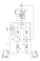
- FIG. 1 is an overall schematic diagram of a specimen testing system according to an embodiment of the present invention
- FIG. 2 is a functional block diagram of the robot control device according to the embodiment.
- FIG. 11 is a functional block diagram of a robot control device according to a modified embodiment.
- FIG. 13 is a diagram showing an example of a setting screen for inputting changes in the modified embodiment.
- the vehicle testing system 100 of this embodiment tests a vehicle or a part thereof, that is, a specimen V.
- the vehicle may be an engine vehicle, a hybrid vehicle (HV), an electric vehicle (EV), a fuel cell vehicle (FCV), a hydrogen engine vehicle, or the like.
- the specimen V may be not only a completed vehicle, but also a part of a vehicle having a vehicle pedal (at least one of an accelerator pedal V3 and a brake pedal V4) and a configuration capable of applying a running resistance by the dynamometer 2 (for example, wheels, axles, etc.).
- the vehicle testing system includes a driving robot (driving device) 2 for automatically driving the test specimen V by operating the vehicle pedals (accelerator pedal V3 or brake pedal V4, etc.) of the test specimen V, a robot control device (driving device control device) 3 for controlling the driving robot 2, a dynamometer 4 for applying a running resistance to the test specimen V driven by the driving robot 2 according to the vehicle speed of the test specimen V, and a dynamometer control device 5 for controlling the dynamometer 4.
- driving robot driving device
- driving device control device 3 for controlling the driving robot 2
- a dynamometer 4 for applying a running resistance to the test specimen V driven by the driving robot 2 according to the vehicle speed of the test specimen V
- a dynamometer control device 5 for controlling the dynamometer 4.
- the dynamometer 4 is a so-called chassis dynamometer, and has rollers 41a, 41b on which the wheels V1, V2 of the specimen V are placed, and power absorbing parts 42a, 42b such as motors connected to the rollers 41a, 41b.
- the front wheel V1 and the rear wheel V2 of the specimen V are placed on the rollers 41a, 41b, respectively, but the driving wheels of the specimen V may be placed on the rollers.
- the dynamometer 4 may be connected to each wheel (hub) or each axle of the specimen V.
- the dynamo control device 5 controls the torque of the power absorbing units 42a, 42b so that the target running resistance is determined in a predetermined running pattern. Specifically, the dynamo control device 5 controls the torque of the power absorbing units 42a, 42b so that the target running resistance corresponding to the vehicle speed of the test specimen V, which is driven by the driving robot 2 and running on the rollers 41a, 41b, is given.
- the target running resistance corresponding to the vehicle speed of the test specimen V may be calculated based on the actual speed of the test specimen V, or may be calculated based on the target vehicle speed for the test specimen V.
- the dynamo control device 5 is, for example, a computer having a CPU, memory, input/output interface, AD converter, etc., and is configured to perform its functions by the CPU and peripheral devices working together in accordance with a program stored in the memory.
- the driving robot 2 is a driving device that drives the test specimen V, and is placed, for example, on the driver's seat of the test specimen V, and is equipped with actuators 21 that respectively operate the accelerator pedal V3, brake pedal V4, shift lever (not shown), or ignition switch (not shown) of the test specimen V.
- the driving robot 2 has actuators 21 such as an accelerator actuator for depressing the accelerator pedal V3, a brake actuator for depressing the brake pedal V4, a shift lever actuator for operating the shift lever, or a switch actuator for operating the ignition switch.
- the driving robot 2 may have a clutch actuator for depressing the clutch pedal, etc., as necessary. Note that for the sake of convenience, FIG. 1 shows only one actuator without distinguishing between the above actuators.
- the robot control device 3 controls the driving robot 2, which is a driving device, and drives the test specimen V, to which a running resistance is applied by the dynamometer 4, by controlling each actuator 21 of the driving robot 2.
- the robot control device 3 is a computer having a CPU, memory, an input/output interface, an AD converter, etc., and is configured to perform its functions by the CPU and peripheral devices working together in accordance with the driving control program stored in the memory.
- the robot control device 3 of this embodiment controls each actuator 21 of the driving robot 2 based on target operation amount data, which is time series data of the target operation amount of the vehicle pedal (accelerator pedal V3 or brake pedal V4), and target vehicle speed data, which is time series data of the target vehicle speed of the test subject V.
- target operation amount data which is time series data of the target operation amount of the vehicle pedal (accelerator pedal V3 or brake pedal V4)
- target vehicle speed data which is time series data of the target vehicle speed of the test subject V.
- the target operation amount data of the accelerator pedal V3 is, for example, time series data of pedal operation amount such as the accelerator opening, accelerator depression amount, and/or accelerator pedal position of the accelerator pedal V3 obtained in a past driving test, and may be processed time series data of the pedal operation amount.
- the pedal operation amount of the accelerator pedal V3 may be a digital value from a computer on the vehicle side, a pedal position measured by a distance meter, or a pedal angle measured by an angle sensor, etc.
- the robot control device 3 also controls the brake actuator 21 based on target operation amount data, which is time series data of the target operation amount of the brake pedal V4, and target vehicle speed data, which is time series data of the target vehicle speed of the test specimen V.
- the target operation amount data of the brake pedal V4 is, for example, time series data of pedal operation amount such as the brake opening, target brake depression amount, and/or brake pedal position of the brake pedal V4 obtained in a past driving test, and may be processed time series data of the pedal operation amount.
- the pedal operation amount of the brake pedal V4 may be a digital value from a computer on the vehicle side, a pedal position measured by a distance meter, or a pedal angle measured by an angle sensor.
- the past driving tests for the above target operation amount data of the accelerator pedal V3 and the brake pedal V4 may be road driving tests, bench driving tests, or simulation driving tests. Furthermore, the target operation amount data of the accelerator pedal V3 and the target operation amount data of the brake pedal V4 may be from the same driving test, or may be from different driving tests.
- the target vehicle speed data may be, for example, time series data of the vehicle speed obtained in a past driving test in which the target operation amount data was obtained, or may be processed vehicle speed time series data.
- the target vehicle speed data may be the time series data of the vehicle speed obtained in the past driving test in which the target operation amount data of the accelerator pedal V3 was obtained, or the time series data of the vehicle speed obtained in the past driving test in which the target operation amount data of the brake pedal V4 was obtained.
- the time series data of the vehicle speed obtained in these separate past driving tests may be combined.
- the robot control device 3 uses a control algorithm of the two-degree-of-freedom control system to feedforward control each actuator 21 of the driving robot 2 based on the target operation amount data, and feedback control each actuator 21 of the driving robot 2 based on the target vehicle speed data.
- the robot control device 3 includes a first data acquisition unit 31 that acquires target operation amount data, a second data acquisition unit 32 that acquires target vehicle speed data, and a robot control unit (driving device control unit) 33 that controls the actuators 21 of the driving robot 2, such as an accelerator actuator or a brake actuator.
- a robot control unit driving device control unit
- the first data acquisition unit 31 may acquire target operation amount data from a data storage unit (not shown) provided inside or outside the robot control device 3 via a wired or wireless communication line, or may acquire target operation amount data input by a user to the robot control device 3 via an input means (not shown).
- the second data acquisition unit 32 may acquire target vehicle speed data from a data storage unit (not shown) provided inside or outside the robot control device 3 via a wired or wireless communication line, or may acquire target vehicle speed data input by the user to the robot control device 3 via an input means (not shown).
- the robot control unit 33 has a feedforward control unit 33a that performs feedforward control of the driving robot 2 based on the target operation amount data acquired by the first data acquisition unit 31, and a feedback control unit 33b that performs feedback control of the driving robot 2 based on the target vehicle speed data acquired by the second data acquisition unit 32.
- the feedforward control unit 33a obtains the accelerator depression amount Acc FF (t) or the brake depression amount Brk FF (t) of the feedforward control system from the target operation amount p(t) at the current time.
- the robot control unit 33 adds the accelerator depression amount AccFF (t) of the feedforward control unit 33a and the accelerator depression amount AccFB (t) of the feedback control unit 33b using an adder 33c. This causes the accelerator depression amount AccFF (t) of the feedforward control unit 33a to be corrected (complemented) using the accelerator depression amount AccFB (t) of the feedback control unit 33b.
- accelerator depression amount Acc FF (t) and the accelerator depression amount Acc FB (t) are added together in the adder 33c, they are each multiplied by a coefficient, whereby the accelerator actuator 21 can be controlled in accordance with a preset control ratio between feedforward control and feedback control.
- the robot control unit 33 adds the brake depression amount BrkFF (t) of the feedforward control unit 33a and the brake depression amount BrkFB (t) of the feedback control unit 33b using an adder 33c.
- the brake depression amount BrkFF (t) of the feedforward control unit 33a is corrected (complemented) using the brake depression amount BrkFB (t) of the feedback control unit 33b.
- the dynamometer 4 applies a running resistance to the test specimen V according to the vehicle speed of the test specimen V, while the driving robot (driving device) 2 is feedforward controlled based on the target operation amount data of the vehicle pedal (accelerator pedal V3 or brake pedal V4). Therefore, while applying a running resistance to the test specimen V, the vehicle pedal (accelerator pedal V3 or brake pedal V4) of the test specimen V can be controlled to the target operation amount, thereby testing the test specimen V.
- the robot control unit 33 also feedback controls the driving robot 2 based on the deviation between the target vehicle speed and the actual vehicle speed of the specimen V, so that the specimen V can be tested while controlling the vehicle pedal (accelerator pedal V3 or brake pedal V4) of the specimen V to the target operation amount and controlling the specimen V to the target vehicle speed.
- This makes it possible to test the specimen V, which has cleared a specified standard in terms of vehicle speed, while matching the accelerator operation amount or brake operation amount to previously acquired time series data.
- the specified standard is, for example, falling within a tolerance (allowable range) between the upper limit speed data and the lower limit speed data set for the time series data of the target speed.
- the feedforward control unit differentiates the target vehicle speed r(t) and inputs the differential value (acceleration) obtained by the differentiation into a driving performance map to obtain the accelerator depression amount AccFF (t) or brake depression amount BrkFF (t) of the feedforward control system, as in the conventional method (hereinafter, referred to as the conventional method).
- the driving performance map indicates the relationship between the vehicle speed, acceleration, and throttle opening obtained for each test specimen (test vehicle), and is data from which the accelerator depression amount (brake depression amount) can be obtained from the speed and acceleration (deceleration).
- a method of controlling the position of each of the accelerator pedal V3 and the brake pedal V4 using target operation amount data (the method of the present invention) or the conventional method.
- target operation amount data the method of the present invention
- the method of the present invention to control the accelerator pedal V3 and the conventional method to control the brake pedal V4.
- a vehicle e.g., an electric vehicle
- the robot control device 3 may further include a setting change unit 34 that can change the control ratio between feedforward control and feedback control.
- This setting change unit 34 can change, for example, the coefficient by which the depression amount obtained in the feedforward control unit 33a is multiplied and the coefficient by which the depression amount obtained in the feedback control unit 33b is multiplied. This makes it possible to change the control ratio.
- the specimen V can be tested with various control ratios, such as when the pedal operation amount is given priority over the vehicle speed, or when the vehicle speed is given priority over the pedal operation amount.
- the change input to the design modification unit 34 can be made using, for example, the setting screen W1 shown in FIG. 4.
- the setting screen W1 is displayed on the display by the function (screen display unit) of the robot control device 3.
- the user can change and input the priority of the pedal operation amount by sliding the slider S1 left and right with an input means such as a mouse. If the priority of the pedal operation amount is set to 0%, the setting is that the pedal operation amount is ignored and the vehicle speed is controlled. On the other hand, if the priority of the pedal operation amount is set to 100%, the setting is that the pedal operation amount is controlled and the vehicle speed is ignored.
- This change input can be made by the user inputting a numerical value into a text box or the like using an input means such as a keyboard, or a combination of sliding the slider S1 and inputting a numerical value into a text box or the like.
- the processing manner may be processing of the entire period or processing of a partial period.
- Processing of a partial period may be, for example, processing of only an acceleration period, processing of only a deceleration period, or processing of only a period during which the vehicle speed falls within a predetermined range.
- a completed vehicle was tested, but it is also possible to test an engine using an engine dynamometer, or to test a powertrain using a dynamometer, for example.
- the robot control device and the dynamo control device were each configured as separate computers, but the robot control device may be configured as one or more computers, the dynamo control device may be configured as one or more computers, or the robot control device and the dynamo control device may be configured as one computer.
- the specimen testing system may further include an exhaust gas analysis device that analyzes the exhaust gas of the specimen.
- the specimen testing system may further include a fuel consumption measurement device that measures the fuel consumption (fuel consumption) of the specimen, or an electricity consumption measurement device that measures the electricity consumption (electricity consumption).
- the present invention it is possible to test a test specimen by controlling the vehicle pedal of the test specimen to a target operation amount while applying a running resistance to the test specimen.
- Test specimen test system V: Test specimen V1: Vehicle pedal 2: Driving robot (driving device) 3...Robot control device (operating device control device) 31: Data acquisition unit 32: Data acquisition unit 33: Robot control unit (driving device control unit) 34: Setting change unit 4: Dynamometer 5: Dynamo control device
Landscapes
- Physics & Mathematics (AREA)
- General Physics & Mathematics (AREA)
- Feedback Control In General (AREA)
- Control Of Vehicle Engines Or Engines For Specific Uses (AREA)
Abstract
Description
そこで、前記データ取得部は、前記供試体の目標車速の時系列データである目標車速データを取得するものであり、前記運転装置制御部は、前記目標車速と前記供試体の実車速との偏差に基づいて前記運転装置をフィードバック制御することが望ましい。
この構成であれば、供試体の車両ペダルを目標操作量に制御しつつ、供試体を目標車速に制御しながら、供試体を試験することができる。これにより、供試体の車両ペダルを目標操作量に制御しつつ、車速に関しても所定の基準をクリアした供試体の試験を行うことができる。なお、所定の基準とは、例えば、目標速度の時系列データに対して設定された上限速度データ及び下限速度データの間であるトレランス(許容幅)に収まることである。
この構成であれば、車速よりもペダル操作量を優先的に制御する場合や、ペダル操作量よりも車速を優先的に制御する場合等の種々の制御割合で供試体を試験することができる。
ここで、アクセル開度、アクセル踏み込み量、及び/又は、アクセルペダル位置の時系列データは、例えば、過去に取得されたアクセル開度、アクセル踏み込み量、及び/又は、アクセルペダル位置の時系列データであっても良いし、それらの時系列データを加工したものであっても良い。また、それらの時系列データは、シミュレーションにより得られたものであっても良い。
ここで、ブレーキ開度、ブレーキ踏み込み量、及び/又は、ブレーキペダル位置の時系列データは、例えば、過去に取得されたブレーキ開度、ブレーキ踏み込み量、及び/又は、ブレーキペダル位置の時系列データであっても良いし、それらの時系列データを加工したものであっても良い。また、それらの時系列データは、シミュレーションにより得られたものであっても良い。
以下に、本発明に係る車両試験システムの一実施形態について、図面を参照して説明する。なお、以下に示すいずれの図についても、わかりやすくするために、適宜省略し又は誇張して模式的に描かれている。同一の構成要素については、同一の符号を付して説明を適宜省略する。
本実施形態の車両試験システム100は、車両又はその一部である供試体Vを試験するものである。ここで、車両としては、エンジン車、ハイブリッド車(HV)、電気自動車(EV)、燃料電池車(FCV)、又は、水素エンジン車等であってもよい。また、供試体Vとしては、完成車両だけでなく、車両ペダル(アクセルペダルV3又はブレーキペダルV4の少なくとも一方)と、ダイナモメータ2により走行抵抗を与えることができる構成(例えば車輪や車軸等)とを有する車両の一部であっても良い。
ダイナモメータ4は、図1に示すように、いわゆるシャシダイナモメータであり、供試体Vの車輪V1、V2が載置されるローラ41a、41bと、ローラ41a、41bに接続されたモータ等の動力吸収部42a、42bとを有している。なお、図1では、供試体Vの前輪V1及び後輪V2それぞれがローラ41a、41bに載置される構成であるが、供試体Vの駆動輪がローラに載置される構成であっても良い。その他、ダイナモメータ4は、供試体Vの各車輪(ハブ)又は各車軸に連結されたものであっても良い。
運転ロボット2は、供試体Vを運転する運転装置であり、供試体Vの例えば運転席に載置されて、供試体VのアクセルペダルV3、ブレーキペダルV4、シフトレバー(不図示)、又はイグニッションスイッチ(不図示)等をそれぞれ操作するアクチュエータ21を備えている。
このように構成した本実施形態の車両試験システム100によれば、ダイナモメータ4により供試体Vに供試体Vの車速に応じた走行抵抗を与えつつ、車両ペダル(アクセルペダルV3又はブレーキペダルV4)の目標操作量データに基づいて運転ロボット(運転装置)2をフィードフォワード制御するので、供試体Vに走行抵抗を与えつつ、供試体Vの車両ペダル(アクセルペダルV3又はブレーキペダルV4)を目標操作量に制御して、供試体Vを試験することができる。
例えば、前記実施形態では、アクセルペダルV3及びブレーキペダルV4の両方において、それぞれの目標操作量データを用いて位置を制御するものであったが、アクセルペダルV3又はブレーキペダルV4の一方において、目標操作量データを用いて位置を制御するものであっても良い。
V ・・・供試体
V1 ・・・車両ペダル
2 ・・・運転ロボット(運転装置)
3 ・・・ロボット制御装置(運転装置制御装置)
31 ・・・データ取得部
32 ・・・データ取得部
33 ・・・ロボット制御部(運転装置制御部)
34 ・・・設定変更部
4 ・・・ダイナモメータ
5 ・・・ダイナモ制御装置
Claims (9)
- 車両又はその一部である供試体を試験する供試体試験システムであって、
前記供試体の車両ペダルを操作して又は前記車両ペダルの操作に対応した操作信号を入力して、前記供試体を運転する運転装置と、
前記運転装置が運転する前記供試体の車速に応じた走行抵抗を与えるダイナモメータと、
前記車両ペダルにおける目標操作量の時系列データである目標操作量データを取得するデータ取得部と、
前記データ取得部が取得した前記目標操作量データに基づいて、前記運転装置をフィードフォワード制御する運転装置制御部とを備える、供試体試験システム。 - 前記データ取得部は、前記供試体の目標車速の時系列データである目標車速データを取得するものであり、
前記運転装置制御部は、前記目標車速と前記供試体の実車速との偏差に基づいて前記運転装置をフィードバック制御する、請求項1に記載の供試体試験システム。 - 前記運転装置制御部は、予め設定された前記フィードフォワード制御と前記フィードバック制御との制御割合に応じて、前記運転ロボットを制御する、請求項2に記載の供試体試験システム。
- 前記制御割合を設定変更できる設定変更部をさらに備える、請求項3に記載の供試体試験システム。
- 前記運転装置は、前記車両ペダルとして、アクセルペダルを操作するものであり、
前記データ取得部は、前記目標操作量データとして、アクセル開度、アクセル踏み込み量、及び/又は、アクセルペダル位置の時系列データを取得するものである、請求項1乃至4の何れか一項に記載の供試体試験システム。 - 前記運転装置は、前記車両ペダルとして、ブレーキペダルを操作するものであり、
前記データ取得部は、前記ブレーキペダルの目標操作量として、ブレーキ開度、ブレーキ踏み込み量、及び/又は、ブレーキペダル位置の時系列データを取得するものである、請求項1乃至5の何れか一項に記載の供試体試験システム。 - 供試体の車両ペダルを操作して又は前記車両ペダルの操作に対応した操作信号を入力して、前記供試体を運転する運転装置と、
前記車両ペダルにおける目標操作量の時系列データである目標操作量データを取得するデータ取得部と、
前記データ取得部が取得した前記目標操作量データに基づいて、前記運転装置をフィードフォワード制御する運転装置制御部とを備える、供試体運転システム。 - 車両又はその一部である供試体を試験する供試体試験方法であって、
前記供試体の車両ペダルを操作して又は前記車両ペダルの操作に対応した操作信号を入力して、前記供試体を運転する運転装置、及び、前記運転装置が運転する前記供試体の車速に応じた走行抵抗を与えるダイナモメータを用いて、
前記車両ペダルにおける目標操作量の時系列データに基づいて、前記運転装置をフィードフォワード制御することにより前記供試体を試験する、供試体試験方法。 - 車両又はその一部である供試体の車両ペダルを操作して又は前記車両ペダルの操作に対応した操作信号を入力して、前記供試体を運転する運転装置と、前記運転装置が運転する前記供試体の車速に応じた走行抵抗を与えるダイナモメータとを備える供試体試験システムに用いられるプログラムであって、
前記車両ペダルにおける目標操作量の時系列データである目標操作量データを取得するデータ取得部としての機能と、
前記データ取得部が取得した前記目標操作量データに基づいて、前記運転装置をフィードフォワード制御する運転装置御部としての機能とをコンピュータに備えさせる、供試体試験用プログラム。
Priority Applications (3)
| Application Number | Priority Date | Filing Date | Title |
|---|---|---|---|
| CN202480038790.4A CN121285728A (zh) | 2023-06-16 | 2024-05-20 | 被测体测试系统、被测体驾驶系统、被测体测试方法和被测体测试用程序 |
| EP24823174.8A EP4729916A1 (en) | 2023-06-16 | 2024-05-20 | Test specimen testing system, test specimen driving system, test specimen testing method, and test specimen testing program |
| JP2025527592A JPWO2024257552A1 (ja) | 2023-06-16 | 2024-05-20 |
Applications Claiming Priority (2)
| Application Number | Priority Date | Filing Date | Title |
|---|---|---|---|
| JP2023-098972 | 2023-06-16 | ||
| JP2023098972 | 2023-06-16 |
Publications (1)
| Publication Number | Publication Date |
|---|---|
| WO2024257552A1 true WO2024257552A1 (ja) | 2024-12-19 |
Family
ID=93852092
Family Applications (1)
| Application Number | Title | Priority Date | Filing Date |
|---|---|---|---|
| PCT/JP2024/018448 Ceased WO2024257552A1 (ja) | 2023-06-16 | 2024-05-20 | 供試体試験システム、供試体運転システム、供試体試験方法、及び、供試体試験用プログラム |
Country Status (4)
| Country | Link |
|---|---|
| EP (1) | EP4729916A1 (ja) |
| JP (1) | JPWO2024257552A1 (ja) |
| CN (1) | CN121285728A (ja) |
| WO (1) | WO2024257552A1 (ja) |
Citations (5)
| Publication number | Priority date | Publication date | Assignee | Title |
|---|---|---|---|---|
| JP2007155643A (ja) * | 2005-12-08 | 2007-06-21 | Toyota Motor Corp | 車両試験器における自動運転制御装置 |
| JP2013134151A (ja) | 2011-12-26 | 2013-07-08 | Horiba Ltd | 車両自動運転装置、エンジンダイナモ制御装置及び各装置に用いられる運転プログラム |
| JP2016008925A (ja) * | 2014-06-25 | 2016-01-18 | 株式会社明電舎 | 車速指令生成装置及び車速指令生成方法 |
| JP2019177859A (ja) * | 2018-03-30 | 2019-10-17 | トヨタ自動車株式会社 | 車速制御装置 |
| WO2021205767A1 (ja) * | 2020-04-10 | 2021-10-14 | 株式会社堀場製作所 | 供試体自動運転装置、供試体自動運転方法、及び、供試体試験システム |
-
2024
- 2024-05-20 CN CN202480038790.4A patent/CN121285728A/zh active Pending
- 2024-05-20 WO PCT/JP2024/018448 patent/WO2024257552A1/ja not_active Ceased
- 2024-05-20 EP EP24823174.8A patent/EP4729916A1/en active Pending
- 2024-05-20 JP JP2025527592A patent/JPWO2024257552A1/ja active Pending
Patent Citations (5)
| Publication number | Priority date | Publication date | Assignee | Title |
|---|---|---|---|---|
| JP2007155643A (ja) * | 2005-12-08 | 2007-06-21 | Toyota Motor Corp | 車両試験器における自動運転制御装置 |
| JP2013134151A (ja) | 2011-12-26 | 2013-07-08 | Horiba Ltd | 車両自動運転装置、エンジンダイナモ制御装置及び各装置に用いられる運転プログラム |
| JP2016008925A (ja) * | 2014-06-25 | 2016-01-18 | 株式会社明電舎 | 車速指令生成装置及び車速指令生成方法 |
| JP2019177859A (ja) * | 2018-03-30 | 2019-10-17 | トヨタ自動車株式会社 | 車速制御装置 |
| WO2021205767A1 (ja) * | 2020-04-10 | 2021-10-14 | 株式会社堀場製作所 | 供試体自動運転装置、供試体自動運転方法、及び、供試体試験システム |
Also Published As
| Publication number | Publication date |
|---|---|
| JPWO2024257552A1 (ja) | 2024-12-19 |
| EP4729916A1 (en) | 2026-04-22 |
| CN121285728A (zh) | 2026-01-06 |
Similar Documents
| Publication | Publication Date | Title |
|---|---|---|
| CN105092260B (zh) | 车辆测试系统、车辆部件测试装置和车辆测试方法 | |
| Oh | Evaluation of motor characteristics for hybrid electric vehicles using the hardware-in-the-loop concept | |
| CN108454607B (zh) | 基于模型预测控制(mpc)的动力系控制的转矩保护 | |
| US20090066495A1 (en) | Methods and systems for determining driver efficiency and operating modes in a hybrid vehicle | |
| CN109572665B (zh) | 基于动力系mpc的线性化模型 | |
| Albers et al. | Implementation of a vehicle-in-the-loop development and validation platform | |
| CN108622097A (zh) | 基于mpc的动力系控制中的转矩干预的协调 | |
| US9841350B2 (en) | Vehicle drive system testing apparatus | |
| US20110264428A1 (en) | System for studying a hybrid vehicle powertrain | |
| JP6429235B2 (ja) | 車両速度制御装置 | |
| CN115315621B (zh) | 被测体自动驾驶装置、被测体自动驾驶方法及被测体测试系统 | |
| Okui | Development of driving robot and driver model applied regenerative brake control of electrified vehicles | |
| JP6536726B1 (ja) | アクセル遊び測定装置、アクセル遊び測定方法、プログラム、及び媒体 | |
| WO2021193225A1 (ja) | 供試体自動運転装置、供試体試験システム、指令車速生成プログラム、及び、供試体自動運転方法 | |
| JP4546752B2 (ja) | 駆動モータを搭載した車両の走行状態模擬装置およびその方法 | |
| WO2012111110A1 (ja) | 車両用制御装置およびその製造方法 | |
| EP4729916A1 (en) | Test specimen testing system, test specimen driving system, test specimen testing method, and test specimen testing program | |
| JP7294376B2 (ja) | 車速制御装置及びドライバモデル処理装置 | |
| JP6962278B2 (ja) | ドライブロボットの車速制御装置 | |
| Pasquier et al. | Validating simulation tools for vehicle system studies using advanced control and testing procedure | |
| Gross et al. | Electronic Control of Brake and Accelerator Pedals for Precise Efficiency Testing of Electrified Vehicles | |
| JP3742577B2 (ja) | エンジン自動運転装置およびその制御方法並びに車両自動運転装置およびその制御方法 | |
| JP2023043899A (ja) | 制御装置及び制御方法 | |
| CN110466485A (zh) | 一种商用车电子机械制动器夹紧力控制系统及其控制方法 | |
| Gramlich et al. | Real Time Simulation on Test Benches under Realistic Service Conditions |
Legal Events
| Date | Code | Title | Description |
|---|---|---|---|
| 121 | Ep: the epo has been informed by wipo that ep was designated in this application |
Ref document number: 24823174 Country of ref document: EP Kind code of ref document: A1 |
|
| ENP | Entry into the national phase |
Ref document number: 2025527592 Country of ref document: JP Kind code of ref document: A |
|
| WWE | Wipo information: entry into national phase |
Ref document number: 2025527592 Country of ref document: JP |
|
| WWE | Wipo information: entry into national phase |
Ref document number: 202517123592 Country of ref document: IN |
|
| WWP | Wipo information: published in national office |
Ref document number: 202517123592 Country of ref document: IN |
|
| WWE | Wipo information: entry into national phase |
Ref document number: 2024823174 Country of ref document: EP |
|
| NENP | Non-entry into the national phase |
Ref country code: DE |
|
| ENP | Entry into the national phase |
Ref document number: 2024823174 Country of ref document: EP Effective date: 20260116 |
|
| ENP | Entry into the national phase |
Ref document number: 2024823174 Country of ref document: EP Effective date: 20260116 |
|
| ENP | Entry into the national phase |
Ref document number: 2024823174 Country of ref document: EP Effective date: 20260116 |
|
| ENP | Entry into the national phase |
Ref document number: 2024823174 Country of ref document: EP Effective date: 20260116 |
|
| WWP | Wipo information: published in national office |
Ref document number: 2024823174 Country of ref document: EP |