WO2024257522A1 - 車両管制装置および車両管制システム - Google Patents
車両管制装置および車両管制システム Download PDFInfo
- Publication number
- WO2024257522A1 WO2024257522A1 PCT/JP2024/017537 JP2024017537W WO2024257522A1 WO 2024257522 A1 WO2024257522 A1 WO 2024257522A1 JP 2024017537 W JP2024017537 W JP 2024017537W WO 2024257522 A1 WO2024257522 A1 WO 2024257522A1
- Authority
- WO
- WIPO (PCT)
- Prior art keywords
- vehicle
- control device
- vehicle control
- risk
- blind spot
- Prior art date
- Legal status (The legal status is an assumption and is not a legal conclusion. Google has not performed a legal analysis and makes no representation as to the accuracy of the status listed.)
- Ceased
Links
Images







Classifications
-
- G—PHYSICS
- G08—SIGNALLING
- G08G—TRAFFIC CONTROL SYSTEMS
- G08G1/00—Traffic control systems for road vehicles
- G08G1/09—Arrangements for giving variable traffic instructions
-
- G—PHYSICS
- G08—SIGNALLING
- G08G—TRAFFIC CONTROL SYSTEMS
- G08G1/00—Traffic control systems for road vehicles
- G08G1/16—Anti-collision systems
Definitions
- This disclosure relates to a vehicle control device and a vehicle control system.
- the infrastructure sensor information acquisition unit acquires infrastructure sensor information obtained by infrastructure sensors installed around the road detecting the surroundings of a vehicle on the road.
- the blind spot information generation unit generates blind spot information related to blind spot areas caused by obstacles when viewed from the vehicle based on the infrastructure sensor information.
- the display control unit performs control so that the blind spot information is displayed on the vehicle.
- blind spots can occur from both vehicle sensors mounted on vehicles that detect obstacles around the vehicle, and infrastructure sensors installed outside the vehicle that detect obstacles around the vehicle.
- the present disclosure provides a vehicle control device and a vehicle control system that can address the risk of blind spots occurring in both vehicle sensors mounted on a vehicle and infrastructure sensors located adjacent to the location where the vehicle is traveling.
- One aspect of the present disclosure is a vehicle control device that includes an information integration unit that generates a common blind spot map including position information of a common blind spot that is a blind spot of both a vehicle sensor that is mounted on a vehicle and detects objects around the vehicle and an infrastructure sensor that is arranged adjacent to the vehicle's driving path and detects objects around the vehicle, a risk determination unit that determines the risk of an obstructed object being present in the common blind spot based on the common blind spot map and the size of the obstructed object that may be present around the vehicle, and an entry feasibility determination unit that determines whether the vehicle can enter a risk area adjacent to the common blind spot based on the risk determination result by the risk determination unit, and transmits a stopping position before the risk area to the vehicle when the entry feasibility determination result is not possible.
- an information integration unit that generates a common blind spot map including position information of a common blind spot that is a blind spot of both a vehicle sensor that is mounted on a vehicle and detects objects around the vehicle and an infrastructure sensor that is
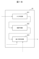
- FIG. 1 is a block diagram showing a first embodiment of a vehicle control system according to the present disclosure.
- FIG. 1B is a block diagram showing details of a risk assessment unit of the vehicle control system of FIG. 1A.
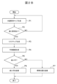
- 1B is a flowchart illustrating the operation of the vehicle control device of FIG. 1A;
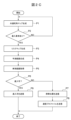
- 1B is a flowchart illustrating a modified example of the operation of the vehicle control device of FIG. 1A.
- 1B is a flowchart illustrating a modified example of the operation of the vehicle control device of FIG. 1A.
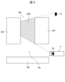
- FIG. 1B is a plan view showing a common blind spot between the vehicle sensors and the infrastructure sensors of FIG. 1A;
- FIG. 1B is a plan view showing an example of a method for defining an obstruction that may exist around the vehicle of FIG. 1A.
- FIG. 2 is a plan view illustrating the processing of a risk determination unit constituting the risk assessment unit of FIG. 1B.
- FIG. 2 is a plan view illustrating the processing of a risk determination unit constituting the risk assessment unit of FIG. 1B.
- FIG. 2 is a plan view illustrating the process of a path prediction unit constituting the risk assessment unit of FIG. 1B .
- FIG. 2 is a plan view illustrating the process of a path prediction unit constituting the risk assessment unit of FIG. 1B .
- FIG. 2 is a plan view illustrating the processing of an entry permission determination unit constituting the risk assessment unit of FIG. 1B .
- 1B is a flow diagram illustrating the operation of a vehicle control device constituting the vehicle control system of FIG. 1A.
- FIG. 1B is a plan view showing an example of a method for defining an obstruction that may exist around the vehicle of FIG. 1A.
- FIG. 2 is a plan view illustrating the processing of a risk determination unit constituting the risk assessment unit of FIG. 1B.
- FIG. 2 is a plan view illustrating the processing of a risk determination unit constituting the risk assessment unit of FIG. 1B.
- FIG. 2 is a plan view illustrating the process of a path prediction unit constituting the risk assessment unit of FIG. 1B .
- FIG. 2 is a plan view illustrating the process of a path prediction unit constituting the risk assessment unit of FIG. 1B .
- Fig. 1A is a block diagram showing a first embodiment of a vehicle control system according to the present disclosure.
- Fig. 1B is a block diagram showing details of a risk assessment unit 22 of the vehicle control system 1 of Fig. 1A. Note that Fig. 1A illustrates only one vehicle V out of multiple vehicles V for simplification.
- the vehicle control system 1 of this embodiment is composed of, for example, a vehicle control device 2 that controls multiple vehicles V, and a vehicle control device 3 mounted on each vehicle V.
- the vehicle control device 2 and vehicle control system 1 of this embodiment address the risk of blind spots occurring for both the vehicle sensors VS mounted on each of the multiple vehicles V and the infrastructure sensors IS located adjacent to the locations where each vehicle V is traveling, and improve the traveling efficiency of the vehicles V while ensuring the safety of their travel.
- the vehicle control device 2 is, for example, configured by a computer such as a network server connected to a network.
- the vehicle control device 2 has, for example, an information integration unit 21 and a risk assessment unit 22, as shown in FIG. 1A.
- the risk assessment unit 22 also has, for example, a risk determination unit 221 and an entry feasibility determination unit 223, as shown in FIG. 1B.
- the risk assessment unit 22 may further have, for example, a route prediction unit 222.
- Each of these units of the vehicle control device 2 represents each function of the vehicle control device 2 that is realized by, for example, a central processing unit (CPU) executing a program stored in a memory such as a ROM or RAM.
- CPU central processing unit
- the vehicle control device 3 is, for example, an electronic control unit (ECU) that controls the traveling of the vehicle V using the detection results of the vehicle sensor VS mounted on the vehicle V. That is, the vehicle V is, for example, an autonomous vehicle capable of autonomous driving (AD) by the vehicle control device 3. Note that the vehicle V may also be, for example, a manually driven vehicle equipped with an advanced driver assistance system (ADAS) including the vehicle control device 3.
- the vehicle management device 2 is connected to the vehicle control device 3 mounted on each vehicle V so as to be able to communicate information with them, for example, via a wireless communication line and a network.
- the vehicle sensors VS include external sensors, such as a camera, millimeter wave radar, LiDAR (laser radar), and ultrasonic sensors, that are mounted on the vehicle V and detect objects around the vehicle V.
- the vehicle sensors VS also include various sensors mounted on the vehicle V, such as a receiver for a global navigation satellite system (GNSS), a vehicle speed sensor, an acceleration sensor, an accelerator sensor, a brake sensor, a steering angle sensor, a shift position sensor, and a torque sensor.
- GNSS global navigation satellite system
- the infrastructure sensor IS is, for example, an external sensor such as a camera, millimeter wave radar, LiDAR (laser radar), or ultrasonic sensor, and is a roadside sensor that is placed adjacent to the driving path of the vehicle V and detects objects around the vehicle V.
- the infrastructure sensor IS is, for example, connected to the vehicle control device 2 via a network so that it can communicate information.
- Fig. 2A is a flowchart explaining the operation of the vehicle control device 2 of Fig. 1A.
- Figs. 2B and 2C are flowcharts explaining modified examples of the operation of the vehicle control device 2 of Fig. 1A.
- Fig. 3 is a plan view showing a common blind spot CBA between the vehicle sensor VS and the infrastructure sensor IS of Fig. 1A.
- the information integration unit 21 executes process P1 to generate a common blind spot map Mb. More specifically, the information integration unit 21 acquires the detection results of objects around the vehicle V by the vehicle sensor VS mounted on the vehicle V, for example, from the vehicle control device 3 of the vehicle V via a wireless communication line and a network.
- the information integration unit 21 also acquires detection results of objects around the vehicle V, for example, from infrastructure sensors IS adjacent to the driving path of the vehicle V. Furthermore, the information integration unit 21 integrates the detection results of the vehicle sensors VS and the infrastructure sensors IS, for example, to generate a common blind spot map Mb including position information of a common blind spot CBA that is a blind spot of both the vehicle sensors VS and the infrastructure sensors IS, as shown in FIG. 3.
- the vehicle control device 2 executes process P6 to determine whether the vehicle V can enter the risk area RA adjacent to the common blind spot CBA, as shown in FIG. 2A, for example.
- the information integration unit 21 may execute processes P2 to P5 shown in FIG. 2B and FIG. 2C after the end of process P1 and before the start of process P6.
- the information integration unit 21 determines whether or not a request to enter the risk area RA described below has been received from the vehicle V. If the information integration unit 21 determines in process P2 that an entry request has not been received (NO), it repeats the process of generating the common blind spot map Mb in process P1 at a predetermined cycle until it determines that an entry request has been received (YES). This makes it possible to update the common blind spot map Mb to the latest state until a request to enter the risk area RA is received from the vehicle V. If the vehicle control device 2 determines in process P2 that an entry request has been received (YES), it executes process P3 to generate, for example, a risk map Mr (see Figure 4C).
- FIG. 4A is a plan view showing an example of a method for determining an obstructed object HO that may exist around the vehicle V in FIG. 1A.
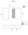
- FIGS. 4B and 4C are plan views explaining process P3 of the risk determination unit 221 constituting the risk assessment unit 22 in FIG. 1B.
- the risk determination unit 221 acquires, for example, the size of the obstructed object HO stored in the memory of the vehicle control device 2, as shown in FIG. 4A.
- the shape and size of the obstructed object HO that may be present around the vehicle V are set in advance, for example, by a user or administrator of the vehicle control system 1 and the vehicle control device 2, and stored in the memory of the vehicle control device 2.
- the obstructed object HO includes, for example, moving objects and stationary objects. Moving objects include, for example, vehicles and pedestrians. Stationary objects include, for example, parked vehicles and other obstacles OB.
- vehicle V is a trailer that transports containers at a container port
- vehicle control system 1 and vehicle control device 2 defines the trailer as an obstructed object HO, for example, as shown in FIG. 4A, and inputs the trailer's overall length L and width W, etc., as the size of the obstructed object HO into vehicle control device 2 and stores them in memory.
- the risk determination unit 221 scans the common blind spot CBA with the hidden object HO based on the common blind spot map Mb and the size of the hidden object HO, and determines whether or not there is an area in the common blind spot CBA that contains the entire hidden object HO.
- the risk determination unit 221 determines that there is an area in the common blind spot CBA that contains the entire hidden object HO, as shown in FIG. 4B, it generates a risk map Mr that includes position information of the area that contains the hidden object HO, as shown in FIG. 4C.
- the vehicle control device 2 executes a process P4 in which the route prediction unit 222 generates a predicted route ER (see FIG. 5B) of the obstructed object HO.
- the route prediction unit 222 generates a predicted route ER of the moving object as the obstructed object HO for which the risk determination unit 221 has determined that there is a risk of the object being in the common blind spot CBA.
- the route prediction unit 222 acquires high-precision map data HD of the surroundings of the vehicle V.
- the high-precision map data HD includes information such as road positions, road directions, traffic regulations, and speed limits, and is stored in the memory of the vehicle control device 2.
- the route prediction unit 222 generates a predicted route ER of the obstructed object HO as a moving object that may exist in the common blind spot CBA, as shown in FIG. 5B, based on the acquired high-precision map data HD and the risk map Mr shown in FIG. 4C.
- the vehicle control device 2 executes a process P6 for determining whether the vehicle V can enter a risk area RA adjacent to the common blind spot CBA, as shown in FIG. 2B, for example.
- the vehicle control device 2 may execute process P5 to acquire a route for the vehicle V before process P6, as shown in FIG. 2C, for example.
- the entry feasibility determination unit 223 of the vehicle control device 2 acquires the planned route VR (see FIG. 6), which is the route along which the vehicle V is scheduled to travel, from the vehicle control device 3 of the vehicle V, for example, via a wireless communication line and a network.
- the vehicle control device 2 executes process P6 to determine whether the vehicle V is permitted to enter the risk area RA adjacent to the common blind spot CBA.
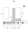
- FIG. 6 is a plan view explaining the processing of the entry feasibility determination unit 223 constituting the risk assessment unit 22 of FIG. 1B.
- the entry feasibility determination unit 223 determines whether the vehicle V can enter the risk area RA based on the risk determination result by the risk determination unit 221.
- the risk area RA is, for example, an area adjacent to an area in the common blind spot CBA where the risk determination unit 221 has determined that there is a risk of an obstructed object HO being present, as shown in FIG. 4C.
- the risk area RA is, for example, a band-shaped area through which a moving body, as an obstructed object HO that has been determined by the risk determination unit 221 to have a risk of existing in the common blind spot CBA, passes when moving along its predicted route ER, as shown in FIG. 5B.
- the entry feasibility determination unit 223 determines that entry is not permitted (NO) if the vehicle V is attempting to enter the risk area RA adjacent to an obstructed object HO that has been determined to have a risk of existing in the common blind spot CBA, as shown in FIG. 4C.
- the entry feasibility determination unit 223 determines that entry is not permitted when the vehicle V is attempting to enter a band-shaped risk area RA through which a hidden object HO, as a moving object determined to be at risk of being in the common blind spot CBA, would pass if it were to move along its predicted route ER, as shown in FIG. 5B. More specifically, the entry feasibility determination unit 223 determines that entry is not permitted when a risk area RA through which a hidden object HO, as a moving object moving along the predicted route ER, may pass, overlaps with the planned route VR of the vehicle V, as shown in FIG. 6.
- the entry feasibility determination unit 223 determines whether or not entry into the risk area RA is possible based on the planned route VR of the vehicle V and the predicted route ER of the moving body generated by the route prediction unit 222.
- the entry feasibility determination unit 223 determines in process P6 that the vehicle V cannot enter the risk area RA (NO)
- the stopping position SP is set, for example, to a position on the planned route VR of the vehicle V, before the risk area RA, as shown in FIG. 6.
- FIG. 7 is a flow diagram explaining the operation of the vehicle control device 3 constituting the vehicle control system 1 of FIG. 1A.
- the vehicle control device 3 starts the processing flow shown in FIG. 7 and executes process P31, which transmits a request to enter the risk area RA.
- the vehicle control device 2 receives an entry request from the vehicle V, it determines, for example, in process P2 shown in FIG. 2B and FIG. 2C, that there has been an entry request from the vehicle V (YES), executes the above-mentioned processes P2 to P6, and transmits the determination result of whether entry is permitted to the vehicle V.
- the vehicle control device 3 mounted on the vehicle V receives the result of the determination that entry into the risk area RA is not permitted and the stopping position SP from the vehicle control device 2, it determines that entry is not permitted (NO) in the entry possibility determination process P32 shown in FIG. 7. In this case, the vehicle control device 3 controls the travel of the vehicle V and executes process P33 to stop the vehicle V at the stopping position SP received from the vehicle control device 2.
- the entry permission determination unit 223 of the vehicle control device 2 may transmit to the vehicle V, together with the stopping position SP, a deceleration start position DSP (see FIG. 6) at which the vehicle V starts to decelerate in order to stop at the stopping position SP.
- the vehicle control device 3 controls the travel of the vehicle V so that the vehicle V decelerates from the deceleration start position DSP received from the vehicle control device 2.
- the entry permission determination unit 223 may execute process P8 of transmitting to the vehicle V a speed profile for stopping the vehicle V at the stopping position SP, as shown in FIG. 2C.
- the vehicle control device 3 controls the travel of the vehicle V so as to decelerate the vehicle V according to the speed profile received from the vehicle control device 2.
- the vehicle control device 2 ends the processing flow shown in Figures 2A to 2C and executes it repeatedly at a predetermined cycle. Also, the vehicle control device 3 ends the processing flow shown in Figure 7 and executes it repeatedly at a predetermined cycle. That is, in the above-mentioned process P7, the vehicle control device 2 transmits the stopping position SP to the vehicle V by the entry feasibility determination unit 223, and then executes process P1 to regenerate the common blind spot CBA by the information integration unit 21.
- the risk determination unit 221 re-determines the risk that an obstructed object HO exists in the common blind spot CBA, and the entry feasibility determination unit 223 re-determines entry feasibility based on the re-determination result of the risk determination unit 221 and re-transmits it to the vehicle V.
- the risk determination unit 221 determines that there is no risk that the obstructed object HO is present in the common blind spot CBA.
- the entry feasibility determination unit 223 determines that entry into the risk area RA adjacent to the common blind spot CBA is possible (YES), and executes process P9 for transmitting the determination result that entry into the risk area RA is possible to the vehicle V.
- the vehicle control device 3 When the vehicle control device 3 receives the determination result that entry into the risk area RA is permitted from the vehicle control device 2, it determines in process P32 shown in FIG. 7 that entry of the vehicle V into the risk area RA is permitted (YES), and executes process P34 to cause the vehicle V to travel along the planned route VR. After that, the vehicle control device 3 ends the process flow shown in FIG. 7 and repeats it at a predetermined cycle.
- the display control system described in Patent Document 1 can detect objects present in blind spots that are seen by vehicle sensors installed in the vehicle using infrastructure sensors installed on the road, and can display blind spot information about the blind spots on the vehicle.
- this conventional display control system does not anticipate the occurrence of areas that are blind spots for both vehicle sensors and infrastructure sensors.
- the vehicle control device 2 of this embodiment is equipped with an information integration unit 21, a risk assessment unit 221, and an entry feasibility assessment unit 223.
- the information integration unit 21 generates a common blind spot map Mb that includes position information of a common blind spot CBA that is a blind spot of both the vehicle sensor VS that is mounted on the vehicle V and detects objects around the vehicle V, and the infrastructure sensor IS that is arranged adjacent to the driving path of the vehicle V and detects objects around the vehicle V.
- the risk assessment unit 221 assesses the risk of an obstructed object HO being present in the common blind spot CBA based on the common blind spot map Mb and the size of the obstructed object HO that may be present around the vehicle V.
- the entry feasibility determination unit 223 determines whether the vehicle V can enter the risk area RA adjacent to the common blind spot CBA based on the risk determination result by the risk determination unit 221, and if the entry feasibility determination result indicates that entry is not possible, transmits a stopping position SP before the risk area RA to the vehicle V.
- the vehicle control device 2 of this embodiment can determine the risk of the presence of the hidden object HO in the common blind spot CBA by the risk determination unit 221 based on the common blind spot map Mb generated by the information integration unit 21 and the size of the hidden object HO. Therefore, when the risk determination unit 221 determines that there is no risk of the hidden object HO being present in the common blind spot CBA, the vehicle V entering the risk area RA adjacent to the common blind spot CBA can be allowed to travel without slowing down or stopping. Therefore, even when the vehicle sensor VS and the infrastructure sensor IS have a common blind spot CBA, the traveling efficiency of the vehicle V equipped with an advanced driving assistance system or the vehicle V that is an autonomous vehicle can be improved while ensuring safety.
- the entry feasibility determination unit 223 determines that the vehicle V cannot enter the risk area RA, and transmits a stopping position SP before the risk area RA to the vehicle V. This makes it possible to reliably avoid contact between the vehicle V and the obstructed object HO that may be present in the common blind spot CBA, improving safety.
- the entry feasibility determination unit 223 transmits to the vehicle V a deceleration start position DSP at which the vehicle V starts decelerating in order to stop at the stop position SP.
- the vehicle control device 2 of this embodiment can avoid sudden deceleration of the vehicle V just before the stop position SP, and can safely stop the vehicle V at the stop position SP just before the risk area RA.
- the entry feasibility determination unit 223 transmits to the vehicle V a speed profile for stopping the vehicle V at the stopping position SP.
- the vehicle control device 2 of this embodiment can not only avoid sudden deceleration of the vehicle V before the stopping position SP, but can also stop the vehicle V at the stopping position SP more safely and smoothly at a predetermined deceleration.
- the vehicle control device 2 of this embodiment further includes a route prediction unit 222 that generates a predicted route ER of a moving body as an obstructed object HO that has been determined by the risk determination unit 221 to be at risk of being in the common blind spot CBA.
- the entry feasibility determination unit 223 determines whether or not to enter the risk area RA based on the planned route VR of the vehicle V and the predicted route ER of the moving body generated by the route prediction unit 222.
- This configuration makes it possible to more reliably avoid contact between the vehicle V and the obstructed object HO, which is a moving object moving along the predicted route ER, thereby improving safety. Even if there is a risk that the obstructed object HO is present in the common blind spot CBA, for example, there may be cases where the area through which the obstructed object HO moving along the predicted route ER passes does not overlap with the area through which the vehicle V traveling along the planned route VR passes. In such cases, the entry feasibility determination unit 223 can determine whether entry into the risk area RA is possible, and the vehicle V is prevented from slowing down and stopping just before the risk area RA, thereby improving driving efficiency while ensuring the safety of the vehicle V.
- the information integration unit 21 regenerates the common blind spot map Mb. Furthermore, the risk determination unit 221 re-determines the risk that an obstructed object HO exists in the common blind spot CBA. Then, based on the re-determination result of the risk determination unit 221, the entry feasibility determination unit 223 re-determines whether or not the vehicle V can enter the risk area RA, and re-transmits the result to the vehicle V.
- the risk determination unit 221 determines that there is no risk of the obstructed object HO being present in the common blind spot CBA.
- the entry feasibility determination unit 223 determines whether entry into the risk area RA adjacent to the common blind spot CBA is possible, and can transmit the determination result that entry into the risk area RA is possible to the vehicle V. Therefore, according to the vehicle control device 2 of this embodiment, it is possible to reduce the number of times the vehicle V stops before the risk area RA, and to allow the vehicle V to travel efficiently while ensuring safety.
- the vehicle control system 1 of this embodiment also includes the vehicle control device 2 described above, and a vehicle control device 3 that is mounted on the vehicle V and transmits a request to enter the risk area RA to the vehicle control device 2.
- the entry feasibility determination unit 223 of the vehicle control device 2 receives a request to enter the risk area RA from the vehicle V, it transmits the determination result of whether entry into the risk area RA is permitted to the vehicle V.
- the vehicle control device 3 receives a determination result of no entry from the vehicle control device 2, it receives the stopping position SP from the vehicle control device 2 and stops the vehicle V at the stopping position SP.
- the vehicle control system 1 of this embodiment can have the risk assessment unit 221 of the vehicle control device 2 determine the risk of an obstructed object HO being present in the common blind spot CBA based on the common blind spot map Mb generated by the information integration unit 21 of the vehicle control device 2 and the size of the obstructed object HO. Therefore, when the risk assessment unit 221 determines that there is no risk of an obstructed object HO being present in the common blind spot CBA, the vehicle V entering the risk area RA adjacent to the common blind spot CBA can be caused to travel without being slowed down or stopped by the vehicle control device 3.
- the vehicle sensor VS and the infrastructure sensor IS have a common blind spot CBA, it is possible to improve the driving efficiency of a vehicle V equipped with an advanced driving assistance system or a vehicle V that is an autonomous vehicle while ensuring safety. Furthermore, if the risk determination unit 221 of the vehicle control device 2 determines that there is a risk that an obstructed object HO exists in the common blind spot CBA, the entry feasibility determination unit 223 of the vehicle control device 2 determines that the vehicle V cannot enter the risk area RA, and the stopping position SP before the risk area RA is transmitted to the vehicle control device 3 mounted on the vehicle V. This makes it possible to reliably avoid contact between the vehicle V and the obstructed object HO that may exist in the common blind spot CBA, thereby improving safety.
- the entry feasibility determination unit 223 of the vehicle control device 2 transmits to the vehicle V a deceleration start position DSP where the vehicle V starts to decelerate in order to stop at the stop position SP. Furthermore, the vehicle control device 3 decelerates the vehicle V from the deceleration start position DSP received from the vehicle control device 2. With this configuration, as described above, the vehicle control system 1 of this embodiment can avoid sudden deceleration of the vehicle V just before the stop position SP and can safely stop the vehicle V at the stop position SP just before the risk area RA.
- the entry feasibility determination unit 223 of the vehicle control device 2 transmits to the vehicle V a speed profile for stopping the vehicle V at the stopping position SP. Furthermore, the vehicle control device 3 decelerates the vehicle V in accordance with the speed profile received from the vehicle control device 2.
- the vehicle control system 1 of this embodiment not only makes it possible to avoid sudden deceleration of the vehicle V just before the stopping position SP, but also makes it possible to stop the vehicle V at the stopping position SP more safely and smoothly at a predetermined deceleration.
- this embodiment can provide a vehicle control device 2 and a vehicle control system 1 that can deal with the risk of blind spots occurring for both the vehicle sensor VS mounted on the vehicle V and the infrastructure sensor IS located adjacent to the location where the vehicle V is traveling.
- Fig. 8A is a plan view showing an example of a method for defining an obstructed object HO that may exist around the vehicle V in Fig. 1A.
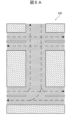
- Fig. 8B and Fig. 8C are plan views explaining the processing of a risk determination unit 221 constituting the risk evaluation unit 22 in Fig. 1B.
- the vehicle control device 2 and vehicle control system 1 of this embodiment differ from the vehicle control device 2 and vehicle control system 1 of the above-described first embodiment in that the size of a pedestrian is stored as an obstructed object HO in the memory of the vehicle control device 2.
- Other points of the vehicle control device 2 and vehicle control system 1 of this embodiment are similar to those of the vehicle control device 2 and vehicle control system 1 of the above-described first embodiment, so similar parts are given the same reference numerals and descriptions are omitted.
- the risk determination unit 221 acquires the size of a pedestrian as an obstructed object HO stored in the memory of the vehicle control device 2, for example, as shown in Figure 8A. Also, in process P3, the risk determination unit 221 scans the common blind spot CBA with the obstructed object HO based on the common blind spot map Mb and the size of the obstructed object HO, for example, as shown in Figure 8B, and determines whether or not there is an area in the common blind spot CBA that encompasses the entirety of the obstructed object HO.
- the risk determination unit 221 determines that there is an area in the common blind spot CBA that contains the entire hidden object HO, as shown in FIG. 8B, it generates a risk map Mr that includes position information of the area that contains the hidden object HO, as shown in FIG. 8C.
- the vehicle control device 2 then executes, for example, process P4 in which the path prediction unit 222 generates a predicted path for the hidden object HO.
- the path prediction unit 222 generates a predicted path for a pedestrian that is a hidden object HO that has been determined by the risk determination unit 221 to be at risk of being in the common blind spot CBA.
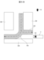
- FIGS. 9A and 9B are plan views explaining the processing of the route prediction unit 222 constituting the risk assessment unit of FIG. 1B.
- the route prediction unit 222 acquires high-precision map data HD of the surroundings of the vehicle V.
- the high-precision map data HD includes information such as road positions, sidewalk SW, and pedestrian crossing PC, and is stored in the memory of the vehicle control device 2.
- the path prediction unit 222 generates a predicted path ER of an obstructed object HO as a pedestrian that may be present in the common blind spot CBA, as shown in FIG. 9B, for example, based on the acquired high-precision map data HD and the risk map Mr shown in FIG. 8C.
- the vehicle control device 2 executes a process P6 to determine whether the vehicle V can enter a risk area RA adjacent to the common blind spot CBA, as shown in FIG. 2B, for example.
- the vehicle control device 2 and vehicle control system 1 of this embodiment can achieve the same effects as the vehicle control device 2 and vehicle control system 1 of the above-mentioned embodiment 1, even when the obstructed object HO is a pedestrian.
- Vehicle control system Vehicle control device 3
- Vehicle control device 21
- Information integration unit 221
- Risk determination unit 222
- Route prediction unit 223
- Entry possibility determination unit CBA Common blind spot
- DSP Deceleration start position ER
- Predicted route HO Obstructed object
- Infrastructure sensor RA
- Risk area SP Stop position
- V Vehicle VR Planned route VS Vehicle sensor
Landscapes
- Physics & Mathematics (AREA)
- General Physics & Mathematics (AREA)
- Traffic Control Systems (AREA)
Abstract
車両管制装置(2)は、情報統合部(21)とリスク評価部(22)とを備えている。情報統合部(21)は、車両センサ(VS)およびインフラセンサ(IS)の共通死角の位置情報を含む共通死角マップを生成する。リスク評価部(22)は、共通死角マップおよび車両(V)の周囲に存在する可能性がある被遮蔽物の大きさに基いて共通死角に被遮蔽物が存在するリスクを判定する。リスク評価部(22)は、上記リスクの判定結果に基いて共通死角に隣接するリスク領域への車両(V)の進入可否を判定し、その進入可否の判定結果が進入不可であった場合にリスク領域よりも手前の停車位置を車両(V)へ送信する。
Description
本開示は、車両管制装置および車両管制システムに関する。
従来から車両に情報が表示されるように制御を行う表示制御システムが知られている(下記特許文献1を参照)。特許文献1に記載された表示制御システムは、インフラセンサ情報取得部と、死角情報生成部と、表示制御部と、を有する(請求項1、第0006段落等)。
上記インフラセンサ情報取得部は、道路の周辺に設けられたインフラセンサが道路にある車両の周辺を検出することによって得られたインフラセンサ情報を取得する。上記死角情報生成部は、インフラセンサ情報に基づいて、車両から見たときに障害物により死角となる死角領域に関する死角情報を生成する。上記表示制御部は、死角情報が車両に表示されるように制御を行う。
たとえば、多数のコンテナが集積されるコンテナ港湾では、コンテナ船から降ろされたコンテナが新たに集積されたり、集積されたコンテナがトレーラに積載されて搬出されたりすることで、障害物の配置が頻繁に変更される。このような場所では、車両に搭載されて車両の周囲の障害物を検出する車両センサと、車両の外部に配置されて車両の周囲の障害物を検出するインフラセンサの双方から見て死角になる領域が発生することがある。
上記特許文献1に記載された表示制御システムは、車両に設けられた車両センサから見て死角になる死角領域に存在する物体を道路に設けられたインフラセンサによって検出して、死角領域に関する死角情報を車両に表示させることができる。しかし、この従来の表示制御システムは、車両センサとインフラセンサの双方の死角になる領域が発生することを想定していない。
本開示は、車両に搭載される車両センサとその車両が走行する場所に隣接して配置されるインフラセンサの双方の死角となる領域が発生する場合のリスクに対処可能な車両管制装置および車両管制システムを提供する。
本開示の一態様は、車両に搭載されて該車両の周囲の物体を検出する車両センサおよび該車両の走行経路に隣接して配置されて該車両の周囲の物体を検出するインフラセンサの双方の死角となる共通死角の位置情報を含む共通死角マップを生成する情報統合部と、前記共通死角マップおよび前記車両の周囲に存在する可能性がある被遮蔽物の大きさに基いて前記共通死角に前記被遮蔽物が存在するリスクを判定するリスク判定部と、前記リスク判定部による前記リスクの判定結果に基いて前記共通死角に隣接するリスク領域への前記車両の進入可否を判定し、前記進入可否の判定結果が進入不可であった場合に前記リスク領域よりも手前の停車位置を前記車両へ送信する進入可否判定部と、を備えることを特徴とする車両管制装置である。
本開示の上記一態様によれば、車両に搭載される車両センサとその車両が走行する場所に隣接して配置されるインフラセンサの双方の死角となる領域が発生する場合のリスクに対処可能な車両管制装置および車両管制システムを提供することができる。
以下、図面を参照して本開示に係る車両管制装置および車両管制システムの実施形態を説明する。
[実施形態1]
図1Aは、本開示に係る車両管制システムの実施形態1を示すブロック図である。図1Bは、図1Aの車両管制システム1のリスク評価部22の詳細を示すブロック図である。なお、図1Aでは、簡略化のため複数の車両Vのうち1台の車両Vのみを図示している。
図1Aは、本開示に係る車両管制システムの実施形態1を示すブロック図である。図1Bは、図1Aの車両管制システム1のリスク評価部22の詳細を示すブロック図である。なお、図1Aでは、簡略化のため複数の車両Vのうち1台の車両Vのみを図示している。
本実施形態の車両管制システム1は、たとえば、複数の車両Vを管制する車両管制装置2と、各々の車両Vに搭載される車両制御装置3とによって構成される。本実施形態の車両管制装置2および車両管制システム1は、以下に説明するように、複数の車両Vの各々に搭載される車両センサVSと、各々の車両Vが走行する場所に隣接して配置されるインフラセンサISの双方の死角となる領域が発生する場合のリスクに対処し、車両Vの走行の安全性を確保しながら走行効率を改善する。
車両管制装置2は、たとえば、ネットワークに接続されるネットワークサーバなどのコンピュータによって構成されている。車両管制装置2は、たとえば、図1Aに示すように、情報統合部21と、リスク評価部22とを有している。また、リスク評価部22は、たとえば、図1Bに示すように、リスク判定部221と、進入可否判定部223とを備えている。また、リスク評価部22は、たとえば、経路予測部222をさらに備えてもよい。これら車両管制装置2の各部は、たとえば、中央処理装置(CPU)によってROMやRAMなどのメモリに格納されたプログラムを実行することで実現される車両管制装置2の各機能を表している。
車両制御装置3は、たとえば、車両Vに搭載された車両センサVSの検出結果を用いて車両Vの走行を制御する電子制御装置(ECU)である。すなわち、車両Vは、たとえば、車両制御装置3による自動運転(AD)が可能な自動運転車である。なお、車両Vは、たとえば、車両制御装置3を含む高度運転支援システム(ADAS)を備えた手動運転車であってもよい。車両管制装置2は、たとえば、無線通信回線およびネットワークを介して、各々の車両Vに搭載された車両制御装置3と情報通信可能に接続されている。
車両センサVSは、たとえば、カメラ、ミリ波レーダ、LiDAR(レーザレーダ)、超音波センサなど、車両Vに搭載されてその車両Vの周囲の物体を検出する外界センサを含む。また、車両センサVSは、たとえば、全球測位衛星システム(GNSS)の受信機、車速センサ、加速度センサ、アクセルセンサ、ブレーキセンサ、操舵角センサ、シフトポジションセンサ、トルクセンサなど、車両Vに搭載される各種のセンサを含む。
インフラセンサISは、たとえば、カメラ、ミリ波レーダ、LiDAR(レーザレーダ)、超音波センサなどの外界センサであり、車両Vの走行経路に隣接して配置されてその車両Vの周囲の物体を検出する路側センサである。インフラセンサISは、たとえば、ネットワークを介して車両管制装置2と情報通信可能に接続されている。
以下、図2Aから図7までを参照して、本実施形態の車両管制システム1の動作を説明する。図2Aは、図1Aの車両管制装置2の動作を説明するフローチャートである。図2Bおよび図2Cは、図1Aの車両管制装置2の動作の変形例を説明するフローチャートである。図3は、図1Aの車両センサVSとインフラセンサISとの共通死角CBAを示す平面図である。
車両管制装置2は、図2Aから図2Cに示す処理P1フローを開始すると、情報統合部21によって共通死角マップMbを生成する処理P1を実行する。より具体的には、情報統合部21は、たとえば、車両Vの車両制御装置3から無線通信回線およびネットワークを介して、その車両Vに搭載された車両センサVSによるその車両Vの周囲の物体の検出結果を取得する。
また、情報統合部21は、たとえば、その車両Vの走行経路に隣接するインフラセンサISから、その車両Vの周囲の物体の検出結果を取得する。さらに、情報統合部21は、たとえば、車両センサVSの検出結果とインフラセンサISの検出結果を統合して、図3に示すように、車両センサVSおよびインフラセンサISの双方の死角となる共通死角CBAの位置情報を含む共通死角マップMbを生成する。
次に、車両管制装置2は、たとえば、図2Aに示すように、共通死角CBAに隣接するリスク領域RAへの車両Vの進入可否を判定する処理P6を実行する。なお、情報統合部21は、処理P1の終了後、処理P6の開始前に、図2Bおよび図2Cに示す処理P2から処理P5を実行してもよい。
処理P2において、情報統合部21は、車両Vから後述するリスク領域RAへの進入要求を受信したか否かを判定する。情報統合部21は、処理P2で進入要求を未受信であること(NO)を判定すると、進入要求を受信したこと(YES)が判定されるまで、処理P1で共通死角マップMbを生成する処理を所定の周期で繰り返す。これにより、車両Vからリスク領域RAへの進入要求を受信するまで、共通死角マップMbを最新の状態に更新することができる。車両管制装置2は、処理P2で進入要求を受信したこと(YES)を判定すると、たとえば、リスクマップMr(図4C参照)を生成する処理P3を実行する。
図4Aは、図1Aの車両Vの周囲に存在し得る被遮蔽物HOの規定方法の一例を示す平面図である。図4Bおよび図4Cは、図1Bのリスク評価部22を構成するリスク判定部221の処理P3を説明する平面図である。処理P3において、リスク判定部221は、たとえば、図4Aに示すように、車両管制装置2のメモリに格納された被遮蔽物HOの大きさを取得する。
車両Vの周囲に存在する可能性がある被遮蔽物HOの形状および大きさは、たとえば、車両管制システム1および車両管制装置2のユーザまたは管理者によってあらかじめ設定されて車両管制装置2のメモリに格納される。被遮蔽物HOは、たとえば、移動体と静止物を含む。移動体は、たとえば、車両および歩行者を含む。静止物は、たとえば、駐車車両やその他の障害物OBを含む。
たとえば、車両Vがコンテナ港湾でコンテナを搬出するトレーラである場合、車両Vの周囲には他のトレーラが存在する可能性がある。そのため、車両管制システム1および車両管制装置2のユーザまたは管理者は、たとえば、図4Aに示すように、被遮蔽物HOとしてトレーラを規定し、被遮蔽物HOの大きさとして、トレーラの全長Lや幅Wなどを車両管制装置2に入力してメモリに格納する。
処理P3において、リスク判定部221は、たとえば、図4Bに示すように、共通死角マップMbと被遮蔽物HOの大きさに基いて、共通死角CBAを被遮蔽物HOで走査し、共通死角CBAにおける被遮蔽物HOの全体を包含する領域の有無を判定する。リスク判定部221は、図4Bに示すように、共通死角CBAに被遮蔽物HOの全体を包含する領域があることを判定すると、図4Cに示すように、その被遮蔽物HOを包含する領域の位置情報を含むリスクマップMrを生成する。
その後、車両管制装置2は、たとえば、経路予測部222によって被遮蔽物HOの予測経路ER(図5B参照)を生成する処理P4を実行する。この処理P4において、経路予測部222は、リスク判定部221によって共通死角CBAに存在するリスクが判定された被遮蔽物HOとしての移動体の予測経路ERを生成する。
図5Aおよび図5Bは、図1Bのリスク評価部22を構成する経路予測部222の処理を説明する平面図である。経路予測部222は、車両Vの周囲の高精度地図データHDを取得する。高精度地図データHDは、たとえば、道路位置、道路方向、交通規制、速度制限などの情報を含み、車両管制装置2のメモリに格納されている。さらに、経路予測部222は、たとえば、取得した高精度地図データHDと、図4Cに示すリスクマップMrと、に基いて、図5Bに示すように、共通死角CBAに存在し得る移動体としての被遮蔽物HOの予測経路ERを生成する。その後、車両管制装置2は、たとえば、図2Bに示すように、共通死角CBAに隣接するリスク領域RAへの車両Vの進入可否を判定する処理P6を実行する。
なお、車両管制装置2は、たとえば、図2Cに示すように、処理P6の前に、車両Vの経路を取得する処理P5を実行してもよい。この処理P5において、車両管制装置2の進入可否判定部223は、たとえば、車両Vの車両制御装置3から、無線通信回線およびネットワークを介して、車両Vが走行を予定している経路である予定経路VR(図6参照)を取得する。その後、車両管制装置2は、共通死角CBAに隣接するリスク領域RAへの車両Vの進入可否を判定する処理P6を実行する。
図6は、図1Bのリスク評価部22を構成する進入可否判定部223の処理を説明する平面図である。図2Aから図2Cに示す処理P6において、進入可否判定部223は、リスク判定部221によるリスクの判定結果に基いてリスク領域RAへの車両Vの進入可否を判定する。リスク領域RAは、たとえば、図4Cに示すように、リスク判定部221が共通死角CBAにおいて被遮蔽物HOが存在するリスクを判定した領域に隣接する領域である。
より具体的には、リスク領域RAは、たとえば、図5Bに示すように、リスク判定部221によって共通死角CBAに存在するリスクが判定された被遮蔽物HOとしての移動体が、その予測経路ERに沿って移動した場合に通過する帯状の領域である。進入可否判定部223は、処理P6において、図4Cに示すような共通死角CBAに存在するリスクがあることが判定された被遮蔽物HOに隣接するリスク領域RAへ車両Vが進入しようとしている場合に、進入不可(NO)を判定する。
より具体的には、進入可否判定部223は、たとえば、図5Bに示すように、共通死角CBAに存在するリスクが判定された移動体としての被遮蔽物HOがその予測経路ERに沿って移動した場合に通過する帯状のリスク領域RAへ車両Vが進入しようとしている場合に、進入不可を判定する。より詳細には、進入可否判定部223は、たとえば、図6に示すように、予測経路ERに沿って移動する移動体としての被遮蔽物HOが通過する可能性があるリスク領域RAと車両Vの予定経路VRとが重なる場合に、進入不可を判定する。
すなわち、進入可否判定部223は、たとえば、リスク判定部221によって共通死角CBAに移動体が存在するリスクが判定された場合に、車両Vの予定経路VRと経路予測部222によって生成された移動体の予測経路ERとに基いて、リスク領域RAへの進入可否を判定する。進入可否判定部223は、処理P6において車両Vのリスク領域RAへの進入不可(NO)を判定すると、車両Vへ停車位置SPを送信する処理P7を実行する。停車位置SPは、たとえば、図6に示すように、車両Vの予定経路VR上で、リスク領域RAよりも手前の位置に設定される。
図7は、図1Aの車両管制システム1を構成する車両制御装置3の動作を説明するフロー図である。車両制御装置3は、たとえば、予定経路VRの前方にリスク領域RAが存在する場合に、図7に示す処理フローを開始して、リスク領域RAへの進入要求を送信する処理P31を実行する。車両管制装置2は、車両Vから進入要求を受信すると、たとえば、図2Bおよび図2Cに示す処理P2において車両Vから進入要求があったこと(YES)を判定し、前述の処理P2から処理P6までを実行して、車両Vへ進入可否の判定結果を送信する。
車両Vに搭載された車両制御装置3は、車両管制装置2からリスク領域RAへの進入不可の判定結果と停車位置SPを受信すると、図7に示す進入可否判定処理P32において、進入不可(NO)を判定する。この場合、車両制御装置3は、車両Vの走行を制御して、車両管制装置2から受信した停車位置SPに車両Vを停車させる処理P33を実行する。
なお、車両管制装置2の進入可否判定部223は、前述の停車位置SPを送信する処理P7において、停車位置SPとともに、車両Vが停車位置SPで停車するために減速を開始する減速開始位置DSP(図6参照)を車両Vへ送信してもよい。この場合、車両制御装置3は、車両Vを停車位置SPに停車させる処理P33において、車両管制装置2から受信した減速開始位置DSPから車両Vを減速させるように、車両Vの走行を制御する。
また、進入可否判定部223は、前述の停車位置SPを送信する処理P7の終了後、図2Cに示すように、車両Vが停車位置SPで停車するための速度プロファイルを車両Vへ送信する処理P8を実行してもよい。この場合、車両制御装置3は、車両Vを停車位置SPに停車させる処理P33において、車両管制装置2から受信した速度プロファイルに従って車両Vを減速させるように、車両Vの走行を制御する。
その後、車両管制装置2は、図2Aから図2Cに示す処理フローを終了させて所定の周期で繰り返し実行する。また、車両制御装置3は、図7に示す処理フローを終了させて所定の周期で繰り返し実行する。すなわち、車両管制装置2は、前述の処理P7において、進入可否判定部223によって車両Vへ停車位置SPを送信した後に、処理P1を実行して情報統合部21によって共通死角CBAを再生成する。また、リスク判定部221は、共通死角CBAに被遮蔽物HOが存在するリスクを再判定し、進入可否判定部223は、リスク判定部221の再判定結果に基いて進入可否を再判定して車両Vへ再送信する。
これにより、車両Vが減速して停車位置SPに停車するまでの間に、車両センサVSの死角が減少して共通死角CBAが被遮蔽物HOの大きさよりも小さくなると、リスク判定部221は、共通死角CBAに被遮蔽物HOが存在するリスクがないことを判定する。その結果、進入可否判定部223は、進入可否を判定する処理P6で、共通死角CBAに隣接するリスク領域RAへの進入可(YES)を判定し、車両Vへリスク領域RAへの進入可の判定結果を送信する処理P9を実行する。
車両制御装置3は、車両管制装置2からリスク領域RAへの進入可の判定結果を受信すると、図7に示す処理P32において、車両Vのリスク領域RAへの進入可(YES)を判定し、車両Vを予定経路VRに沿って走行させる処理P34を実行する。その後、車両制御装置3は、図7に示す処理フローを終了させ、所定の周期で繰り返す。
以下、本実施形態の車両管制システム1および車両管制装置2の作用を説明する。
図3に示すように、たとえば、多数のコンテナなどの障害物OBが集積されるコンテナ港湾では、コンテナ船から降ろされたコンテナが新たに集積されたり、集積されたコンテナがトレーラに積載されて搬出されたりすることで、障害物OBの配置が頻繁に変更される。このような場所では、車両Vに搭載されて車両Vの周囲の障害物OBを検出する車両センサVSと、車両Vの外部に配置されて車両Vの周囲の障害物OBを検出するインフラセンサISの双方から見て死角になる領域が発生することがある。
上記特許文献1に記載された表示制御システムは、車両に設けられた車両センサから見て死角になる死角領域に存在する物体を道路に設けられたインフラセンサによって検出して、死角領域に関する死角情報を車両に表示させることができる。しかし、この従来の表示制御システムは、車両センサとインフラセンサの双方の死角になる領域が発生することを想定していない。
これに対し、本実施形態の車両管制装置2は、情報統合部21と、リスク判定部221と、進入可否判定部223とを備えている。情報統合部21は、車両Vに搭載されてその車両Vの周囲の物体を検出する車両センサVS、および、その車両Vの走行経路に隣接して配置されてその車両Vの周囲の物体を検出するインフラセンサISの双方の死角となる共通死角CBAの位置情報を含む共通死角マップMbを生成する。リスク判定部221は、共通死角マップMbおよび車両Vの周囲に存在する可能性がある被遮蔽物HOの大きさに基いて共通死角CBAに被遮蔽物HOが存在するリスクを判定する。進入可否判定部223は、リスク判定部221による上記リスクの判定結果に基いて共通死角CBAに隣接するリスク領域RAへの車両Vの進入可否を判定し、その進入可否の判定結果が進入不可であった場合にリスク領域RAよりも手前の停車位置SPを車両Vへ送信する。
このような構成により、本実施形態の車両管制装置2は、情報統合部21が生成した共通死角マップMbと被遮蔽物HOの大きさに基いて、リスク判定部221が共通死角CBAに被遮蔽物HOが存在するリスクを判定することができる。そのため、リスク判定部221によって共通死角CBAに被遮蔽物HOが存在するリスクがないことが判定された場合には、共通死角CBAに隣接するリスク領域RAに進入する車両Vを減速および停車させることなく走行させることができる。したがって、車両センサVSとインフラセンサISが共通死角CBAを有する場合でも、安全性を確保しつつ、高度運転支援システムを備えた車両V、または、自動運転車である車両Vの走行効率を向上させることができる。また、リスク判定部221によって共通死角CBAに被遮蔽物HOが存在するリスクがあることが判定された場合には、進入可否判定部223によって車両Vのリスク領域RAへの進入不可が判定され、車両Vへリスク領域RAよりも手前の停車位置SPが送信される。これにより、共通死角CBAに存在する可能性がある被遮蔽物HOと車両Vとの接触を確実に回避して安全性を向上させることが可能になる。
また、本実施形態の車両管制装置2において、進入可否判定部223は、車両Vが停車位置SPで停車するために減速を開始する減速開始位置DSPを車両Vへ送信する。このような構成により、本実施形態の車両管制装置2によれば、停車位置SPの手前での車両Vの急な減速を回避して、車両Vをリスク領域RAの手前の停車位置SPに安全に停車させることができる。
また、本実施形態の車両管制装置2において、進入可否判定部223は、車両Vが停車位置SPで停車するための速度プロファイルを車両Vへ送信する。このような構成により、本実施形態の車両管制装置2によれば、停車位置SPの手前での車両Vの急な減速を回避することができるだけでなく、所定の減速度でより安全かつ円滑に車両Vを停車位置SPに停車させることができる。
また、本実施形態の車両管制装置2は、リスク判定部221によって共通死角CBAに存在するリスクが判定された被遮蔽物HOとしての移動体の予測経路ERを生成する経路予測部222をさらに備えている。進入可否判定部223は、リスク判定部221によって共通死角CBAに移動体が存在するリスクが判定された場合に、車両Vの予定経路VRと経路予測部222によって生成された移動体の予測経路ERとに基いてリスク領域RAへの進入可否を判定する。
このような構成により、予測経路ERを移動する移動体である被遮蔽物HOと車両Vとの接触をより確実に回避して安全性を向上させることができる。また、共通死角CBAに被遮蔽物HOが存在するリスクある場合でも、たとえば、予測経路ERに沿って移動する被遮蔽物HOが通過する領域と、予定経路VRに沿って走行する車両Vが通過する領域とが重ならない場合がある。その場合、進入可否判定部223は、リスク領域RAへの進入可を判定することができ、車両Vがリスク領域RAの手前で減速および停車することが回避され、車両Vの安全性を確保しつつ走行効率を向上させることができる。
また、本実施形態の車両管制装置2では、進入可否判定部223による車両Vへの停車位置SPの送信後に、情報統合部21は、共通死角マップMbを再生成する。また、リスク判定部221は、共通死角CBAに被遮蔽物HOが存在するリスクを再判定する。そして、進入可否判定部223は、リスク判定部221の再判定結果に基いて車両Vのリスク領域RAへの進入可否を再判定して車両Vへ再送信する。
このような構成により、前述のように、車両Vが前進して車両センサVSの死角が減少し、共通死角CBAが被遮蔽物HOの大きさよりも小さくなると、リスク判定部221によって共通死角CBAに被遮蔽物HOが存在するリスクがないことが判定される。その結果、進入可否判定部223は、共通死角CBAに隣接するリスク領域RAへの進入可を判定し、車両Vへリスク領域RAへの進入可の判定結果を送信することができる。したがって、本実施形態の車両管制装置2によれば、車両Vがリスク領域RAの手前で停車することを減少させ、安全性を確保しつつ車両Vを効率よく走行させることが可能になる。
また、本実施形態の車両管制システム1は、前述の車両管制装置2と、車両Vに搭載されて車両管制装置2に対してリスク領域RAへの進入要求を送信する車両制御装置3と、を含む。また、車両管制装置2の進入可否判定部223は、車両Vからリスク領域RAへの進入要求を受信すると、車両Vへリスク領域RAへの進入可否の判定結果を送信する。また。車両制御装置3は、車両管制装置2から進入不可の判定結果を受信した場合に、車両管制装置2から停車位置SPを受信して車両Vを停車位置SPに停車させる。
このような構成により、本実施形態の車両管制システム1は、車両管制装置2の情報統合部21が生成した共通死角マップMbと被遮蔽物HOの大きさに基いて、車両管制装置2のリスク判定部221が共通死角CBAに被遮蔽物HOが存在するリスクを判定することができる。そのため、リスク判定部221によって共通死角CBAに被遮蔽物HOが存在するリスクがないことが判定された場合には、共通死角CBAに隣接するリスク領域RAに進入する車両Vを車両制御装置3によって減速および停車させることなく走行させることができる。したがって、車両センサVSとインフラセンサISが共通死角CBAを有する場合でも、安全性を確保しつつ、高度運転支援システムを備えた車両V、または、自動運転車である車両Vの走行効率を向上させることができる。また、車両管制装置2のリスク判定部221によって共通死角CBAに被遮蔽物HOが存在するリスクがあることが判定された場合には、車両管制装置2の進入可否判定部223によって車両Vのリスク領域RAへの進入不可が判定され、車両Vに搭載された車両制御装置3へリスク領域RAよりも手前の停車位置SPが送信される。これにより、共通死角CBAに存在する可能性がある被遮蔽物HOと車両Vとの接触を確実に回避して安全性を向上させることが可能になる。
また、本実施形態の車両管制システム1において、車両管制装置2の進入可否判定部223は、車両Vが停車位置SPで停車するために減速を開始する減速開始位置DSPを車両Vへ送信する。また、車両制御装置3は、車両管制装置2から受信した減速開始位置DSPから車両Vを減速させる。このような構成により、前述のように、本実施形態の車両管制システム1によれば、停車位置SPの手前での車両Vの急な減速を回避して、車両Vをリスク領域RAの手前の停車位置SPに安全に停車させることができる。
また、本実施形態の車両管制システム1において、車両管制装置2の進入可否判定部223は、車両Vが停車位置SPで停車するための速度プロファイルを車両Vへ送信する。また、車両制御装置3は、車両管制装置2から受信した速度プロファイルに従って車両Vを減速させる。このような構成により、前述のように、本実施形態の車両管制システム1によれば、停車位置SPの手前での車両Vの急な減速を回避することができるだけでなく、所定の減速度でより安全かつ円滑に車両Vを停車位置SPに停車させることができる。
以上説明したように、本実施形態によれば、車両Vに搭載される車両センサVSとその車両Vが走行する場所に隣接して配置されるインフラセンサISの双方の死角となる領域が発生する場合のリスクに対処可能な車両管制装置2および車両管制システム1を提供することができる。
[実施形態2]
以下、図8Aから図9Bまでを参照して、本開示に係る車両管制装置および車両管制システムの実施形態2を説明する。図8Aは、図1Aの車両Vの周囲に存在し得る被遮蔽物HOの規定方法の一例を示す平面図である。図8Bおよび図8Cは、図1Bのリスク評価部22を構成するリスク判定部221の処理を説明する平面図である。
以下、図8Aから図9Bまでを参照して、本開示に係る車両管制装置および車両管制システムの実施形態2を説明する。図8Aは、図1Aの車両Vの周囲に存在し得る被遮蔽物HOの規定方法の一例を示す平面図である。図8Bおよび図8Cは、図1Bのリスク評価部22を構成するリスク判定部221の処理を説明する平面図である。
本実施形態の車両管制装置2および車両管制システム1は、車両管制装置2のメモリに被遮蔽物HOとして歩行者の大きさが格納されている点で、前述の実施形態1の車両管制装置2および車両管制システム1と異なっている。本実施形態の車両管制装置2および車両管制システム1のその他の点は、前述の実施形態1の車両管制装置2および車両管制システム1と同様であるので、同様の部分には同一の符号を付して説明を省略する。
前述の図2Bおよび図2Cに示す処理P3において、リスク判定部221は、たとえば、図8Aに示すように、車両管制装置2のメモリに格納された被遮蔽物HOとしての歩行者の大きさを取得する。また、処理P3において、リスク判定部221は、たとえば、図8Bに示すように、共通死角マップMbと被遮蔽物HOの大きさに基いて、共通死角CBAを被遮蔽物HOで走査し、共通死角CBAにおける被遮蔽物HOの全体を包含する領域の有無を判定する。
リスク判定部221は、図8Bに示すように、共通死角CBAに被遮蔽物HOの全体を包含する領域があることを判定すると、図8Cに示すように、その被遮蔽物HOを包含する領域の位置情報を含むリスクマップMrを生成する。その後、車両管制装置2は、たとえば、経路予測部222によって被遮蔽物HOの予測経路を生成する処理P4を実行する。この処理P4において、経路予測部222は、リスク判定部221によって共通死角CBAに存在するリスクが判定された被遮蔽物HOとしての歩行者の予測経路を生成する。
図9Aおよび図9Bは、図1Bのリスク評価部を構成する経路予測部222の処理を説明する平面図である。経路予測部222は、車両Vの周囲の高精度地図データHDを取得する。高精度地図データHDは、たとえば、道路位置、歩道SW、横断歩道PCなどの情報を含み、車両管制装置2のメモリに格納されている。
さらに、経路予測部222は、たとえば、取得した高精度地図データHDと、図8Cに示すリスクマップMrと、に基いて、図9Bに示すように、共通死角CBAに存在し得る歩行者としての被遮蔽物HOの予測経路ERを生成する。その後、車両管制装置2は、たとえば、図2Bに示すように、共通死角CBAに隣接するリスク領域RAへの車両Vの進入可否を判定する処理P6を実行する。
このような構成により、本実施形態の車両管制装置2および車両管制システム1によれば、被遮蔽物HOが歩行者である場合でも、前述の実施形態1の車両管制装置2および車両管制システム1と同様の効果を奏することができる。
以上、図面を用いて本開示に係る車両管制装置および車両管制システムの実施形態を詳述してきたが、具体的な構成はこの実施形態に限定されるものではなく、本開示の要旨を逸脱しない範囲における設計変更等があっても、それらは本開示に含まれるものである。
1 車両管制システム
2 車両管制装置
3 車両制御装置
21 情報統合部
221 リスク判定部
222 経路予測部
223 進入可否判定部
CBA 共通死角
DSP 減速開始位置
ER 予測経路
HO 被遮蔽物
IS インフラセンサ
RA リスク領域
SP 停車位置
V 車両
VR 予定経路
VS 車両センサ
2 車両管制装置
3 車両制御装置
21 情報統合部
221 リスク判定部
222 経路予測部
223 進入可否判定部
CBA 共通死角
DSP 減速開始位置
ER 予測経路
HO 被遮蔽物
IS インフラセンサ
RA リスク領域
SP 停車位置
V 車両
VR 予定経路
VS 車両センサ
Claims (8)
- 車両に搭載されて該車両の周囲の物体を検出する車両センサおよび該車両の走行経路に隣接して配置されて該車両の周囲の物体を検出するインフラセンサの双方の死角となる共通死角の位置情報を含む共通死角マップを生成する情報統合部と、
前記共通死角マップおよび前記車両の周囲に存在する可能性がある被遮蔽物の大きさに基いて前記共通死角に前記被遮蔽物が存在するリスクを判定するリスク判定部と、
前記リスク判定部による前記リスクの判定結果に基いて前記共通死角に隣接するリスク領域への前記車両の進入可否を判定し、前記進入可否の判定結果が進入不可であった場合に前記リスク領域よりも手前の停車位置を前記車両へ送信する進入可否判定部と、
を備えることを特徴とする車両管制装置。 - 前記進入可否判定部は、前記車両が前記停車位置で停車するために減速を開始する減速開始位置を前記車両へ送信することを特徴とする請求項1に記載の車両管制装置。
- 前記進入可否判定部は、前記車両が前記停車位置で停車するための速度プロファイルを前記車両へ送信することを特徴とする請求項1に記載の車両管制装置。
- 前記リスク判定部によって前記共通死角に存在するリスクが判定された前記被遮蔽物としての移動体の予測経路を生成する経路予測部をさらに備え、
前記進入可否判定部は、前記リスク判定部によって前記共通死角に前記移動体が存在するリスクが判定された場合に、前記車両の予定経路と前記経路予測部によって生成された前記移動体の予測経路とに基いて前記リスク領域への前記進入可否を判定することを特徴とする請求項1に記載の車両管制装置。 - 前記進入可否判定部による前記車両への前記停車位置の送信後に、
前記情報統合部は、前記共通死角マップを再生成し、
前記リスク判定部は、前記共通死角に前記被遮蔽物が存在するリスクを再判定し、
前記進入可否判定部は、前記リスク判定部の再判定結果に基いて前記進入可否を再判定して前記車両へ再送信することを特徴とする請求項1に記載の車両管制装置。 - 請求項1に記載の車両管制装置と、前記車両に搭載されて前記車両管制装置に対して前記リスク領域への進入要求を送信する車両制御装置と、を含む車両管制システムであって、
前記車両管制装置の前記進入可否判定部は、前記車両から前記進入要求を受信すると前記車両へ前記進入可否の判定結果を送信し、
前記車両制御装置は、前記車両管制装置から前記進入不可の判定結果を受信した場合に、前記車両管制装置から前記停車位置を受信して前記車両を前記停車位置に停車させることを特徴とする車両管制システム。 - 前記車両管制装置の前記進入可否判定部は、前記車両が前記停車位置で停車するために減速を開始する減速開始位置を前記車両へ送信し、
前記車両制御装置は、前記車両管制装置から受信した前記減速開始位置から前記車両を減速させることを特徴とする請求項6に記載の車両管制システム。 - 前記車両管制装置の前記進入可否判定部は、前記車両が前記停車位置で停車するための速度プロファイルを前記車両へ送信し、
前記車両制御装置は、前記車両管制装置から受信した前記速度プロファイルに従って前記車両を減速させることを特徴とする請求項6に記載の車両管制システム。
Applications Claiming Priority (2)
| Application Number | Priority Date | Filing Date | Title |
|---|---|---|---|
| JP2023-098415 | 2023-06-15 | ||
| JP2023098415A JP2024179512A (ja) | 2023-06-15 | 2023-06-15 | 車両管制装置および車両管制システム |
Publications (1)
| Publication Number | Publication Date |
|---|---|
| WO2024257522A1 true WO2024257522A1 (ja) | 2024-12-19 |
Family
ID=93851999
Family Applications (1)
| Application Number | Title | Priority Date | Filing Date |
|---|---|---|---|
| PCT/JP2024/017537 Ceased WO2024257522A1 (ja) | 2023-06-15 | 2024-05-10 | 車両管制装置および車両管制システム |
Country Status (2)
| Country | Link |
|---|---|
| JP (1) | JP2024179512A (ja) |
| WO (1) | WO2024257522A1 (ja) |
Citations (2)
| Publication number | Priority date | Publication date | Assignee | Title |
|---|---|---|---|---|
| WO2018198186A1 (ja) * | 2017-04-25 | 2018-11-01 | 日産自動車株式会社 | 走行支援方法及び走行支援装置 |
| JP2018195289A (ja) * | 2017-05-18 | 2018-12-06 | パナソニック インテレクチュアル プロパティ コーポレーション オブ アメリカPanasonic Intellectual Property Corporation of America | 車両システム、車両情報処理方法、プログラム、交通システム、インフラシステムおよびインフラ情報処理方法 |
-
2023
- 2023-06-15 JP JP2023098415A patent/JP2024179512A/ja active Pending
-
2024
- 2024-05-10 WO PCT/JP2024/017537 patent/WO2024257522A1/ja not_active Ceased
Patent Citations (2)
| Publication number | Priority date | Publication date | Assignee | Title |
|---|---|---|---|---|
| WO2018198186A1 (ja) * | 2017-04-25 | 2018-11-01 | 日産自動車株式会社 | 走行支援方法及び走行支援装置 |
| JP2018195289A (ja) * | 2017-05-18 | 2018-12-06 | パナソニック インテレクチュアル プロパティ コーポレーション オブ アメリカPanasonic Intellectual Property Corporation of America | 車両システム、車両情報処理方法、プログラム、交通システム、インフラシステムおよびインフラ情報処理方法 |
Also Published As
| Publication number | Publication date |
|---|---|
| JP2024179512A (ja) | 2024-12-26 |
Similar Documents
| Publication | Publication Date | Title |
|---|---|---|
| CN112810628B (zh) | 车辆控制系统 | |
| JP7207256B2 (ja) | 車両制御システム | |
| CN111731321B (zh) | 车辆控制装置、车辆控制方法及存储介质 | |
| CN112298181B (zh) | 车辆控制装置、车辆控制方法及存储介质 | |
| CN115884908B (zh) | 路径确认装置以及路径确认方法 | |
| JP7247042B2 (ja) | 車両制御システム、車両制御方法、及びプログラム | |
| US20190077459A1 (en) | Vehicle control device, vehicle control method, and recording medium | |
| US20200094826A1 (en) | Vehicle control device, vehicle control method, and storage medium | |
| CN110271542B (zh) | 车辆控制装置、车辆控制方法及存储介质 | |
| JP6641583B2 (ja) | 車両制御装置、車両制御方法、およびプログラム | |
| JP6692935B2 (ja) | 車両制御装置、車両制御方法、および車両制御プログラム | |
| CN114750778B (zh) | 车辆控制装置、车辆控制方法及存储介质 | |
| CN110239548A (zh) | 车辆控制装置、车辆控制方法及存储介质 | |
| CN106846903A (zh) | 驾驶辅助装置 | |
| US20230406354A1 (en) | Vehicle for Performing Minimal Risk Maneuver and Method of Operating the Vehicle | |
| KR102667225B1 (ko) | 자동 주차 시스템, 자동 주차 시스템의 제어 방법, 및 자동 운전 차량 | |
| JP7092955B1 (ja) | 車両制御装置、車両制御方法、およびプログラム | |
| CN112172826B (zh) | 车辆控制装置、车辆控制方法及存储介质 | |
| JP7682091B2 (ja) | 車両管理装置、車両管理方法、車両管理システム及び車両管理プログラム | |
| JPWO2019069347A1 (ja) | 車両制御装置、車両制御方法、およびプログラム | |
| US20210197860A1 (en) | Vehicle and method of controlling the same | |
| CN114261405A (zh) | 车辆控制装置、车辆控制方法以及存储介质 | |
| JP2024110959A (ja) | 走行制御システム、走行制御方法及び走行制御プログラム | |
| CN111688693B (zh) | 车辆控制装置、车辆控制方法及存储介质 | |
| CN115230732B (zh) | 远程功能选择装置 |
Legal Events
| Date | Code | Title | Description |
|---|---|---|---|
| 121 | Ep: the epo has been informed by wipo that ep was designated in this application |
Ref document number: 24823144 Country of ref document: EP Kind code of ref document: A1 |
|
| NENP | Non-entry into the national phase |
Ref country code: DE |
|
| 122 | Ep: pct application non-entry in european phase |
Ref document number: 24823144 Country of ref document: EP Kind code of ref document: A1 |