WO2024257517A1 - 回折格子のチルトの測定方法及び調整方法 - Google Patents
回折格子のチルトの測定方法及び調整方法 Download PDFInfo
- Publication number
- WO2024257517A1 WO2024257517A1 PCT/JP2024/017351 JP2024017351W WO2024257517A1 WO 2024257517 A1 WO2024257517 A1 WO 2024257517A1 JP 2024017351 W JP2024017351 W JP 2024017351W WO 2024257517 A1 WO2024257517 A1 WO 2024257517A1
- Authority
- WO
- WIPO (PCT)
- Prior art keywords
- diffraction grating
- light
- tilt
- imaging unit
- unit
- Prior art date
- Legal status (The legal status is an assumption and is not a legal conclusion. Google has not performed a legal analysis and makes no representation as to the accuracy of the status listed.)
- Ceased
Links
Images




Classifications
-
- G—PHYSICS
- G01—MEASURING; TESTING
- G01B—MEASURING LENGTH, THICKNESS OR SIMILAR LINEAR DIMENSIONS; MEASURING ANGLES; MEASURING AREAS; MEASURING IRREGULARITIES OF SURFACES OR CONTOURS
- G01B11/00—Measuring arrangements characterised by the use of optical techniques
- G01B11/26—Measuring arrangements characterised by the use of optical techniques for measuring angles or tapers; for testing the alignment of axes
-
- G—PHYSICS
- G01—MEASURING; TESTING
- G01J—MEASUREMENT OF INTENSITY, VELOCITY, SPECTRAL CONTENT, POLARISATION, PHASE OR PULSE CHARACTERISTICS OF INFRARED, VISIBLE OR ULTRAVIOLET LIGHT; COLORIMETRY; RADIATION PYROMETRY
- G01J9/00—Measuring optical phase difference; Determining degree of coherence; Measuring optical wavelength
- G01J9/02—Measuring optical phase difference; Determining degree of coherence; Measuring optical wavelength by interferometric methods
Definitions
- This disclosure relates to a method for measuring and adjusting the tilt of a diffraction grating, which measures and adjusts the tilt between a diffraction grating and an imaging unit of a wavefront analyzer that is composed of a diffraction grating and an imaging unit.
- a diffraction grating In measuring instruments such as shearing interferometers or wavefront sensors, a diffraction grating is used to split the light being measured through the diffraction phenomenon, producing multiple diffracted lights.
- the interference fringes that occur when the diffracted lights interfere with each other are captured as image data by an image sensor, and the state of the wavefront of the light can be measured by analyzing the image data.
- an invention relates to an apparatus and method for analyzing the wavefront of light with high resolution by combining a diffraction grating and an imaging element (see, for example, Patent Document 1).
- the wavefront analysis apparatus is composed of a diffraction element and a sensor, converts light incident on the diffraction element into diffracted light, and receives a signal of the diffracted light at the sensor.
- the wavefront can be measured with high precision by acquiring multiple signals corresponding to multiple relative positions between the diffraction element and the sensor and calculating the phase from these signals.
- a method for measuring a tilt of a diffraction grating is a method for measuring a tilt of the diffraction grating with respect to an imaging unit of a wavefront analyzer including a diffraction grating that divides light by a diffraction phenomenon and an imaging unit that images light transmitted through the diffraction grating, the method comprising: Irradiating the diffraction grating with light from a light projection unit for irradiating light; The diffracted light transmitted through the diffraction grating is captured as image data by the imaging unit; A calculation unit performs a Fourier transform on the image data from the imaging unit to generate a Fourier transform image; The calculation unit calculates a numerical index corresponding to an amount of tilt of the diffraction grating with respect to the imaging unit from the position of a diffraction peak in the Fourier transform image.
- FIG. 1 is a diagram showing a configuration of a diffraction grating tilt adjustment device according to an embodiment of the present disclosure.
- FIG. 1 is an explanatory diagram of a configuration of a wavefront analyzer of a diffraction grating tilt adjustment device according to an embodiment of the present disclosure, and measurement and adjustment of a diffraction grating tilt.
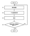
- 1 is a flowchart showing an example of a method for measuring and adjusting a diffraction grating tilt according to an embodiment of the present disclosure.
- 1 is a flowchart showing an example of an analysis process in a calculation unit according to an embodiment of the present disclosure.
- 1 is a flowchart showing an example of additional analysis processing in a calculation unit when measuring the tilt of parallel light.
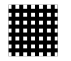
- FIG. 1 is a schematic diagram illustrating an example of an image captured by an imaging unit according to an embodiment of the present disclosure.
- FIG. 1 is a schematic diagram illustrating an example of an analysis process in a calculation unit according to an embodiment of the present disclosure
- the assembly of the wavefront analysis device described in Patent Document 1 has the problem that if an error occurs in the tilt between the diffraction grating and the imaging unit, the error is also added to the wavefront that is the analysis result. Therefore, it is necessary to perform assembly while suppressing this tilt error.
- the present disclosure aims to provide a method for measuring and adjusting the tilt of a diffraction grating, which measures and adjusts with high precision the tilt between a diffraction grating and an imaging unit that constitutes a wavefront analyzer.
- Fig. 1A is a diagram for explaining the configuration of a diffraction grating tilt adjustment device 100 capable of implementing a method for measuring and adjusting the tilt of a diffraction grating according to an embodiment of the present disclosure.
- Fig. 1B is a diagram for explaining the configuration of a wavefront analyzer 101 of the diffraction grating tilt adjustment device 100 according to an embodiment of the present disclosure, and the measurement and adjustment of the diffraction grating tilt.
- the diffraction grating tilt adjustment device 100 includes a wavefront analyzer 101, a light projection unit 104, and a calculation unit 105.
- the wavefront analyzer 101 is composed of a diffraction grating 102 and an imaging unit 103, for example an image sensor, and analyzes the distortion of the interference image that occurs behind the diffraction grating when light is irradiated, to restore the wavefront.
- the light projection unit 104 and the calculation unit 105 are used to measure and adjust the tilt of the diffraction grating 102.
- the light projecting unit 104 irradiates the diffraction grating 102 with light 106.
- the diffraction grating 102 splits light using the phenomenon of diffraction, transmitting light 106 and converting it into diffracted light, which is then projected onto the imaging unit 103.
- the imaging unit 103 captures and acquires the diffracted light from the diffraction grating 102 as image data.
- the calculation unit 105 performs frequency analysis on the image data from the imaging unit 103 to calculate a numerical index corresponding to the amount of tilt of the diffraction grating 102.
- a pseudo point light source obtained by combining a pinhole with a coherent light source such as a laser or an incoherent light source such as an LED lamp can be used as the light projecting unit 104.
- a coherent light source such as a laser or an incoherent light source such as an LED lamp
- interference fringes are generated due to interference between the diffracted lights.
- the contrast of the interference fringes is improved, which is expected to be advantageous in quantifying the tilt of the diffraction grating 102.
- parallel light i.e., collimated light
- the position of the diffraction peak which will be described later, depends on the wavefront aberration of the light 106, the angle of incidence, the number of vertical and horizontal pixels of the image data acquired by the imaging unit 103, the in-plane rotation angle of the grating pattern of the diffraction grating 102, the pitch of the grating pattern of the diffraction grating 102, the pixel pitch of the imaging unit 103, or the tilt of the diffraction grating 102 with respect to the imaging unit 103, but by using collimated light, the effect of the wavefront aberration of the light 106 can be eliminated, making it easier to detect the diffraction peak.
- the tilt of diffraction grating 102 relative to imaging unit 103 can be measured and adjusted with an accuracy of 0 ⁇ 0.05 degrees to 0 ⁇ 0.001 degrees.
- the larger the incidence angle ⁇ the higher the tilt measurement sensitivity and adjustment accuracy.
- the incidence angle ⁇ is less than 3 degrees, the tilt of diffraction grating 102 relative to imaging unit 103 cannot be measured with an accuracy of 0 ⁇ 0.05 degrees or more due to an error in the numerical index caused by fluctuations in the brightness of the interference fringes.
- the tilt of diffraction grating 102 relative to imaging unit 103 cannot be measured with an accuracy of 0 ⁇ 0.05 degrees or more due to dimensional errors in the fixing members of diffraction grating 102 or imaging unit 103 or errors in the amount of tilt due to thermal expansion, etc.
- the diffraction grating 102 converts the light 106 from the light projecting unit 104 into diffracted light, and projects the diffracted light onto the imaging unit 103 .
- the diffraction grating 102 may be a one- or two-dimensional amplitude grating, a phase grating or a combination of amplitude and phase gratings, or a Hartmann mask or modified Hartmann mask (MHM) as described under reference GR in French patent application FR 2 795 175 A1.
- the imaging unit 103 is composed of an image sensor having a plurality of pixels, receives the diffracted light from the diffraction grating 102, and detects it as image data.
- the image data is analyzed by the calculation unit 105, so that the amount of tilt of the diffraction grating 102 can be quantified.
- the imaging unit 103 may be a CMOS camera or a CCD camera.
- the imaging unit 103 is fixed to one surface of an imaging unit holding base 123, which is, for example, a rectangular parallelepiped, and the rectangular plate-shaped diffraction grating 102 is placed on top of it so that they overlap with a gap between them, and the four corners of the diffraction grating 102 are adjustably attached to the imaging unit holding base 123 with screws 122. Therefore, by turning each screw 122 forwards or backwards to tighten or loosen it, the amount of tilt of the diffraction grating 102 relative to the imaging unit 103 can be adjusted.
- an imaging unit holding base 123 which is, for example, a rectangular parallelepiped
- the rectangular plate-shaped diffraction grating 102 is placed on top of it so that they overlap with a gap between them, and the four corners of the diffraction grating 102 are adjustably attached to the imaging unit holding base 123 with screws 122. Therefore, by turning each screw 122 forwards or backwards to tighten or loosen it,
- the calculation unit 105 receives image data from the imaging unit 103, and by analyzing the received image data, calculates a numerical index corresponding to the amount of tilt of the diffraction grating 102. That is, the calculation unit 105 acquires image data from the imaging unit 103, and calculates a numerical index corresponding to the amount of tilt of the diffraction grating 102 by frequency-analyzing the luminance distribution of the acquired image data.
- FIG. 2A is a flow chart illustrating an example method for measuring and adjusting a grating tilt according to an embodiment of the present disclosure.
- An example of a method for measuring and adjusting the diffraction grating tilt in the embodiment is as follows.
- step S1 the screw 122 is turned to adjust the inclination of the diffraction grating 102 relative to the imaging unit 103.
- this step may be omitted and the process may begin with step S2.
- step S2 light 106 is irradiated from the light projecting unit 104 onto the diffraction grating 102, and the diffracted light that passes through the diffraction grating 102 is captured as image data by the imaging unit 103, and an interference image is obtained by the imaging unit 103.
- step S3 the calculation unit 105 performs a calculation process on the image data acquired by the imaging unit 103, and the calculation unit 105 calculates a numerical index corresponding to the amount of tilt of the diffraction grating 102 relative to the imaging unit 103.
- step S4 the calculation unit 105 compares whether the calculated numerical index matches a target value, which is the theoretical value of the numerical index when the diffraction grating 102 and the imaging unit 103 are parallel. If they match, the measurement method and adjustment method are terminated. If they do not match, the process returns to step S1, and the tilt of the diffraction grating 102 relative to the imaging unit 103 is adjusted so that the numerical index matches the target value.
- steps S2 to S3 are the measurement method
- steps S1 to S4 are the adjustment method.
- FIG. 2B is a flowchart showing an example of analysis processing in the calculation unit 105 during tilt measurement and adjustment.
- FIG. 2C is a flowchart showing an example of analysis processing in the calculation unit 105 during tilt measurement of parallel light.
- FIG. 3 is a schematic diagram showing an example of an interference image obtained by the imaging unit 103 when an MHM is used as the diffraction grating 102.
- FIG. 4 is a schematic diagram showing a Fourier transform image obtained by performing a two-dimensional Fourier transform on the interference image in FIG. 3.
- window processing is performed on the image data to reduce the effect of noise on the peak extraction in step S33.
- a window processing function a Hanning window or the like is used.
- step S32 the Fourier transform of the image data windowed in step S31 is calculated to obtain a Fourier transform image.
- step S33 the positions of the diffraction peaks are detected in the Fourier transform image calculated in step S32.
- the positions of these peaks depend on the wavefront aberration of the light 106, the angle of incidence, the number of vertical and horizontal pixels of the image data acquired by the imaging unit 103, the in-plane rotation angle of the grating pattern of the diffraction grating 102, the pitch of the grating pattern of the diffraction grating 102, the pixel pitch of the imaging unit 103, or the tilt of the diffraction grating 102 and the imaging unit 103.
- an MHM is used as the diffraction grating 102
- the positions of the four first-order diffraction peaks 107 in FIG. 4 are extracted.
- a numerical index corresponding to the amount of tilt of the diffraction grating 102 with respect to the imaging unit 103 is calculated from the position of the diffraction peak 107 extracted in step S33.
- a numerical index calculated from the sum or difference of the distances of the diffraction peak positions can be used. If the distances between points A and B, between points B and C, between points AC and BD of the first-order diffraction peak 107 in Fig. 4 are dAB , dBC , dAC, and dBD , respectively, the numerical indexes I and J can be calculated by taking the sum or difference of these as follows:
- step S35 the irradiation angle of the light-projecting unit 104 relative to the diffraction grating 102 is changed to change the incident angle ⁇ of the light 106 from the light-projecting unit 104 relative to the diffraction grating 102.
- step S36 the calculation unit 105 calculates the difference between the numerical indices before and after the change in the incident angle.
- step S37 the difference value is regarded as a numerical index that quantifies the tilt of the diffraction grating 102, thereby reducing the influence of errors in the pitch of the grating pattern of the diffraction grating 102 and the pixel pitch of the imaging unit 103 on the numerical index, and the tilt of the diffraction grating 102 relative to the imaging unit 103 can be measured.
- step S4 the calculation unit 105 compares whether the numerical index calculated in step S34 or S37 matches the target value. If the calculation unit 105 determines that the calculated numerical index matches the target value, the measurement method and the adjustment method are terminated. If the calculation unit 105 determines that the calculated numerical index does not match the target value, the process returns to step S1, and the screw 122 is turned to adjust the tilt of the diffraction grating 102 relative to the imaging unit 103 so that the numerical index matches the target value.
- the relationship between the numerical index and the tilt angle is obtained by experiment or simulation, and the amount of change in the tilt angle per rotation of the screw 122 is calculated from the pitch of the screw 122 and the spacing between the screws, it is possible to determine how much the screw 122 should be rotated from the numerical index.
- the calculation unit 105 calculates the theoretical value of the numerical index when the diffraction grating 102 and the imaging unit 103 are parallel, and stores the theoretical value as the target value in the calculation unit 105.
- the theoretical value of the numerical index can be calculated based on optical simulation.
- the theoretical value can be calculated from the number of vertical and horizontal pixels of the image data acquired by the imaging unit 103, the in-plane rotation angle of the grating pattern of the diffraction grating 102, the pitch of the grating pattern of the diffraction grating 102, and the pixel pitch of the imaging unit 103.
- the pixel pitch of the imaging unit 103 is uniform, and the light 106 is parallel, the target values of the numerical indexes I and J described above are 0, so the tilt of the diffraction grating 102 with respect to the imaging unit 103 is adjusted so that the values of I and J are 0.
- light 106 is irradiated onto the diffraction grating 102 from the light projecting unit 104, the diffracted light is captured as image data by the imaging unit 103, the calculation unit 105 acquires the image data from the imaging unit 103, and the calculation unit 105 calculates a numerical index corresponding to the amount of tilt of the diffraction grating 102 based on this image data.
- the amount of tilt of the diffraction grating 102 relative to the imaging unit 103 can be measured and adjusted.
- the amount of tilt adjustment of the diffraction grating 102 can be measured and adjusted easily and with high accuracy. This has the great effect of improving the performance of the wavefront analysis device 101.
- a method for measuring a tilt of a diffraction grating with respect to an imaging unit of a wavefront analyzer including a diffraction grating that divides light by a diffraction phenomenon and an imaging unit that images light transmitted through the diffraction grating comprising: Irradiating the diffraction grating with light from a light projection unit for irradiating light; The diffracted light transmitted through the diffraction grating is captured as image data by the imaging unit; A calculation unit performs a Fourier transform on the image data from the imaging unit to generate a Fourier transform image; a numerical index corresponding to an amount of tilt of the diffraction grating with respect to the imaging unit is calculated by the calculation unit from a position of a diffraction peak in the Fourier transform image; How to measure the tilt of a diffraction grating.
- the diffraction grating is irradiated with light from the light projection unit, the diffracted light from the diffraction grating is acquired as image data by the imaging unit, and a numerical index corresponding to the amount of tilt of the diffraction grating is calculated from the image data, thereby making it possible to easily and highly accurately measure the tilt of the diffraction grating that constitutes the wavefront analysis device.
- the numerical index is adjusted so that it coincides with a target value, which is the theoretical value of the numerical index when the diffraction grating and the imaging unit are parallel, the tilt of the diffraction grating relative to the imaging unit can be easily and accurately adjusted.
- the tilt of the diffraction grating constituting the wavefront analyzer can be measured easily and with high accuracy by irradiating the diffraction grating with light from the light projection unit, acquiring the diffracted light from the diffraction grating as image data in the imaging unit, and calculating a numerical index corresponding to the amount of tilt of the diffraction grating from the image data.
- the tilt of the diffraction grating relative to the imaging unit can be easily and accurately adjusted.
- the method for measuring and adjusting the tilt of a diffraction grating can measure and adjust the tilt amount of a diffraction grating with high accuracy by irradiating light from a light projecting unit onto the diffraction grating, converting it into diffracted light by the diffraction grating, acquiring the diffracted light as image data by an imaging unit, and calculating a numerical index corresponding to the tilt amount of the diffraction grating based on the luminance distribution of the pixels that make up the image data. Therefore, by using this measurement method and adjustment method in the assembly of a wavefront analysis device, it is possible to suppress wavefront measurement errors due to the tilt of the diffraction grating and improve the accuracy of wavefront measurement and adjustment.
- Wavefront analysis device 102
- Diffraction grating 103
- Image capture unit 104
- Light projection unit 105
- Calculation unit 106
Landscapes
- Physics & Mathematics (AREA)
- General Physics & Mathematics (AREA)
- Spectroscopy & Molecular Physics (AREA)
- Testing Of Optical Devices Or Fibers (AREA)
Priority Applications (1)
| Application Number | Priority Date | Filing Date | Title |
|---|---|---|---|
| JP2025527554A JPWO2024257517A1 (enExample) | 2023-06-12 | 2024-05-10 |
Applications Claiming Priority (2)
| Application Number | Priority Date | Filing Date | Title |
|---|---|---|---|
| JP2023096285 | 2023-06-12 | ||
| JP2023-096285 | 2023-06-12 |
Publications (1)
| Publication Number | Publication Date |
|---|---|
| WO2024257517A1 true WO2024257517A1 (ja) | 2024-12-19 |
Family
ID=93852025
Family Applications (1)
| Application Number | Title | Priority Date | Filing Date |
|---|---|---|---|
| PCT/JP2024/017351 Ceased WO2024257517A1 (ja) | 2023-06-12 | 2024-05-10 | 回折格子のチルトの測定方法及び調整方法 |
Country Status (2)
| Country | Link |
|---|---|
| JP (1) | JPWO2024257517A1 (enExample) |
| WO (1) | WO2024257517A1 (enExample) |
Citations (6)
| Publication number | Priority date | Publication date | Assignee | Title |
|---|---|---|---|---|
| JP2009244156A (ja) * | 2008-03-31 | 2009-10-22 | Nikon Corp | 分光装置、及び分光共焦点顕微鏡 |
| JP2011257360A (ja) * | 2010-06-11 | 2011-12-22 | Canon Inc | トールボット干渉計およびその調整方法 |
| JP2014228490A (ja) * | 2013-05-24 | 2014-12-08 | 太陽誘電株式会社 | 変位計測装置及び変位計測方法 |
| WO2017138411A1 (ja) * | 2016-02-08 | 2017-08-17 | コニカミノルタ株式会社 | 形状測定方法、形状測定装置、検出方法および検出装置 |
| JP2018009856A (ja) * | 2016-07-13 | 2018-01-18 | キヤノン株式会社 | 波面計測方法、波面計測装置、プログラムおよび記録媒体 |
| JP2019533174A (ja) * | 2016-09-30 | 2019-11-14 | ファシックPhasics | 高精細度で電磁波を解析するための方法および装置 |
-
2024
- 2024-05-10 JP JP2025527554A patent/JPWO2024257517A1/ja active Pending
- 2024-05-10 WO PCT/JP2024/017351 patent/WO2024257517A1/ja not_active Ceased
Patent Citations (6)
| Publication number | Priority date | Publication date | Assignee | Title |
|---|---|---|---|---|
| JP2009244156A (ja) * | 2008-03-31 | 2009-10-22 | Nikon Corp | 分光装置、及び分光共焦点顕微鏡 |
| JP2011257360A (ja) * | 2010-06-11 | 2011-12-22 | Canon Inc | トールボット干渉計およびその調整方法 |
| JP2014228490A (ja) * | 2013-05-24 | 2014-12-08 | 太陽誘電株式会社 | 変位計測装置及び変位計測方法 |
| WO2017138411A1 (ja) * | 2016-02-08 | 2017-08-17 | コニカミノルタ株式会社 | 形状測定方法、形状測定装置、検出方法および検出装置 |
| JP2018009856A (ja) * | 2016-07-13 | 2018-01-18 | キヤノン株式会社 | 波面計測方法、波面計測装置、プログラムおよび記録媒体 |
| JP2019533174A (ja) * | 2016-09-30 | 2019-11-14 | ファシックPhasics | 高精細度で電磁波を解析するための方法および装置 |
Also Published As
| Publication number | Publication date |
|---|---|
| JPWO2024257517A1 (enExample) | 2024-12-19 |
Similar Documents
| Publication | Publication Date | Title |
|---|---|---|
| KR102549058B1 (ko) | 광학 측정 장치 및 광학 측정 방법 | |
| US10288408B2 (en) | Scanning white-light interferometry system for characterization of patterned semiconductor features | |
| US10928187B2 (en) | Compensation for Goos-Hanchen error in autofocus systems | |
| US20100201811A1 (en) | Depth ranging with moire patterns | |
| JP5743419B2 (ja) | 形状測定方法及び装置並びに歪み測定方法及び装置 | |
| WO2011083544A1 (ja) | 干渉を用いた膜厚計測装置及び干渉を用いた膜厚計測方法 | |
| CN110186388B (zh) | 基于白光干涉光谱的同步相移测量系统与方法 | |
| JPWO2022138716A5 (enExample) | ||
| WO2019236084A1 (en) | Overlay measurement using phase and amplitude modeling | |
| JPWO2023042339A5 (enExample) | ||
| WO2023042339A1 (ja) | 光学測定システムおよび光学測定方法 | |
| JP2023138922A (ja) | 回折型オーバーレイ用複素光位相測定装置 | |
| CN121141699A (zh) | 一种光学元件表面图案的结构光测试系统 | |
| JP2538435B2 (ja) | 縞位相分布解析方法および縞位相分布解析装置 | |
| CN111649693B (zh) | 一种样品形貌测量装置及方法 | |
| TW202548430A (zh) | 使用多波長確定掃描目標之疊對量測之系統及方法 | |
| CN115185161A (zh) | 一种调焦调平测量方法及测量系统 | |
| KR101436403B1 (ko) | 정현파 격자를 이용한 섀도우모아레 방법 및 이를 이용한 측정 장치 | |
| JP2013257206A (ja) | 3次元計測装置でのプロジェクタの調整方法と調整装置 | |
| WO2005001774A2 (en) | Methods and apparatus for reducing error in interferometric imaging measurements | |
| JP2009025259A (ja) | 縞画像解析方法、干渉計装置、およびパターン投影形状測定装置 | |
| JP7080718B2 (ja) | 光学装置及び形状測定方法 | |
| CN120043738B (zh) | 一种信号校正方法、光学检测设备和存储介质 | |
| JP2018009856A (ja) | 波面計測方法、波面計測装置、プログラムおよび記録媒体 | |
| US12373936B2 (en) | System and method for overlay metrology using a phase mask |
Legal Events
| Date | Code | Title | Description |
|---|---|---|---|
| 121 | Ep: the epo has been informed by wipo that ep was designated in this application |
Ref document number: 24823139 Country of ref document: EP Kind code of ref document: A1 |
|
| ENP | Entry into the national phase |
Ref document number: 2025527554 Country of ref document: JP Kind code of ref document: A |
|
| NENP | Non-entry into the national phase |
Ref country code: DE |
|
| 122 | Ep: pct application non-entry in european phase |
Ref document number: 24823139 Country of ref document: EP Kind code of ref document: A1 |