WO2024257515A1 - 二次電池用通電部品 - Google Patents
二次電池用通電部品 Download PDFInfo
- Publication number
- WO2024257515A1 WO2024257515A1 PCT/JP2024/017328 JP2024017328W WO2024257515A1 WO 2024257515 A1 WO2024257515 A1 WO 2024257515A1 JP 2024017328 W JP2024017328 W JP 2024017328W WO 2024257515 A1 WO2024257515 A1 WO 2024257515A1
- Authority
- WO
- WIPO (PCT)
- Prior art keywords
- current
- secondary battery
- metal foil
- carrying component
- foil material
- Prior art date
- Legal status (The legal status is an assumption and is not a legal conclusion. Google has not performed a legal analysis and makes no representation as to the accuracy of the status listed.)
- Ceased
Links
Images



Classifications
-
- H—ELECTRICITY
- H01—ELECTRIC ELEMENTS
- H01M—PROCESSES OR MEANS, e.g. BATTERIES, FOR THE DIRECT CONVERSION OF CHEMICAL ENERGY INTO ELECTRICAL ENERGY
- H01M50/00—Constructional details or processes of manufacture of the non-active parts of electrochemical cells other than fuel cells, e.g. hybrid cells
- H01M50/50—Current conducting connections for cells or batteries
- H01M50/502—Interconnectors for connecting terminals of adjacent batteries; Interconnectors for connecting cells outside a battery casing
- H01M50/503—Interconnectors for connecting terminals of adjacent batteries; Interconnectors for connecting cells outside a battery casing characterised by the shape of the interconnectors
-
- H—ELECTRICITY
- H01—ELECTRIC ELEMENTS
- H01M—PROCESSES OR MEANS, e.g. BATTERIES, FOR THE DIRECT CONVERSION OF CHEMICAL ENERGY INTO ELECTRICAL ENERGY
- H01M50/00—Constructional details or processes of manufacture of the non-active parts of electrochemical cells other than fuel cells, e.g. hybrid cells
- H01M50/50—Current conducting connections for cells or batteries
- H01M50/502—Interconnectors for connecting terminals of adjacent batteries; Interconnectors for connecting cells outside a battery casing
- H01M50/521—Interconnectors for connecting terminals of adjacent batteries; Interconnectors for connecting cells outside a battery casing characterised by the material
- H01M50/522—Inorganic material
-
- H—ELECTRICITY
- H01—ELECTRIC ELEMENTS
- H01M—PROCESSES OR MEANS, e.g. BATTERIES, FOR THE DIRECT CONVERSION OF CHEMICAL ENERGY INTO ELECTRICAL ENERGY
- H01M50/00—Constructional details or processes of manufacture of the non-active parts of electrochemical cells other than fuel cells, e.g. hybrid cells
- H01M50/50—Current conducting connections for cells or batteries
- H01M50/502—Interconnectors for connecting terminals of adjacent batteries; Interconnectors for connecting cells outside a battery casing
- H01M50/521—Interconnectors for connecting terminals of adjacent batteries; Interconnectors for connecting cells outside a battery casing characterised by the material
- H01M50/526—Interconnectors for connecting terminals of adjacent batteries; Interconnectors for connecting cells outside a battery casing characterised by the material having a layered structure
-
- Y—GENERAL TAGGING OF NEW TECHNOLOGICAL DEVELOPMENTS; GENERAL TAGGING OF CROSS-SECTIONAL TECHNOLOGIES SPANNING OVER SEVERAL SECTIONS OF THE IPC; TECHNICAL SUBJECTS COVERED BY FORMER USPC CROSS-REFERENCE ART COLLECTIONS [XRACs] AND DIGESTS
- Y02—TECHNOLOGIES OR APPLICATIONS FOR MITIGATION OR ADAPTATION AGAINST CLIMATE CHANGE
- Y02E—REDUCTION OF GREENHOUSE GAS [GHG] EMISSIONS, RELATED TO ENERGY GENERATION, TRANSMISSION OR DISTRIBUTION
- Y02E60/00—Enabling technologies; Technologies with a potential or indirect contribution to GHG emissions mitigation
- Y02E60/10—Energy storage using batteries
Definitions
- the present invention relates to current-carrying components for secondary batteries that are primarily installed in automobiles, etc.
- bolt holes through holes
- current-carrying components formed by laminating multiple layers of metal foil material to fasten these parts to other components, and it is necessary to improve the contact between the metal foil materials in order to reduce resistance when electricity is passed through them.
- the components need to be rigid enough to withstand the tightening load applied when fastened using bolts.
- the present invention aims to provide a secondary battery current-carrying component made of metal foil material with bolt holes (through holes) that can ensure the rigidity of the bolt holes while also ensuring the smoothness required for bolt parts.
- the current-carrying component for a secondary battery of the present invention is formed by stacking multiple sheets of metal foil material in the thickness direction, and the current-carrying component for a secondary battery has two or more through holes in the thickness direction of the multiple sheets of metal foil material, and the inner surface of the through hole has a joint where the multiple sheets of metal foil material are solid-phase-bonded to each other, and a step is provided on one end side of the joint.
- the material of the metal foil material may be any of aluminum, aluminum alloy, copper, and copper alloy.
- the current-carrying component for a secondary battery of the present invention is composed of multiple metal foil materials and has two or more through holes in its thickness direction, and the inner surfaces of the through holes have joints where the multiple metal foil materials are solid-phase welded together, and a step is provided on one end side of the joint. Therefore, the contact between the metal foils is high, and while maintaining rigidity, the current-carrying component is ensured, and installation locations for fixing components such as bolts can be secured, so that the component can fully adapt to the fastening load with other components using bolts, etc.
- FIG. 1 is a schematic cross-sectional view of a current-carrying component 100 for a secondary battery according to a first embodiment of the present invention
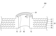
- 1 is a schematic cross-sectional view of a current-carrying component 200 for a secondary battery according to a second embodiment of the present invention
- 1 is a schematic cross-sectional view of a current-carrying component 300 for a secondary battery according to a third embodiment of the present invention.
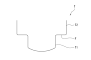
- FIG. 1 is an overall view of a friction stir welding tool T used in manufacturing a current-carrying component for a secondary battery according to the present invention.
- FIG. 5 is an enlarged view of part A shown in FIG.
- FIG. 1 shows a schematic cross-sectional view of one through hole H1 in the current-carrying part for secondary batteries 100 according to the first embodiment of the present invention
- FIG. 2 shows a schematic cross-sectional view of one through hole H2 in the current-carrying part for secondary batteries 200 according to the second embodiment
- FIG. 3 shows a schematic cross-sectional view of one through hole H3 in the current-carrying part for secondary batteries 300 according to the third embodiment.
- FIG. 4 shows an overall view of the friction stir welding tool T used in manufacturing the current-carrying parts for secondary batteries 200, 300 according to the second and third embodiments of the present invention shown in FIG. 2 and FIG. 3, and
- FIG. 5 shows an enlarged view of the tip portion (part A in FIG. 4) of the friction stir welding tool T.
- the current-carrying component for a secondary battery (first embodiment) 100 of the present invention is provided with an annular protrusion 16 that protrudes in the thickness direction of the metal foil material 10 on one end side of the joint Y1, i.e., on the side of the metal foil material 11 in the outermost layer.
- annular protrusion 16 By providing this annular protrusion 16, a step d1 is formed between the metal foil material 11 in the outermost layer.
- the outermost surface 16F of the protrusion 16 is a flat surface, and when the current-carrying component for a secondary battery (first embodiment) 100 of this embodiment is fixed to another component using a bolt or the like, components such as a bolt, nut, and washer can be stably installed.
- the inner peripheral surface of the protrusion 16 and the inner peripheral surface of the through hole H1 are continuously connected to each other, that is, the inner peripheral surface of the protrusion 16 and the inner peripheral surface of the through hole H1 form a single, substantially cylindrical inner peripheral surface.
- the current-carrying component for a secondary battery (second embodiment) 200 of the present invention is formed in a form in which a plurality of metal foil materials 20 (21, 22, 23, 24, 25) are stacked in the thickness direction as shown in Figure 2, similar to the first embodiment described above.
- This current-carrying component for a secondary battery 200 also has a through hole H2 as shown in Figure 2, and the inner surface of the through hole H2 is formed as a joint Y2 in which five sheets of metal foil materials 21, 22, 23, 24, 25 are solid-phase-bonded (integrated structurally and morphologically) in this embodiment as well.
- the current-carrying component for a secondary battery (second embodiment) 200 of the present invention is provided with an annular protrusion 26 on one end side of the joint Y2, i.e., on the side of the metal foil material 21 in the outermost layer, in the same manner as in the first embodiment described above.
- an annular protrusion 26 is formed between the metal foil material 21 in the outermost layer.
- the annular protrusion 26 of the current-carrying component for a secondary battery (second embodiment) 200 of this embodiment is further provided with a step d2 on the inside (the inner surface side of the through hole H2) as shown in FIG. 2.
- a part of the inner peripheral surface of the protrusion 26 and the inner peripheral surface of the through hole H2 form a continuous inner peripheral surface. That is, a part of the inner peripheral surface of the protrusion 26 and the inner peripheral surface of the through hole H2 form a single, substantially cylindrical inner peripheral surface.
- the inner peripheral surface of the protrusion 26 is formed so as to protrude from the surface of the metal foil material 20. That is, the step d2 on the inner peripheral surface side of the annular protrusion 26 is smaller in dimension than the step on the outer peripheral surface side of the annular protrusion 26.
- a flat surface 27 is formed.
- parts such as bolts, nuts, and washers can be stably installed on this flat surface 27.
- a flange portion is formed on the outside (outer periphery) of this flat surface 27, which makes it easy to position parts such as bolts, nuts, and washers.
- the flat surface 27 of the current-carrying component 200 for a secondary battery shown in FIG. 2 can be formed using the tip portion of the friction stir welding tool T shown in FIG. 4, i.e., the flat portion F corresponding to the connection portion between the small diameter portion T1 and the large diameter portion T2 of the tip of the friction stir welding tool T.
- the current-carrying component for a secondary battery (third embodiment) 300 of the present invention is formed in a form in which a plurality of metal foil materials 30 (31, 32, 33, 34, 35) are stacked in the thickness direction as shown in Figure 3, as in the case of the first embodiment described above.
- This current-carrying component for a secondary battery 300 also has a through hole H3 as shown in Figure 3, and the inner surface of the through hole H3 is formed as a joint Y3 in which five sheets of metal foil materials 31, 32, 33, 34, 35 are solid-phase-bonded (organically and morphologically integrated) in this embodiment as well.
- the current-carrying component for a secondary battery (third embodiment) 300 of the present invention has an annular convex portion 36 on one end side of the joint Y3, i.e., on the side of the metal foil material 31 in the outermost layer, as in the first and second embodiments described above.
- annular convex portion 36 By providing this annular convex portion 36, a step is formed between the metal foil material 31 in the outermost layer, so that a flat surface is also formed on the outermost surface of the annular convex portion 36, allowing parts such as bolts, nuts, and washers to be stably installed.
- a step d3 of the through hole H3 is further provided on the inside of the convex portion 36 of the current-carrying component for a secondary battery (third embodiment) 300 of this embodiment, as shown in FIG. 3.
- a step d3 is also provided on the inside of the protrusion 36 (the inner side of the through hole H3), forming a flat surface 37. That is, when the current-carrying component for a secondary battery (third embodiment) 300 of this embodiment is fixed to another component using a bolt or the like, components such as bolts, nuts, and washers can be stably installed on this flat surface 37.
- a flange portion (not shown) is formed on the outside (outer periphery) of this flat surface 37, and as a result, the positioning of components such as bolts, nuts, and washers can be easily performed.
- the surface of the flat surface 37 is recessed from the surface of the metal foil material 30. That is, the step d3 on the inner circumferential surface side of the annular protrusion 36 is larger than the step on the outer circumferential surface side of the annular protrusion 36.
- the flat surface 37 of the current-carrying component 300 for a secondary battery shown in FIG. 3 can be formed using the tip portion of the friction stir welding tool T shown in FIG. 4, i.e., the flat portion F corresponding to the connection portion between the small diameter portion T1 and the large diameter portion T2 of the tip of the friction stir welding tool T.
- the thickness of each sheet may be 0.2 mm or less (JIS H4160, H4170). If the metallic foil material is made of copper or a copper alloy, the thickness of each sheet may be 0.21 mm or less (JIS C6515).
Landscapes
- Chemical & Material Sciences (AREA)
- Chemical Kinetics & Catalysis (AREA)
- Electrochemistry (AREA)
- General Chemical & Material Sciences (AREA)
- Inorganic Chemistry (AREA)
- Connection Of Batteries Or Terminals (AREA)
Abstract
本発明の二次電池用通電部品100は、複数枚の金属製箔材11~15が厚み方向に積層されることで形成されるものであり、当該二次電池用通電部品には複数枚の金属製箔材11~15の厚み方向に二以上の貫通穴H1を備えている。また、貫通穴H1の内周面には複数枚の金属製箔材11~15が固相接合された接合部Y1を有して、当該接合部Y1の一端側に段差d1を設ける。さらに、当該二次電池用通電部品100に金属製箔材を5枚以上使用して、1枚当たりの厚さを0.21mm以下にすることもできる。
Description
本発明は、主に自動車等に搭載される二次電池用途の通電部品に関する。
2枚以上の板材や箔材同士から形成される通電部品、特に自動車等の二次電池用途の通電部品は、バスバとも呼ばれており、アルミニウム合金や銅合金など高導電性の材料から形成されている。技術が開示されている(特許文献1参照)。
しかしながら、金属製の箔材を多数積層させて形成する通電部品にボルト穴(貫通穴)を設けて、その部分を他の部品と締結する場合があり、通電時の抵抗を低減するために金属製の箔材同士の接触性を高める必要がある。つまり、ボルトを用いた締結時にその締め付け荷重にかかる荷重を耐え得るだけの剛性が求められる。
例えば、多数の金属製の箔材同士を圧着で接合する場合には、金属箔同士の接触性が低いので、箔材同士に歪みが生じて、前述の締め付け荷重に順応できないという問題がある。また、多数の金属製の箔材同士をレーザ溶接で接合する場合には、接合時に金属箔同士で位置ずれが生じると溶接作業が困難になり、接合面の平滑性が確保できないという問題があった。
そこで、本発明はボルト穴(貫通穴)を有した金属製箔材の二次電池用通電部品においても、ボルト穴の剛性を確保しつつ、ボルト部品に必要な平滑性を確保できる二次電池用通電部品を提供することを課題とする。
本発明の二次電池用通電部品は、複数枚の金属製箔材が厚み方向に積層されることで形成される二次電池用通電部品において、当該二次電池用通電部品に複数の金属製箔材の厚み方向に二以上の貫通穴を設けて、当該貫通穴の内周面に複数枚の金属製箔材が互いに固相接合された接合部を備えて、当該接合部の一端側に段差を設ける。
また、金属製箔材を5枚以上として、1枚当たりの厚さを0.21mm以下とすることもできる。この場合、金属製箔材の材質は、アルミニウム,アルミニウム合金,銅,銅合金のうちのいずれかとしても構わない。
本発明の二次電池用通電部品は、複数の金属製箔材から構成されて、その厚み方向に二以上の貫通穴を備えており、それらの貫通穴の内周面は複数の金属製箔材が互いに固相接合された接合部を有して、かつその接合部の一端側に段差を設けている。そのため、金属箔同士の接触性が高く、剛性を保ちながら、通電部品としての通電性を確保しつつ、かつボルトなどの固定部品の設置箇所も確保できるので、ボルトなどを使用した他部品との締結荷重にも十分順応できるという効果を奏する。
本発明の第1ないし第3実施形態である二次電池用通電部品について、図面を用いて説明する。本発明の第1実施形態である二次電池用通電部品100における1つの貫通穴H1の模式断面図を図1、第2実施形態である二次電池用通電部品200における1つの貫通穴H2の模式断面図を図2、第3実施形態である二次電池用通電部品300における1つの貫通穴H3の模式断面図を図3にそれぞれ示す。また、図2および図3に示す本発明の第2および第3実施形態である二次電池用通電部品200,300を製作する際に使用する摩擦かく拌接合工具Tの全体図を図4、摩擦かく拌接合工具Tの先端部分(図4中のA部分)の拡大図を図5にそれぞれ示す。
本発明の二次電池用通電部品(第1実施形態)100は、図1に示す様に複数枚の金属製箔材10(11,12,13,14,15)が厚み方向に積層された形態で形成されている。この二次電池用通電部品100は、図1に示す様に貫通穴H1を有しており、当該貫通穴H1の内周面は、本実施形態の場合、5枚の金属製箔材11,12,13,14,15が互いに固相接合(組織的かつ形態的に一体化)された接合部Y1として形成されている。
また、図1に示す様に本発明の二次電池用通電部品(第1実施形態)100には、当該接合部Y1の一端側、すなわち最表層にある金属製箔材11側には当該金属製箔材10の厚み方向に突出する円環状の凸部16が設けられている。この円環状の凸部16を設けることで、最表層の金属製箔材11の間に段差d1が形成されている。当該凸部16の最表面16Fは平坦面であり、本実施形態の二次電池用通電部品(第1実施形態)100を他の部品とボルトなどを用いて固定する際に、ボルト、ナット、座金などの部品を安定して設置できる。
なお、凸部16の内周面と貫通穴H1の内周面とは連続的に繋がった内周面となっている。すなわち、凸部16の内周面と貫通穴H1の内周面とで一つの略円筒形状の内周面を形成している。
なお、凸部16の内周面と貫通穴H1の内周面とは連続的に繋がった内周面となっている。すなわち、凸部16の内周面と貫通穴H1の内周面とで一つの略円筒形状の内周面を形成している。
次に、本発明の二次電池用通電部品(第2実施形態)200は、前述した第1実施形態の場合と同様に図2に示す様に複数の金属製箔材20(21,22,23,24,25)が厚み方向に積層された形態で形成されている。この二次電池用通電部品200も図2に示す様に貫通穴H2を有しており、当該貫通穴H2の内周面は、本実施形態の場合も5枚の金属製箔材21,22,23,24,25が固相接合(組織的かつ形態的に一体化)された接合部Y2として形成されている。
また、図2に示す様に本発明の二次電池用通電部品(第2実施形態)200には、前述した第1実施形態の場合と同様に当該接合部Y2の一端側、すなわち最表層にある金属製箔材21側に円環状の凸部26が設けられている。この円環状の凸部26を設けることで、最表層の金属製箔材21の間に段差が形成されている。さらに、本実施形態の二次電池用通電部品(第2実施形態)200の円環状の凸部26には、図2に示す様に内側(貫通穴H2の内面側)にも段差d2がさらに設けられている。
なお、凸部26の内周面の一部と貫通穴H2の内周面とは連続的に繋がった内周面となっている。すなわち、凸部26の内周面の一部と貫通穴H2の内周面とで一つの略円筒形状の内周面を形成している 。また、凸部26の内周面は金属製箔材20の表面よりも突出するように形成されている。すなわち、円環状の凸部26の内周面側の段差d2は円環状の凸部26の外周面側の段差よりも小さい寸法となっている。
なお、凸部26の内周面の一部と貫通穴H2の内周面とは連続的に繋がった内周面となっている。すなわち、凸部26の内周面の一部と貫通穴H2の内周面とで一つの略円筒形状の内周面を形成している 。また、凸部26の内周面は金属製箔材20の表面よりも突出するように形成されている。すなわち、円環状の凸部26の内周面側の段差d2は円環状の凸部26の外周面側の段差よりも小さい寸法となっている。
この当該凸部26の内面側にも段差d2を設けることで平坦面27が形成される。つまり、この平坦面27を利用して、本実施形態の二次電池用通電部品(第2実施形態)200を他の部品とボルトなどを用いて固定する際に、この平坦面27にボルト、ナット、座金などの部品を安定して設置できる。また、この平坦面27の外側(外周側)には、鍔部分が形成されることになるので、結果としてボルト、ナット、座金などの部品の位置決めも容易に行うことができる。
なお、図2に示す二次電池用通電部品200平坦面27の形成については、図4に示す摩擦かく拌接合工具Tの先端部分、すなわち摩擦かく拌接合工具T先端の小径部T1と大径部T2の接続部分に相当する平坦部Fを用いて形成することができる。
最後に、本発明の二次電池用通電部品(第3実施形態)300は、前述した第1実施形態の場合と同様に図3に示す様に複数の金属製箔材30(31,32,33,34,35)が厚み方向に積層された形態で形成されている。この二次電池用通電部品300も図3に示す様に貫通穴H3を有しており、当該貫通穴H3の内周面は、本実施形態の場合も5枚の金属製箔材31,32,33,34,35が固相接合(組織的かつ形態的に一体化)された接合部Y3として形成されている。
また、図3に示す様に本発明の二次電池用通電部品(第3実施形態)300には、前述した第1実施形態および第2実施形態の場合と同様に当該接合部Y3の一端側、すなわち最表層にある金属製箔材31側に円環状の凸部36が設けられている。この円環状の凸部36を設けることで、最表層の金属製箔材31の間に段差が形成されているので、円環状の凸部36の最表面には平坦面も形成されて、ボルト、ナット、座金などの部品を安定して設置できる。さらに、第2実施形態の場合と同様に、本実施形態の二次電池用通電部品(第3実施形態)300の凸部36の内側にも、図3に示す様に貫通穴H3の段差d3がさらに設けられている。
この当該凸部36の内側(貫通穴H3の内面側)にも段差d3を設けることで平坦面37が形成される。つまり、この平坦面37を利用して、本実施形態の二次電池用通電部品(第3実施形態)300を他の部品とボルトなどを用いて固定する際に、この平坦面37にボルト、ナット、座金などの部品を安定して設置できる。また、この平坦面37の外側(外周側)には図示しない鍔部分が形成されることになるので、結果としてボルト、ナット、座金などの部品の位置決めも容易に行うことができる。
なお、この実施形態においては、平坦面37の表面は、金属製箔材30の表面よりも凹んだ位置になっている。すなわち、円環状の凸部36の内周面側の段差d3は円環状の凸部36の外周面側の段差よりも大きい寸法となっている。
なお、この実施形態においては、平坦面37の表面は、金属製箔材30の表面よりも凹んだ位置になっている。すなわち、円環状の凸部36の内周面側の段差d3は円環状の凸部36の外周面側の段差よりも大きい寸法となっている。
なお、図3に示す二次電池用通電部品300平坦面37の形成については、図4に示す摩擦かく拌接合工具Tの先端部分、すなわち摩擦かく拌接合工具T先端の小径部T1と大径部T2の接続部分に相当する平坦部Fを用いて形成することができる。
なお、金属製箔材の材質がアルミニウムまたはアルミニウム合金の場合には、1枚当たりの厚さを0.2mm以下にしても構わない(JIS H4160,H4170)。また、金属製箔材の材質が銅または銅合金の場合には、1枚当たりの厚さを0.21mm以下にすることもできる(JIS C6515)。
10,20,30 金属製箔材
11~15 金属製箔材
21~25 金属製箔材
31~35 金属製箔材
100,200,300 二次電池用通電部品
16,26,36 凸部
16F,27,37 平坦面
F 平坦部
H1,H2,H3 貫通穴
T 摩擦かく拌接合工具
T1 小径部
T2 大径部
Y1,Y2,Y3 接合部
d1,d2,d3 段差(寸法)
11~15 金属製箔材
21~25 金属製箔材
31~35 金属製箔材
100,200,300 二次電池用通電部品
16,26,36 凸部
16F,27,37 平坦面
F 平坦部
H1,H2,H3 貫通穴
T 摩擦かく拌接合工具
T1 小径部
T2 大径部
Y1,Y2,Y3 接合部
d1,d2,d3 段差(寸法)
Claims (5)
- 複数枚の金属製箔材が厚み方向に積層されることで形成される二次電池用通電部品であり、前記二次電池用通電部品には前記複数枚の金属製箔材の厚み方向に二以上の貫通穴を備えて、前記貫通穴の内周面には前記複数枚の金属製箔材が互いに固相接合された接合部を有しており、かつ前記接合部の一端側には円環状の凸部が設けられていることを特徴とする二次電池用通電部品。
- 前記円環状の凸部の内側には、段差がさらに設けられていることを特徴とする請求項1に記載の二次電池用通電部品。
- 前記金属製箔材は5枚以上であり、1枚当たりの厚さは0.21mm以下であることを特徴とする請求項1に記載の二次電池用通電部品。
- 前記金属製箔材は5枚以上であり、1枚当たりの厚さは0.21mm以下であることを特徴とする請求項2に記載の二次電池用通電部品。
- 前記金属製箔材は、アルミニウム,アルミニウム合金,銅,銅合金のうちのいずれかの金属製箔材であることを特徴とする請求項1ないし5のいずれか1項に記載の二次電池用通電部品。
Priority Applications (2)
| Application Number | Priority Date | Filing Date | Title |
|---|---|---|---|
| JP2025527552A JPWO2024257515A1 (ja) | 2023-06-13 | 2024-05-10 | |
| US19/418,596 US20260106333A1 (en) | 2023-06-13 | 2025-12-12 | Current-carrying component for secondary battery |
Applications Claiming Priority (2)
| Application Number | Priority Date | Filing Date | Title |
|---|---|---|---|
| JP2023-096673 | 2023-06-13 | ||
| JP2023096673 | 2023-06-13 |
Related Child Applications (1)
| Application Number | Title | Priority Date | Filing Date |
|---|---|---|---|
| US19/418,596 Continuation US20260106333A1 (en) | 2023-06-13 | 2025-12-12 | Current-carrying component for secondary battery |
Publications (1)
| Publication Number | Publication Date |
|---|---|
| WO2024257515A1 true WO2024257515A1 (ja) | 2024-12-19 |
Family
ID=93851815
Family Applications (1)
| Application Number | Title | Priority Date | Filing Date |
|---|---|---|---|
| PCT/JP2024/017328 Ceased WO2024257515A1 (ja) | 2023-06-13 | 2024-05-10 | 二次電池用通電部品 |
Country Status (3)
| Country | Link |
|---|---|
| US (1) | US20260106333A1 (ja) |
| JP (1) | JPWO2024257515A1 (ja) |
| WO (1) | WO2024257515A1 (ja) |
Citations (5)
| Publication number | Priority date | Publication date | Assignee | Title |
|---|---|---|---|---|
| JP2001351438A (ja) * | 2000-06-02 | 2001-12-21 | Hitachi Ltd | フレキシブル導体、その製造方法及び真空スイッチ |
| JP2009199788A (ja) * | 2008-02-20 | 2009-09-03 | Inoue Seisakusho:Kk | 可撓性接続端子 |
| WO2013001644A1 (ja) * | 2011-06-30 | 2013-01-03 | 日立ビークルエナジー株式会社 | 組電池 |
| JP2015225755A (ja) * | 2014-05-27 | 2015-12-14 | 新神戸電機株式会社 | 蓄電デバイスおよびその製造方法 |
| KR20200059691A (ko) * | 2018-11-21 | 2020-05-29 | (주)알씨디에이치 | 내진안전성 확보를 위한 대용량 리튬폴리머 배터리 시스템용 전원모듈간의 전기적 연결구조 |
-
2024
- 2024-05-10 WO PCT/JP2024/017328 patent/WO2024257515A1/ja not_active Ceased
- 2024-05-10 JP JP2025527552A patent/JPWO2024257515A1/ja active Pending
-
2025
- 2025-12-12 US US19/418,596 patent/US20260106333A1/en active Pending
Patent Citations (5)
| Publication number | Priority date | Publication date | Assignee | Title |
|---|---|---|---|---|
| JP2001351438A (ja) * | 2000-06-02 | 2001-12-21 | Hitachi Ltd | フレキシブル導体、その製造方法及び真空スイッチ |
| JP2009199788A (ja) * | 2008-02-20 | 2009-09-03 | Inoue Seisakusho:Kk | 可撓性接続端子 |
| WO2013001644A1 (ja) * | 2011-06-30 | 2013-01-03 | 日立ビークルエナジー株式会社 | 組電池 |
| JP2015225755A (ja) * | 2014-05-27 | 2015-12-14 | 新神戸電機株式会社 | 蓄電デバイスおよびその製造方法 |
| KR20200059691A (ko) * | 2018-11-21 | 2020-05-29 | (주)알씨디에이치 | 내진안전성 확보를 위한 대용량 리튬폴리머 배터리 시스템용 전원모듈간의 전기적 연결구조 |
Also Published As
| Publication number | Publication date |
|---|---|
| JPWO2024257515A1 (ja) | 2024-12-19 |
| US20260106333A1 (en) | 2026-04-16 |
Similar Documents
| Publication | Publication Date | Title |
|---|---|---|
| JP5729429B2 (ja) | 接合構造、及び接合構造の製造方法 | |
| KR101148516B1 (ko) | 트러스트 와셔 및 그 제조방법 | |
| JP2009204159A (ja) | 部品締結構造 | |
| CN105090215A (zh) | 铆螺母单元及其安装方法 | |
| CN107206462A (zh) | 异种材料接合构造以及异种材料接合方法 | |
| WO2024257515A1 (ja) | 二次電池用通電部品 | |
| JP5044162B2 (ja) | 異種金属継手構造及び異種金属接合方法 | |
| JP6620020B2 (ja) | 複合部材 | |
| JP4755887B2 (ja) | 材料の接合方法 | |
| WO2018155090A1 (ja) | 組電池及び組電池用バスバ | |
| CN217153257U (zh) | 一种焊接端板 | |
| JP6176536B2 (ja) | 燃料電池 | |
| US20060286333A1 (en) | Method of and apparatus for weld-bonding workpieces | |
| JP4243113B2 (ja) | シリンダーヘッド用メタルガスケット | |
| JP7132428B1 (ja) | ねじ穴加工方法 | |
| CN223498406U (zh) | 一种提高螺纹长度的紧固件及紧固系统 | |
| JP6985192B2 (ja) | 複合材組立体 | |
| JP3207911B2 (ja) | 金属ベローズの製造方法 | |
| JP2022073683A (ja) | ワッシャ及び締結構造 | |
| JP4758810B2 (ja) | 締付け固定具 | |
| JP2023151953A (ja) | 接合構造、及び自動車の骨格部品 | |
| CN119687089A (zh) | 一种提高螺纹长度的紧固件及紧固系统和操作方法 | |
| US11788612B1 (en) | Torque converter cover to pilot assembly | |
| JP2005233268A (ja) | アルミニウム合金製プロジェクション溶接ナット | |
| US20250377008A1 (en) | Earthing nut and method of manufacturing thereof |
Legal Events
| Date | Code | Title | Description |
|---|---|---|---|
| 121 | Ep: the epo has been informed by wipo that ep was designated in this application |
Ref document number: 24823137 Country of ref document: EP Kind code of ref document: A1 |
|
| ENP | Entry into the national phase |
Ref document number: 2025527552 Country of ref document: JP Kind code of ref document: A |
|
| WWE | Wipo information: entry into national phase |
Ref document number: 2025527552 Country of ref document: JP |
|
| NENP | Non-entry into the national phase |
Ref country code: DE |