WO2024257510A1 - 放射線撮影システム、放射線撮影システムの撮影支援方法及びプログラム - Google Patents
放射線撮影システム、放射線撮影システムの撮影支援方法及びプログラム Download PDFInfo
- Publication number
- WO2024257510A1 WO2024257510A1 PCT/JP2024/017196 JP2024017196W WO2024257510A1 WO 2024257510 A1 WO2024257510 A1 WO 2024257510A1 JP 2024017196 W JP2024017196 W JP 2024017196W WO 2024257510 A1 WO2024257510 A1 WO 2024257510A1
- Authority
- WO
- WIPO (PCT)
- Prior art keywords
- control unit
- imaging
- fpd
- radiation
- information
- Prior art date
- Legal status (The legal status is an assumption and is not a legal conclusion. Google has not performed a legal analysis and makes no representation as to the accuracy of the status listed.)
- Ceased
Links
Images


Classifications
-
- A—HUMAN NECESSITIES
- A61—MEDICAL OR VETERINARY SCIENCE; HYGIENE
- A61B—DIAGNOSIS; SURGERY; IDENTIFICATION
- A61B6/00—Apparatus or devices for radiation diagnosis; Apparatus or devices for radiation diagnosis combined with radiation therapy equipment
Definitions
- the present invention relates to a radiography system, a radiography system imaging support method, and a program.
- Radiation imaging systems have been used that include a radiation irradiation device that generates radiation and a radiation imaging device that receives radiation and generates radiation image data.
- Radiation imaging includes a moving image imaging technique in which a subject is imaged continuously at regular intervals to obtain a plurality of frame images.
- video imaging There are two types of video imaging: “dynamic” imaging, in which the timing of radiation exposure and the timing of generating a radiographic image must be synchronized, and “fluoroscopic” imaging, in which only the timing of the start and end of imaging must be synchronized. For this reason, the radiation imaging systems of Patent Documents 1 and 2 perform a synchronization process for matching the timing of image generation by the radiation imaging device with the irradiation by the radiation irradiation device.
- the console recognizes the synchronization state, but there is no mention of making the synchronization state clear to the imaging technician.
- the imaging device displays on the display unit whether or not the signal is synchronized.
- the display screen is only displayed at a timing when the user is not likely to be looking at the display unit in the workflow during imaging. For this reason, there is room for improvement in calling the attention of imaging technicians.
- the objective of the present invention is to more effectively draw the user's attention by informing them at an appropriate time and in an appropriate manner whether or not the radiographic imaging device is synchronized.
- the radiation imaging system of the present invention comprises: a radiation image capturing device that captures moving images in synchronization with the radiation irradiation device; a presentation unit that presents information regarding a synchronization state of the radiation image capturing device with respect to the radiation irradiation device; A control unit that controls the presentation unit; Equipped with The control unit determines the synchronization status of the radiographic imaging device at at least one of the following times: when the radiographic imaging device is stored in a storage unit, when the radiographic imaging device is removed from the storage unit, when the radiographic imaging device to perform imaging is selected, when the control unit acquires imaging order information from an external device, when imaging order information is added, or when imaging order information is selected by a user, and causes the presentation unit to present information regarding the synchronization status of the radiographic imaging device.
- the imaging support method for the radiation imaging system of the present invention comprises the steps of: 1.
- An imaging support method for a radiation imaging system having a radiation image capturing device that captures a moving image in synchronization with a radiation irradiation device, a presentation unit that presents information regarding a synchronization state of the radiation image capturing device with respect to the radiation irradiation device, and a control unit that controls the presentation unit,
- the synchronization status of the radiographic imaging device is determined at least one of the following times: when the radiographic imaging device is stored in a storage unit, when the radiographic imaging device is removed from the storage unit, when the radiographic imaging device to perform imaging is selected, when the control unit acquires imaging order information from an external device, when imaging order information is added, or when imaging order information is selected by a user, and information regarding the synchronization status of the radiographic imaging device is presented on the presentation unit.
- the program of the present invention comprises: a radiation imaging device that captures moving images in synchronization with a radiation irradiation device, a presentation unit that presents information on a synchronization state of the radiation imaging device with respect to the radiation irradiation device, and a control unit that controls the presentation unit;
- the synchronization status of the radiographic imaging device is determined at least at one of the following times: when the radiographic imaging device is stored in a storage unit, when the radiographic imaging device is removed from the storage unit, when the radiographic imaging device to perform imaging is selected, when the control unit acquires imaging order information from an external device, when imaging order information is added, or when imaging order information is selected by a user, and a function is realized that causes the presentation unit to present information relating to the synchronization status of the radiographic imaging device.
- the present invention makes it possible to properly inform the user of whether or not the radiographic imaging device is synchronized, and to more effectively draw attention to the situation.
- FIG. 1 is a schematic configuration diagram showing a radiation imaging system according to an embodiment of the present invention
- FIG. 2 is a block diagram showing the configuration of a medical cart.
- FIG. 13 is a diagram showing an example of a display screen of examination information displayed on a display unit.
- FIG. 13 is a diagram showing an example of an examination screen of selected examination information.
- FIG. 13 is a diagram showing an examination screen on which radiography order information is added.
- 13 is a flowchart of a synchronization process.
- 13 is a flowchart showing a synchronization state presentation process (1).
- 13 is a display example in which an icon in an image display area of the examination screen is highlighted.
- FIG. 13 is a diagram showing an example of a positive screen.
- FIG. 13 is a diagram showing an example of a negative screen.
- FIG. 13 is a flowchart showing a synchronization state presentation process (2).
- 13 is a flowchart showing a synchronization state presentation process (3).
- FIG. 13 is an explanatory diagram showing a state in which the FPD is stored in a storage section.
- 13 is a flowchart showing a synchronization state presentation process (4).
- FIG. 13 is an explanatory diagram showing a state in which the FPD is being removed from the storage section.
- FIG. 13 is a diagram showing an example of a negative screen.
- 13 is a flowchart showing a synchronization state presentation process (5).
- 11 is a flowchart showing a battery remaining capacity presentation process (1).
- FIG. 13 is a diagram showing an example of a negative screen.
- 13 is a flowchart showing a battery remaining capacity presentation process (2).
- FIG. 13 is a flowchart showing a battery remaining capacity presentation process (3).
- FIG. 2 is a diagram showing a first screen.
- FIG. 2 is a diagram showing a second screen.
- 13 is a flowchart showing a battery remaining capacity presentation process (4).
- 13 is a flowchart showing a battery remaining capacity presentation process (5).
- 13 is a flowchart showing equipment information presentation processing (1).
- FIG. 13 is a diagram showing an example of a device information presentation screen.
- 13 is a flowchart showing equipment information presentation processing (2).
- 13 is a flowchart showing a device information presentation process (3).
- 13 is a flowchart showing a device information presentation process (4).
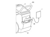
- Figure 1 is a schematic diagram showing the configuration of a radiography system 100.
- Figure 2 is a block diagram showing the configuration of a mobile cart RC.
- the radiation imaging system 100 is installed in a medical facility such as a hospital.
- a user U such as an imaging technician at a medical facility, makes rounds on patients.
- the user U moves to the destination, such as a ward or an operating room, where the patient is located, together with the radiation imaging system 100, and performs radiation imaging on the patient.
- the destination such as a ward or an operating room
- the radiation imaging system 100 performs radiation imaging on the patient.
- a case is shown in which the destination is a ward, and a bed B is installed in the ward.
- a patient S who is a subject, is subjected to radiation imaging while lying on the bed B, for example.
- the radiation imaging system 100 includes an FPD 1, which is a radiation image capturing device, and a mobile radiation irradiation device, a medical cart RC.
- FPD is an abbreviation for Flat Panel Detector.
- the FPD 1 and the medical cart RC can communicate with each other, for example, via wireless communication.
- the radiation imaging system 100 has one or more FPDs 1.
- the radiation imaging system 100 has at least one FPD 1 capable of both still image capture and moving image capture. Furthermore, the radiation imaging system 100 may also have an FPD 1 capable of only still image capture.
- Shooting a still image means acquiring an image of the subject S in response to a single shooting operation.
- the FPD and the radiation irradiation device are synchronized in still image shooting as well, the synchronization is performed immediately before irradiation (at least after the irradiation button is pressed).
- the synchronization in dynamic imaging which will be described later, differs from that in still image shooting in that it is performed before the irradiation button is pressed.
- synchronization of still image capture is a series of sequential request and response operations, in which the following operations are performed for each irradiation: irradiation start request ⁇ FPD preparation for imaging - completion ⁇ irradiation permission ⁇ irradiation ⁇ readout.
- synchronization of dynamic image capture is a non-sequential operation in which sequential exchanges are not performed between the radiation irradiation device and the FPD for each irradiation of radiation.
- synchronization of still image capture and synchronization of dynamic image capture differ.
- the term "synchronization" does not include “synchronization of still image capture” but refers to synchronization of video capture.
- Moving image capture refers to capturing a plurality of images of the subject S by capturing consecutive images of the subject S in response to a single capture operation.
- moving image capture methods a method of capturing images synchronously with pulse irradiation in which radiation such as X-rays is irradiated repeatedly at predetermined time intervals in a pulsed form is called dynamic imaging.
- dynamic photography may be referred to as capturing dynamic images.
- the FPD 1 is a device that generates radiation image data corresponding to the radiation R emitted from the radiation generating device 2 .
- the FPD 1 is configured in a panel shape and is portable.
- the user U can use the FPD 1 by mounting it on an imaging stand.
- the user U can use the FPD 1 by horizontally disposing it between the subject S and a bed B. In this case, the subject S is in a supine position on the bed.
- the user U can also use the FPD 1 by disposing it between the subject S and the bed as shown in FIG. 1.
- the FPD 1 includes, for example, a scintillator, a PD, a TFT switch, and the like.
- PD is an abbreviation for Photo Diode.
- TFT is an abbreviation for Thin Film Transistor.
- the scintillator, PD, TFT switch, and the like are not illustrated.
- the scintillator converts incident radiation R into light.
- the PDs are arranged in a matrix corresponding to the pixels.
- the TFT switches are arranged corresponding to each PD.
- the incident radiation R is converted into light by the scintillator and enters the PD.
- the PD that receives the incident radiation R accumulates the radiation R as an electric charge for each pixel.
- the electric charge accumulated in the PD flows out from the TFT switch to the signal line.
- the electric charge is amplified and A/D converted into radiation image data.
- the radiation image data is output to the mobile cart RC.
- the FPD 1 is an indirect conversion type. However, the FPD 1 may be configured as a direct conversion type that directly converts the radiation R into an electrical signal.
- RIS Radiology Information Systems
- the RIS 40 is a system that manages examinations using radiation equipment, treatment reservations, and examination results.
- the mobile car RC may be capable of communicating with an electronic medical record system and consoles of other radiography systems via the communication network N.
- the mobile car RC may also be capable of communicating with other mobile cars, PACS, other examination devices, bed systems, etc.
- PACS is an abbreviation for Picture Archiving and Communication System.
- the communication network N is wireless, but may be wired.
- the medical cart RC has a radiation generator 2 and a console 3.
- the radiation generating device 2 comprises a device body 21, an irradiation instruction switch 22, a tube 23, a tube support section 24, and a collimator 25.
- the radiation generating device 2 further comprises a generator 213, a storage section 26 for the FPD 1, an optical imaging section 28, and a second display section 29.
- the radiation generating device 2 can be moved by wheels 27 provided on the housing of the device body 21.
- the irradiation instruction switch 22 outputs an operation signal to the device body 21 by operation of the user U. Note that in FIG. 1, the irradiation instruction switch 22 sends an operation signal to the device body 21 via a wired connection. However, the irradiation instruction switch 22 may also send an operation signal to the device body 21 wirelessly.
- the generator 213 receives an imaging instruction signal from the control unit 211, which will be described later, by operating the irradiation instruction switch 22.
- the generator 213 applies a voltage to the tube 23 according to the imaging conditions that have been set in advance.
- the generator 213 also passes a current to the tube 23 according to the imaging conditions.
- the tube 23 generates radiation R (such as X-rays) by applying voltage and current from the generator 213. At this time, the tube 23 generates radiation R at a dose according to the preset imaging conditions and in a manner according to the imaging conditions. The tube 23 irradiates radiation R from an irradiation port.
- radiation R such as X-rays
- the tube support 24 is an arm that supports the tube 23 .
- the tube support 24 has a support part 241 extending upward from the device body 21, and a support part 242 extending forward from an upper part of the support part 241.
- the tip of the support part 242 supports the tube 23.
- the tube support part 24 has a joint mechanism (not shown).
- the tube support part 24 can move the tube 23 in the X-axis direction, the Y-axis direction, and the Z-axis direction by using the joint mechanism.
- the X-axis direction is the left-right direction on the paper surface of FIG. 1.
- the X-axis direction corresponds to the front-rear direction of the radiation generating device 2.
- the Y-axis direction is a direction perpendicular to the paper surface of FIG. 1.
- the Y-axis direction corresponds to the width direction of the radiation generating device 2.
- the Z-axis direction is the up-down direction on the paper surface of FIG. 1.
- the Z-axis direction is the vertical direction.
- the tube support part 24 can rotate the tube 23 around rotation axes parallel to the X-axis, Y-axis, and Z-axis by using the joint mechanism. This allows the tube support part 24 to change the irradiation direction of the radiation R.
- the collimator 25 is attached to an irradiation port of the housing of the bulb 23.
- the collimator 25 focuses the radiation R.
- the collimator 25 causes the irradiation field of the radiation R to have a preset rectangular shape.
- the collimator 25 also includes a lamp button (not shown). When the user operates the lamp button, the collimator 25 irradiates a range that is to become the irradiation field of the radiation R with visible light.
- the optical photographing unit 28 has an optical system such as a lens, and an image pickup element such as a CCD, a CMOS, etc.
- CCD is an abbreviation for Charge Coupled Device
- CMOS is an abbreviation for Complementary Metal Oxide Semiconductor.
- the optical photographing unit 28 is provided in the housing of the collimator 25. Note that the optical photographing unit 28 may be provided in the housing of the bulb 23 or in the bulb support unit 24.
- the optical photographing unit 28 optically photographs the subject S as a subject with visible light and generates optical image data under the control of the control unit 211. Furthermore, the optical photographing unit 28 outputs the optical image data to the control unit 211, etc.
- the optical photographing unit 28 optically photographs the subject S and generates optical image data of a still image or dynamic image (such as a live image).
- the second display unit 29 is configured with an LCD, an EL display, etc.
- LCD is an abbreviation for Liquid Crystal Display.
- EL is an abbreviation for Electro-Luminescence.
- the second display unit 29 displays various information in accordance with the display information, which is input to the second display unit 29 from the control unit 211, which will be described later.
- the second display unit 29 is provided on the outside of the housing of the bulb 23. It is assumed that the bulb 23 is oriented vertically downward. In this case, the second display unit 29 is attached to the cover of the bulb 23 so as to face forward (to the right in FIG. 1 ).
- the storage unit 26 is provided on the rear surface of the apparatus body 21 and stores the FPD 1 when not in use.
- the storage unit 26 can store one or a plurality of FPDs 1.
- the storage unit 26 has the following configuration.
- the storage unit 26 has three slots capable of storing the FPD 1. Each slot has a connector therein that can be connected to a connector (not shown) that the FPD 1 has. Each connector is connected to a power supply circuit 262.
- the power supply circuit 262 can charge the battery of the FPD 1 through the connector.
- only one of the three slots is provided with a connector 261 having a communication function for performing a synchronous process with the radiation generation device 2 for the FPD 1. In Fig. 2, only the connector 261 having the communication function is illustrated.
- the console 3 is configured by a PC, a mobile terminal, or a dedicated device.
- PC is an abbreviation for Personal Computer.
- the console 3 is mounted on the top of the device main body 21.
- the console 3 manages various types of information required for radiographic imaging. Furthermore, the console 3 acquires radiation image data generated by the FPD 1.
- the console 3 can store the radiation image data therein and transmit it to another external device (such as a PACS).
- the device main body 21 and the console 3 are illustrated as being housed in a single housing and integrated together.
- the device main body 21 and the console 3 may be configured as separate bodies.
- the console 3 includes a control unit, a storage unit, a communication unit, a display unit 31, an operation unit 32, and an audio output unit 33.
- the control unit, storage unit, and communication unit of the console 3 are respectively served by the control unit 211, storage unit 212, and communication unit 214 of the radiation generating device 2.
- the console 3 may be configured to include a dedicated control unit, storage unit, and communication unit. In that case, it is preferable that the control unit 211 of the radiation generating device 2 and the control unit of the console 3 are capable of communicating with each other via a wire.
- the control unit 211 is connected to each unit of the radiation generating device 2 except for the bulb 23 so as to be able to communicate with each other.
- the control unit 211 is composed of a CPU, a RAM, etc.
- the CPU reads out various programs stored in the storage unit 212 and loads them in the RAM.
- the CPU then executes various processes in cooperation with the loaded programs. As a result, the CPU controls each part of the radiation generation device 2 and the console 3.
- the storage unit 212 is configured from a non-volatile memory, a HDD, or the like.
- the storage unit 212 stores various programs executed by the control unit 211, and various data such as parameters and files required for executing the programs.
- the storage unit 212 stores programs for executing various processes described below.
- the memory unit 212 also stores various information related to the FPD 1 registered for the medical cart RC. This information includes information on a synchronization state and an expiration date, which will be described later, of the registered FPD 1. This information also includes information indicating for which imaging order, which will be described later, the FPD 1 is used.
- the storage unit 212 also stores examination information and radiography order information for the medical cart RC, which will be described later.
- the communication unit 214 is composed of a communication module and the like.
- the communication unit 214 is capable of transmitting and receiving various signals and various data to and from an external device such as the wirelessly connected FPD 1 or the RIS 40 connected via the communication network N.
- the display unit 31 is configured with an LCD, an EL display, or the like.
- the display unit 31 displays various types of information according to the display information input from the control unit 211 .
- the operation unit 32 includes, for example, one or more of a keyboard, a pointing device, a touch panel, etc.
- the touch panel is integrally formed with the display screen of the display unit 31.
- the touch panel may also be integrally formed with the display screen of the second display unit 29.
- the operation unit 32 accepts operation input from the user U and outputs the operation information to the control unit 211 .
- the audio output unit 33 includes an amplifier, a speaker, etc.
- the audio output unit 33 outputs audio in response to audio information input from the control unit 211.
- the console 3 can acquire examination information for the medical cart RC from the RIS 40 through the communication unit 214.
- new examination information and radiography order information may be added to the console 3 from the RIS 40.
- FIG. 3 shows an example of a display screen 311 of examination information displayed on the display unit 31.
- the control unit 211 displays one or more pieces of examination information in a list 311a on the display screen 311.
- the examination information is information about a scheduled examination.
- Each piece of examination information includes a patient ID, a patient name, an imaging region, a scheduled imaging date and time, a size of the FPD 1 corresponding to imaging, imaging conditions, and the like.
- the control unit 211 accepts a selection input of the examination information displayed in the list 311 a from the user via the operation unit 32 .
- the control unit 211 displays an examination screen 312 for the selected examination information.
- FIG. 4 shows an example of an examination screen 312 for selected examination information.
- the examination screen 312 displays an image display area 312a, a patient information display area 312b, an imaging order display area 312c, and a reading condition setting button 312d.
- an icon F indicating one or more FPDs 1 registered in the console 3 is displayed.
- Each FPD 1 used in a medical facility is assigned a unique serial number.
- a user U can register one or more FPDs 1 to be used for radiography by inputting the serial number from the operation unit 32.
- the control unit 211 requests and acquires information such as specifications of the registered FPD 1 from the FPD 1 and the RIS 40.
- the acquired information such as specifications of the FPD 1 includes, for example, the size that can be photographed, whether dynamic imaging is supported, etc.
- the acquired information such as specifications of the FPD 1 can also be input by the user U from the operation unit 32.
- the control unit 211 may periodically communicate with each registered FPD 1 via the communication unit 214. In this case, the control unit 211 determines whether wireless communication is possible with each FPD 1. For example, an FPD 1 placed in an area of the medical facility away from the medical cart RC cannot perform wireless communication. The control unit 211 may control the display unit 31 so as not to display the icon F of such an FPD 1 in the image display area 312a.
- the patient information display area 312b is an area for displaying patient information of the subject S who is the subject of the examination.
- the reading condition setting button 312d is a button for setting reading conditions at the time of photographing.
- the settable reading conditions include whether or not to execute automatic reading, the reading size at the time of photographing, the reading direction (vertical and horizontal), the reading position, the resolution, and the like.
- the imaging order display area 312c displays an icon C of the imaging order included in the selected examination information.
- the imaging order indicates the radiographic imaging to be performed in the examination whose examination information is displayed in the imaging order display area 312c.
- Multiple radiographic imaging may be scheduled for one examination. In this case, an imaging order is displayed for each individual radiographic imaging. Furthermore, these multiple imaging orders are displayed in order from the top in the order in which the imaging will be performed.
- the storage unit 212 stores a unique order number and imaging conditions for each piece of imaging order information.
- the imaging conditions include the type of imaging, tube voltage, tube current, current time product (mAs value), imaging part, imaging direction, S value, etc.
- the S value is the sensitivity equivalent to the radiation dose during radiography.
- the imaging conditions for a dynamic imaging order include the frame rate.
- the types of photography include still image photography and dynamic photography.
- the photographing conditions include whether or not an additional filter is used and the type thereof, and whether or not a grid is used and the type thereof.
- the additional filter is a piece of equipment used on the radiation generating device 2 side to adjust the amount of radiation during imaging.
- the grid is a device used on the FPD 1 side to reduce scattered radiation occurring in a captured image.
- the icon C of the radiography order displayed in the radiography order display area 312c simply displays part of the radiography conditions. Specifically, the icon C of the radiography order displays the scan size, the region to be radiographed, the type of radiography, etc. In the case of the examination screen 312 illustrated in FIG. 4, it is shown that still image capture, dynamic image capture, and dynamic image capture are performed in this order during the examination.
- the console 3 may receive new imaging order information of the examination information by transmission from the RIS 40 . Furthermore, the user U may operate the operation unit 32 to add new photographing order information to the console 3 . For example, the user U can add a new photographing order by clicking a blank space in the photographing order display area 312c. When the blank space in the photographing order display area 312c is clicked, a dialogue screen for inputting a photographing order is displayed. The user U can input necessary information from the dialogue screen. As a result, an icon C of a new photographing order is displayed in the blank space in the photographing order display area 312c, as shown by the two-dot chain line in FIG. 5.
- the control unit 211 also displays some or all of the content displayed on the display unit 31 on the second display unit 29.
- the control unit 211 can also accept input from the user U via the touch panel of the second display unit 29. The same applies to all of the display content of the display unit 31 described hereinafter.
- the display unit 31 and the second display unit 29 function as a presentation unit.
- the user U captures a radiographic image as follows. First, the user U places the radiation imaging system 100 near the subject S, such as beside the bed B. Then, the user U makes the subject S lie down. Then, the user U adjusts the approximate position and orientation of the tube 23 so that the irradiation port of the housing of the tube 23 faces the imaging site of the subject S. Then, the user U takes out the FPD 1 from the storage unit 26, and places the FPD 1 between the back of the subject S and the bed B.
- the user U finely adjusts the orientation and irradiation field of the tube 23 so that the irradiation axis of the radiation R is perpendicular to the radiation entrance surface of the FPD 1. Then, the user U performs radiation imaging. That is, the user U causes the tube 23 to irradiate the imaging site of the subject S with radiation R. Then, the FPD 1 generates radiation image data of a still image or a dynamic image showing the diagnostic target site.
- the control unit 211 controls the radiation generating device 2 so as to repeatedly irradiate radiation in a pulsed manner at a preset cycle.
- the FPD 1 repeatedly generates radiographic images in synchronization with the irradiation of radiation at a preset cycle, thereby enabling the FPD 1 to generate radiographic image data of a dynamic image made up of a plurality of frame images. For this reason, it is necessary to synchronize the radiation irradiation timing by the radiation generation device 2 and the generation timing of the radiographic image by the FPD 1 with high accuracy.
- the control unit 211 executes a synchronization process to make the radiation generating device 2 and the FPD 1 in a synchronized state using a program in the storage unit 212.
- the control unit 211 functions as a synchronization processing unit.
- the control unit 211 includes an oscillator.
- the oscillator can be configured with a crystal oscillator, a ceramic oscillator, or the like that generates a clock with a predetermined cycle.
- the control unit 211 generates a timing signal and time information using a clock generated by an oscillator.
- the timing signal is a pulse signal that is output every time one or more clocks are generated.
- the time information is a count value that counts up the timing signal.
- the control unit 211 transmits a timing signal and time information to the FPD 1. This causes the FPD 1 to generate a copy signal with the same period as the timing signal. Furthermore, the FPD 1 counts up the copy signal taking into account the time information. This results in a synchronized state in which the control unit 211 and the FPD 1 count up the count value by the same value.
- control unit 211 may transmit information to the FPD 1 in advance that specifies the count value that is the timing for irradiating radiation by the radiation generating device 2. This allows the FPD 1 to generate radiation images at the appropriate timing. Therefore, the FPD 1 can capture good dynamic images.
- FIG. 6 is a flowchart of the synchronization process performed by the control unit 211.
- the synchronization process is performed on the premise that the FPD 1 capable of capturing dynamic images is connected to the connector 261 of the communication-enabled slot. It is preferable that the control unit 211 and the FPD 1 are connected by wire, not wirelessly, by connecting the connectors to each other. This is because the control unit 211 and the FPD 1 can be synchronized with high accuracy by reducing communication interruptions and the effects of noise if they are connected by wire. However, under a good wireless communication environment, the control unit 211 may perform synchronization processing with the FPD 1 via wireless communication.
- the control unit 211 may start the synchronization process when the FPD 1 is connected to the connector 261 with which communication is possible.
- the control unit 211 may also start the synchronization process when a command is input by the user U from the operation unit 32.
- the control unit 211 transmits a synchronization instruction to the FPD 1 (S1).
- the FPD 1 receives the synchronization instruction, it returns a response signal to the control unit 211 (S101).
- the control unit 211 receives the response signal, it initializes the count value of the time information (S2), and then transmits the time information and a timing signal to the FPD 1 (S3).
- the FPD 1 generates a copy signal of the received timing signal (S102), and further counts up the count value of the received time information based on the copy signal (S103).
- S104 a notification of completion of synchronization to the control unit 211
- the control unit 211 ends the synchronization process when it receives a notification of completion of synchronization from the FPD 1 .
- the control unit 211 sets an expiration date for the synchronization process.
- the control unit 211 also transmits information about the expiration date to the FPD 1.
- the control unit 211 also registers the expiration date in the storage unit 212 together with the serial number of the FPD 1 that performed the synchronization process.
- the control unit 211 then monitors the arrival of the expiration date for the synchronization process for the FPD 1 whose expiration date has been registered.
- the FPD 1 may display, on a display unit that displays status information, that the synchronization process has been completed and the FPD 1 is in a synchronous state.
- the FPD 1 may also monitor the expiration date. In this case, the FPD 1 may switch the display of the synchronization status on the display unit to an asynchronous state when the expiration date arrives.
- the control unit 211 executes a synchronization state presentation process for presenting information on the synchronization state of the FPD 1, using a predetermined program stored in the storage unit 212.
- the control unit 211 functions as a synchronization state presentation processing unit.
- the information relating to the synchronization state is information that indicates to the user U whether or not the target FPD 1 is in a synchronized state.
- the "information relating to the synchronization state" will be referred to as "synchronization information”.
- the control unit 211 presents the synchronization information by displaying the display unit 31 and the second display unit 29.
- the synchronization information may be displayed either directly or indirectly.
- a direct display is, for example, a display that clearly indicates that synchronization is in progress.
- An indirect display is, for example, a display that does not clearly indicate that synchronization is in progress but allows the user U to understand that synchronization is in progress.
- the synchronization state presentation process is performed according to a number of patterns described below.
- the radiation imaging system 100 may be a system that performs the synchronization state presentation process in only one of a plurality of patterns described below. Also, the radiation imaging system 100 may be a system that performs the synchronization state presentation process in a combination of two or more of a plurality of patterns.
- the synchronization state presentation process (1) executed by the control unit 211 will be described.
- the control unit 211 presents synchronization information.
- the control unit 211 periodically and repeatedly executes the synchronization state presentation process (1).
- FIG. 7 is a flowchart showing the synchronization state presentation process (1) performed by the control unit 211.
- the control unit 211 displays the examination screen 312 shown in Fig. 5 on the display unit 31 (S11). While the examination screen 312 is being displayed, the user U can select an FPD 1 to be used for imaging from among the registered FPDs 1.
- an icon F of the registered FPD 1 is displayed in the image display area 312a of the examination screen 312, an icon F of the registered FPD 1 is displayed. 5 shows an example in which only one icon F is displayed. However, if a plurality of FPDs 1 are registered in the storage unit 212, the icons F of all the FPDs 1 are displayed in the image display area 312a.
- the control unit 211 determines whether or not there is a selection input for the FPD 1 from the user U (S12). If there is no input, the control unit 211 ends the synchronization state presentation process (1). On the other hand, when the control unit 211 detects a selection input of the FPD 1 from the user U, it highlights the icon of the selected FPD 1. The two-dot chain line in Fig. 8 indicates the highlighting. The highlighting is achieved by changing the color or brightness of the icon F, adding a border around the icon F, or the like. Then, the control unit 211 registers in the storage unit 212 that the selected FPD 1 will be used in the radiography order displayed on the examination screen 312 (S13).
- the control unit 211 refers to the information about the selected FPD1 that is recorded in the storage unit 212. The control unit 211 then determines whether the selected FPD1 is in a synchronized state and whether that state continues (S14).
- the control unit 211 causes the display unit 31 to display a positive screen G1 (S15).
- the positive screen G1 is a screen indicating that the FPD 1 is synchronized. 9, the positive screen G1 displays that the dynamic image capturing order is possible. This display corresponds to "presentation of information regarding the synchronization state.”
- the control unit 211 may refer to the storage unit 212 and display information M1 of the time during which synchronization can be maintained based on information on the expiration date of the synchronization state in the positive screen G1.
- the control unit 211 causes the display unit 31 to display a negative screen G2 (S16).
- the negative screen G2 is a screen indicating that the FPD 1 is not synchronized. 10
- the negative screen G2 displays that synchronization is required by the slot connector 261. This display corresponds to "presentation of synchronization information.”
- control unit 211 goes through S15 or S16 and ends the synchronization state presentation process (1).
- the control unit 211 may end the display of the displayed positive screen G1 or negative screen G2 after a certain period of time has elapsed.
- the control unit 211 may display a confirmation button on the displayed positive screen G1 or negative screen G2. In this case, the control unit 211 may end the display of the screen after receiving an input of the confirmation button from the user U.
- the selected FPD 1 may not have the functionality to perform dynamic imaging.
- the control unit 211 may display a screen indicating that the FPD 1 cannot capture dynamic images.
- the synchronization state presentation process (2) executed by the control unit 211 will be described.
- the control unit 211 presents synchronization information when new photographing order information is acquired by addition or the like or when photographing order information is selected by the user through the synchronization state presentation process (2).
- the control unit 211 periodically and repeatedly executes the synchronization state presentation process (2).
- FIG. 11 is a flowchart showing the synchronization state presentation process (2) performed by the control unit 211.
- the control unit 211 determines whether or not examination information or radiography order information for the medical cart RC has been received from the RIS 40, which is an external device (S21). If the examination information or the photographing order information is not received, the control unit 211 advances the process to S22. On the other hand, if the examination information or the photographing order information is received, the control unit 211 advances the process to S23.
- control unit 211 determines whether or not the user U has added or selected radiography order information from the examination screen 312 (FIG. 5), for example. If there is no such input, the control unit 211 ends the synchronization state presentation process (2). If the above input has been received, the control unit 211 advances the process to S23.
- the control unit 211 refers to information recorded in the storage unit 212 regarding the FPD 1 capable of dynamic radiography that is registered in the storage unit 212. Then, the control unit 211 determines whether or not the registered FPD 1 is in a synchronous state and whether or not the synchronous state continues. As a result, if the synchronized state of the FPD 1 continues, the control unit 211 causes the display unit 31 to display a positive screen indicating that the FPD 1 is in a synchronized state (S24). This positive screen may be the same as the positive screen G1 in FIG. 9 described above. On the other hand, if the synchronized state of the FPD 1 is not maintained, the control unit 211 causes the display unit 31 to display a negative screen (S25). This negative screen may be the same as the negative screen G2 of FIG.
- the control unit 211 may perform the determination in S23 for all FPDs 1 capable of capturing dynamic images. Then, the control unit 211 may display a positive screen if there is at least one FPD 1 that continues to be in a synchronized state. Furthermore, the control unit 211 may display a negative screen when there is not even one FPD 1 that continues to be in a synchronized state.
- control unit 211 goes through S24 or S25 and ends the synchronization status presentation process (2).
- the display of the positive screen or the negative screen is ended in the same manner as in the synchronization state presentation process (1).
- the control unit 211 may cause the display unit 31 to display a screen indicating that the FPD 1 cannot perform dynamic imaging.
- the synchronization state presentation process (3) executed by the control unit 211 will be described.
- the control unit 211 presents synchronization information through the synchronization state presentation process (3).
- the control unit 211 periodically and repeatedly executes the synchronization state presentation process (3).
- the change in the synchronous state corresponds to a case where the synchronous state of the FPD 1 is released due to the expiration date.
- the change in the synchronization state may also include a transition from an asynchronous state to a synchronous state.
- the control unit 211 requires a certain amount of time to elapse from the start of execution of the synchronization process to its completion.
- the change in the synchronization state may also include the moment when the synchronization process is completed.
- FIG. 12 is a flowchart showing the synchronization state presentation process (3) performed by the control unit 211.
- the control unit 211 refers to the information of the FPD 1 registered in the storage unit 212. Then, the control unit 211 judges whether or not there is an FPD 1 whose synchronous state is to be released (S31). In this case, the release of the synchronous state refers to the state immediately before the synchronous state is released.
- the term "immediately before” may be, for example, one to several seconds before, or a shorter time.
- the control unit 211 ends the synchronous state presentation process (3). Furthermore, if there is an FPD 1 whose synchronization state is to be released, the control unit 211 causes the display unit 31 to display the negative screen of Fig. 10 (S32). The negative screen may be the negative screen G2 of Fig. 10. Then, the control unit 211 ends the synchronization state presentation process (3).
- the process for ending the display of the negative screen is the same as in the synchronization status presentation process (1).
- the control unit 211 may monitor the FPD 1 during execution of the synchronization process, and when the synchronization process is completed, cause the display unit 31 to display a positive screen.
- the positive screen may be the positive screen G1 in FIG. In this case, the display of the positive screen is terminated in the same manner as in the synchronous state presentation process (1).
- Fig. 13 is an explanatory diagram showing a state in which the FPD 1 is stored in the storage unit 26.
- Fig. 14 is a flowchart showing the synchronization state presentation process (4) performed by the control unit 211.
- the control unit 211 detects the connection of the FPD 1 to a connector in any of the slots in the storage unit 26 (S41).
- the control unit 211 can detect the connection of the FPD 1 to any of the connectors through the power supply circuit 262 connected to each connector.
- control unit 211 If the control unit 211 does not detect the connection of the FPD 1 to any of the connectors, it ends the synchronization state presentation process (4). Furthermore, when the control unit 211 detects that the FPD 1 is connected to any of the connectors, the control unit 211 refers to information about the FPD 1 that is recorded in the storage unit 212 . Then, the control unit 211 determines whether or not the connected FPD 1 is in a synchronized state and whether or not that state continues (S42).
- the control unit 211 causes the display unit 31 to display a positive screen indicating that the FPD 1 is in a synchronized state (S43).
- This positive screen may be the same as the positive screen G1 in FIG. 9 described above.
- the control unit 211 causes the display unit 31 to display a negative screen G3 of Fig. 16 (S44).
- the negative screen G3 indicates that the FPD 1 is in an asynchronous state. Then, the control unit 211 ends the synchronization state presentation process (4).
- the display of the positive screen or the negative screen G3 is terminated in the same manner as in the synchronous state presentation process (1). Furthermore, there may be cases where the FPD 1 stored in the storage unit 26 does not have a function for performing dynamic imaging. In such cases, the control unit 211 may cause the display unit 31 to display a screen indicating that the FPD 1 cannot capture dynamic images.
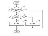
- the synchronization state presentation process (5) executed by the control unit 211 will be described.
- the control unit 211 performs a synchronization state presentation process (5) to present synchronization information.
- the control unit 211 periodically and repeatedly executes the synchronization state presentation process (5).
- FIG. 15 is an explanatory diagram showing a state in which the FPD 1 is being removed from the storage unit 26.
- the control unit 211 detects the removal of the FPD 1 from the connector in any of the slots in the storage unit 26 (S46).
- the control unit 211 can detect the removal of the FPD 1 from any of the connectors through the power supply circuit 262 connected to each connector.
- control unit 211 If the control unit 211 does not detect the removal of the FPD 1 from any of the connectors, it ends the synchronization state presentation process (5). Furthermore, when removal of the FPD 1 from any of the connectors is detected, the control unit 211 refers to information about the removed FPD 1 that is recorded in the storage unit 212 . Then, the control unit 211 determines whether or not the removed FPD 1 is in a synchronized state and whether or not the synchronized state continues (S47).
- the control unit 211 causes the display unit 31 to display a positive screen indicating that the FPD 1 is in a synchronized state (S48).
- This positive screen may be the same as the positive screen G1 in FIG. 9 described above.
- the control unit 211 causes the display unit 31 to display the negative screen G3 of FIG. 16 (S49). Then, the control unit 211 ends the synchronization state presentation process (5).
- the display of the positive screen or the negative screen G3 is terminated in the same manner as in the synchronous state presentation process (1).
- the control unit 211 may cause the display unit 31 to display a screen indicating that the FPD 1 cannot capture dynamic images.
- the control unit 211 presents information regarding both the synchronous state and the asynchronous state of the FPD 1. From the viewpoint of drawing the attention of the user U, the presentation of the synchronous state is more important than the presentation of the asynchronous state. Therefore, in the synchronous state presentation processes (1), (2), (4), and (5), the control unit 211 may omit the presentation of the synchronous state.
- each screen presenting synchronization information may be supplemented with information identifying the FPD 1.
- information identifying the FPD 1 For example, specific information such as the type, model number, and serial number of the target FPD 1 may also be displayed on each screen.
- the control unit 211 executes a battery remaining capacity display process for displaying information related to the remaining battery capacity of the FPD 1, using a predetermined program stored in the storage unit 212.
- the control unit 211 functions as a battery remaining capacity display processing unit.
- the information relating to the remaining battery level is information that indicates to the user U whether the remaining battery level is appropriate for the target FPD 1 to perform dynamic imaging.
- the "information relating to the remaining battery level" will be referred to as "battery information”.
- the control unit 211 presents the battery information by displaying the display unit 31 and the second display unit 29.
- the battery information may be displayed either directly or indirectly.
- a direct display is, for example, a display that clearly indicates the remaining battery charge itself or whether the remaining battery charge is sufficient.
- An indirect display is, for example, a display that allows the user U to understand whether dynamic shooting is possible or not depending on the remaining battery charge.
- the remaining battery capacity display process is performed according to a number of patterns which will be described below.
- the radiation imaging system 100 may execute the battery remaining capacity display process in only one of a plurality of patterns described below. Also, the radiation imaging system 100 may execute the battery remaining capacity display process in a combination of two or more of a plurality of patterns.
- the battery remaining capacity display process (1) executed by the control unit 211 will be described.
- the control unit 211 presents battery information.
- the control unit 211 periodically and repeatedly executes the battery remaining capacity display process (1).
- FIG. 18 is a flowchart showing the battery remaining capacity display process (1) performed by the control unit 211.
- the control unit 211 displays the examination screen 312 shown in FIG. 5 on the display unit 31 (S51).
- the control unit 211 determines whether or not there is a selection input for the FPD 1 from the user U (S52). If there is no input, the control unit 211 ends the remaining battery level presentation process (1). On the other hand, when the control unit 211 detects a selection input of the FPD 1 from the user U, the control unit 211 performs the following process: The control unit 211 registers in the storage unit 212 that the selected FPD 1 will be used in the radiography order displayed on the examination screen 312 (S53).
- control unit 211 communicates with the selected FPD1 and requests the current remaining battery level (S54). The control unit 211 then obtains the current remaining battery level in response to the response from the FPD1.
- the control unit 211 judges whether the remaining battery level of the selected FPD 1 is equal to or greater than a predetermined value (S55).
- the predetermined value here indicates a remaining battery level at which dynamic radiography can be performed. This value may be set in advance.
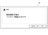
- the control unit 211 causes the display unit 31 to display a positive screen (S56).
- the positive screen is a screen that clearly indicates that the remaining battery charge is sufficient for dynamic imaging. This screen may be, for example, the same as the positive screen G1 in Fig. 9.
- Fig. 9 shows that the remaining battery power is sufficient to capture a dynamic image, and therefore, capture is possible. This display corresponds to "information regarding the remaining battery power.”
- the control unit 211 may display the remaining battery charge instead of the information M1 of FIG. 9 showing the time during which synchronization can be maintained.
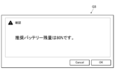
- the control unit 211 causes the display unit 31 to display a negative screen G4 (S57).
- the negative screen G4 is a screen that clearly indicates that the remaining battery level is insufficient for dynamic radiography. 19, the negative screen G4 displays that the FPD 1 needs to be charged by the connector 261 of any of the slots. This display corresponds to "information regarding the remaining battery capacity.”
- control unit 211 goes through S56 or S57 and ends the remaining battery level presentation process (1).
- the control unit 211 may end the display of the displayed positive screen or negative screen G4 after a certain period of time has elapsed.
- the control unit 211 may display a confirmation button on the displayed positive screen or negative screen G4. In this case, the control unit 211 may end the display of the screen after receiving input of the confirmation button.
- the control unit 211 may display the "information regarding the remaining battery power" in stages. For example, it is assumed that a recommended battery remaining capacity and a smaller feasible battery remaining capacity are set.
- the recommended battery remaining capacity is a value that is sufficient to perform dynamic radiography.
- the feasible battery remaining capacity is a value that allows dynamic radiography to be performed.
- the control unit 211 may display a screen showing a recommended remaining battery level when the FPD 1 has a value less than the recommended remaining battery level and equal to or greater than the executable remaining battery level (see FIG. 22). Also, the control unit 211 may display the executable remaining battery level when the FPD 1 has a value less than the executable remaining battery level (see FIG. 23). A display encouraging charging of the battery of the FPD 1 may be added to these screens.
- the control unit 211 may perform the synchronization status presentation process (1) and the battery remaining capacity presentation process (1) in parallel. In that case, the control unit 211 may perform the displays based on each process at different times. The control unit 211 may also divide the display area into two and perform each display.
- control unit 211 may perform individual display for all combinations of the determination results of the respective processes. For example, the control unit 211 may perform the following display. (i) An indication that the FPD 1 is synchronizing and the battery level is sufficient. (ii) FPD1 is synchronizing but the battery level is insufficient. (iii) An indication that the FPD 1 is asynchronous and the battery level is sufficient. (iv) FPD1 is out of sync and the battery is low.
- the battery remaining capacity display process (2) executed by the control unit 211 will be described.
- the control unit 211 presents the battery information when new photographing order information is acquired by addition or the like or when photographing order information is selected by the user through the battery remaining amount presentation process (2).
- the control unit 211 periodically and repeatedly executes the battery remaining capacity display process (2).
- FIG. 20 is a flowchart showing the battery remaining capacity display process (2) performed by the control unit 211.
- the control unit 211 determines whether or not examination information or radiography order information for the medical cart RC has been received from the RIS 40 (S61). If the examination information or the photographing order information is not received, the control unit 211 advances the process to S62. On the other hand, if the examination information or the photographing order information is received, the control unit 211 advances the process to S63.
- control unit 211 determines whether or not the user U has added or selected radiography order information from the examination screen 312 (FIG. 5). If there is no such input, the control unit 211 ends the battery remaining capacity display process (2). If the above input has been received, the control unit 211 advances the process to S63.
- control unit 211 communicates with the FPD1 capable of dynamic imaging registered in the memory unit 212, and requests the current remaining battery level. The control unit 211 then obtains the current remaining battery level in response to the FPD1.
- the control unit 211 determines whether or not the remaining battery level of the selected FPD 1 is equal to or greater than the value that allows dynamic radiography (S64). As a result, if the remaining battery level of the selected FPD 1 is equal to or greater than the level at which dynamic radiography is possible, the control unit 211 causes the display unit 31 to display a positive screen (S65).
- This positive screen may be the positive screen G1 in FIG. 9, as in the above-described battery remaining capacity presentation process (1).
- the control unit 211 causes the display unit 31 to display a negative screen (S66).
- the negative screen may be the same screen as the negative screen G4 in FIG. 19.
- the control unit 211 may perform the determination in S64 for all FPDs 1 capable of capturing dynamic images. If there is even one FPD 1 whose remaining battery charge is equal to or greater than the value that allows dynamic imaging, the control unit 211 may display a positive screen. Also, the control unit 211 may display a negative screen when there is no FPD 1 whose remaining battery charge is equal to or greater than the value that allows dynamic imaging.
- control unit 211 goes through S65 or S66 and ends the remaining battery level presentation process (2).
- the display of the positive screen or the negative screen is ended in the same manner as in the battery remaining capacity display process (1).
- the gradual display of the "information relating to the battery remaining capacity" is the same as in the battery remaining capacity presentation process (1).
- the control unit 211 may perform the synchronization status presentation process (2) and the battery remaining capacity presentation process (2) in parallel. This case is the same as the case where the synchronization status presentation process (1) and the battery remaining capacity presentation process (1) are performed in parallel.
- the remaining battery power display process (3) executed by the control unit 211 will be described.
- the control unit 211 displays battery information through a remaining battery charge display process (3).
- the control unit 211 periodically and repeatedly executes the remaining battery level display process (3).
- FIG. 21 is a flowchart showing the battery remaining capacity display process (3) performed by the control unit 211.
- the control unit 211 communicates with the FPD 1 capable of dynamic radiography registered in the storage unit 212 and requests the current remaining battery level (S71). If there are multiple FPDs 1 capable of dynamic radiography, the control unit 211 requests the current remaining battery levels from all of those FPDs 1. Then, the control unit 211 acquires the current remaining battery level value from the response of the FPD 1 .
- the control unit 211 compares the remaining battery level of the selected FPD 1 with a first threshold value (S72).
- a first threshold value (S72)
- the control unit 211 prepares two threshold levels, a first threshold level and a second threshold level, where the first threshold level is greater than the second threshold level.
- the first threshold value indicates a recommended battery remaining capacity value that is sufficient to perform dynamic radiography
- the second threshold value indicates a viable battery remaining capacity value that allows dynamic radiography to be performed.
- control unit 211 ends the remaining battery level presentation process (3).
- the control unit 211 may display on the display unit 31 that the remaining battery charge of the FPD 1 is equal to or greater than the recommended remaining battery charge.
- the control unit 211 compares the remaining battery charge value with a second threshold (S73). If the remaining battery charge value of the FPD 1 is not less than the second threshold value, the first screen G5 of FIG. 22 is displayed on the display unit 31 (S74).
- the second screen G6 of FIG. 23 is displayed on the display unit 31 (S75).
- the first screen G5 is a screen showing that the remaining battery charge value of the FPD 1 is greater than the executable battery charge but less than the recommended battery charge.
- the second screen G6 is a screen showing that the remaining battery charge value of the FPD 1 is less than the executable battery charge.
- control unit 211 goes through S74 or S75 and ends the remaining battery level display process (3).
- the control unit 211 may set only one threshold value for the remaining battery capacity and make a determination.
- the threshold value is set to only the second threshold value.
- the control unit 211 omits step S72 in the battery remaining amount display process (3).
- the control unit 211 may end the process when it determines NO in step S73.
- the control unit 211 may display on the display unit 31 that the FPD 1 has an executable remaining battery amount or more when it determines NO in step S73.
- control unit 211 may perform the battery level display process (3) for the FPD 1 with the highest remaining battery level.
- the display of the first screen G5 or the second screen G6 is terminated in the same manner as in the display of the screen in the battery remaining capacity display process (1).
- the remaining battery power display process (4) executed by the control unit 211 will be described.
- the control unit 211 displays battery information.
- the control unit 211 periodically and repeatedly executes the remaining battery level display process (4).
- FIG. 24 is a flowchart showing the remaining battery power display process (4) performed by the control unit 211.
- the control unit 211 detects the connection of the FPD 1 to a connector in any of the slots in the storage unit 26 (S81).
- control unit 211 If the control unit 211 does not detect the connection of the FPD 1 to any of the connectors, it ends the remaining battery level presentation process (4). Furthermore, if the control unit 211 detects that the FPD 1 is connected to any of the connectors, the process proceeds to S82.
- control unit 211 communicates with the connected FPD1 and requests the current remaining battery level. The control unit 211 then obtains the current remaining battery level in response to the FPD1.
- the control unit 211 determines whether or not the remaining battery level of the connected FPD 1 is equal to or greater than the value that allows dynamic imaging (S83). As a result, if the remaining battery level of the connected FPD 1 is equal to or greater than the level at which dynamic radiography is possible, the control unit 211 causes the display unit 31 to display a positive screen (S84). Note that this positive screen may be the positive screen G1 in Fig. 9, as in the case of the above-mentioned battery level presentation process (1).
- the control unit 211 causes the display unit 31 to display a negative screen (S85).
- this negative screen may be the negative screen G4 in FIG. 19, as in the case of the battery remaining level presentation process (1) described above.
- control unit 211 goes through S84 or S85 and ends the remaining battery level display process (4).
- the display of the positive screen or the negative screen is ended in the same manner as in the battery remaining capacity display process (1).
- the stepwise display of the "information relating to the battery remaining capacity" is the same as in the battery remaining capacity display process (1).
- control unit 211 may cause the display unit 31 to display a screen indicating that the FPD 1 cannot capture dynamic images.
- the control unit 211 may perform the synchronization status presentation process (4) and the battery remaining capacity presentation process (4) in parallel. This case is the same as the case where the synchronization status presentation process (1) and the battery remaining capacity presentation process (1) are performed in parallel.
- the remaining battery power display process (5) executed by the control unit 211 will be described.
- the control unit 211 displays battery information in a battery remaining capacity display process (5).
- the control unit 211 periodically and repeatedly executes the remaining battery level display process (5).
- FIG. 25 is a flowchart showing the remaining battery power display process (5) performed by the control unit 211.
- the control unit 211 detects removal of the FPD 1 from the connector in any of the slots in the storage unit 26 (S91).
- control unit 211 If the control unit 211 does not detect the removal of the FPD 1 from any of the connectors, it ends the remaining battery level presentation process (5). Moreover, if the control unit 211 detects removal of the FPD 1 from any of the connectors, the process proceeds to S92.
- control unit 211 communicates with the removed FPD 1 and requests the current remaining battery level. The control unit 211 then obtains the current remaining battery level based on the response from the FPD 1.
- the control unit 211 determines whether or not the remaining battery level of the removed FPD 1 is equal to or greater than a level sufficient for dynamic imaging (S93). As a result, if the remaining battery level of the removed FPD 1 is equal to or greater than the level at which dynamic radiography is possible, the control unit 211 causes the display unit 31 to display a positive screen (S94). Note that this positive screen may be the positive screen G1 in Fig. 9, as in the case of the above-mentioned battery level presentation process (1).
- the control unit 211 causes the display unit 31 to display a negative screen (S95).
- this negative screen may be the negative screen G4 in FIG. 19, as in the case of the battery level display process (1) described above.
- control unit 211 goes through S94 or S95 and ends the remaining battery level display process (5).
- the display of the positive screen or the negative screen is ended in the same manner as in the battery remaining capacity display process (1).
- the stepwise display of the "information relating to the battery remaining capacity" is the same as in the battery remaining capacity display process (1).
- control unit 211 may cause the display unit 31 to display a screen indicating that the FPD 1 cannot capture dynamic images.
- the control unit 211 may perform the synchronization status presentation process (5) and the battery remaining capacity presentation process (5) in parallel. This case is the same as the case where the synchronization status presentation process (1) and the battery remaining capacity presentation process (1) are performed in parallel.
- the control unit 211 displays information in two cases.
- the two cases are when the remaining battery capacity of the FPD 1 is sufficient for capturing dynamic images and when it is insufficient. From the viewpoint of alerting the user U, of the above two cases, the case where the remaining battery power is insufficient for capturing dynamic images is of higher importance. Therefore, in the battery remaining power presentation processes (1), (2), (4), and (5), the control unit 211 may omit presenting information when the remaining battery power of the FPD 1 is sufficient for capturing dynamic images.
- each screen that displays battery information may include information that identifies the FPD 1.
- each screen may display specific information such as the type, model number, and serial number of the target FPD 1.
- the control unit 211 executes an equipment information presentation process for presenting information on equipment required for capturing a radiographic image, using a predetermined program stored in the storage unit 212.
- the control unit 211 functions as an equipment information presentation processing unit.
- Equipment required for capturing a radiation image includes an FPD, a grid, an additional filter, etc. Examples of equipment are not limited to these.
- the equipment includes any equipment that may be required depending on the imaging conditions and the imaging mode. In the following description, an example in which the equipment includes an FPD and a grid will be described.
- the equipment-related information is information indicating the equipment required for the target shooting. This information may include information that specifically identifies the equipment, such as the specifications, format, model, and type of the equipment.
- equipment information information regarding equipment
- the equipment information presentation process is performed according to a number of patterns which will be described below.
- the radiation imaging system 100 may perform the equipment information presentation process in only one of a plurality of patterns described below. Also, the radiation imaging system 100 may perform the equipment information presentation process in a combination of two or more of the plurality of patterns.
- the device information presentation process (1) executed by the control unit 211 will be described.
- the control unit 211 presents equipment information.
- the control unit 211 periodically and repeatedly executes the device information presentation process (1).
- FIG. 26 is a flow chart showing the equipment information presentation process (1) performed by the control unit 211.
- the control unit 211 displays the examination screen 312 shown in FIG. 5 on the display unit 31 (S111).
- the control unit 211 determines whether or not there is a selection input for the FPD 1 from the user U (S112). If there is no input, the control unit 211 ends the equipment information presentation process (1). On the other hand, when the control unit 211 detects a selection input of the FPD 1 from the user U, the control unit 211 performs the following process: The control unit 211 registers in the storage unit 212 that the selected FPD 1 will be used in the radiography order displayed on the examination screen 312 (S113).
- the control unit 211 identifies the equipment information based on the radiography order information of the medical cart RC stored in the storage unit 212 (S114).
- the equipment information is the specifications, format, model, type, etc. of the FPD 1 and grid equipment that are necessary or appropriate for the radiography order.
- control unit 211 specifies the FPD 1 from among the FPDs 1 registered in the storage unit 212. However, the control unit 211 may specify an FPD 1 from outside the range of the registered FPDs 1. In addition, when there are multiple pieces of radiography order information for the mobile cart RC stored in the memory unit 212, the control unit 211 may identify the equipment information based on all of the radiography order information.
- the control unit 211 causes the display unit 31 to display a device information presentation screen G7 shown in FIG. 27 on which the identified device information is displayed (S115). Then, the control unit 211 ends the device information presentation process (1).
- the control unit 211 may end the display of the displayed equipment information presentation screen G7 after a certain period of time has elapsed. Alternatively, the control unit 211 may display a confirmation button on the displayed equipment information presentation screen G7. In this case, the control unit 211 may end the display of the screen after receiving input from the confirmation button.
- the control unit 211 may perform the equipment information presentation process (1) and the synchronization status presentation process (1) or the battery remaining capacity presentation process (1) in parallel. In that case, the control unit 211 may perform the display based on each process at different times. The control unit 211 may also divide the display area and perform each display.
- Equipment information presentation process (2) The device information presentation process (2) executed by the control unit 211 will be described.
- the control unit 211 presents equipment information when new photographing order information is acquired by addition or the like or when photographing order information is selected by the user.
- the control unit 211 periodically and repeatedly executes the device information presentation process (2).
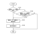
- FIG. 28 is a flowchart showing the device information presentation process (2) performed by the control unit 211.
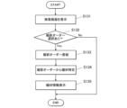
- the control unit 211 determines whether or not examination information or radiography order information for the medical cart RC has been received from the RIS 40, which is an external device (S121). If the examination information or the photographing order information is not received, the control unit 211 advances the process to S122. On the other hand, if the examination information or the photographing order information is received, the control unit 211 advances the process to S123.
- control unit 211 determines whether or not the user U has added or selected radiography order information from the examination screen 312 (FIG. 5). If there is no input, the control unit 211 ends the equipment information presentation process (2). If the above input has been received, the control unit 211 advances the process to S123.
- the control unit 211 specifies equipment information based on the radiography order information added in S121 or S122.
- the equipment information is the specifications, format, model, type, etc. of the FPD 1 and the grid equipment necessary or appropriate for the radiography indicated by the radiography order information.
- the control unit 211 specifies the FPD 1 from among the FPDs 1 registered in the storage unit 212.
- the control unit 211 may specify an FPD 1 from outside the range of registered FPDs 1.
- the control unit 211 causes the display unit 31 to display a device information presentation screen G7 shown in FIG. 27 on which the identified device information is displayed (S124). Then, the control unit 211 ends the device information presentation process (2).
- the display of the equipment information presentation screen G7 is ended in the same manner as in the equipment information presentation process (1).
- the control unit 211 may perform the equipment information presentation process (2) and the synchronization state presentation process (2) or the battery remaining capacity presentation process (2) in parallel. This case is the same as the case where the equipment information presentation process (1) and the synchronization state presentation process (1) or the battery remaining capacity presentation process (1) are performed in parallel.
- Equipment information presentation process (3) The device information presentation process (3) executed by the control unit 211 will be described.
- the control unit 211 presents equipment information.
- the control unit 211 periodically and repeatedly executes the device information presentation process (3).
- FIG. 29 is a flow chart showing the device information presentation process (3) performed by the control unit 211.
- the control unit 211 displays the examination screen 312 shown in FIG. 5 on the display unit 31 (S131).
- the user U can select an image capture order to be executed by selecting an icon C of an image capture order displayed on the examination screen 312 using the operation unit 32 .
- the control unit 211 determines whether or not a radiography order has been selected and input by the user U (S132). If no input has been made, the control unit 211 ends the equipment information presentation process (3). On the other hand, when the control unit 211 detects a selection input of a radiography order from the user U, the control unit 211 performs the following process: The control unit 211 registers in the storage unit 212 that the selected radiography order is a subject of radiography (S133).
- the control unit 211 identifies the equipment information based on the radiography order selected by the user U (S134).
- the equipment information is the specifications, format, model, type, etc. of the FPD 1 and grid equipment necessary or appropriate for the radiography indicated by the radiography order information.
- the control unit 211 preferably identifies the FPD1 from among the FPD1s registered in the storage unit 212. However, the control unit 211 may identify an FPD1 from outside the range of registered FPD1s.
- the control unit 211 causes the display unit 31 to display a device information presentation screen G7 shown in FIG. 27 on which the identified device information is displayed (S135). Then, the control unit 211 ends the device information presentation process (3).
- the display of the equipment information presentation screen G7 is terminated in the same manner as in the equipment information presentation process (1).
- Equipment information presentation process (4) The device information presentation process (4) executed by the control unit 211 will be described.
- the control unit 211 presents equipment information.
- the control unit 211 periodically and repeatedly executes the device information presentation process (4).
- Preparatory operations for imaging include moving the medical cart RC, adjusting the position and orientation of the tube 23 on the tube support portion 24, and the like.
- the movement of the medical cart RC can be detected by an acceleration sensor provided somewhere on the medical cart RC, a rotation sensor provided on the wheels 27, etc.
- the adjustment of the position and orientation of the tube 23 can be detected by an acceleration sensor provided near the tube 23 on the tube support part 24.
- the adjustment of the orientation can be detected by an acceleration sensor and a rotation sensor provided in the joint mechanism of the tube support part 24.
- the control unit 211 illustrates an example of the equipment information presentation process (4) in which equipment information is presented by moving the medical cart RC.
- FIG. 30 is a flow chart showing the device information presentation process (4) performed by the control unit 211.
- the control unit 211 determines whether or not movement of the medical cart RC has occurred (S141). If the movement of the medical cart RC is not detected, the control unit 211 ends the equipment information presentation process (4).
- the control unit 211 identifies the equipment information based on the radiography order information of the medical examination cart RC stored in the storage unit 212 (S142).
- the equipment information is the specifications, format, model, type, etc. of the FPD1 and grid equipment necessary or appropriate for the radiography indicated by the radiography order information.
- control unit 211 specifies the FPD 1 from among the FPDs 1 registered in the storage unit 212. However, the control unit 211 may specify an FPD 1 from outside the range of the registered FPDs 1. In addition, when there are multiple pieces of radiography order information for the mobile cart RC stored in the memory unit 212, the control unit 211 may identify the equipment information based on all of the radiography order information.
- the control unit 211 causes the display unit 31 to display a device information presentation screen G7 shown in FIG. 27 on which the identified device information is displayed (S143). Then, the control unit 211 ends the device information presentation process (4).
- the display of the equipment information presentation screen G7 is terminated in the same manner as in the equipment information presentation process (1).
- the control unit 211 can select whether to execute or not execute the various processes described above depending on the settings.
- the various processes refer to synchronization status presentation processes (1) to (5), remaining battery capacity presentation processes (1) to (5), and device information presentation processes (1) to (4).
- the above settings can be made by the user U through the operation unit 32.
- the operation unit 32 functions as a setting input unit.
- the control unit 211 causes the display unit 31 to present synchronization information of the FPD 1 . If the synchronization information is presented when the FPD 1 is stored in the storage unit 26, the user U will pay attention to the synchronization information. This enables the system 100 to allow the user U to accurately recognize the synchronization information. Furthermore, the system 100 can reduce the chance of the user U making a mistake in capturing dynamic images using an unsynchronized FPD 1 .
- the control unit 211 causes the display unit 31 to display the synchronization information of the FPD 1 . If the synchronization information is presented when the FPD 1 is removed from the storage unit 26, the user U will pay attention to the synchronization information. This enables the system 100 to allow the user U to accurately recognize the synchronization information. Furthermore, the system 100 can reduce the chance of the user U making a mistake in capturing dynamic images using an unsynchronized FPD 1 .
- the control unit 211 causes the display unit 31 to present synchronization information of the FPD 1. If the synchronization information is presented when the FPD 1 is selected, the user U will pay attention to the synchronization information. Furthermore, when the FPD 1 is selected, the user U often focuses his or her attention on the display unit 31. This enables the system 100 to allow the user U to accurately recognize the synchronization information. Furthermore, the system 100 can reduce the chance of the user U making a mistake in capturing dynamic images using an unsynchronized FPD 1 .
- the control unit 211 when radiography order information is acquired from an external device, or when radiography order information is added, the control unit 211 causes the display unit 31 to present synchronization information of the FPD 1.
- the control unit 211 when the imaging order information is acquired, for example, when the user selects the imaging order information, the control unit 211 causes the display unit 31 to present the synchronization information of the FPD 1. If the synchronization information is presented when the photographing order information is acquired, the user U will pay attention to the synchronization information. Furthermore, when the photographing order information is acquired, the user U often focuses his or her attention on the display unit 31. This enables the system 100 to allow the user U to accurately recognize the synchronization information. Furthermore, the system 100 can reduce the chance of the user U making a mistake in capturing dynamic images using an unsynchronized FPD 1 .
- the control unit 211 causes the display unit 31 to present the synchronization information of the FPD 1.
- a change in the synchronization state of the FPD 1 is an important matter for the user U who is taking dynamic images. In this way, the system 100 can allow the user U to promptly and accurately recognize this important matter from the time it occurs. Furthermore, it is difficult for the user U to recognize a change in the synchronization state that is not apparent from the appearance of the FPD 1. However, the system 100 makes it possible for the user U to accurately recognize a change in the synchronization state. Furthermore, the system 100 can reduce the chance of the user U making a mistake in capturing dynamic images using an unsynchronized FPD 1 .
- the control unit 211 causes the display unit 31 to present information M1 on the time during which the FPD 1 can maintain the synchronous state. Therefore, the system 100 can allow the user U to accurately recognize the time during which the FPD 1 can maintain the synchronized state. Furthermore, the system 100 can reduce the chance of the user U making a mistake in capturing dynamic images with an FPD 1 whose synchronization time has expired.
- the control unit 211 causes the display unit 31 to display battery information of the FPD 1 at a determined timing. Therefore, the system 100 can draw the user U's attention to the battery information, as compared to a case in which the battery information is constantly presented.
- the control unit 211 causes the display unit 31 to display battery information of the FPD 1. If the battery information is presented when the FPD 1 is stored in the storage unit 26, the user U will pay attention to the battery information. This enables the system 100 to allow the user U to accurately recognize the battery information. Furthermore, the system 100 can reduce the chance of the user U making a mistake in capturing dynamic images using the FPD 1 that has a low battery.
- the control unit 211 causes the display unit 31 to display battery information of the FPD 1. If the battery information is presented when the FPD 1 is removed from the storage unit 26, the user U will pay attention to the battery information. This enables the system 100 to allow the user U to accurately recognize the battery information. Furthermore, the system 100 can reduce the chance of the user U making a mistake in capturing dynamic images using an FPD 1 that has a low battery.
- the control unit 211 causes the display unit 31 to display battery information of the FPD 1. If the battery information is presented when the FPD 1 is selected, the user U will pay attention to the battery information. Furthermore, when the FPD 1 is selected, the user U often focuses his or her attention on the display unit 31. This enables the system 100 to allow the user U to accurately recognize the battery information. Furthermore, the system 100 can reduce the chance of the user U making a mistake in capturing dynamic images using an FPD 1 that has a low battery.
- the control unit 211 when radiography order information is acquired from an external device or when radiography order information is added, the control unit 211 causes the display unit 31 to present battery information of the FPD 1.
- radiography order information is acquired, such as when radiography order information is selected by a user
- the control unit 211 causes the display unit 31 to present battery information of the FPD 1. If the battery information is presented when the photographing order information is acquired, the user U will pay attention to the battery information. Furthermore, when the photographing order information is acquired, the user U often focuses his or her attention on the display unit 31. This enables the system 100 to allow the user U to accurately recognize the battery information. Furthermore, the system 100 can reduce the chance of the user U making a mistake in capturing dynamic images using an FPD 1 that has a low battery.
- the control unit 211 causes the display unit 31 to present battery information of the FPD 1.
- a decrease in the remaining battery power of the FPD 1 is an important matter for the user U who is taking dynamic images. In this way, the system 100 can promptly and accurately make the user U aware of this important matter from the time it occurs. In addition, it is difficult for the user U to recognize a decrease in the remaining battery power, which is not visible from the outside of the FPD 1. However, the system 100 makes it possible for the user U to accurately recognize the change in the remaining battery power. Furthermore, the system 100 can reduce the chance of the user U making a mistake in capturing dynamic images using an FPD 1 that has a low battery.
- the control unit 211 causes the display unit 31 to present equipment information relating to equipment required for shooting at a predetermined timing. Therefore, the system 100 can draw the user U's attention to the equipment information, as compared to a case in which the equipment information is constantly presented.
- the control unit 211 causes the display unit 31 to present equipment information. If the equipment information is presented when the FPD 1 is selected, the user U will pay attention to the equipment information. Furthermore, when the FPD 1 is selected, the user U often focuses his or her attention on the display unit 31. This enables the system 100 to allow the user U to accurately recognize the equipment information. Furthermore, the FPD 1 that will perform imaging is often selected at the preparation stage before imaging using the FPD 1 is performed. This allows the system 100 to enable the user U to properly prepare the equipment and smoothly prepare for photography. Furthermore, the system 100 can reduce mistakes made by the user U, such as a lack of equipment or an incorrect selection of equipment, that prevent imaging using the FPD 1 from being performed.
- the control unit 211 causes the display unit 31 to present equipment information. If the equipment information is presented when the photographing order information is acquired, the user U will pay attention to the equipment information. Furthermore, when the photographing order information is acquired, the user U often focuses his or her attention on the display unit 31. This enables the system 100 to allow the user U to accurately recognize the equipment information. Furthermore, when an imaging order is received, the user U often starts preparations for imaging using the FPD 1 . This allows the system 100 to allow the user U to properly prepare the equipment and smoothly prepare for photography. Furthermore, the system 100 can reduce mistakes made by the user U, such as a lack of equipment or an incorrect selection of equipment, that prevent imaging using the FPD 1 from being performed.
- the control unit 211 causes the display unit 31 to display equipment information. If the equipment information is presented when an image capture order is selected, the user U will pay attention to the equipment information. Furthermore, when selecting an image capture order, the user U often focuses his or her attention on the display unit 31. This enables the system 100 to allow the user U to accurately recognize the equipment information. Furthermore, when an imaging order is selected, the user U often starts preparations for imaging using the FPD 1 . This allows the system 100 to allow the user U to properly prepare the equipment and smoothly prepare for photography. Furthermore, the system 100 can reduce mistakes made by the user U, such as a lack of equipment or an incorrect selection of equipment, that prevent imaging using the FPD 1 from being performed.
- the control unit 211 causes the display unit 31 to present equipment information. If the equipment information is presented when a preparation operation for shooting is detected, the user U will pay attention to the equipment information. This allows the system 100 to allow the user U to accurately recognize the equipment information. Furthermore, the system 100 can provide equipment information to the user U who is preparing to shoot at the right time. Therefore, the user U can properly prepare the equipment and smoothly prepare for photography. Furthermore, the system 100 can reduce mistakes made by the user U, such as a lack of equipment or an incorrect selection of equipment, that prevent imaging using the FPD 1 from being performed.
- the radiation imaging system 100 has a mobile radiology cart RC as a mobile radiation irradiation device. This makes it possible to move to various locations within the medical facility and perform radiation image capture. Furthermore, the control unit 211 can perform a synchronization state presentation process, a battery remaining amount presentation process, or an equipment information presentation process. Therefore, in radiographic image capture that involves movement due to rounds, the system 100 can provide accurate imaging support.
- the display units 31 and 29 are disposed on the console 3, the frame of the tube 23, and the device body 21. This allows the user U to receive various pieces of information at a position appropriate for the work being performed.
- the system 100 presents various information by sound, light, or vibration, allowing the user U to perform shooting without gazing at the display unit. Therefore, the system 100 can improve the operability of the user U.
- the radiation imaging system 100 has an operation unit 32 into which a setting for whether to execute or not execute presentation on the display unit 31 is input. Therefore, it is possible to receive the presentation of information suitable for the environment in which the radiation imaging system 100 is used. In addition, since the presentation of unnecessary information can be avoided, it is possible to more accurately provide necessary information to the user U. Furthermore, in the imaging order display area (reference numeral 312c in FIG. 4), when there is no imaging order for dynamic imaging or when imaging has already been performed even if there is an imaging order for dynamic imaging, the presentation of unnecessary information can be avoided by not presenting the synchronization state.
- the subject S When capturing a radiation image, the subject S is positioned in advance. During positioning, an offset calibration image is captured using the FPD 1.
- the offset calibration image is an image obtained by capturing an image using the FPD 1 without irradiating radiation. A plurality of offset calibration images are acquired and averaged. The offset calibration image obtained by this averaging is used for correction processing such as noise removal of the radiation image irradiated with radiation.
- the control unit 211 may use the offset calibration image described above to determine whether or not the radiographic image obtained by imaging is appropriate. Specifically, the control unit 211 determines the change in posture after positioning from the fluctuation of the signal of the offset calibration image.
- the control unit 211 displays the appropriateness of the radiographic image on the display unit 31. If the change in posture is greater than the specified range, the control unit 211 displays the defective capture of the radiographic image on the display unit 31. This allows the user U to determine whether radiation can be irradiated before the radiation irradiation. Also, even after the start of irradiation, the user U can immediately determine whether the image is appropriate. Therefore, it becomes possible to decide on the spot whether to retake the image. Alternatively, if it is determined that the offset calibration image is not appropriate after the start of irradiation, the offset calibration image can be acquired again after the radiation irradiation is completed.
- the FPD 1 may be equipped with detection elements such as strain gauges and pressure sensors.
- the control unit 211 receives the detection results of the detection elements on the spot through the FPD 1.
- the detection results of the detection elements indicate the fluctuations in the pressure that the FPD 1 receives from the subject S. Therefore, the control unit 211 can determine the change in posture after positioning from the detection results of the detection elements. In this case as well, the control unit 211 can determine the change in posture when capturing a radiographic image and decide whether the radiographic image is appropriate.
- the image data of the radiographic image captured by the FPD 1 may be transmitted to a portable terminal such as a registered tablet in advance.
- the image data obtained from the FPD 1 may be transmitted by the console 3 to the portable terminal. This enables medical personnel such as doctors to easily and quickly check images.
- the control unit 211 causes the display unit 31 and the second display unit 29 to display a pre-imaging screen indicating that imaging will be performed immediately before imaging is performed.
- the control unit 211 may display this pre-shooting screen on the display unit 31 and the second display unit 29 so that it is visually different between still image shooting and dynamic image shooting.
- the visual difference is preferably a visually clear one, such as a difference in color or brightness, a difference in screen configuration, or only one of the screens flashing. This allows the user U to clearly recognize whether still image shooting or dynamic image shooting is being performed.
- the control unit 211 may also cause the second display unit 29 to display the display status of radiation.
- the display status of radiation is a status of whether or not radiation is being irradiated. This allows the user U to check the display status of radiation during imaging while looking at the second display unit 29 on the tube 23 side without looking at the console 3.
- control unit 211 may cause the audio output unit 33 to output a sound that is repeated at regular intervals during irradiation of radiation for imaging.
- the user U can grasp the irradiation time by ear by counting the sounds output during irradiation of radiation. Therefore, the user U can irradiate radiation for an appropriate time while gazing at an area to be monitored or observed during capture of a radiation image.
- a display unit may be provided in a location other than the display unit 31 and the second display unit 29.
- This display unit displays the same content as the display unit 31 or the second display unit 29.
- This display unit may be provided in the radiation imaging system 100 together with the display unit 31 and the second display unit 29 or in place of the display unit 31 and the second display unit 29.
- This display unit may be provided at a location other than the display unit 31 and the second display unit 29 of the device body 21 of the medical cart RC.
- the control unit 211 may present various pieces of information in a form different from that displayed by the display unit 31 or the second display unit 29 .
- the various processes mentioned above refer to synchronization status presentation processes (1) to (5), remaining battery capacity presentation processes (1) to (5), and device information presentation processes (1) to (4).
- the other modes include sound, light, vibration, etc.
- the audio output unit 33 is utilized.
- a lamp is newly provided in the radiation imaging system 100.
- vibration a vibrator is newly provided in the radiation imaging system 100.
- the control unit 211 can display various types of information by changing the continuous repeated output, the number of repeated outputs, the period of the repeated output, etc.
- the control unit 211 may use a combination of multiple types of sound, multiple colors of light, etc.
- the radiation generation device 2 and the console 3 share the control unit 211 , the storage unit 212 , and the communication unit 214 .
- the present invention is not limited to this, and the radiation generating device 2 and the console 3 may each have a control unit, a storage unit, and a communication unit separately.
- only one of the control unit of the radiation generating device 2 and the control unit of the console 3 may execute the various processes described above.
- the various processes mentioned above refer to synchronization status presentation processes (1) to (5), remaining battery capacity presentation processes (1) to (5), and device information presentation processes (1) to (4).
- the control unit of the radiation generating device 2 and the control unit of the console 3 may separately share and perform smaller units of processing included in the various types of processing described above.
- the above-described radiation imaging system 100 includes a medical cart RC, but is not limited to this.
- both the radiation generating device 2 and the console 3 may be stored in a stationary housing or a portable housing other than a medical cart.
- the radiation generating device 2 and the console 3 may be configured as separate entities rather than being integrated.
- the present invention has industrial applicability for a radiography system, a radiography system imaging support method, and a program.
- FPD radio imaging device
- Radiation generating device Radiation irradiation device
- Console 21 Device body 211 Control unit 212 Memory unit 213 Generator 214 Communication unit 22 Irradiation instruction switch 23 Tube 24 Tube support unit 25 Collimator 26 Storage unit 27 Wheels 28
- Optical photographing unit 31 Display unit 32 Operation unit (setting input unit) 33 Audio output unit 100 Radiography system 261 Connector 262 Power supply circuit 311 Display screen 311a List 312 Examination screen B Bed C Icon F Icon G1 Positive screen G2 Negative screen G3 Negative screen G4 Negative screen G7 Equipment information presentation screen G7 Equipment information presentation screen ID Patient M1 Information N Communication network R Radiation RC Mobile radiation irradiation device S Subject (subject) U User
Landscapes
- Health & Medical Sciences (AREA)
- Life Sciences & Earth Sciences (AREA)
- Medical Informatics (AREA)
- Engineering & Computer Science (AREA)
- Radiology & Medical Imaging (AREA)
- Biomedical Technology (AREA)
- Biophysics (AREA)
- Nuclear Medicine, Radiotherapy & Molecular Imaging (AREA)
- Optics & Photonics (AREA)
- Pathology (AREA)
- Physics & Mathematics (AREA)
- High Energy & Nuclear Physics (AREA)
- Heart & Thoracic Surgery (AREA)
- Molecular Biology (AREA)
- Surgery (AREA)
- Animal Behavior & Ethology (AREA)
- General Health & Medical Sciences (AREA)
- Public Health (AREA)
- Veterinary Medicine (AREA)
- Apparatus For Radiation Diagnosis (AREA)
Priority Applications (1)
| Application Number | Priority Date | Filing Date | Title |
|---|---|---|---|
| JP2025527546A JPWO2024257510A1 (https=) | 2023-06-16 | 2024-05-09 |
Applications Claiming Priority (2)
| Application Number | Priority Date | Filing Date | Title |
|---|---|---|---|
| JP2023099168 | 2023-06-16 | ||
| JP2023-099168 | 2023-06-16 |
Publications (1)
| Publication Number | Publication Date |
|---|---|
| WO2024257510A1 true WO2024257510A1 (ja) | 2024-12-19 |
Family
ID=93852022
Family Applications (1)
| Application Number | Title | Priority Date | Filing Date |
|---|---|---|---|
| PCT/JP2024/017196 Ceased WO2024257510A1 (ja) | 2023-06-16 | 2024-05-09 | 放射線撮影システム、放射線撮影システムの撮影支援方法及びプログラム |
Country Status (2)
| Country | Link |
|---|---|
| JP (1) | JPWO2024257510A1 (https=) |
| WO (1) | WO2024257510A1 (https=) |
Citations (7)
| Publication number | Priority date | Publication date | Assignee | Title |
|---|---|---|---|---|
| JP2004313757A (ja) * | 2003-03-28 | 2004-11-11 | Konica Minolta Holdings Inc | 医用画像撮影システム及び医用画像管理方法 |
| JP2010081960A (ja) * | 2008-09-29 | 2010-04-15 | Fujifilm Corp | 放射線画像撮影システム |
| JP2017221325A (ja) * | 2016-06-14 | 2017-12-21 | 株式会社島津製作所 | X線装置、それを制御する制御装置および制御方法、並びに制御プログラム |
| JP2019166108A (ja) * | 2018-03-23 | 2019-10-03 | コニカミノルタ株式会社 | 放射線撮影システム |
| JP2019166073A (ja) * | 2018-03-23 | 2019-10-03 | コニカミノルタ株式会社 | 放射線撮影システム |
| JP2020010886A (ja) * | 2018-07-19 | 2020-01-23 | キヤノン株式会社 | 放射線撮影装置、その制御方法およびプログラム |
| JP2020199139A (ja) * | 2019-06-12 | 2020-12-17 | コニカミノルタ株式会社 | 制御装置、放射線撮影システム、制御方法及びプログラム |
-
2024
- 2024-05-09 WO PCT/JP2024/017196 patent/WO2024257510A1/ja not_active Ceased
- 2024-05-09 JP JP2025527546A patent/JPWO2024257510A1/ja active Pending
Patent Citations (7)
| Publication number | Priority date | Publication date | Assignee | Title |
|---|---|---|---|---|
| JP2004313757A (ja) * | 2003-03-28 | 2004-11-11 | Konica Minolta Holdings Inc | 医用画像撮影システム及び医用画像管理方法 |
| JP2010081960A (ja) * | 2008-09-29 | 2010-04-15 | Fujifilm Corp | 放射線画像撮影システム |
| JP2017221325A (ja) * | 2016-06-14 | 2017-12-21 | 株式会社島津製作所 | X線装置、それを制御する制御装置および制御方法、並びに制御プログラム |
| JP2019166108A (ja) * | 2018-03-23 | 2019-10-03 | コニカミノルタ株式会社 | 放射線撮影システム |
| JP2019166073A (ja) * | 2018-03-23 | 2019-10-03 | コニカミノルタ株式会社 | 放射線撮影システム |
| JP2020010886A (ja) * | 2018-07-19 | 2020-01-23 | キヤノン株式会社 | 放射線撮影装置、その制御方法およびプログラム |
| JP2020199139A (ja) * | 2019-06-12 | 2020-12-17 | コニカミノルタ株式会社 | 制御装置、放射線撮影システム、制御方法及びプログラム |
Also Published As
| Publication number | Publication date |
|---|---|
| JPWO2024257510A1 (https=) | 2024-12-19 |
Similar Documents
| Publication | Publication Date | Title |
|---|---|---|
| JP5623817B2 (ja) | 放射線撮影システム | |
| JP5880433B2 (ja) | 放射線画像撮影システム | |
| JP5436281B2 (ja) | 放射線撮影システム、コンソール、放射線撮影用カセッテ、及びプログラム | |
| JP2019005073A (ja) | 放射線画像撮影システム | |
| JP2002336225A (ja) | 放射線撮影システム及び制御装置 | |
| JP2015083026A (ja) | 放射線画像撮影システムおよびコンソール | |
| JP2020162971A (ja) | 放射線撮像装置および放射線撮像システム | |
| CN114760924B (zh) | 摄影辅助装置、其工作方法及计算机可读取存储介质 | |
| JP6540348B2 (ja) | 放射線撮影システム | |
| JP6900178B2 (ja) | 放射線撮影システム用制御装置 | |
| JP2017108854A (ja) | 放射線撮影装置、放射線撮影システム、放射線撮影システムの制御方法 | |
| JP7501456B2 (ja) | 放射線撮影システム、プログラム及び制御端末 | |
| CN115413230B (zh) | 摄影辅助装置、其工作方法及存储介质 | |
| WO2024257510A1 (ja) | 放射線撮影システム、放射線撮影システムの撮影支援方法及びプログラム | |
| JP2025031780A (ja) | 処理装置および放射線撮影システム | |
| JP2017113344A (ja) | 動態撮影装置及び動態撮影システム | |
| JP2017094011A (ja) | 放射線撮影装置、放射線撮影システム、および放射線撮影装置の制御方法。 | |
| JP5570351B2 (ja) | コンソール、入力端末、および、x線画像撮影システム | |
| JP2016043153A (ja) | 可搬型放射線画像撮影装置および放射線画像撮影システム | |
| WO2024257506A1 (ja) | 放射線撮影システム、放射線撮影システムの撮影方法及びプログラム | |
| JP7484434B2 (ja) | 放射線画像撮影装置、放射線画像撮影システム、制御装置及びプログラム | |
| JP5712374B2 (ja) | 歯科用デジタルx線撮影装置 | |
| JP7298742B2 (ja) | 放射線撮影システム及びコンソール | |
| CN115348836B (zh) | 摄影辅助装置、其工作方法及存储介质 | |
| JP7529173B1 (ja) | 放射線画像撮影支援装置、放射線画像撮影支援方法、プログラム及び移動式放射線撮影装置 |
Legal Events
| Date | Code | Title | Description |
|---|---|---|---|
| 121 | Ep: the epo has been informed by wipo that ep was designated in this application |
Ref document number: 24823132 Country of ref document: EP Kind code of ref document: A1 |
|
| ENP | Entry into the national phase |
Ref document number: 2025527546 Country of ref document: JP Kind code of ref document: A |
|
| NENP | Non-entry into the national phase |
Ref country code: DE |