WO2024257465A1 - 交通指標算出装置、交通指標算出方法および交通指標算出プログラム - Google Patents
交通指標算出装置、交通指標算出方法および交通指標算出プログラム Download PDFInfo
- Publication number
- WO2024257465A1 WO2024257465A1 PCT/JP2024/014784 JP2024014784W WO2024257465A1 WO 2024257465 A1 WO2024257465 A1 WO 2024257465A1 JP 2024014784 W JP2024014784 W JP 2024014784W WO 2024257465 A1 WO2024257465 A1 WO 2024257465A1
- Authority
- WO
- WIPO (PCT)
- Prior art keywords
- traffic
- traffic index
- intersection
- index
- index calculation
- Prior art date
- Legal status (The legal status is an assumption and is not a legal conclusion. Google has not performed a legal analysis and makes no representation as to the accuracy of the status listed.)
- Ceased
Links
Images



Classifications
-
- G—PHYSICS
- G08—SIGNALLING
- G08G—TRAFFIC CONTROL SYSTEMS
- G08G1/00—Traffic control systems for road vehicles
- G08G1/07—Controlling traffic signals
- G08G1/08—Controlling traffic signals according to detected number or speed of vehicles
-
- G—PHYSICS
- G16—INFORMATION AND COMMUNICATION TECHNOLOGY [ICT] SPECIALLY ADAPTED FOR SPECIFIC APPLICATION FIELDS
- G16Y—INFORMATION AND COMMUNICATION TECHNOLOGY SPECIALLY ADAPTED FOR THE INTERNET OF THINGS [IoT]
- G16Y10/00—Economic sectors
- G16Y10/40—Transportation
-
- G—PHYSICS
- G16—INFORMATION AND COMMUNICATION TECHNOLOGY [ICT] SPECIALLY ADAPTED FOR SPECIFIC APPLICATION FIELDS
- G16Y—INFORMATION AND COMMUNICATION TECHNOLOGY SPECIALLY ADAPTED FOR THE INTERNET OF THINGS [IoT]
- G16Y20/00—Information sensed or collected by the things
- G16Y20/20—Information sensed or collected by the things relating to the thing itself
-
- G—PHYSICS
- G16—INFORMATION AND COMMUNICATION TECHNOLOGY [ICT] SPECIALLY ADAPTED FOR SPECIFIC APPLICATION FIELDS
- G16Y—INFORMATION AND COMMUNICATION TECHNOLOGY SPECIALLY ADAPTED FOR THE INTERNET OF THINGS [IoT]
- G16Y40/00—IoT characterised by the purpose of the information processing
- G16Y40/10—Detection; Monitoring
Definitions
- the present disclosure relates to a traffic index calculation device, a traffic index calculation method, and a traffic index calculation program.
- This application claims priority based on Japanese Patent Application No. 2023-97394, filed on June 14, 2023, the disclosure of which is incorporated herein in its entirety.
- Patent Document 1 (WO 2020/071040) describes the following calculation device. That is, the calculation device is a device that calculates traffic indices necessary for calculating signal control parameters, and includes a first calculation unit that calculates normalized data that expresses the traffic variable of the entrance road of a target intersection as a ratio to a saturation traffic flow rate, and a second calculation unit that uses the normalized data to calculate the traffic index defined by an equation in which the traffic variable of the entrance road is included in the numerator and the saturation traffic flow rate is included in the denominator.
- the calculation device is a device that calculates traffic indices necessary for calculating signal control parameters, and includes a first calculation unit that calculates normalized data that expresses the traffic variable of the entrance road of a target intersection as a ratio to a saturation traffic flow rate, and a second calculation unit that uses the normalized data to calculate the traffic index defined by an equation in which the traffic variable of the entrance road is included in the numerator and the saturation traffic flow rate is included in the denominator.
- the traffic index calculation device disclosed herein includes an acquisition unit that acquires traffic information related to traffic conditions at an intersection for vehicles entering the intersection from an entrance road, and an index calculation unit that calculates a directional traffic index, which is a traffic index for at least one traveling direction at the intersection, based on the traffic information acquired by the acquisition unit.
- One aspect of the present disclosure can be realized not only as a traffic index calculation device equipped with such a characteristic processing unit, but also as a semiconductor integrated circuit that realizes part or all of the traffic index calculation device, or as a traffic signal control system that includes the traffic index calculation device.
- FIG. 1 is a diagram showing a configuration of a traffic signal control system according to an embodiment of the present disclosure.
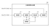
- FIG. 2 is a diagram illustrating a configuration of a traffic index calculation device according to an embodiment of the present disclosure.
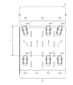
- FIG. 3 is a diagram illustrating an example of a method for calculating traffic information by an acquisition unit in the traffic index calculation device according to the embodiment of the present disclosure.
- FIG. 4 is a diagram illustrating an example of a split calculated by a calculation unit in the traffic index calculation device according to the embodiment of the present disclosure.
- FIG. 5 is a flowchart defining an example of an operation procedure when the traffic index calculation device according to the embodiment of the present disclosure controls a traffic signal.
- the present disclosure has been made to solve the above-mentioned problems, and its purpose is to provide a traffic index calculation device, a traffic index calculation method, and a traffic index calculation program that are capable of controlling traffic signals more appropriately in accordance with the traffic conditions at an intersection.
- traffic signals can be controlled more appropriately according to traffic conditions at an intersection.
- a traffic index calculation device includes an acquisition unit that acquires traffic information related to traffic conditions at an intersection for a vehicle entering the intersection from an entrance road, and an index calculation unit that calculates a directional traffic index, which is a traffic index for at least one traveling direction at the intersection, based on the traffic information acquired by the acquisition unit.
- the acquisition unit may acquire, as the traffic information, a branching rate that is a ratio of the number of vehicles in each of the travel directions to the number of vehicles flowing into the intersection from the entrance road, and the index calculation unit may calculate an entrance road traffic index that is a traffic index for the entrance road, and calculate the directional traffic index that is a traffic index for each of the travel directions based on the calculated entrance road traffic index and the branching rate.
- the incoming road traffic index can be allocated for each direction of travel according to the branching rate, making it possible to calculate more accurate traffic indexes by direction.
- the acquisition unit may acquire, as the traffic information, a green time rate, which is a ratio of the green time for each traveling direction to the green time for the incoming road, and the index calculation unit may calculate an incoming road traffic index, which is a traffic index for the incoming road, and calculate the directional traffic index, which is a traffic index for each traveling direction, based on the calculated incoming road traffic index and the green time rate.
- the incoming road traffic index can be allocated to each direction of travel according to the green time rate, making it possible to calculate more accurate traffic indexes by direction. Also, in cases where the branching rate cannot be obtained, the green time rate, which is easier to obtain than the branching rate, can be used to calculate the traffic index by direction.
- the index calculation unit may calculate the incoming road traffic index based on probe information indicating measurement results related to vehicle travel.
- This configuration makes it possible to calculate the oncoming road traffic index without using the detection results from vehicle detectors, so that traffic signals can be controlled more appropriately according to the traffic conditions at intersections where vehicle detectors are not installed.
- the index calculation unit may calculate a delay time per vehicle due to waiting at a traffic light based on the probe information, and calculate the incoming road traffic index based on the calculated delay time.
- the delay time can be used to calculate the load factor of the approach road as an approach road traffic index.
- the acquisition unit may acquire, as the traffic information, a direction-specific travel time that is a travel time for each of the traveling directions of a vehicle entering the intersection from the entrance road, and the index calculation unit may calculate the direction-specific traffic index that is a traffic index for each of the traveling directions based on the direction-specific travel time.
- This configuration makes it possible to calculate more accurate traffic indicators by direction compared to using branching rates and green time rates.
- the traffic index calculation device may further include a split calculation unit that calculates a split for each traveling direction based on the direction-specific traffic index calculated by the index calculation unit.
- This configuration makes it possible to calculate more appropriate splits according to traffic demand by direction.
- the traffic index calculation device may further include a control unit that controls a traffic signal at the intersection based on the split calculated by the split calculation unit.
- This configuration allows traffic signals to be controlled according to traffic demand in each direction.
- a traffic index calculation method is a traffic index calculation method in a traffic index calculation device, and includes the steps of acquiring traffic information on traffic conditions at an intersection for a vehicle entering the intersection from an entrance road, and calculating a directional traffic index, which is a traffic index for at least one traveling direction at the intersection, based on the acquired traffic information.
- a traffic index calculation program is a traffic index calculation program used in a traffic index calculation device, and is a program for causing a computer to function as an acquisition unit that acquires traffic information related to traffic conditions at an intersection for vehicles entering the intersection from an entrance road, and an index calculation unit that calculates a directional traffic index, which is a traffic index for at least one traveling direction at the intersection, based on the traffic information acquired by the acquisition unit.
- Fig. 1 is a diagram showing a configuration of a traffic signal control system according to an embodiment of the present disclosure.
- a traffic signal control system 201 includes a vehicle 1A and a traffic index calculation device 101.
- Vehicles 1A and 1B travel on a road 41.
- Vehicle 1A is a vehicle 1 that includes an on-board device 2.
- Vehicle 1B is a vehicle 1 that does not include an on-board device 2.
- vehicle 1 must travel on the right side of road 41. That is, road 41 is a right-hand traffic road. Note that road 41 may also be a left-hand traffic road.
- the road 41 includes an intersection 31 and entrance roads 51A, 51B, 51C, and 51D that are entrance roads 51 to the intersection 31.
- a traffic signal 21 is provided at each entrance road 51 at the intersection 31.
- the on-board device 2 in the vehicle 1A is capable of communicating with the traffic index calculation device 101 via the wireless base station 111 and the network 121.
- the on-board device 2 generates probe information indicating measurement results related to the traveling of the vehicle 1A equipped with the on-board device 2, and transmits the generated probe information to the traffic index calculation device 101 via the wireless base station 111 and the network 121.
- the in-vehicle device 2 receives GPS signals from multiple GPS (Global Positioning System) satellites and detects the current position of vehicle 1A and the speed of vehicle 1 based on the received GPS signals.
- the in-vehicle device 2 detects the current position of vehicle 1 and the speed of vehicle 1A at a timing according to a predetermined detection period and stores the detection results and vehicle data indicating the detection time in a storage unit (not shown).
- the in-vehicle device 2 periodically or irregularly acquires multiple vehicle data from the storage unit, generates probe information including the acquired multiple vehicle data and the ID of the in-vehicle device 2, and transmits the generated probe information to the traffic index calculation device 101 via the wireless base station 111 and the network 121.
- the traffic index calculation device 101 calculates a directional traffic index, which is a traffic index for each traveling direction of the vehicle 1 at the intersection 31.
- the traffic index calculation device 101 calculates the split of the intersection 31 based on the calculated directional traffic index.
- split refers to the proportion of time each aspect occupies in one signal period.
- split refers to the ratio of the length of time allocated to each aspect to the cycle length C.
- Split is generally expressed as a percentage or ratio.
- Cycle length C refers to the time required for one cycle of the traffic signal 21 to go around.
- the cycle length C of a traffic signal 21 is the time from when the traffic signal 21 starts to light green to when the next green light starts.
- the cycle length C of a traffic signal 21 may also be the time from when the traffic signal 21 starts to light red to when the next red light starts.
- the traffic index calculation device 101 includes a receiving unit 11, an acquiring unit 12, and a calculating unit 13.
- the receiver 11, the acquirer 12, the calculator 13, and the controller 14 are connected to a storage unit 15.
- the calculator 13 is an example of an index calculator and an example of a split calculator.
- a part or the whole of the unit 14 is realized by, for example, a processing circuit including one or more processors.
- the storage unit 15 is, for example, a non-volatile memory included in the processing circuit.
- the receiving unit 11 acquires traffic light information indicating a cycle length C, a green time G, and a red time R of a traffic light 21.
- the cycle length C is equal to the sum of the red time R and the green time G.
- green time refers to the time period during which vehicle 1 has the right of way at intersection 31.
- Green time G includes straight-ahead right-turn green time G1, which is the time period during which vehicle 1 going straight and vehicle 1 turning right have the right of way at intersection 31, and left-turn green time G2, which is the time period during which vehicle 1 turning left at intersection 31 has the right of way.
- green time G is the green time for the entire oncoming road 51.
- green time G is made up of left-turn green time G2 and straight-ahead right-turn green time G1 following left-turn green time G2.
- the start of left-turn green time G2 is when the green arrow light for left turns is turned on, and the end of left-turn green time G2 is when the green arrow light for left turns is turned off.
- the start of straight-ahead right-turn green time G1 is when the green light is turned on, and the end of straight-ahead right-turn green time G1 is when the green light is turned off.
- the end of the straight-ahead right-turn green time G1 may also be when the yellow light is turned off.
- red time refers to a time period during which vehicle 1 does not have the right of way at intersection 31.
- the start of red time R is when the green light is turned off, and the end of red time R is when the green arrow light for a left turn is turned on. Note that the start of red time R may also be when the yellow light is turned off.
- the receiving unit 11 receives traffic light information of the traffic light 21 from a control device (not shown) in a traffic control center via the network 121.
- the receiving unit 11 stores the received traffic light information in the storage unit 15.
- the receiver 11 also acquires probe information that indicates measurement results related to the traveling of the vehicle 1A. More specifically, the receiver 11 receives the probe information from the in-vehicle device 2 via the wireless base station 111 and the network 121. The receiver 11 stores the received probe information in the memory unit 15.
- the acquisition unit 12 acquires traffic information regarding traffic conditions at the intersection 31 for the vehicle 1A entering the intersection 31 from the entering road 51. For example, the acquisition unit 12 acquires traffic information regarding traffic conditions at the intersection 31 for each traveling direction.
- Travel time by direction TtN The acquisition unit 12 acquires, as traffic information, direction-specific travel times TtN [seconds] which are travel times for each traveling direction of the vehicle 1A entering the intersection 31 from the entering road 51.
- the acquisition unit 12 acquires from the storage unit 15, at a processing timing according to a predetermined processing cycle Cy, a plurality of pieces of probe information received by the receiving unit 11 during the period from the previous processing timing to the current processing timing.
- the acquisition unit 12 calculates the direction-specific travel time TtN based on the acquired plurality of pieces of probe information.
- the processing cycle Cy may be the same length as the cycle length C of the traffic signal 21, or may be a predetermined length different from the cycle length C.
- FIG. 3 is a diagram showing an example of a method for calculating traffic information by an acquisition unit in a traffic index calculation device according to an embodiment of the present disclosure.
- the entrance road 51 includes a lane CL1 for going straight, a lane CL2 for turning right, and a lane CL3 for turning left.
- the acquisition unit 12 calculates the direction-specific travel times Tt1, Tt2, and Tt3, which are the direction-specific travel times TtN for the driving section S of a predetermined length L to the intersection 31 on the entrance road 51, based on the detection results of the positions of the multiple vehicles 1A indicated by the multiple probe information.
- the direction-specific travel time Tt1 is the average travel time when multiple vehicles 1A traveling straight through the intersection 31 travel along the travel section S. In other words, the direction-specific travel time Tt1 is the average travel time when multiple vehicles 1A travel along the travel section S in the lane CL1.
- the direction-specific travel time Tt2 is the average travel time when multiple vehicles 1A turning right at the intersection 31 travel along the travel section S. In other words, the direction-specific travel time Tt2 is the average travel time when multiple vehicles 1A travel along the travel section S on the lane CL2.
- the direction-specific travel time Tt3 is the average travel time when multiple vehicles 1A turning left at the intersection 31 travel along the travel section S. In other words, the direction-specific travel time Tt3 is the average travel time when multiple vehicles 1A travel along the travel section S on the lane CL3.
- the acquisition unit 12 calculates the direction-specific travel times Tt1, Tt2, and Tt3 for each entrance road 51, and outputs the calculated direction-specific travel times Tt1, Tt2, and Tt3 to the calculation unit 13.
- Branching rate RtN The acquisition unit 12 acquires, as traffic information, a branching rate RtN, which is a ratio of the number of vehicles 1A in each traveling direction to the number of vehicles 1A entering the intersection 31 from the entering road 51.
- the acquisition unit 12 calculates the average travel time Tt [seconds] of the vehicle 1A entering the intersection 31 from the entrance road 51 and the branch rate RtN based on the multiple pieces of probe information acquired from the memory unit 15.
- the acquisition unit 12 calculates the average travel time Tt for the driving section S on the entire entrance road 51 based on the detection results of the positions of the multiple vehicles 1A indicated by the multiple pieces of probe information.
- the average travel time Tt is the average travel time when the multiple vehicles 1A traveling in each direction at the intersection 31 travel the driving section S on the entrance road 51.
- the acquisition unit 12 also calculates branch rates Rt1, Rt2, and Rt3, which are the branch rate RtN, based on the detection results of the positions of the multiple vehicles 1A indicated by the multiple probe information.
- the branch rate Rt1 is the ratio of the number of vehicles 1A going straight at the intersection 31 to the number of vehicles 1A entering the intersection 31 from the entrance road 51.
- the branch rate Rt2 is the ratio of the number of vehicles 1A turning right at the intersection 31 to the number of vehicles 1A entering the intersection 31 from the entrance road 51.
- the branch rate Rt3 is the ratio of the number of vehicles 1A turning left at the intersection 31 to the number of vehicles 1A entering the intersection 31 from the entrance road 51.
- the acquisition unit 12 calculates the branching rates Rt1, Rt2, Rt3 and the average travel time Tt for each inflow path 51, and outputs the calculated branching rates Rt1, Rt2, Rt3 and the average travel time Tt to the calculation unit 13.
- the intersection 31 includes vehicle 1B that does not transmit probe information.
- the proportion of vehicles 1A in the total number of vehicles 1 has been increasing, so the branching rate RtN calculated based on the probe information can be considered as the proportion of the number of vehicles 1 in each direction of travel to the total number of vehicles 1 entering the intersection 31 from the entrance road 51.
- Green time rate GrN The acquisition unit 12 acquires, as traffic information, a green time rate GrN, which is the ratio of the green time to the green time G of the entering road 51 for each traveling direction.
- the acquisition unit 12 acquires traffic light information from the storage unit 15, and calculates the green time rates GrX, GrY, which are the green time rate GrN, based on the received traffic light information.
- the green time rate GrX is the ratio of the straight-through right-turn green time G1 to the green time G.
- the green time rate GrY is the ratio of the left-turn green time G2 to the green time G.
- the acquisition unit 12 calculates the green time rates GrX, GrY for each incoming road 51, and stores the calculated green time rates GrX, GrY in the storage unit 15.
- the acquisition unit 12 when the number of pieces of probe information acquired from the memory unit 15 is small, the acquisition unit 12 is unable to calculate the direction-specific travel time TtN and branching rate RtN, or is unable to calculate sufficiently accurate direction-specific travel time TtN and branching rate RtN. In this case, the acquisition unit 12 calculates the average travel time Tt for each entrance road 51 based on the multiple pieces of probe information acquired from the memory unit 15.
- the acquisition unit 12 also acquires the green time rate GrN from the memory unit 15, and outputs the acquired green time rate GrN and the calculated average travel time Tt to the calculation unit 13.
- the calculation unit 13 calculates a load factor LrN, which is a load factor of at least one traveling direction at the intersection 31, as a direction-specific traffic index based on the traffic information acquired by the acquisition unit 12. For example, the calculation unit 13 calculates the load factor LrN for each traveling direction.
- the load factor is the ratio of traffic demand to the maximum traffic volume that can be handled in one cycle.
- the load factor LrN is an example of a direction-specific traffic index.
- the calculation unit 13 calculates a split for each traveling direction based on the calculated load factor LrN.
- the load factor Lr which is the load factor of the entire entering road 51, is expressed by the following formula (1) using the traffic volume Vin [vehicles/sec], the number of queued vehicles Qin [vehicles/sec] converted to traffic volume, and the saturation traffic flow rate Sf [vehicles/sec], as well as a predetermined weighting coefficient k.
- the delay time dav is a value obtained by subtracting the travel time [seconds] when the vehicle 1A travels the traveling section S without waiting at traffic lights from the average travel time Tt when the vehicle 1A travels the traveling section S.
- the saturation traffic flow rate Sf is expressed as the flow rate at which the second or third or subsequent vehicles pass the stop line after the traffic signal 21 turns green when there is a sufficiently long queue at the entrance to the intersection 31.
- the saturation traffic flow rate Sf is the maximum number of vehicles that can pass the stop line per lane per unit time at the entrance to the intersection 31 when there is sufficient traffic demand.
- the value of the saturation traffic flow rate Sf differs depending on the presence or absence of a dedicated right-turn lane, the presence or absence of a dedicated left-turn lane, the lane width, etc.
- the saturation flow rate Sf is offset by the numerator and denominator on the right-hand side of equation (1). Therefore, the load rate Lr can be calculated using the delay time dav, and the cycle length C and red time R indicated by the traffic light information.
- the calculation unit 13 calculates the load factor LrN based on the direction-specific travel time TtN. More specifically, when the calculation unit 13 receives the direction-specific travel times Tt1, Tt2, and Tt3 from the acquisition unit 12, the calculation unit 13 calculates the delay times dav1, dav2, and dav3, which are the direction-specific delay times dav, by substituting the received direction-specific travel times Tt1, Tt2, and Tt3 into the average travel time Tt in the above-mentioned formula (4).
- the delay time dav1 is the delay time dav of vehicle 1A traveling in lane CL1 for going straight.
- the delay time dav2 is the delay time dav of vehicle 1A traveling in lane CL2 for turning right.
- the delay time dav3 is the delay time dav of vehicle 1A traveling in lane CL3 for turning left.
- the calculation unit 13 substitutes the calculated delay times dav1, dav2, dav3, as well as the cycle length C and red time R indicated by the traffic light information in the memory unit 15 into the above-mentioned formula (3), to calculate the queue numbers Qin1, Qin2, Qin3, which are the queue numbers Qin for each direction expressed using the unknown saturation flow rate Sf.
- Qin1 is the number of queuing vehicles Qin in the straight-through lane CL1.
- Qin2 is the number of queuing vehicles Qin in the right-turn lane CL2.
- Qin3 is the number of queuing vehicles Qin in the left-turn lane CL3.
- the calculation unit 13 also calculates the traffic volume Vin expressed using the unknown saturation traffic flow rate Sf according to the above-mentioned formula (2) based on the traffic light information in the memory unit 15.
- the calculation unit 13 calculates the load factors Lr1, Lr2, and Lr3, which are the load factor LrN, by substituting the calculated traffic volume Vin and the calculated queued vehicle numbers Qin1, Qin2, and Qin3 into the above-mentioned formula (1).
- Load rate Lr1 is the load rate Lr in the straight-through lane CL1.
- Load rate Lr2 is the load rate Lr in the right-turn lane CL2.
- Load rate Lr3 is the load rate Lr in the left-turn lane CL3.
- the calculation unit 13 calculates the load rates Lr1, Lr2, and Lr3 for each entrance road 51.
- the calculation unit 13 calculates the load rate Lr, which is a traffic index of the inflow road 51, and calculates the load rate LrN based on the calculated load rate Lr and the branching rate RtN.
- the calculation unit 13 calculates the load factor Lr based on the probe information. For example, the calculation unit 13 calculates the delay time dav based on the probe information, and calculates the load factor Lr based on the calculated delay time dav.
- the calculation unit 13 receives the branch rates Rt1, Rt2, Rt3 and the average travel time Tt from the acquisition unit 12, it calculates the delay time dav by substituting the received average travel time Tt into the above-mentioned formula (4).
- the calculation unit 13 substitutes the calculated delay time dav, as well as the cycle length C and red time R indicated by the traffic light information in the memory unit 15, into the above-mentioned formula (3) to calculate the number of queued vehicles Qin, which is expressed using the unknown saturation traffic flow rate Sf.
- the calculation unit 13 also calculates the traffic volume Vin expressed using the unknown saturation traffic flow rate Sf according to the above-mentioned formula (2) based on the traffic light information in the memory unit 15.
- the calculation unit 13 calculates the load factor Lr by substituting the calculated traffic volume Vin and the calculated number of queued vehicles Qin into the above-mentioned formula (1).
- the calculation unit 13 uses the calculated load factor Lr and the branching rates Rt1, Rt2, and Rt3 received from the acquisition unit 12 to calculate the load factors Lr1, Lr2, and Lr3, which are the load factors for each direction, according to the following equations (5) to (7).
- Lr1 Lr ⁇ Rt1/(Rt2+Rt3) ⁇ (Ln2+Ln3)/Ln1 ⁇ ...
- Lr2 Lr ⁇ Rt2/(Rt1+Rt3) ⁇ (Ln1+Ln3)/Ln2 ⁇ ...
- Lr3 Lr ⁇ Rt3/(Rt1+Rt2) ⁇ (Ln1+Ln2)/Ln3 ⁇ ...(7)
- Ln1 is the number of lanes in the straight-through lane CL1.
- Ln2 is the number of lanes in the right-turn lane CL2.
- Ln3 is the number of lanes in the left-turn lane CL3.
- the calculation unit 13 calculates the load factors Lr1, Lr2, and Lr3 for each entrance road 51.
- the calculation unit 13 calculates the load factor Lr, which is a traffic index for the entering road 51, and calculates the load factor LrN based on the calculated load factor Lr and the green time rate GrN.
- the calculation unit 13 receives the green time rate GrN and the average travel time Tt from the acquisition unit 12, it calculates the delay time dav by substituting the received average travel time Tt into the above-mentioned formula (4).
- the calculation unit 13 substitutes the calculated delay time dav, as well as the cycle length C and red time R indicated by the traffic light information in the memory unit 15, into the above-mentioned formula (3) to calculate the number of queued vehicles Qin, which is expressed using the unknown saturation traffic flow rate Sf.
- the calculation unit 13 also calculates the traffic volume Vin expressed using the unknown saturation traffic flow rate Sf according to the above-mentioned formula (2) based on the traffic light information in the memory unit 15.
- the calculation unit 13 calculates the load factor Lr by substituting the calculated traffic volume Vin and the calculated number of queued vehicles Qin into the above-mentioned formula (1).
- the calculation unit 13 uses the calculated load factor Lr and the green time rate GrN received from the acquisition unit 12 to calculate the load factors Lr1, Lr2, and Lr3, respectively, in accordance with the following equations (8) to (10).
- Lr1 Lr ⁇ (GrY/GrX) ⁇ (Ln2+Ln3)/Ln1 ⁇ ...
- Lr2 Lr ⁇ (GrY/GrX) ⁇ (Ln1+Ln3)/Ln2 ⁇ ...(9)
- Lr3 Lr ⁇ (GrX/GrY) ⁇ (Ln1+Ln2)/Ln3 ⁇ ...(10)
- the calculation unit 13 calculates the load factors Lr1, Lr2, and Lr3 for each inflow passage 51.
- the load factors Lr1, Lr2, and Lr3 of the inflow passage 51A will also be referred to as load factors Lr1A, Lr2A, and Lr3A
- the load factors Lr1, Lr2, and Lr3 of the inflow passage 51B will also be referred to as load factors Lr1B, Lr2B, and Lr3B
- the load factors Lr1, Lr2, and Lr3 of the inflow passage 51C will also be referred to as load factors Lr1C, Lr2C, and Lr3C
- the load factors Lr1, Lr2, and Lr3 of the inflow passage 51D will also be referred to as load factors Lr1D, Lr2D, and Lr3D.
- FIG. 4 is a diagram showing an example of a split calculated by a calculation unit in the traffic index calculation device according to the embodiment of the present disclosure.
- Fig. 4 shows a current stage diagram of rings Ra and Rb at an intersection 31 of a dual ring system.
- ring Ra includes aspects Ra1, Ra2, Ra3, and Ra4.
- Ring Rb includes aspects Rb1, Rb2, Rb3, and Rb4.
- Aspect Ra1 is the time period during which the right of way is assigned to vehicle 1 entering the intersection 31 from the entrance road 51C and turning left.
- Aspect Ra2 is the time period during which the right of way is assigned to vehicle 1 entering the intersection 31 from the entrance road 51A and going straight or turning right.
- Aspect Ra3 is the time period during which the right of way is assigned to vehicle 1 entering the intersection 31 from the entrance road 51D and turning left.
- Aspect Ra4 is the time period during which the right of way is assigned to vehicle 1 entering the intersection 31 from the entrance road 51B and going straight or turning right.
- Aspect Rb1 is the time period during which the right of way is assigned to vehicle 1 entering the intersection 31 from the entrance road 51A and turning left.
- Aspect Rb2 is the time period during which the right of way is assigned to vehicle 1 entering the intersection 31 from the entrance road 51C and going straight or turning right.
- Aspect Rb3 is the time period during which the right of way is assigned to vehicle 1 entering the intersection 31 from the entrance road 51B and turning left.
- Aspect Rb4 is the time period during which the right of way is assigned to vehicle 1 entering the intersection 31 from the entrance road 51D and going straight or turning right.
- the calculation unit 13 calculates the load factors Lr1, Lr2, and Lr3 for each inflow passage 51, and then calculates the load factor LrAC, which is the load factor for the inflow passages 51A and 51C, and the load factor LrBD, which is the load factor for the inflow passages 51B and 51D, based on the calculated load factors Lr1, Lr2, and Lr3.
- the calculation unit 13 calculates the load factors LrAC and LrBD using the load factors Lr1, Lr2, and Lr3 for each inflow passage 51 according to the following equations (11) and (12).
- LrAC Max ⁇ Lr3C+Lr1A+Lr2A, Lr3A+Lr1C+Lr2C ⁇ ...(11)
- LrBD Max ⁇ Lr3D+Lr1B+Lr2B, Lr3B+Lr1D+Lr2D ⁇ ...(12)
- the calculation unit 13 uses the calculated load factors LrAC, LrBD to calculate the split Sp1 of the inflow paths 51A, 51C and the split Sp2 of the inflow paths 51B, 51D in accordance with the following equations (13) and (14).
- Sp1 LrAC/(LrAC+LrBD)...(13)
- Sp2 LrBD/(LrAC+LrBD)...(14)
- the calculation unit 13 uses the split Sp1 to calculate the split Spa1 of the current indication Ra1, the split Spa2 of the current indication Ra2, the split Spb1 of the current indication Rb1, and the split Spb2 of the current indication Rb2 in accordance with the following equations (15) to (18).
- the calculation unit 13 uses the split Sp2 to calculate a split Spa3 of the current indication Ra3, a split Spa4 of the current indication Ra4, a split Spb3 of the current indication Rb3, and a split Spb4 of the current indication Rb4 in accordance with the following equations (19) to (22).
- Spa3 Sp2 ⁇ Lr3D/(Lr3D+Lr1B+Lr2B).
- Spa4 Sp2 ⁇ (Lr1B+Lr2B)/(Lr3D+Lr1B+Lr2B).
- Spb3 Sp2 ⁇ Lr3B/(Lr3B+Lr1D+Lr2D).
- Spb4 Sp2 ⁇ (Lr1D+Lr2D)/(Lr3B+Lr1D+Lr2D)...(22)
- the calculation unit 13 outputs the calculated splits Spa1, Spa2, Spa3, Spa4, Spb1, Spb2, Spb3, and Spb4 to the control unit 14.
- each of the splits Spa1, Spa2, Spa3, Spa4, Spb1, Spb2, Spb3, and Spb4 will also be referred to as a split SpN.
- Control Unit 14 controls the traffic signal 21 at the intersection 31 based on the split SpN calculated by the calculation unit 13 .
- control unit 14 receives the split SpN from the calculation unit 13 and transmits a signal control instruction including the received split SpN to a control device (not shown) that controls the traffic signal 21 via the network 121.
- the control device receives the signal control instruction from the traffic index calculation device 101, and controls the traffic signal 21 based on the split SpN included in the received signal control instruction.
- FIG. 5 is a flowchart defining an example of an operation procedure when the traffic index calculation device according to the embodiment of the present disclosure controls a traffic signal.
- the traffic index calculation device 101 waits for the processing timing according to the processing cycle Cy (NO in step S11), and when the processing timing arrives (YES in step S11), it acquires from the memory unit 15 a number of pieces of probe information received from the vehicle 1A during the period from the previous processing timing to the current processing timing (step S12).
- the traffic index calculation device 101 calculates the direction-specific travel time TtN based on the probe information (YES in step S13). It calculates the direction-specific travel time TtN (step S14).
- the traffic index calculation device 101 calculates the load factor LrN based on the calculated direction-specific travel time TtN (step S15).
- the traffic index calculation device 101 calculates the branching rate RtN and the average travel time Tt (step S18).
- the traffic index calculation device 101 calculates the load factor Lr of the inlet road 51 based on the probe information (step S19).
- the traffic index calculation device 101 calculates the load factor LrN based on the load factor Lr, the branch rate RtN, and the average travel time Tt (step S20).
- the traffic index calculation device 101 calculates the average travel time Tt (step S21).
- the traffic index calculation device 101 calculates the load factor Lr of the inflow road 51 based on the probe information (step S22).
- the traffic index calculation device 101 calculates the load factor LrN based on the load factor LrN, the green light ratio GrtN, and the average travel time Tt (step S23).
- the traffic index calculation device 101 calculates the split SpN for each travel direction based on the load factor LrN calculated for each entrance road 51 (step S24).
- the traffic index calculation device 101 controls the traffic signal 21 at the intersection 31 based on the split SpN (step S25).
- the traffic index calculation device 101 waits for a new processing timing according to the processing cycle Cy (NO in step S11).
- the acquisition unit 12 is configured to acquire traffic information related to traffic conditions for each traveling direction at the intersection 31, but this is not limited to this.
- the acquisition unit 12 may also be configured to acquire traffic information related to traffic conditions in any one traveling direction at the intersection 31.
- the calculation unit 13 is configured to calculate the load factor LrN for each traveling direction, but this is not limited to this.
- the calculation unit 13 may be configured to calculate the load factor LrN for any one of the traveling directions at the intersection 31.
- the calculation unit 13 is configured to calculate the load factor LrN as a traffic index by direction, but this is not limited thereto.
- the calculation unit 13 may be configured to calculate the current saturation degree DsN, which is the current saturation degree for each traveling direction, instead of or in addition to the load factor LrN.
- the current saturation degree is the ratio of the arriving traffic volume to the maximum traffic volume that can be processed during the green time G.
- the arriving traffic volume is the number of vehicles 1 arriving at the stop line of the entering road 51.
- the current saturation degree Ds which is the current saturation degree of the entire entering road 51, is expressed by the following formula (23).
- the calculation unit 13 calculates the current saturation degree DsN for each inflow passage 51, and calculates the split SpN according to the above-mentioned formulas (11) to (22) using the current saturation degree DsN instead of the load factor LrN.
- the acquisition unit 12 is configured to be able to acquire the direction-specific travel time TtN, the branch rate RtN, and the green time rate GrN as traffic information, but this is not limited to this.
- the acquisition unit 12 may be configured not to have the function of acquiring any one or two of the direction-specific travel time TtN, the branch rate RtN, and the green time rate GrN.
- the calculation unit 13 is configured to calculate the load rate Lr based on probe information, but this is not limited to this.
- the calculation unit 13 may be configured to calculate the traffic volume Vin, the number of queuing vehicles Qin, and the saturation traffic flow rate Sf based on the detection results of a vehicle detector installed at an intersection instead of the probe information, and to calculate the load rate Lr based on the calculated traffic volume Vin, the number of queuing vehicles Qin, and the saturation traffic flow rate Sf.
- the calculation unit 13 is configured to calculate the delay time dav based on the probe information, and to calculate the load factor Lr based on the calculated delay time dav, but this is not limited to this.
- the calculation unit 13 may be configured to calculate the load factor Lr by some method without using the delay time dav.
- the calculation unit 13 is configured to calculate the split SpN based on the load factor LrN, but this is not limited to the above.
- the calculation unit 13 may be configured to calculate the load factor LrN but not calculate the split SpN. In this case, the calculation unit 13 transmits the calculated load factor LrN to a device external to the traffic index calculation device 101.
- the traffic index calculation device 101 is configured to include a control unit 14, this is not limited to this.
- the traffic index calculation device 101 may be configured not to include a control unit 14. In this case, the calculation unit 13 transmits the calculated split SpN to a device outside the traffic index calculation device 101.
- the receiver 11 is configured to receive probe information from the in-vehicle device 2, but this is not limited to the above.
- the receiver 11 may be configured to receive probe information from a communication device such as a smartphone in the vehicle 1 instead of the in-vehicle device 2.
- Each process (each function) in the above-mentioned embodiments is realized by a processing circuit (circuitry) including one or more processors.
- the above-mentioned processing circuit may be composed of an integrated circuit or the like that combines one or more memories, various analog circuits, and various digital circuits in addition to the one or more processors.
- the one or more memories store programs (instructions) that cause the one or more processors to execute each of the above processes.
- the one or more processors may execute each of the above processes according to the programs read from the one or more memories, or may execute each of the above processes according to a logic circuit designed in advance to execute each of the above processes.
- the processor may be any of various processors suitable for computer control, such as a CPU (Central Processing Unit), a GPU (Graphics Processing Unit), a DSP (Digital Signal Processor), an FPGA (Field Programmable Gate Array), and an ASIC (Application Specific Integrated Circuit).
- the physically separated processors may cooperate with each other to execute the above processes.
- the processors mounted on each of the physically separated computers may cooperate with each other via a network such as a LAN (Local Area Network), a WAN (Wide Area Network), or the Internet to execute the above processes.
- the above program may be installed into the memory from an external server device or the like via the network, or may be distributed in a state stored on a recording medium such as a CD-ROM (Compact Disc Read Only Memory), DVD-ROM (Digital Versatile Disc Read Only Memory), or semiconductor memory, and installed into the memory from the recording medium.
- a recording medium such as a CD-ROM (Compact Disc Read Only Memory), DVD-ROM (Digital Versatile Disc Read Only Memory), or semiconductor memory, and installed into the memory from the recording medium.
- a traffic index calculation device A processing circuit is provided, The processing circuitry includes: Acquire traffic information regarding a traffic situation at an intersection for a vehicle entering the intersection from an entrance road; A traffic index calculation device that calculates a direction-specific traffic index, which is a traffic index for at least one traveling direction at the intersection, based on the acquired traffic information.
Landscapes
- Engineering & Computer Science (AREA)
- Computing Systems (AREA)
- Physics & Mathematics (AREA)
- General Physics & Mathematics (AREA)
- Operations Research (AREA)
- Business, Economics & Management (AREA)
- Accounting & Taxation (AREA)
- Development Economics (AREA)
- Economics (AREA)
- General Business, Economics & Management (AREA)
- Traffic Control Systems (AREA)
Abstract
交通指標算出装置は、流入路から交差点へ流入する車両の、前記交差点における交通状況に関する交通情報を取得する取得部と、前記取得部により取得された前記交通情報に基づいて、前記交差点における少なくともいずれか1つの進行方向の交通指標である方向別交通指標を算出する指標算出部とを備える。
Description
本開示は、交通指標算出装置、交通指標算出方法および交通指標算出プログラムに関する。
この出願は、2023年6月14日に出願された日本出願特願2023-97394号を基礎とする優先権を主張し、その開示のすべてをここに取り込む。
この出願は、2023年6月14日に出願された日本出願特願2023-97394号を基礎とする優先権を主張し、その開示のすべてをここに取り込む。
特許文献1(国際公開第2020/071040号)には、以下のような算出装置が記載されている。すなわち、算出装置は、信号制御パラメータの算出に必要となる交通指標を算出する装置であって、対象交差点の流入路の交通変数を飽和交通流率に対する比率で表した正規化データを算出する第1算出部と、前記正規化データを用いて、前記流入路の交通変数が分子に含まれ前記飽和交通流率が分母に含まれる式で定義される前記交通指標を算出する第2算出部とを備える。
本開示の交通指標算出装置は、流入路から交差点へ流入する車両の、前記交差点における交通状況に関する交通情報を取得する取得部と、前記取得部により取得された前記交通情報に基づいて、前記交差点における少なくともいずれか1つの進行方向の交通指標である方向別交通指標を算出する指標算出部とを備える。
本開示の一態様は、このような特徴的な処理部を備える交通指標算出装置として実現され得るだけでなく、交通指標算出装置の一部または全部を実現する半導体集積回路として実現され得たり、交通指標算出装置を含む交通信号制御システムとして実現され得る。
交差点に設けられた交通信号機の遠隔制御に用いられる信号制御パラメータを算出する技術が開発されている。
[本開示が解決しようとする課題]
特許文献1に記載の技術を超えて、交差点における交通状況に応じてより適切に交通信号機を制御することが可能な技術が望まれる。
特許文献1に記載の技術を超えて、交差点における交通状況に応じてより適切に交通信号機を制御することが可能な技術が望まれる。
本開示は、上述の課題を解決するためになされたもので、その目的は、交差点における交通状況に応じてより適切に交通信号機を制御することが可能な交通指標算出装置、交通指標算出方法および交通指標算出プログラムを提供することである。
[本開示の効果]
本開示によれば、交差点における交通状況に応じてより適切に交通信号機を制御することができる。
本開示によれば、交差点における交通状況に応じてより適切に交通信号機を制御することができる。
[本開示の実施形態の説明]
最初に、本開示の実施形態の内容を列記して説明する。
最初に、本開示の実施形態の内容を列記して説明する。
(1)本開示の実施の形態に係る交通指標算出装置は、流入路から交差点へ流入する車両の、前記交差点における交通状況に関する交通情報を取得する取得部と、前記取得部により取得された前記交通情報に基づいて、前記交差点における少なくともいずれか1つの進行方向の交通指標である方向別交通指標を算出する指標算出部とを備える。
このように、交差点における交通状況に関する交通情報に基づいて、交差点における進行方向の方向別交通指標を算出する構成により、たとえば、方向別交通指標に基づいて算出した信号制御パラメータを用いて交通信号機を制御することができるので、流入路の交通指標に基づいて算出した信号制御パラメータを用いて交通信号機を制御する構成と比べて、方向別の交通需要に応じて交通信号機を制御することができる。したがって、交差点における交通状況に応じてより適切に交通信号機を制御することができる。
(2)上記(1)において、前記取得部は、前記交通情報として、前記流入路から前記交差点へ流入する車両の台数に対する前記進行方向ごとの車両の台数の割合である分岐率を取得してもよく、前記指標算出部は、前記流入路の交通指標である流入路交通指標を算出し、算出した前記流入路交通指標と、前記分岐率とに基づいて、前記進行方向ごとの交通指標である前記方向別交通指標を算出してもよい。
このような構成により、たとえば、流入路交通指標を分岐率に応じて進行方向ごとに配分することができるため、より正確な方向別交通指標を算出することができる。
(3)上記(1)または(2)において、前記取得部は、前記交通情報として、前記流入路の青時間に対する前記進行方向ごとの青時間の割合である青時間率を取得してもよく、前記指標算出部は、前記流入路の交通指標である流入路交通指標を算出し、算出した前記流入路交通指標と、前記青時間率とに基づいて、前記進行方向ごとの交通指標である前記方向別交通指標を算出してもよい。
このような構成により、たとえば、流入路交通指標を青時間率に応じて進行方向ごとに配分することができるため、より正確な方向別交通指標を算出することができる。また、分岐率が取得できない場合において、分岐率よりも容易に取得可能な青時間率を用いて方向別交通指標を算出することができる。
(4)上記(2)または(3)において、前記指標算出部は、車両の走行に関する計測結果を示すプローブ情報に基づいて、前記流入路交通指標を算出してもよい。
このような構成により、車両感知器による感知結果を用いることなく流入路交通指標を算出することができるので、車両感知器が設置されていない交差点において、交差点における交通状況に応じてより適切に交通信号機を制御することができる。
(5)上記(4)において、前記指標算出部は、前記プローブ情報に基づいて、車両1台当たりの信号待ちによる遅れ時間を算出し、算出した前記遅れ時間に基づいて前記流入路交通指標を算出してもよい。
このような構成により、遅れ時間を用いて、流入路交通指標として流入路の負荷率を算出することができる。
(6)上記(1)から(5)のいずれかにおいて、前記取得部は、前記交通情報として、前記流入路から前記交差点へ流入する車両の前記進行方向ごとの旅行時間である方向別旅行時間を取得してもよく、前記指標算出部は、前記方向別旅行時間に基づいて、前記進行方向ごとの交通指標である前記方向別交通指標を算出してもよい。
このような構成により、分岐率および青時間率を用いる場合と比べて、より正確な方向別交通指標を算出することができる。
(7)上記(1)から(6)のいずれかにおいて、前記交通指標算出装置は、さらに、前記指標算出部により算出された前記方向別交通指標に基づいて、前記進行方向ごとのスプリットを算出するスプリット算出部を備えてもよい。
このような構成により、方向別の交通需要に応じたより適切なスプリットを算出することができる。
(8)上記(7)において、前記交通指標算出装置は、さらに、前記スプリット算出部により算出された前記スプリットに基づいて、前記交差点における交通信号機を制御する制御部を備えてもよい。
このような構成により、方向別の交通需要に応じて交通信号機を制御することができる。
(9)本開示の実施の形態に係る交通指標算出方法は、交通指標算出装置における交通指標算出方法であって、流入路から交差点へ流入する車両の、前記交差点における交通状況に関する交通情報を取得するステップと、取得した前記交通情報に基づいて、前記交差点における少なくともいずれか1つの進行方向の交通指標である方向別交通指標を算出するステップとを含む。
このように、交差点における交通状況に関する交通情報に基づいて、交差点における進行方向の方向別交通指標を算出する方法により、たとえば、方向別交通指標に基づいて算出した信号制御パラメータを用いて交通信号機を制御することができるので、流入路の交通指標に基づいて算出した信号制御パラメータを用いて交通信号機を制御する方法と比べて、方向別の交通需要に応じて交通信号機を制御することができる。したがって、交差点における交通状況に応じてより適切に交通信号機を制御することができる。
(10)本開示の実施の形態に係る交通指標算出プログラムは、交通指標算出装置において用いられる交通指標算出プログラムであって、コンピュータを、流入路から交差点へ流入する車両の、前記交差点における交通状況に関する交通情報を取得する取得部と、前記取得部により取得された前記交通情報に基づいて、前記交差点における少なくともいずれか1つの進行方向の交通指標である方向別交通指標を算出する指標算出部、として機能させるためのプログラムである。
このように、交差点における交通状況に関する交通情報に基づいて、交差点における進行方向の方向別交通指標を算出する構成により、たとえば、方向別交通指標に基づいて算出した信号制御パラメータを用いて交通信号機を制御することができるので、流入路の交通指標に基づいて算出した信号制御パラメータを用いて交通信号機を制御する構成と比べて、方向別の交通需要に応じて交通信号機を制御することができる。したがって、交差点における交通状況に応じてより適切に交通信号機を制御することができる。
以下、本開示の実施の形態について図面を用いて説明する。なお、図中同一または相当部分には同一符号を付してその説明は繰り返さない。また、以下に記載する実施の形態の少なくとも一部を任意に組み合わせてもよい。
[構成および基本動作]
図1は、本開示の実施の形態に係る交通信号制御システムの構成を示す図である。図1を参照して、交通信号制御システム201は、車両1Aと、交通指標算出装置101とを備える。車両1A,1Bは、道路41を走行する。車両1Aは、車載装置2を備える車両1である。車両1Bは、車載装置2を備えない車両1である。図1に示す例では、車両1は、道路41の右側部分を通行しなければならないものとする。すなわち、道路41は、右側通行の道路である。なお、道路41は、左側通行の道路であってもよい。
図1は、本開示の実施の形態に係る交通信号制御システムの構成を示す図である。図1を参照して、交通信号制御システム201は、車両1Aと、交通指標算出装置101とを備える。車両1A,1Bは、道路41を走行する。車両1Aは、車載装置2を備える車両1である。車両1Bは、車載装置2を備えない車両1である。図1に示す例では、車両1は、道路41の右側部分を通行しなければならないものとする。すなわち、道路41は、右側通行の道路である。なお、道路41は、左側通行の道路であってもよい。
道路41は、交差点31と、交差点31の流入路51である流入路51A,51B,51C,51Dとを含む。交差点31には、流入路51ごとに交通信号機21が設けられている。
車両1Aにおける車載装置2は、無線基地局111およびネットワーク121を介して交通指標算出装置101と通信を行うことが可能である。車載装置2は、当該車載装置2を備える車両1Aの走行に関する計測結果を示すプローブ情報を生成し、生成したプローブ情報を無線基地局111およびネットワーク121経由で交通指標算出装置101へ送信する。
より詳細には、車載装置2は、複数のGPS(Global Positioning System)衛星からGPS信号を受信し、受信したGPS信号に基づいて、車両1Aの現在位置および車両1の速度を検出する。車載装置2は、所定の検出周期に従うタイミングにおいて、車両1の現在位置および車両1Aの速度を検出し、検出結果および検出時刻を示す車両データを図示しない記憶部に保存する。車載装置2は、定期的または不定期に、当該記憶部から複数の車両データを取得し、取得した複数の車両データおよび当該車載装置2のIDを含むプローブ情報を生成し、生成したプローブ情報を無線基地局111およびネットワーク121経由で交通指標算出装置101へ送信する。
交通指標算出装置101は、交差点31における車両1の進行方向ごとの交通指標である方向別交通指標を算出する。交通指標算出装置101は、算出した方向別交通指標に基づいて、交差点31のスプリットを算出する。
ここで、「スプリット」は、信号1周期に占める各現示の時間比率である。すなわち、スプリットは、各現示に割り当てられる時間の長さのサイクル長Cに対する割合のことをいう。スプリットは、一般に、百分率あるいは割合で表される。
「サイクル長C」は、交通信号機21の信号表示が一巡する1サイクルの所要時間のことをいう。すなわち、交通信号機21のサイクル長Cは、当該交通信号機21の青点灯の開始時刻から次の青点灯の開始時刻までの時間である。なお、交通信号機21のサイクル長Cは、当該交通信号機21の赤点灯の開始時刻から次の赤点灯の開始時刻までの時間であってもよい。
<交通指標算出装置>
図2は、本開示の実施の形態に係る交通指標算出装置の構成を示す図である。図2を参照して、交通指標算出装置101は、受信部11と、取得部12と、算出部13と、制御部14と、記憶部15とを備える。算出部13は、指標算出部の一例であり、かつスプリット算出部の一例である。受信部11、取得部12、算出部13および制御部14の一部または全部は、たとえば、1または複数のプロセッサを含む処理回路(Circuitry)により実現される。記憶部15は、たとえば上記処理回路に含まれる不揮発性メモリである。
図2は、本開示の実施の形態に係る交通指標算出装置の構成を示す図である。図2を参照して、交通指標算出装置101は、受信部11と、取得部12と、算出部13と、制御部14と、記憶部15とを備える。算出部13は、指標算出部の一例であり、かつスプリット算出部の一例である。受信部11、取得部12、算出部13および制御部14の一部または全部は、たとえば、1または複数のプロセッサを含む処理回路(Circuitry)により実現される。記憶部15は、たとえば上記処理回路に含まれる不揮発性メモリである。
(受信部)
受信部11は、交通信号機21のサイクル長C、青時間Gおよび赤時間Rを示す信号機情報を取得する。サイクル長Cは、赤時間Rと青時間Gとの和に等しい。
受信部11は、交通信号機21のサイクル長C、青時間Gおよび赤時間Rを示す信号機情報を取得する。サイクル長Cは、赤時間Rと青時間Gとの和に等しい。
ここで、「青時間」は、交差点31において車両1に通行権がある時間帯のことをいう。青時間Gは、交差点31において直進する車両1および右折する車両1に通行権がある時間帯である直進右折青時間G1と、交差点31において左折する車両1に通行権がある時間帯である左折青時間G2とを含む。すなわち、青時間Gは、流入路51の全体の青時間である。たとえば、青時間Gは、左折青時間G2と、左折青時間G2に続く直進右折青時間G1とからなる。左折青時間G2の開始時点は、左折用の青矢印灯器の点灯時点であり、左折青時間G2の終了時点は、左折用の青矢印灯器の消灯時点である。直進右折青時間G1の開始時点は、青灯器の点灯時点であり、直進右折青時間G1の終了時点は、青灯器の消灯時点である。なお、直進右折青時間G1の終了時点は、黄灯器の消灯時点であってもよい。
また、「赤時間」は、交差点31において車両1に通行権がない時間帯のことをいう。赤時間Rの開始時点は、青灯器の消灯時点であり、赤時間Rの終了時点は、左折用の青矢印灯器の点灯時点である。なお、赤時間Rの開始時点は、黄灯器の消灯時点であってもよい。
たとえば、受信部11は、交通管制センターにおける図示しない制御装置から、ネットワーク121経由で交通信号機21の信号機情報を受信する。受信部11は、受信した信号機情報を記憶部15に保存する。
また、受信部11は、車両1Aの走行に関する計測結果を示すプローブ情報を取得する。より詳細には、受信部11は、無線基地局111およびネットワーク121経由で車載装置2からプローブ情報を受信する。受信部11は、受信したプローブ情報を記憶部15に保存する。
(取得部)
取得部12は、流入路51から交差点31へ流入する車両1Aの、交差点31における交通状況に関する交通情報を取得する。たとえば、取得部12は、交差点31における進行方向ごとの交通状況に関する交通情報を取得する。
取得部12は、流入路51から交差点31へ流入する車両1Aの、交差点31における交通状況に関する交通情報を取得する。たとえば、取得部12は、交差点31における進行方向ごとの交通状況に関する交通情報を取得する。
(1)方向別旅行時間TtN
取得部12は、交通情報として、流入路51から交差点31へ流入する車両1Aの進行方向ごとの旅行時間である方向別旅行時間TtN[秒]を取得する。
取得部12は、交通情報として、流入路51から交差点31へ流入する車両1Aの進行方向ごとの旅行時間である方向別旅行時間TtN[秒]を取得する。
たとえば、取得部12は、所定の処理周期Cyに従う処理タイミングにおいて、直前の処理タイミングから今回の処理タイミングまでの期間に受信部11により受信された複数のプローブ情報を記憶部15から取得する。取得部12は、取得した複数のプローブ情報に基づいて、方向別旅行時間TtNを算出する。処理周期Cyは、交通信号機21のサイクル長Cと同じ長さであってもよいし、サイクル長Cとは異なる所定の長さであってもよい。
図3は、本開示の実施の形態に係る交通指標算出装置における取得部による交通情報の算出方法の一例を示す図である。図3を参照して、流入路51は、直進用の車線CL1と、右折用の車線CL2と、左折用の車線CL3とを含む。
取得部12は、複数のプローブ情報が示す、複数の車両1Aの各々の位置の検出結果に基づいて、流入路51における交差点31までの所定の長さLの走行区間Sの方向別旅行時間TtNである方向別旅行時間Tt1,Tt2,Tt3を算出する。
方向別旅行時間Tt1は、交差点31を直進する複数の車両1Aが走行区間Sを走行したときの平均の旅行時間である。すなわち、方向別旅行時間Tt1は、複数の車両1Aが車線CL1における走行区間Sを走行したときの平均の旅行時間である。
方向別旅行時間Tt2は、交差点31を右折する複数の車両1Aが走行区間Sを走行したときの平均の旅行時間である。すなわち、方向別旅行時間Tt2は、複数の車両1Aが車線CL2における走行区間Sを走行したときの平均の旅行時間である。
方向別旅行時間Tt3は、交差点31を左折する複数の車両1Aが走行区間Sを走行したときの平均の旅行時間である。すなわち、方向別旅行時間Tt3は、複数の車両1Aが車線CL3における走行区間Sを走行したときの平均の旅行時間である。
たとえば、取得部12は、流入路51ごとに方向別旅行時間Tt1,Tt2,Tt3を算出し、算出した方向別旅行時間Tt1,Tt2,Tt3を算出部13へ出力する。
(2)分岐率RtN
取得部12は、交通情報として、流入路51から交差点31へ流入する車両1Aの台数に対する進行方向ごとの車両1Aの台数の割合である分岐率RtNを取得する。
取得部12は、交通情報として、流入路51から交差点31へ流入する車両1Aの台数に対する進行方向ごとの車両1Aの台数の割合である分岐率RtNを取得する。
たとえば、取得部12は、記憶部15から取得したプローブ情報の数が少ない場合、方向別旅行時間TtNを算出することができないか、または十分に正確な方向別旅行時間TtNを算出することができない。この場合、取得部12は、記憶部15から取得した複数のプローブ情報に基づいて、流入路51から交差点31へ流入する車両1Aの平均旅行時間Tt[秒]と、分岐率RtNとを算出する。
より詳細には、取得部12は、複数のプローブ情報が示す、複数の車両1Aの各々の位置の検出結果に基づいて、流入路51全体における走行区間Sの平均旅行時間Ttを算出する。平均旅行時間Ttは、交差点31において各方向へ進行する複数の車両1Aが流入路51における走行区間Sを走行したときの平均の旅行時間である。
また、取得部12は、複数のプローブ情報が示す、複数の車両1Aの各々の位置の検出結果に基づいて、分岐率RtNである分岐率Rt1,Rt2,Rt3を算出する。分岐率Rt1は、流入路51から交差点31へ流入する車両1Aの台数に対する、交差点31において直進する車両1Aの台数の割合である。分岐率Rt2は、流入路51から交差点31へ流入する車両1Aの台数に対する、交差点31において右折する車両1Aの台数の割合である。分岐率Rt3は、流入路51から交差点31へ流入する車両1Aの台数に対する、交差点31において左折する車両1Aの台数の割合である。
たとえば、取得部12は、流入路51ごとに分岐率Rt1,Rt2,Rt3および平均旅行時間Ttを算出し、算出した分岐率Rt1,Rt2,Rt3および平均旅行時間Ttを算出部13へ出力する。
ここで、交差点31には、車両1Aに加えて、プローブ情報の送信を行わない車両1Bが含まれる。しかしながら、近年、車両1の台数に占める車両1Aの割合が増加しているので、プローブ情報に基づいて算出した分岐率RtNを、流入路51から交差点31へ流入するすべての車両1の台数に対する、進行方向ごとの車両1の台数の割合とみなすことができる。
(3)青時間率GrN
取得部12は、交通情報として、流入路51の青時間Gに対する進行方向ごとの青時間の割合である青時間率GrNを取得する。
取得部12は、交通情報として、流入路51の青時間Gに対する進行方向ごとの青時間の割合である青時間率GrNを取得する。
より詳細には、取得部12は、記憶部15から信号機情報を取得し、受信した信号機情報に基づいて、青時間率GrNである青時間率GrX,GrYを算出する。青時間率GrXは、青時間Gに対する直進右折青時間G1の割合である。青時間率GrYは、青時間Gに対する左折青時間G2の割合である。取得部12は、流入路51ごとに青時間率GrX,GrYを算出し、算出した青時間率GrX,GrYを記憶部15に保存する。
たとえば、取得部12は、記憶部15から取得したプローブ情報の数が少ない場合、方向別旅行時間TtNおよび分岐率RtNを算出することができないか、または十分に正確な方向別旅行時間TtNおよび分岐率RtNを算出することができない。この場合、取得部12は、記憶部15から取得した複数のプローブ情報に基づいて、流入路51ごとに平均旅行時間Ttを算出する。
また、取得部12は、記憶部15から青時間率GrNを取得し、取得した青時間率GrNおよび算出した平均旅行時間Ttを算出部13へ出力する。
(算出部)
算出部13は、方向別交通指標として、取得部12により取得された交通情報に基づいて、交差点31における少なくともいずれか1つの進行方向の負荷率である負荷率LrNを算出する。たとえば、算出部13は、進行方向ごとの負荷率LrNを算出する。ここで、負荷率は、1サイクル中に処理できる最大交通量に対する交通需要の比である。負荷率LrNは、方向別交通指標の一例である。算出部13は、算出した負荷率LrNに基づいて、進行方向ごとのスプリットを算出する。
算出部13は、方向別交通指標として、取得部12により取得された交通情報に基づいて、交差点31における少なくともいずれか1つの進行方向の負荷率である負荷率LrNを算出する。たとえば、算出部13は、進行方向ごとの負荷率LrNを算出する。ここで、負荷率は、1サイクル中に処理できる最大交通量に対する交通需要の比である。負荷率LrNは、方向別交通指標の一例である。算出部13は、算出した負荷率LrNに基づいて、進行方向ごとのスプリットを算出する。
(1)負荷率LrNの算出
流入路51全体の負荷率である負荷率Lrは、交通量Vin[台/秒]、交通量換算した待ち行列台数Qin[台/秒]、および飽和交通流率Sf[台/秒]、ならびに所定の重み係数kを用いて、以下の式(1)により表される。負荷率Lrは、流入路交通指標の一例である。
Lr=(Vin+k×Qin)/Sf・・・(1)
流入路51全体の負荷率である負荷率Lrは、交通量Vin[台/秒]、交通量換算した待ち行列台数Qin[台/秒]、および飽和交通流率Sf[台/秒]、ならびに所定の重み係数kを用いて、以下の式(1)により表される。負荷率Lrは、流入路交通指標の一例である。
Lr=(Vin+k×Qin)/Sf・・・(1)
交通量Vinは、単位時間内の通過台数である。交通量Vinは、青時間Gの終了時に信号待ち行列の捌け(はけ)残りが生じる過飽和状態である場合、以下の式(2)により表される。
Vin=(1-R/C)×Sf・・・(2)
Vin=(1-R/C)×Sf・・・(2)
待ち行列台数Qinは、青時間Gの終了時に信号待ち行列の捌け残りが生じる過飽和状態である場合、車両1Aの1台当たりの信号待ちによる遅れ時間dav[秒]を用いて、以下の式(3)により表される。
Qin={(dav-R/2)/R}×(1-R/C)×Sf・・・(3)
Qin={(dav-R/2)/R}×(1-R/C)×Sf・・・(3)
遅れ時間davは、走行区間Sを車両1Aが走行したときの平均旅行時間Ttから、車両1Aが信号待ちなしで走行区間Sを走行した場合における旅行時間[秒]を差し引いた値である。遅れ時間davは、走行区間Sの規制速度Ve[km/時]を用いて、以下の式(4)により表される。
dav=Tt-{L/(Ve/3.6)}・・・(4)
dav=Tt-{L/(Ve/3.6)}・・・(4)
飽和交通流率Sfは、交差点31の流入部に十分長い待ち行列があるとき、交通信号機21が青点灯に変わってから2台目または3台目以降の車が停止線を通過する流率で表される。すなわち、飽和交通流率Sfは、交通需要が十分に存在する状態で、交差点31の流入部において単位時間かつ一車線当たりに停止線を通過しうる、最大の車両数である。飽和交通流率Sfの値は、右折専用車線の有無、左折専用車線の有無、および車線幅員等に応じて異なる。
式(1)から式(3)に示すように、式(1)に交通量Vinおよび待ち行列台数Qinを代入することにより、式(1)における右辺の分子および分母で飽和交通流率Sfが相殺される。したがって、負荷率Lrは、遅れ時間dav、ならびに信号機情報が示すサイクル長さCおよび赤時間Rを用いて算出することができる。
(1-1)方向別旅行時間TtNを用いる場合
算出部13は、方向別旅行時間TtNに基づいて、負荷率LrNを算出する。より詳細には、算出部13は、取得部12から方向別旅行時間Tt1,Tt2,Tt3を受けた場合、受けた方向別旅行時間Tt1,Tt2,Tt3を、上述した式(4)における平均旅行時間Ttに代入することにより、方向別の遅れ時間davである遅れ時間dav1,dav2,dav3をそれぞれ算出する。
算出部13は、方向別旅行時間TtNに基づいて、負荷率LrNを算出する。より詳細には、算出部13は、取得部12から方向別旅行時間Tt1,Tt2,Tt3を受けた場合、受けた方向別旅行時間Tt1,Tt2,Tt3を、上述した式(4)における平均旅行時間Ttに代入することにより、方向別の遅れ時間davである遅れ時間dav1,dav2,dav3をそれぞれ算出する。
遅れ時間dav1は、直進用の車線CL1を走行する車両1Aの遅れ時間davである。遅れ時間dav2は、右折用の車線CL2を走行する車両1Aの遅れ時間davである。遅れ時間dav3は、左折用の車線CL3を走行する車両1Aの遅れ時間davである。
そして、算出部13は、算出した遅れ時間dav1,dav2,dav3、ならびに記憶部15における信号機情報が示すサイクル長Cおよび赤時間Rを上述した式(3)に代入することにより、未知数である飽和交通流率Sfを用いて表される方向別の待ち行列台数Qinである待ち行列台数Qin1,Qin2,Qin3をそれぞれ算出する。
待ち行列台数Qin1は、直進用の車線CL1における待ち行列台数Qinである。待ち行列台数Qin2は、右折用の車線CL2における待ち行列台数Qinである。待ち行列台数Qin3は、左折用の車線CL3における待ち行列台数Qinである。
また、算出部13は、記憶部15における信号機情報に基づいて、上述した式(2)に従って、未知数である飽和交通流率Sfを用いて表される交通量Vinを算出する。
算出部13は、算出した交通量Vinおよび算出した待ち行列台数Qin1,Qin2,Qin3を上述した式(1)に代入することにより、負荷率LrNである負荷率Lr1,Lr2,Lr3をそれぞれ算出する。
負荷率Lr1は、直進用の車線CL1における負荷率Lrである。負荷率Lr2は、右折用の車線CL2における負荷率Lrである。負荷率Lr3は、左折用の車線CL3における負荷率Lrである。算出部13は、流入路51ごとに負荷率Lr1,Lr2,Lr3を算出する。
(1-2)分岐率RtNを用いる場合
算出部13は、流入路51の交通指標である負荷率Lrを算出し、算出した負荷率Lrと、分岐率RtNとに基づいて、負荷率LrNを算出する。
算出部13は、流入路51の交通指標である負荷率Lrを算出し、算出した負荷率Lrと、分岐率RtNとに基づいて、負荷率LrNを算出する。
算出部13は、プローブ情報に基づいて負荷率Lrを算出する。たとえば、算出部13は、プローブ情報に基づいて遅れ時間davを算出し、算出した遅れ時間davに基づいて負荷率Lrを算出する。
より詳細には、算出部13は、取得部12から分岐率Rt1,Rt2,Rt3および平均旅行時間Ttを受けた場合、受けた平均旅行時間Ttを上述した式(4)に代入することにより、遅れ時間davを算出する。
そして、算出部13は、算出した遅れ時間dav、ならびに記憶部15における信号機情報が示すサイクル長Cおよび赤時間Rを上述した式(3)に代入することにより、未知数である飽和交通流率Sfを用いて表される待ち行列台数Qinを算出する。
また、算出部13は、記憶部15における信号機情報に基づいて、上述した式(2)に従って、未知数である飽和交通流率Sfを用いて表される交通量Vinを算出する。
算出部13は、算出した交通量Vinおよび算出した待ち行列台数Qinを上述した式(1)に代入することにより、負荷率Lrを算出する。
そして、算出部13は、算出した負荷率Lrおよび取得部12から受けた分岐率Rt1,Rt2,Rt3を用いて、以下の式(5)から式(7)に従って、方向別の負荷率である負荷率Lr1,Lr2,Lr3をそれぞれ算出する。
Lr1=Lr×{Rt1/(Rt2+Rt3)}×{(Ln2+Ln3)/Ln1}・・・(5)
Lr2=Lr×{Rt2/(Rt1+Rt3)}×{(Ln1+Ln3)/Ln2}・・・(6)
Lr3=Lr×{Rt3/(Rt1+Rt2)}×{(Ln1+Ln2)/Ln3}・・・(7)
Lr1=Lr×{Rt1/(Rt2+Rt3)}×{(Ln2+Ln3)/Ln1}・・・(5)
Lr2=Lr×{Rt2/(Rt1+Rt3)}×{(Ln1+Ln3)/Ln2}・・・(6)
Lr3=Lr×{Rt3/(Rt1+Rt2)}×{(Ln1+Ln2)/Ln3}・・・(7)
ここで、Ln1は、直進用の車線CL1の車線数である。Ln2は、右折用の車線CL2の車線数である。Ln3は、左折用の車線CL3の車線数である。算出部13は、流入路51ごとに負荷率Lr1,Lr2,Lr3を算出する。
(1-3)青時間率GrNを用いる場合
算出部13は、流入路51の交通指標である負荷率Lrを算出し、算出した負荷率Lrと、青時間率GrNとに基づいて、負荷率LrNを算出する。
算出部13は、流入路51の交通指標である負荷率Lrを算出し、算出した負荷率Lrと、青時間率GrNとに基づいて、負荷率LrNを算出する。
より詳細には、算出部13は、取得部12から青時間率GrNおよび平均旅行時間Ttを受けた場合、受けた平均旅行時間Ttを上述した式(4)に代入することにより、遅れ時間davを算出する。
そして、算出部13は、算出した遅れ時間dav、ならびに記憶部15における信号機情報が示すサイクル長Cおよび赤時間Rを上述した式(3)に代入することにより、未知数である飽和交通流率Sfを用いて表される待ち行列台数Qinを算出する。
また、算出部13は、記憶部15における信号機情報に基づいて、上述した式(2)に従って、未知数である飽和交通流率Sfを用いて表される交通量Vinを算出する。
算出部13は、算出した交通量Vinおよび算出した待ち行列台数Qinを上述した式(1)に代入することにより、負荷率Lrを算出する。
そして、算出部13は、算出した負荷率Lrおよび取得部12から受けた青時間率GrNを用いて、以下の式(8)から式(10)に従って、負荷率Lr1,Lr2,Lr3をそれぞれ算出する。
Lr1=Lr×(GrY/GrX)×{(Ln2+Ln3)/Ln1}・・・(8)
Lr2=Lr×(GrY/GrX)×{(Ln1+Ln3)/Ln2}・・・(9)
Lr3=Lr×(GrX/GrY)×{(Ln1+Ln2)/Ln3}・・・(10)
Lr1=Lr×(GrY/GrX)×{(Ln2+Ln3)/Ln1}・・・(8)
Lr2=Lr×(GrY/GrX)×{(Ln1+Ln3)/Ln2}・・・(9)
Lr3=Lr×(GrX/GrY)×{(Ln1+Ln2)/Ln3}・・・(10)
算出部13は、流入路51ごとに負荷率Lr1,Lr2,Lr3を算出する。以下、流入路51Aの負荷率Lr1,Lr2,Lr3を負荷率Lr1A,Lr2A,Lr3Aとも称し、流入路51Bの負荷率Lr1,Lr2,Lr3を負荷率Lr1B,Lr2B,Lr3Bとも称し、流入路51Cの負荷率Lr1,Lr2,Lr3を負荷率Lr1C,Lr2C,Lr3Cとも称し、流入路51Dの負荷率Lr1,Lr2,Lr3を負荷率Lr1D,Lr2D,Lr3Dとも称する。
(2)スプリットの算出
図4は、本開示の実施の形態に係る交通指標算出装置における算出部により算出されるスプリットの一例を示す図である。図4は、デュアルリング方式の交差点31における、リングRa,Rbの現示階梯図を示している。
図4は、本開示の実施の形態に係る交通指標算出装置における算出部により算出されるスプリットの一例を示す図である。図4は、デュアルリング方式の交差点31における、リングRa,Rbの現示階梯図を示している。
図4を参照して、リングRaは、現示Ra1,Ra2,Ra3,Ra4を含む。リングRbは、現示Rb1,Rb2,Rb3,Rb4を含む。
現示Ra1は、流入路51Cから交差点31へ流入して左折する車両1に通行権が割り当てられる時間帯である。現示Ra2は、流入路51Aから交差点31へ流入して直進または右折する車両1に通行権が割り当てられる時間帯である。現示Ra3は、流入路51Dから交差点31へ流入して左折する車両1に通行権が割り当てられる時間帯である。現示Ra4は、流入路51Bから交差点31へ流入して直進または右折する車両1に通行権が割り当てられる時間帯である。
現示Rb1は、流入路51Aから交差点31へ流入して左折する車両1に通行権が割り当てられる時間帯である。現示Rb2は、流入路51Cから交差点31へ流入して直進または右折する車両1に通行権が割り当てられる時間帯である。現示Rb3は、流入路51Bから交差点31へ流入して左折する車両1に通行権が割り当てられる時間帯である。現示Rb4は、流入路51Dから交差点31へ流入して直進または右折する車両1に通行権が割り当てられる時間帯である。
算出部13は、流入路51ごとに負荷率Lr1,Lr2,Lr3を算出すると、算出した負荷率Lr1,Lr2,Lr3に基づいて、流入路51A,51Cの負荷率である負荷率LrACと、流入路51B,51Dの負荷率である負荷率LrBDとを算出する。
より詳細には、算出部13は、流入路51ごとの負荷率Lr1,Lr2,Lr3を用いて、以下の式(11)および式(12)に従って、負荷率LrAC,LrBDを算出する。
LrAC=Max{Lr3C+Lr1A+Lr2A,Lr3A+Lr1C+Lr2C}・・・(11)
LrBD=Max{Lr3D+Lr1B+Lr2B,Lr3B+Lr1D+Lr2D}・・・(12)
LrAC=Max{Lr3C+Lr1A+Lr2A,Lr3A+Lr1C+Lr2C}・・・(11)
LrBD=Max{Lr3D+Lr1B+Lr2B,Lr3B+Lr1D+Lr2D}・・・(12)
算出部13は、負荷率LrAC,LrBDを算出すると、算出した負荷率LrAC,LrBDを用いて、以下の式(13)および式(14)に従って、流入路51A,51CのスプリットSp1と、流入路51B,51DのスプリットSp2とを算出する。
Sp1=LrAC/(LrAC+LrBD)・・・(13)
Sp2=LrBD/(LrAC+LrBD)・・・(14)
Sp1=LrAC/(LrAC+LrBD)・・・(13)
Sp2=LrBD/(LrAC+LrBD)・・・(14)
そして、算出部13は、スプリットSp1を用いて、以下の式(15)から式(18)に従って、現示Ra1のスプリットSpa1と、現示Ra2のスプリットSpa2と、現示Rb1のスプリットSpb1と、現示Rb2のスプリットSpb2とを算出する。
Spa1=Sp1×Lr3C/(Lr3C+Lr1A+Lr2A)・・・(15)
Spa2=Sp1×(Lr1A+Lr2A)/(Lr3C+Lr1A+Lr2A)・・・(16)
Spb1=Sp1×Lr3A/(Lr3A+Lr1C+Lr2C)・・・(17)
Spb2=Sp1×(Lr1C+Lr2C)/(Lr3A+Lr1C+Lr2C)・・・(18)
Spa1=Sp1×Lr3C/(Lr3C+Lr1A+Lr2A)・・・(15)
Spa2=Sp1×(Lr1A+Lr2A)/(Lr3C+Lr1A+Lr2A)・・・(16)
Spb1=Sp1×Lr3A/(Lr3A+Lr1C+Lr2C)・・・(17)
Spb2=Sp1×(Lr1C+Lr2C)/(Lr3A+Lr1C+Lr2C)・・・(18)
また、算出部13は、スプリットSp2を用いて、以下の式(19)から式(22)に従って、現示Ra3のスプリットSpa3と、現示Ra4のスプリットSpa4と、現示Rb3のスプリットSpb3と、現示Rb4のスプリットSpb4とを算出する。
Spa3=Sp2×Lr3D/(Lr3D+Lr1B+Lr2B)・・・(19)
Spa4=Sp2×(Lr1B+Lr2B)/(Lr3D+Lr1B+Lr2B)・・・(20)
Spb3=Sp2×Lr3B/(Lr3B+Lr1D+Lr2D)・・・(21)
Spb4=Sp2×(Lr1D+Lr2D)/(Lr3B+Lr1D+Lr2D)・・・(22)
Spa3=Sp2×Lr3D/(Lr3D+Lr1B+Lr2B)・・・(19)
Spa4=Sp2×(Lr1B+Lr2B)/(Lr3D+Lr1B+Lr2B)・・・(20)
Spb3=Sp2×Lr3B/(Lr3B+Lr1D+Lr2D)・・・(21)
Spb4=Sp2×(Lr1D+Lr2D)/(Lr3B+Lr1D+Lr2D)・・・(22)
算出部13は、算出したスプリットSpa1,Spa2,Spa3,Spa4,Spb1,Spb2,Spb3,Spb4を制御部14へ出力する。以下、スプリットSpa1,Spa2,Spa3,Spa4,Spb1,Spb2,Spb3,Spb4の各々をスプリットSpNとも称する。
(制御部)
再び図2を参照して、制御部14は、算出部13により算出されたスプリットSpNに基づいて、交差点31における交通信号機21を制御する。
再び図2を参照して、制御部14は、算出部13により算出されたスプリットSpNに基づいて、交差点31における交通信号機21を制御する。
より詳細には、制御部14は、算出部13からスプリットSpNを受けて、受けたスプリットSpNを含む信号制御指示を、交通信号機21を制御する図示しない制御装置へネットワーク121経由で送信する。
当該制御装置は、交通指標算出装置101から当該信号制御指示を受信し、受信した信号制御指示に含まれるスプリットSpNに基づいて、交通信号機21を制御する。
[動作の流れ]
図5は、本開示の実施の形態に係る交通指標算出装置が交通信号機の制御を行う際の動作手順の一例を定めたフローチャートである。
図5は、本開示の実施の形態に係る交通指標算出装置が交通信号機の制御を行う際の動作手順の一例を定めたフローチャートである。
図5を参照して、交通指標算出装置101は、処理周期Cyに従う処理タイミングを待ち受け(ステップS11でNO)、処理タイミングが到来すると(ステップS11でYES)、直前の処理タイミングから今回の処理タイミングまでの期間に車両1Aから受信した複数のプローブ情報を記憶部15から取得する(ステップS12)。
次に、交通指標算出装置101は、プローブ情報に基づいて方向別旅行時間TtNを算出可能な場合(ステップS13でYES)、方向別旅行時間TtNを算出する(ステップS14)。
次に、交通指標算出装置101は、算出した方向別旅行時間TtNに基づいて、負荷率LrNを算出する(ステップS15)。
一方、交通指標算出装置101は、プローブ情報に基づいて方向別旅行時間TtNを算出できなかった場合であり(ステップS13でNO)、かつプローブ情報に基づいて分岐率RtNを算出可能な場合(ステップS17でYES)、分岐率RtNおよび平均旅行時間Ttを算出する(ステップS18)。
次に、交通指標算出装置101は、プローブ情報に基づいて、流入路51の負荷率Lrを算出する(ステップS19)。
次に、交通指標算出装置101は、負荷率Lrと、分岐率RtNと、平均旅行時間Ttとに基づいて、負荷率LrNを算出する(ステップS20)。
一方、交通指標算出装置101は、プローブ情報に基づいて方向別旅行時間TtNを算出できなかった場合であり(ステップS13でNO)、かつプローブ情報に基づいて分岐率RtNを算出できなかった場合(ステップS17でNO)、平均旅行時間Ttを算出する(ステップS21)。
次に、交通指標算出装置101は、プローブ情報に基づいて、流入路51の負荷率Lrを算出する(ステップS22)。
次に、交通指標算出装置101は、負荷率LrNと、青信号比率GrtNと、平均旅行時間Ttとに基づいて、負荷率LrNを算出する(ステップS23)。
次に、交通指標算出装置101は、流入路51ごとに算出した負荷率LrNに基づいて、進行方向ごとのスプリットSpNを算出する(ステップS24)。
次に、交通指標算出装置101は、スプリットSpNに基づいて、交差点31における交通信号機21を制御する(ステップS25)。
次に、交通指標算出装置101は、処理周期Cyに従う新たな処理タイミングを待ち受ける(ステップS11でNO)。
なお、本開示の実施の形態に係る交通指標算出装置101では、取得部12は、交差点31における進行方向ごとの交通状況に関する交通情報を取得する構成であるとしたが、これに限定するものではない。取得部12は、交差点31におけるいずれか1つの進行方向の交通状況に関する交通情報を取得する構成であってもよい。
また、本開示の実施の形態に係る交通指標算出装置101では、算出部13は、進行方向ごとの負荷率LrNを算出する構成であるとしたが、これに限定するものではない。算出部13は、交差点31におけるいずれか1つの進行方向の負荷率LrNを算出する構成であってもよい。
また、本開示の実施の形態に係る交通指標算出装置101では、算出部13は、方向別交通指標として、負荷率LrNを算出する構成であるとしたが、これに限定するものではない。算出部13は、負荷率LrNの代わりに、または負荷率LrNに加えて、進行方向ごとの現示飽和度である現示飽和度DsNを算出する構成であってもよい。ここで、現示飽和度は、青時間G中に処理できる最大交通量に対する、到着交通量の比である。到着交通量は、流入路51の停止線に到着する車両1の台数である。流入路51全体の現示飽和度である現示飽和度Dsは、以下の式(23)により表される。現示飽和度Dsは、流入路交通指標の一例である。
Ds=Vin×C/(Sf×G)・・・(23)
Ds=Vin×C/(Sf×G)・・・(23)
たとえば、算出部13は、流入路51ごとに現示飽和度DsNを算出し、負荷率LrNの代わりに現示飽和度DsNを用いて、上述した式(11)から式(22)に従ってスプリットSpNを算出する。
また、本開示の実施の形態に係る交通指標算出装置101では、取得部12は、交通情報として、方向別旅行時間TtN、分岐率RtNおよび青時間率GrNを取得可能な構成であるとしたが、これに限定するものではない。取得部12は、方向別旅行時間TtN、分岐率RtNおよび青時間率GrNのうちのいずれか1つまたは2つを取得する機能を有しない構成であってもよい。
また、本開示の実施の形態に係る交通指標算出装置101では、算出部13は、プローブ情報に基づいて負荷率Lrを算出する構成であるとしたが、これに限定するものではない。算出部13は、プローブ情報の代わりに、交差点に設置された車両感知器による感知結果に基づいて交通量Vin、待ち行列台数Qinおよび飽和交通流率Sfを算出し、算出した交通量Vin、待ち行列台数Qinおよび飽和交通流率Sfに基づいて負荷率Lrを算出する構成であってもよい。
また、本開示の実施の形態に係る交通指標算出装置101では、算出部13は、プローブ情報に基づいて遅れ時間davを算出し、算出した遅れ時間davに基づいて負荷率Lrを算出する構成であるとしたが、これに限定するものではない。算出部13は、何らかの方法で、遅れ時間davを用いることなく負荷率Lrを算出する構成であってもよい。
また、本開示の実施の形態に係る交通指標算出装置101では、算出部13は、負荷率LrNに基づいてスプリットSpNを算出する構成であるとしたが、これに限定するものではない。算出部13は、負荷率LrNの算出を行う一方で、スプリットSpNの算出を行わない構成であってもよい。この場合、算出部13は、算出した負荷率LrNを交通指標算出装置101の外部における装置へ送信する。
また、本開示の実施の形態に係る交通指標算出装置101は、制御部14を備える構成であるとしたが、これに限定するものではない。交通指標算出装置101は、制御部14を備えない構成であってもよい。この場合、算出部13は、算出したスプリットSpNを交通指標算出装置101の外部における装置へ送信する。
また、本開示の実施の形態に係る交通指標算出装置101では、受信部11は、車載装置2からプローブ情報を受信する構成であるとしたが、これに限定するものではない。受信部11は、車載装置2の代わりに、車両1内におけるスマートフォン等の通信機器からプローブ情報を受信する構成であってもよい。
上記実施の形態は、すべての点で例示であって制限的なものではないと考えられるべきである。本発明の範囲は、上記説明ではなく請求の範囲によって示され、請求の範囲と均等の意味および範囲内でのすべての変更が含まれることが意図される。
上述の実施形態の各処理(各機能)は、1または複数のプロセッサを含む処理回路(Circuitry)により実現される。上記処理回路は、上記1または複数のプロセッサに加え、1または複数のメモリ、各種アナログ回路、各種デジタル回路が組み合わされた集積回路等で構成されてもよい。上記1または複数のメモリは、上記各処理を上記1または複数のプロセッサに実行させるプログラム(命令)を格納する。上記1または複数のプロセッサは、上記1または複数のメモリから読み出した上記プログラムに従い上記各処理を実行してもよいし、予め上記各処理を実行するように設計された論理回路に従って上記各処理を実行してもよい。上記プロセッサは、CPU(Central Processing Unit)、GPU(Graphics Processing Unit)、DSP(Digital Signal Processor)、FPGA(Field Programmable Gate Array)、およびASIC(Application Specific Integrated Circuit)等、コンピュータの制御に適合する種々のプロセッサであってよい。なお、物理的に分離した上記複数のプロセッサが互いに協働して上記各処理を実行してもよい。たとえば、物理的に分離した複数のコンピュータのそれぞれに搭載された上記プロセッサがLAN(Local Area Network)、WAN (Wide Area Network)、およびインターネット等のネットワークを介して互いに協働して上記各処理を実行してもよい。上記プログラムは、外部のサーバ装置等から上記ネットワークを介して上記メモリにインストールされても構わないし、CD-ROM(Compact Disc Read Only Memory)、DVD-ROM(Digital Versatile Disk Read Only Memory)、および半導体メモリ等の記録媒体に格納された状態で流通し、上記記録媒体から上記メモリにインストールされても構わない。
以上の説明は、以下に付記する特徴を含む。
[付記1]
流入路から交差点へ流入する車両の、前記交差点における交通状況に関する交通情報を取得する取得部と、
前記取得部により取得された前記交通情報に基づいて、前記交差点における少なくともいずれか1つの進行方向の交通指標である方向別交通指標を算出する指標算出部とを備え、
前記指標算出部は、前記方向別交通指標として、前記進行方向の負荷率を算出する、交通指標算出装置。
[付記1]
流入路から交差点へ流入する車両の、前記交差点における交通状況に関する交通情報を取得する取得部と、
前記取得部により取得された前記交通情報に基づいて、前記交差点における少なくともいずれか1つの進行方向の交通指標である方向別交通指標を算出する指標算出部とを備え、
前記指標算出部は、前記方向別交通指標として、前記進行方向の負荷率を算出する、交通指標算出装置。
[付記2]
交通指標算出装置であって、
処理回路を備え、
前記処理回路は、
流入路から交差点へ流入する車両の、前記交差点における交通状況に関する交通情報を取得する取得し、
取得した前記交通情報に基づいて、前記交差点における少なくともいずれか1つの進行方向の交通指標である方向別交通指標を算出する、交通指標算出装置。
交通指標算出装置であって、
処理回路を備え、
前記処理回路は、
流入路から交差点へ流入する車両の、前記交差点における交通状況に関する交通情報を取得する取得し、
取得した前記交通情報に基づいて、前記交差点における少なくともいずれか1つの進行方向の交通指標である方向別交通指標を算出する、交通指標算出装置。
1,1A,1B 車両
11 受信部
12 取得部
13 算出部
14 制御部
15 記憶部
21 交通信号機
31 交差点
41 道路
51,51A,51B,51C,51D 流入路
101 交通指標算出装置
111 無線基地局
121 ネットワーク
201 交通信号制御システム
Rt1,Rt2,Rt3 分岐率
CL1,CL2,CL3 車線
Ra1,Ra2,Ra3,Ra4,Rb1,Rb2,Rb3,Rb4 現示
Sp1,Sp2,Spa1,Spa2,Spa3,Spa4,Spb1,Spb2,Spb3,Spb4 スプリット
11 受信部
12 取得部
13 算出部
14 制御部
15 記憶部
21 交通信号機
31 交差点
41 道路
51,51A,51B,51C,51D 流入路
101 交通指標算出装置
111 無線基地局
121 ネットワーク
201 交通信号制御システム
Rt1,Rt2,Rt3 分岐率
CL1,CL2,CL3 車線
Ra1,Ra2,Ra3,Ra4,Rb1,Rb2,Rb3,Rb4 現示
Sp1,Sp2,Spa1,Spa2,Spa3,Spa4,Spb1,Spb2,Spb3,Spb4 スプリット
Claims (10)
- 流入路から交差点へ流入する車両の、前記交差点における交通状況に関する交通情報を取得する取得部と、
前記取得部により取得された前記交通情報に基づいて、前記交差点における少なくともいずれか1つの進行方向の交通指標である方向別交通指標を算出する指標算出部とを備える、交通指標算出装置。 - 前記取得部は、前記交通情報として、前記流入路から前記交差点へ流入する車両の台数に対する前記進行方向ごとの車両の台数の割合である分岐率を取得し、
前記指標算出部は、前記流入路の交通指標である流入路交通指標を算出し、算出した前記流入路交通指標と、前記分岐率とに基づいて、前記進行方向ごとの交通指標である前記方向別交通指標を算出する、請求項1に記載の交通指標算出装置。 - 前記取得部は、前記交通情報として、前記流入路の青時間に対する前記進行方向ごとの青時間の割合である青時間率を取得し、
前記指標算出部は、前記流入路の交通指標である流入路交通指標を算出し、算出した前記流入路交通指標と、前記青時間率とに基づいて、前記進行方向ごとの交通指標である前記方向別交通指標を算出する、請求項1または請求項2に記載の交通指標算出装置。 - 前記指標算出部は、車両の走行に関する計測結果を示すプローブ情報に基づいて、前記流入路交通指標を算出する、請求項2または請求項3に記載の交通指標算出装置。
- 前記指標算出部は、前記プローブ情報に基づいて、車両1台当たりの信号待ちによる遅れ時間を算出し、算出した前記遅れ時間に基づいて前記流入路交通指標を算出する、請求項4に記載の交通指標算出装置。
- 前記取得部は、前記交通情報として、前記流入路から前記交差点へ流入する車両の前記進行方向ごとの旅行時間である方向別旅行時間を取得し、
前記指標算出部は、前記方向別旅行時間に基づいて、前記進行方向ごとの交通指標である前記方向別交通指標を算出する、請求項1から請求項5のいずれか1項に記載の交通指標算出装置。 - 前記交通指標算出装置は、さらに、
前記指標算出部により算出された前記方向別交通指標に基づいて、前記進行方向ごとのスプリットを算出するスプリット算出部を備える、請求項1から請求項6のいずれか1項に記載の交通指標算出装置。 - 前記交通指標算出装置は、さらに、
前記スプリット算出部により算出された前記スプリットに基づいて、前記交差点における交通信号機を制御する制御部を備える、請求項7に記載の交通指標算出装置。 - 交通指標算出装置における交通指標算出方法であって、
流入路から交差点へ流入する車両の、前記交差点における交通状況に関する交通情報を取得するステップと、
取得した前記交通情報に基づいて、前記交差点における少なくともいずれか1つの進行方向の交通指標である方向別交通指標を算出するステップとを含む、交通指標算出方法。 - 交通指標算出装置において用いられる交通指標算出プログラムであって、
コンピュータを、
流入路から交差点へ流入する車両の、前記交差点における交通状況に関する交通情報を取得する取得部と、
前記取得部により取得された前記交通情報に基づいて、前記交差点における少なくともいずれか1つの進行方向の交通指標である方向別交通指標を算出する指標算出部、
として機能させるための、交通指標算出プログラム。
Priority Applications (1)
| Application Number | Priority Date | Filing Date | Title |
|---|---|---|---|
| JP2025527502A JPWO2024257465A1 (ja) | 2023-06-14 | 2024-04-12 |
Applications Claiming Priority (2)
| Application Number | Priority Date | Filing Date | Title |
|---|---|---|---|
| JP2023097394 | 2023-06-14 | ||
| JP2023-097394 | 2023-06-14 |
Publications (1)
| Publication Number | Publication Date |
|---|---|
| WO2024257465A1 true WO2024257465A1 (ja) | 2024-12-19 |
Family
ID=93851862
Family Applications (1)
| Application Number | Title | Priority Date | Filing Date |
|---|---|---|---|
| PCT/JP2024/014784 Ceased WO2024257465A1 (ja) | 2023-06-14 | 2024-04-12 | 交通指標算出装置、交通指標算出方法および交通指標算出プログラム |
Country Status (2)
| Country | Link |
|---|---|
| JP (1) | JPWO2024257465A1 (ja) |
| WO (1) | WO2024257465A1 (ja) |
Citations (3)
| Publication number | Priority date | Publication date | Assignee | Title |
|---|---|---|---|---|
| JP2009258919A (ja) * | 2008-04-15 | 2009-11-05 | Sumitomo Electric Ind Ltd | 交通信号制御装置、交通パラメータ算出装置、コンピュータプログラム、交通信号制御方法及び交通パラメータ算出方法 |
| JP2019528496A (ja) * | 2017-06-12 | 2019-10-10 | ベイジン ディディ インフィニティ テクノロジー アンド ディベロップメント カンパニー リミティッド | 道路状態を分析および調整するためのシステムおよび方法 |
| JP2022120022A (ja) * | 2021-06-22 | 2022-08-17 | 阿波▲羅▼智▲聯▼(北京)科技有限公司 | 可変車線の制御方法、装置、機器及び記憶媒体 |
-
2024
- 2024-04-12 JP JP2025527502A patent/JPWO2024257465A1/ja active Pending
- 2024-04-12 WO PCT/JP2024/014784 patent/WO2024257465A1/ja not_active Ceased
Patent Citations (3)
| Publication number | Priority date | Publication date | Assignee | Title |
|---|---|---|---|---|
| JP2009258919A (ja) * | 2008-04-15 | 2009-11-05 | Sumitomo Electric Ind Ltd | 交通信号制御装置、交通パラメータ算出装置、コンピュータプログラム、交通信号制御方法及び交通パラメータ算出方法 |
| JP2019528496A (ja) * | 2017-06-12 | 2019-10-10 | ベイジン ディディ インフィニティ テクノロジー アンド ディベロップメント カンパニー リミティッド | 道路状態を分析および調整するためのシステムおよび方法 |
| JP2022120022A (ja) * | 2021-06-22 | 2022-08-17 | 阿波▲羅▼智▲聯▼(北京)科技有限公司 | 可変車線の制御方法、装置、機器及び記憶媒体 |
Also Published As
| Publication number | Publication date |
|---|---|
| JPWO2024257465A1 (ja) | 2024-12-19 |
Similar Documents
| Publication | Publication Date | Title |
|---|---|---|
| US9805594B2 (en) | Method, evaluation system and vehicle for predicting at least one congestion parameter | |
| US11015948B2 (en) | Information provision device, information provision server, and information provision method | |
| CN103918016B (zh) | 车辆侧系统 | |
| CN107742434B (zh) | 用于公交车辆在线路运营过程中的站点自动检测方法 | |
| JP4483958B2 (ja) | 走行支援装置 | |
| US20150057923A1 (en) | Method for car navigating using traffic signal data | |
| JP6651796B2 (ja) | 運転支援装置 | |
| WO2015072030A1 (ja) | 運転支援装置および運転支援方法 | |
| WO2010103636A1 (ja) | 運転支援装置 | |
| CN102341833B (zh) | 驾驶辅助装置 | |
| JP3786053B2 (ja) | 交通管制方法 | |
| CN113327419B (zh) | 绿波速度确定方法、装置、电子设备和存储介质 | |
| JP5936661B2 (ja) | 交通情報推定システム、方法、およびプログラム | |
| US10089881B2 (en) | Driving support device | |
| JP2009146288A (ja) | 車両用走行支援装置 | |
| AU2020359347B2 (en) | Methods and systems for adaptive traffic control | |
| JP6880586B2 (ja) | 情報提供方法および情報提供装置 | |
| US20120265439A1 (en) | Navigation device positioning system | |
| JP2007241987A (ja) | 交通情報生成方法及び交通情報生成装置 | |
| JP4013797B2 (ja) | ナビゲーション装置 | |
| JP6833206B2 (ja) | 車載端末および自動運転終了事前警告方法 | |
| JP2006058100A5 (ja) | ||
| WO2024257465A1 (ja) | 交通指標算出装置、交通指標算出方法および交通指標算出プログラム | |
| US20160379491A1 (en) | Method and arrangement for routing vehicles in road traffic | |
| WO2024252808A1 (ja) | 交通情報処理装置、オフセット設計システム、交通情報処理方法および交通情報処理プログラム |
Legal Events
| Date | Code | Title | Description |
|---|---|---|---|
| 121 | Ep: the epo has been informed by wipo that ep was designated in this application |
Ref document number: 24823087 Country of ref document: EP Kind code of ref document: A1 |
|
| ENP | Entry into the national phase |
Ref document number: 2025527502 Country of ref document: JP Kind code of ref document: A |
|
| NENP | Non-entry into the national phase |
Ref country code: DE |