WO2024257440A1 - 使い捨ておむつ - Google Patents
使い捨ておむつ Download PDFInfo
- Publication number
- WO2024257440A1 WO2024257440A1 PCT/JP2024/013548 JP2024013548W WO2024257440A1 WO 2024257440 A1 WO2024257440 A1 WO 2024257440A1 JP 2024013548 W JP2024013548 W JP 2024013548W WO 2024257440 A1 WO2024257440 A1 WO 2024257440A1
- Authority
- WO
- WIPO (PCT)
- Prior art keywords
- absorbent body
- groove
- area
- region
- absorbent
- Prior art date
- Legal status (The legal status is an assumption and is not a legal conclusion. Google has not performed a legal analysis and makes no representation as to the accuracy of the status listed.)
- Ceased
Links
Images


Classifications
-
- A—HUMAN NECESSITIES
- A61—MEDICAL OR VETERINARY SCIENCE; HYGIENE
- A61F—FILTERS IMPLANTABLE INTO BLOOD VESSELS; PROSTHESES; DEVICES PROVIDING PATENCY TO, OR PREVENTING COLLAPSING OF, TUBULAR STRUCTURES OF THE BODY, e.g. STENTS; ORTHOPAEDIC, NURSING OR CONTRACEPTIVE DEVICES; FOMENTATION; TREATMENT OR PROTECTION OF EYES OR EARS; BANDAGES, DRESSINGS OR ABSORBENT PADS; FIRST-AID KITS
- A61F13/00—Bandages or dressings; Absorbent pads
- A61F13/15—Absorbent pads, e.g. sanitary towels, swabs or tampons for external or internal application to the body; Supporting or fastening means therefor; Tampon applicators
- A61F13/45—Absorbent pads, e.g. sanitary towels, swabs or tampons for external or internal application to the body; Supporting or fastening means therefor; Tampon applicators characterised by the shape
- A61F13/49—Absorbent pads, e.g. sanitary towels, swabs or tampons for external or internal application to the body; Supporting or fastening means therefor; Tampon applicators characterised by the shape specially adapted to be worn around the waist, e.g. diapers, nappies
-
- A—HUMAN NECESSITIES
- A61—MEDICAL OR VETERINARY SCIENCE; HYGIENE
- A61F—FILTERS IMPLANTABLE INTO BLOOD VESSELS; PROSTHESES; DEVICES PROVIDING PATENCY TO, OR PREVENTING COLLAPSING OF, TUBULAR STRUCTURES OF THE BODY, e.g. STENTS; ORTHOPAEDIC, NURSING OR CONTRACEPTIVE DEVICES; FOMENTATION; TREATMENT OR PROTECTION OF EYES OR EARS; BANDAGES, DRESSINGS OR ABSORBENT PADS; FIRST-AID KITS
- A61F13/00—Bandages or dressings; Absorbent pads
- A61F13/15—Absorbent pads, e.g. sanitary towels, swabs or tampons for external or internal application to the body; Supporting or fastening means therefor; Tampon applicators
- A61F13/53—Absorbent pads, e.g. sanitary towels, swabs or tampons for external or internal application to the body; Supporting or fastening means therefor; Tampon applicators characterised by the absorbing medium
- A61F13/531—Absorbent pads, e.g. sanitary towels, swabs or tampons for external or internal application to the body; Supporting or fastening means therefor; Tampon applicators characterised by the absorbing medium having a homogeneous composition through the thickness of the pad
- A61F13/532—Absorbent pads, e.g. sanitary towels, swabs or tampons for external or internal application to the body; Supporting or fastening means therefor; Tampon applicators characterised by the absorbing medium having a homogeneous composition through the thickness of the pad inhomogeneous in the plane of the pad
- A61F13/533—Absorbent pads, e.g. sanitary towels, swabs or tampons for external or internal application to the body; Supporting or fastening means therefor; Tampon applicators characterised by the absorbing medium having a homogeneous composition through the thickness of the pad inhomogeneous in the plane of the pad having discontinuous areas of compression
Definitions
- the present invention relates to a disposable diaper that aims to improve the maintenance of the urine receiving space in the crotch area (the gap between the surface of the crotch area of the disposable diaper and the skin) and improves conforming and deformable properties.
- Disposable diapers generally use an absorbent body made of a mixture and accumulation of pulp fibers and highly absorbent polymer particles, and in order to improve the shape retention during and after manufacturing, such absorbents are generally wrapped in a wrapping sheet made of crepe paper or the like and incorporated as an absorbing element (see, for example, Patent Document 1).
- the absorbent element of a disposable diaper is sandwiched between the legs and receives forces in various directions from both sides in the width direction due to leg movements such as walking, so while it is required to have the ability to deform to fit the crotch width, it is also required to have the shape retention to maintain a preferred wearing shape.
- the absorbent element of a disposable diaper is also required to ensure the amount of absorption in the crotch area.
- the crotch area of a typical disposable diaper when worn, has a bottom at the middle in the width direction, and both sides rise up to form side walls, giving the crotch area a roughly U-shaped cross section.
- a urine-receiving space is formed between the surface of the crotch area of the disposable diaper and the skin, making it less likely to leak even when a large amount of urine is excreted at one time.
- a pair of slits penetrating in the thickness direction have traditionally been formed along the front-to-rear direction on both sides of the absorbent in the width direction in the crotch area.
- the absorbent is more likely to bend at the slits, and the center area between the pair of slits forms the bottom while the side areas on the sides of each slit rise up to form side walls, making it easier for the crotch area of the diaper to have an approximately U-shaped cross-section.
- the side walls have an absorbent, which increases their rigidity (i.e. the urine receiving space is less likely to collapse), and the diaper also has an absorbing function. However, this function is lost or greatly reduced when the absorbent expands with urine absorption, reducing the shape retention of the absorbent and the slits collapse.
- a known method for improving the shape retention of an absorbent body is to provide grooves with bottoms in a grid pattern, etc., by compressing the absorbent element in the thickness direction (see, for example, Patent Document 1).
- providing grooves by compression leads to improved rigidity, so if compressed grooves are provided in a uniform, dense pattern throughout the absorbent body in consideration of shape retention after urine absorption, the part located at the bottom will be less likely to bend when the crotch area is deformed into a roughly U-shaped cross section, and will be less likely to deform to follow the crotch width (reduced ability to follow deformation).
- the main objective of the present invention is to improve the maintenance of the urine receiving space in the crotch area and to improve the conforming and deformable nature of the area.
- the disposable diaper that solves the above problems is as follows.
- the garment has a crotch portion and a front portion and a rear portion extending forward and rearward from the crotch portion, an absorbent element including an absorbent body provided over a range in the front-rear direction including the crotch area and a wrapping sheet wrapping the absorbent body;
- the absorbent body is formed by mixing and accumulating pulp fibers and highly absorbent polymer particles,
- the absorbent body has a pair of elongated slits extending in the front-rear direction and provided on one side and the other side of the width direction of the crotch portion,
- the absorbent body has a center region defined between one of the slits and the other of the slits, and a pair of side regions defined between the slits on both sides in the width direction and side edges of the absorbent body, In the center region and the side regions, grooves are provided in a widthwise continuous pattern over a range of 60% or more in the front-
- the present disposable diaper improves both the maintenance of the urine-receiving space in the crotch area and the conforming and deformable properties for the following reasons.
- Both the center region and the side regions have grooves in a predetermined pattern that extend from at least one of the front and back surfaces of the absorbent element into the absorbent body and have bottoms that are compressed in the thickness direction, so that the absorbent body is more likely to maintain its shape even after absorbing urine than if this were not the case.
- the center region is relatively flexible and the side regions are relatively shape-retaining, so that when the diaper is worn with the crotch portion of the diaper in a U-shaped cross section, the side walls become more rigid and the urine receiving space becomes less likely to collapse, while the bottom portion becomes more easily bent and easily deformed to conform to the crotch width.
- the center region and the side region are regions in which the grooves are continuous in a lattice pattern, the thickness and width of the bottom of the groove are the same in the center region and the side region; a maximum area of a unit frame formed by the groove in the center region is 1.5 to 4 times a maximum area of a unit frame formed by the groove in the side region;
- the absorbent body When the absorbent body is provided with a continuous lattice pattern of grooves having bottoms that are recessed from the surface of the absorbent body into the absorbent body and compressed in the thickness direction, the bottoms of the grooves, which are high density and high rigidity, are continuous at least in the width direction, so that the region having the grooves has particularly high shape retention at least in the width direction.
- the liquid diffusion in the direction along the grooves is improved.
- the shape retention varies depending on the thickness of the bottoms of the grooves of the absorbent body, the variation is not large.
- the width of the bottoms of the grooves is increased, the feeling of the hard bottoms of the grooves is easily transmitted to the skin.
- the thickness and width of the bottoms of the grooves are same in the center region and the side region, while making the area of the unit frame consisting of the grooves different. This not only improves the shape retention, but also makes the liquid diffusion in the side region higher than that in the center region, making it less likely to leak sideways.
- the absorbent body is made of one or more layers formed by mixing and accumulating pulp fibers and highly absorbent polymer particles,
- the basis weight of the pulp fibers in the absorbent body is 80 to 450 g/ m2 , the weight ratio of pulp fibers to superabsorbent polymer particles in the absorbent body is 20:80 to 80:20;
- the maximum thickness of the absorbent body is 1 to 20 mm,
- the thickness of the bottom portion is 5 to 40% of the maximum thickness of the absorbent body.
- the width of the bottom is 1 to 3 mm;
- the area of the unit frame consisting of the groove in the center region is 150 to 500 mm2 ;
- a disposable diaper according to a second embodiment A disposable diaper according to a second embodiment.
- the dimensions of the grooves can be determined as appropriate, but in an absorbent body such as that of this embodiment, it is preferable to form the grooves within the range of this embodiment.
- the grooves are formed in a diagonal lattice shape including a first portion inclined at 40 to 60 degrees clockwise in a plan view with respect to the front-rear direction and a second portion inclined at 40 to 60 degrees counterclockwise in a plan view with respect to the front-rear direction.
- the disposable diaper according to the second or third aspect.
- the groove pattern can be determined as appropriate, but a diagonal lattice pattern as in this embodiment is preferable.
- the width direction dimension of the unit frame in the side region is 0.5 times or less the minimum width direction dimension of the side region.
- the groove pattern in both side regions is composed of only a slit adjacent frame consisting of a side edge of the slit and the groove, a side edge adjacent frame consisting of a side edge of the absorber and the groove, and a complete unit frame having the same size and shape;
- the area of each slit adjacent frame and the area of each side edge adjacent frame in both side regions are smaller than the area of the unit frame.
- This configuration is preferable because when the diaper assumes a generally U-shaped cross section, the rigidity of the side walls is particularly high, making the urine receiving space less likely to collapse.
- Both side edges of the absorbent body extend linearly along the front-rear direction,
- the pair of slits extend from the middle in the front-rear direction toward the front side and the rear side, respectively, so as to approach the side edges of the absorbent body.
- the center region forms the bottom and each side region rises to form a side wall, so that when the crotch area of the diaper has a roughly U-shaped cross-section, the side walls not only fit easily to the inside of the thighs, but also the side walls become shorter toward the front and back and less likely to fold, making the urine receiving space particularly less likely to collapse in those areas.
- the present invention improves the maintenance of the urine receiving space in the crotch area and improves the conforming and deformable properties.
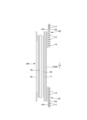
- FIG. 2 is a plan view showing the front surface of the pants-type disposable diaper in an unfolded state.
- FIG. 2 is a plan view showing the underside of the pants-type disposable diaper in an unfolded state.
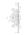
- This is a cross-sectional view of FIG. 1 along line 3-3.
- This is a cross-sectional view of FIG. 1 along line 4-4.
- This is a cross-sectional view of FIG. 1 along line 5-5.
- FIG. 2 is a plan view showing the surface of the inner body.
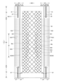
- FIG. 2 is a front perspective view of the pants-type disposable diaper, viewed diagonally from below.
- FIG. 4 is a cross-sectional view of a main part showing a mounted state.
- FIG. FIG. FIG. 11 is an enlarged plan view showing a main part of FIG. 10 .
- FIG. FIG. FIG. 13 is a plan view of the absorbent body in a deployed state showing examples of slits.
- each component member adjacent in the thickness direction is fixed or joined as necessary in the same manner as known diapers.
- the dotted pattern in the cross-sectional view indicates an adhesive such as a hot melt adhesive as the fixing or joining means.
- the hot melt adhesive can be applied by known methods such as slot application, continuous line or dotted line bead application, spiral, Z-shaped, wavy (regular or irregular) spray application, or pattern coating (transfer of hot melt adhesive using a letterpress method).
- the hot melt adhesive can be applied to the outer peripheral surface of the elastic member to fix the elastic member to the adjacent member.
- the hot melt adhesive for example, EVA-based, adhesive rubber-based (elastomer-based), polyolefin-based, polyester-polyamide-based, and other types are available, but there are no particular limitations on the types that can be used.
- material welding means such as heat sealing or ultrasonic sealing can be used. In a portion where liquid permeability in the thickness direction is required, adjacent components in the thickness direction are fixed or joined in an intermittent pattern.
- intermittent pattern application such as a spiral, Z-shape, or wave shape
- intermittent pattern application when applying to an area greater than the application width of one nozzle, intermittent pattern application such as a spiral, Z-shape, or wave shape can be performed with or without gaps in the width direction.
- material welding means such as heat sealing or ultrasonic sealing can be used.
- the constituent fibers of the nonwoven fabric can be selected without particular limitation, for example, synthetic fibers such as polyolefins such as polyethylene or polypropylene, polyesters, polyamides, etc. (including single-component fibers as well as composite fibers such as core-sheath fibers), regenerated fibers such as rayon or cupra, natural fibers such as cotton, etc., and these can also be used in combination.
- synthetic fibers such as polyolefins such as polyethylene or polypropylene, polyesters, polyamides, etc. (including single-component fibers as well as composite fibers such as core-sheath fibers), regenerated fibers such as rayon or cupra, natural fibers such as cotton, etc., and these can also be used in combination.
- the constituent fibers are crimped fibers.
- constituent fibers of the nonwoven fabric can be hydrophilic fibers (including fibers that have been made hydrophilic by a hydrophilizing agent), hydrophobic fibers, or water-repellent fibers (including fibers that have been made water-repellent by a water-repellent agent).
- nonwoven fabrics are generally classified into staple fiber nonwoven fabrics, long fiber nonwoven fabrics, spunbond nonwoven fabrics, meltblown nonwoven fabrics, spunlace nonwoven fabrics, thermal bond (air-through) nonwoven fabrics, needle punch nonwoven fabrics, point bond nonwoven fabrics, laminated nonwoven fabrics (including SMS nonwoven fabrics and SMMS nonwoven fabrics in which a meltblown layer is sandwiched between spunbond layers), etc., depending on the fiber length, sheet formation method, fiber bonding method, and laminated structure, but any of these nonwoven fabrics can be used.
- This pants-type disposable diaper 100 comprises a rectangular front outer body 12F constituting the front waist region FT, a rectangular rear outer body 12B constituting the rear waist region BT, and an inner body 200 joined to the middle of the outer bodies 12F, 12B in the width direction WD so as to extend from the front outer body 12F through the crotch region M to the rear outer body 12B.
- Both sides of the front outer body 12F and both sides of the rear outer body 12B are joined to form side seals 12A, whereby an opening formed by the front and rear edges of the outer bodies 12F, 12B becomes a waist opening WO through which the wearer's torso passes, and the portions on both sides of the inner body 200 in the width direction WD that are surrounded by the lower edges of the outer bodies 12F, 12B and the side edges of the inner body 200 respectively become leg openings LO through which the legs pass.
- the inner body 200 is a part that absorbs and retains excrement such as urine
- the outer bodies 12F and 12B are parts that support the inner body 200 against the wearer's body.
- the symbol Y indicates the total length of the diaper in the unfolded state (the length in the front-to-rear direction from the edge of the waist opening WO of the front body F to the edge of the waist opening WO of the back body B), and the symbol X indicates the total width of the diaper in the unfolded state.
- This pants-type disposable diaper 100 has a waist region T defined as the front-to-back range having the side seal 12A (the front-to-back range from the waist opening WO to the upper end of the leg opening LO), and an intermediate region L defined as the front-to-back range of the portion forming the leg opening LO (between the front-to-back region having the side seal 12A of the front body F and the front-to-back region having the side seal 12A of the rear body B).
- the portions of the front outer body 12F and the rear outer body 12B located in the waist region T i.e., the front waist region FT and the rear waist region BT, can be conceptually distinguished into a "waist portion” W which forms the edge of the waist opening, and a “lower waist portion” U which is the portion below this.
- the waist portion W is the portion closer to the waist opening WO than the boundary closest to the waist opening WO side, and when there is no such boundary, the portion extending further toward the waist opening WO side than the absorbent body 56 or the inner body 200 is the waist portion W.
- the length of these in the front-rear direction varies depending on the size of the product and can be determined appropriately, but as an example, the waist portion W can be 15 to 40 mm, and the lower waist portion U can be 65 to 120 mm.
- both side edges of the middle region L are narrowed in a U-shape or curved shape to fit around the wearer's legs, and this is the portion where the wearer's legs are inserted.
- the pants-type disposable diaper in the unfolded state has a generally hourglass shape.
- the inner body 200 can be fixed to the outer bodies 12F, 12B by a joining means such as heat sealing or ultrasonic sealing that uses material welding, or by a hot melt adhesive HM3.
- the back surface of the inner body 200 is fixed to the inner surface of the outer bodies 12F, 12B via the hot melt adhesive HM3.
- the fixing region 201 of the inner body 200 is provided in the region where the front waist portion FT and the rear waist portion BT overlap with the inner body 200. It is preferable that the fixing region of the inner body is provided over substantially the entire area except for the periphery of the region where the outer bodies 12F, 12B and the inner body 200 overlap.
- the exterior bodies 12F, 12B are composed of a rectangular front exterior body 12F that is a part that constitutes at least the front waistline FT (the waistline of the front body F) and a rectangular rear exterior body 12B that is a part that constitutes at least the rear waistline BT (the waistline of the rear body B).
- the front exterior body 12F and the rear exterior body 12B may not be continuous on the crotch side and may be separated in the front-to-back direction LD (two-piece exterior type), or may be continuous from the front body F through the crotch M to the rear body B (front and back integrated exterior type), although not shown.
- the separation distance 12d in the front-to-back direction in the two-piece exterior type can be, for example, about 40 to 60% of the total length Y.
- the lower edges of the front exterior body 12F and the rear exterior body 12B are linear along the width direction WD, but at least one of the lower edges of the front exterior body 12F and the rear exterior body 12B may be curved so as to follow the leg circumference.
- the interior body 200 is exposed between the front exterior body 12F and the rear exterior body 12B, so that the liquid-impermeable sheet 11 is not exposed on the rear surface of the interior body 200, it is preferable to provide a cover nonwoven fabric layer 13 on the rear surface of the interior body 200, which extends from between the front exterior body 12F and the interior body 200 to between the rear exterior body 12B and the interior body 200.
- the inner and outer surfaces of the cover nonwoven fabric layer 13 can be bonded to the opposing surfaces via a second hot melt adhesive HM2 and a third hot melt adhesive HM3, respectively.
- the nonwoven fabric used for the cover nonwoven fabric layer 13 can be appropriately selected from the same material as the exterior bodies 12F and 12B, for example.
- the front-to-rear dimension of the rear exterior body 12B is longer than that of the front exterior body 12F, the front exterior body 12F does not have a portion corresponding to the middle region L, and the rear exterior body 12B has a buttocks covering portion 14 that extends from the waist region T toward the middle region L, but the front exterior body 12F and the rear exterior body 12B have the same dimensions in the front-to-rear direction LD, and the front exterior body 12F and the rear exterior body 12B do not necessarily have a portion corresponding to the middle region L.
- the exterior bodies 12F, 12B are formed by bonding an outer sheet layer 12S and an inner sheet layer 12H adjacent to the outer and inner sides of the elastic members 15 to 17 described below, respectively, by a bonding means such as a hot melt adhesive or welding.
- the outer sheet layer 12S and the inner sheet layer 12H are formed by folding a single sheet material so that the crease is located on the waist opening side, but they can also be formed by bonding two sheets of material together, although this is not shown.
- the sheet material used for the outer sheet layer 12S and the inner sheet layer 12H is not particularly limited, but nonwoven fabric is preferable.
- the weight per sheet is preferably about 8 to 20 g/ m2 .
- the exterior bodies 12F, 12B have elastic members 15-17 attached between the outer sheet layer 12S and the inner sheet layer 12H at a predetermined stretch rate, forming a stretch region that stretches elastically in the width direction WD together with the elastic members 15-17.
- the stretch region can stretch between a natural length state in which it contracts together with the elastic members 15-17 and wrinkles or folds are formed, and an extended state in which it is extended in the width direction to a predetermined stretch rate together with the elastic members 15-17 and fully stretched without wrinkles.
- the elastic members 15-17 can be long and thin elastic members such as rubber thread (illustrated example), as well as known elastic members such as band-shaped, net-shaped, and film-shaped, without any particular restrictions.
- the elastic members 15-17 can be synthetic or natural rubber.
- the outer sheet layer 12S and the inner sheet layer 12H are bonded together, and the elongated elastic members 15-17 sandwiched between them can be fixed using at least one of various application methods of hot melt adhesives and material welding such as heat sealing and ultrasonic sealing. Since the flexibility is lost if the entire surface of the exterior bodies 12F, 12B is strongly fixed, it is preferable that the parts other than the adhesive parts of the elongated elastic members 15-17 are not bonded or are bonded weakly.
- hot melt adhesive is applied only to the outer peripheral surfaces of the elongated elastic members 15-17 using an application means such as a comb gun or a surwrap nozzle, and the elongated elastic members are sandwiched between the two sheet layers 12S, 12H, so that the elongated elastic members 15-17 are fixed to the two sheet layers 12S, 12H and fixed between the two sheet layers 12S, 12H only with the hot melt adhesive applied to the outer peripheral surfaces of the elongated elastic members 15-17.
- an application means such as a comb gun or a surwrap nozzle
- a plurality of waist elastic members 17 are attached between the outer sheet layer 12S and the inner sheet layer 12H in the waist portion W of the outer bodies 12F, 12B at intervals in the front-rear direction and in a state stretched in the width direction at a predetermined stretch rate, forming a continuous waist stretch region over the entire width direction WD.
- one or more members arranged in the region adjacent to the waist lower portion U may overlap the inner body 200, or may be provided on both sides of the width direction WD except for the width direction central portion overlapping the inner body 200.
- the waist elastic member 17 is preferably made of 2 to 15, and more preferably 4 to 10, rubber threads having a thickness of 300 to 940 dtex, and especially 470 to 780 dtex (in the case of synthetic rubber; in the case of natural rubber, a cross-sectional area of 0.05 to 1.5 mm2 , and especially 0.1 to 1.0 mm2 ) spaced at intervals of 2 to 12 mm, and especially 3 to 7 mm, and the resulting elongation rate in the width direction WD of the waist portion W is preferably 150 to 300%, and especially 200 to 280%. It is not necessary for the waist portion W to use elastic members of the same thickness or to have the same elongation rate in all of its front-to-rear direction LD, and for example the thickness or elongation rate may be different in some parts.
- a plurality of waist lower elastic members 15 made of elongated elastic members are attached at intervals in the front-rear direction and in a state stretched in the width direction at a predetermined stretch rate, forming waist lower stretchable regions on both sides in the width direction WD except for the width direction central portion overlapping with the inner body 200.
- the waist lower elastic members 15 are preferably about 5 to 30 pieces of rubber thread having a thickness of 300 to 940 dtex, particularly about 470 to 780 dtex (in the case of synthetic rubber; in the case of natural rubber, a cross-sectional area of 0.05 to 1.5 mm2 , particularly about 0.1 to 1.0 mm2 ) spaced at intervals of 1 to 15 mm, particularly 3 to 8 mm, and the resulting stretch rate in the width direction WD of the waist lower portion U is preferably about 200 to 350%, particularly about 240 to 300%. Furthermore, it is not necessary for the waist lower portion U to use elastic members of the same thickness or to have the same stretch rate all along the front-to-rear direction LD, and the thickness or stretch rate may be partially different.
- one or more buttocks cover elastic members 16 made of elongated elastic members are attached, spaced apart in the vertical direction and stretched along the width direction at a predetermined elongation rate, on both sides of the width direction WD except for the width direction central portion overlapping with the interior body 200, forming buttocks cover stretchable regions on both sides of the width direction WD except for the width direction central portion overlapping with the interior body 200.
- the buttocks-covering elastic member 16 is preferably made of 2 to 10 rubber threads having a thickness of 300 to 940 dtex, especially 470 to 780 dtex (in the case of synthetic rubber; in the case of natural rubber, a cross-sectional area of 0.05 to 1.5 mm2, especially 0.1 to 1.0 mm2 ) fixed at intervals of 5 to 40 mm, especially 5 to 20 mm, each with an elongation rate of 150 to 300%, especially 180 to 260%.
- the first region of the front waistband FT and rear waistband BT consisting of the portion overlapping the absorbent 56 and the portion between this and the side seal 12A, is an intermittent stretch band A1 having a non-stretch area 12X provided at least in the middle in the width direction WD of the portion overlapping the absorbent 56, and a stretch area provided between each of the non-stretch area 12X and the side seal 12A, and the second region located between this intermittent stretch band A1 and the waist opening WO is preferably a continuous stretch band A2 whose stretch area continues in the width direction WD from one side seal 12A to the other side seal 12A.
- the intermittent stretch band A1 in the illustrated example may extend beyond the range of the first region (beyond the absorbent 56) to the waist opening WO side as long as it includes the first region.
- the intermittent stretch band A1 only the first region in the rear waistband BT is the intermittent stretch band A1
- the area between the first region and the waist opening WO is the continuous stretch band A2
- the front waistband FT the area consisting of the part overlapping the fixed region 201 of the inner body 200 and the part between this and the side seal 12A (the area continuing to the waist opening WO side from the first region) is the intermittent stretch band A1, but this is not limited to this.
- the area consisting of the part overlapping the fixed region 201 of the inner body 200 and the part between this and the side seal 12A in both the front waistband FT and the rear waistband BT may be the intermittent stretch band A1, or only the first region may be the intermittent stretch band A1 in both the front waistband FT and the rear waistband BT.
- the intermittent stretch band A1 in the illustrated example is formed in a range in the front-to-back direction LD that includes only the lower waist stretch area with the lower waist elastic member 15, but the range may be expanded toward the waist opening WO to include a portion of the waist stretch area with the lower waist elastic member 17.
- the continuous stretch band A2 is formed only from a waist stretch area having a waist elastic member 17 in the front waist portion FT, and is formed from the entire waist stretch area having the waist elastic member 17 and a part of the lower waist stretch area including the lower waist elastic member 15 in the rear waist portion BT, but is not limited to this. Therefore, these may be reversed, and the continuous stretch bands A2 in both the front waist portion FT and the rear waist portion BT may be formed only from a waist stretch area having a waist elastic member 17, or may be formed from the entire waist stretch area having the waist elastic member 17 and a part of the lower waist stretch area having the lower waist elastic member 15.
- the absorbent body 56 will not shrink more than necessary in the width direction WD, and there will be no loss of fit, a poor appearance due to bulkiness, or loss of absorbency.
- Such intermittent stretch bands A1 include cases in which the elastic members 15, 16 are present only on both sides in the width direction WD, as well as cases in which the elastic members 15, 16 are present across the absorbent body 56 from one side to the other in the width direction WD, but the widthwise intermediate portion or all of the portion overlapping with the absorbent body 56 is a non-stretch region 12X where almost no contraction force acts (effectively equivalent to no elastic members 15, 16 being provided) due to the elastic members 15, 16 being cut into small pieces, etc., and both sides in the width direction WD are stretch regions (parts where contraction force acts).
- the non-stretchable region 12X is preferably located between both side edges of the inner body 200, and more preferably between both side edges of the absorbent body 56.
- the dimension of the width direction WD of the non-stretchable region 12X can be determined as appropriate, but is preferably 0.6 to 1.2 times the maximum width of the absorbent body 56, and more preferably 0.8 to 1.0 times.
- the dimension of the width direction WD of the non-stretchable region 12X is preferably 0.5 to 1.0 times the dimension of the width direction WD of the continuous stretchable band A2, and more preferably 0.6 to 0.8 times.
- the shape of the inner body 200 is arbitrary, but in the illustrated example, it is rectangular. As shown in Figures 3 to 5, the inner body 200 comprises a liquid-permeable top sheet 30 that faces the wearer's skin, a liquid-impermeable sheet 11, and an absorbent element 50 interposed therebetween.
- Reference numeral 60 denotes a side flap 60 having flat gathers.
- the top sheet 30 can be made of any liquid-permeable material, such as a perforated or non-perforated nonwoven fabric, a perforated plastic sheet, or the like, without any particular limitations. However, when the top sheet 30 also serves as a covering material for the liquid-impermeable sheet layer 64, as in the examples shown in Figures 3 and 4, the top sheet 30 is preferably made of a nonwoven fabric.
- the two sides of the top sheet 30 may be folded back at the side edges of the absorbent element 50 to the back side of the absorbent element 50, or may not be folded back and extend out to the side beyond the side edges of the absorbent element 50. If necessary, the overall width of the top sheet 30 may be made shorter than the overall width of the absorbent element 50, and both side edges of the top sheet 30 may be positioned above the absorbent element 50.
- an intermediate sheet (also called a "second sheet”) that has a faster liquid permeability than the top sheet 30 can be provided in order to quickly transfer liquid that has permeated the top sheet 30 to the absorbent body.
- This intermediate sheet is intended to quickly transfer liquid to the absorbent body, improve the absorption performance of the absorbent body, and prevent the "backflow” phenomenon of absorbed liquid from the absorbent body.
- the intermediate sheet can also be omitted.
- the material of the liquid-impermeable sheet 11 provided on the back side of the absorbent 56 is not particularly limited, but may be, for example, a plastic film made of a polyolefin resin such as polyethylene or polypropylene. In recent years, it is preferable to use a liquid-impermeable and moisture-permeable material that has been used with preference from the viewpoint of preventing stuffiness for the liquid-impermeable sheet 11.
- a microporous plastic film obtained by kneading an inorganic filler into a polyolefin resin such as polyethylene or polypropylene to form a sheet and then stretching the sheet in a uniaxial or biaxial direction is widely used.
- the liquid-impermeable sheet 11 can be extended into the side flaps to improve the waterproofing of the flat gathers, as in the example shown in Figures 3 and 4, or it can be made to a width that fits on the back side of the absorbent element 50 (not shown), or it can be folded back on the front side at the side edge of the absorbent element 50 and extend between the absorbent element 50 and the top sheet 30.
- the absorbent element 50 has an absorbent body 56 and a wrapping sheet 58 that wraps the entire absorbent body 56.
- the wrapping sheet 58 may be omitted.
- the absorbent body 56 is a mixture of pulp fibers and highly absorbent polymer particles.
- the basis weight of the pulp fibers can be, for example, about 80 to 450 g/ m2 , and more preferably about 80 to 200 g/ m2 .
- Superabsorbent polymer particles are mixed into the fiber aggregate.
- Superabsorbent polymer particles include not only “particles” but also "powder".
- the superabsorbent polymer particles can be the same as those used in this type of disposable diaper. For example, it is desirable that the percentage of particles remaining on a 500 ⁇ m standard sieve (JIS Z8801-1:2006) when sieved (shaking for 5 minutes) is 30% by weight or less, and it is also desirable that the percentage of particles remaining on a 180 ⁇ m standard sieve (JIS Z8801-1:2006) when sieved (shaking for 5 minutes) is 60% by weight or more.
- the material for the superabsorbent polymer particles is not particularly limited, but one with a water absorption capacity of 40 g/g or more (JIS K7223-1996 "Test method for water absorption capacity of superabsorbent resins") is preferable.
- the superabsorbent polymer particles include starch-based, cellulose-based and synthetic polymer-based ones, and examples of the superabsorbent polymer that can be used include starch-acrylic acid (salt) graft copolymers, saponified starch-acrylonitrile copolymers, crosslinked products of sodium carboxymethylcellulose and acrylic acid (salt) polymers.
- the shape of the superabsorbent polymer particles is preferably the commonly used powder-like one, but other shapes can also be used.
- the highly absorbent polymer particles preferably have a water absorption speed of 70 seconds or less, and particularly 40 seconds or less. If the water absorption speed is too slow, the liquid supplied to the absorbent body 56 tends to flow back out of the absorbent body 56, which is known as backflow.
- highly absorbent polymer particles with a gel strength of 1000 Pa or more are preferably used. This makes it possible to effectively suppress the sticky feeling after absorbing liquid, even when a bulky absorbent body 56 is used.
- the basis weight of the highly absorbent polymer particles can be appropriately determined according to the absorption amount required for the application of the absorbent body 56. Therefore, although it cannot be generally stated, it can be set to 50 to 350 g/ m2 . If the basis weight of the polymer is less than 50 g/ m2 , it becomes difficult to ensure the absorption amount. If it exceeds 350 g/ m2 , the effect becomes saturated.
- the ratio of fibers and superabsorbent polymer particles in the absorbent body 56 is not particularly limited, and for example, the weight ratio of pulp fibers:superabsorbent polymer particles can be 20:80 to 80:20, more preferably 40:60 to 60:40. In particular, when the weight ratio of pulp fibers:superabsorbent polymer particles is 40:60 to 60:40, a thinner absorbent body 56 can be obtained when compared for the same area and the same absorption amount.
- the thickness 56t of the absorbent body 56 is not particularly limited, but can be 1 to 20 mm, more preferably 2 to 5 mm.
- the absorbent body 56 is provided over a range in the front-to-rear direction LD, including the crotch area M.
- the absorbent body 56 preferably extends from the front waist area FT to the rear waist area BT.
- the portion of the absorbent body 56 located in the fixing area 201 of the inner body 200 is preferably fixed to the outer bodies 12F, 12B via a packaging sheet 58, a liquid-impermeable sheet 11, hot melt adhesive HM3, etc.
- the symbol 56X indicates the maximum width (total width) of the absorbent body 56.
- the absorbent body 56 has a generally rectangular shape as shown in the figure, since this makes it easier to ensure an adequate amount of absorption in the crotch area M, but it may have a constricted portion in the crotch area M (i.e., the absorbent body 56 has a minimum width portion located midway in the front-to-rear direction LD, and a widening portion that gradually widens from this minimum width portion to a maximum width portion forward of the crotch area M, and to a maximum width portion rearward of the crotch area M).
- the crotch area M refers to the area in the front-to-rear direction LD that has the slit described below, and the front and rear parts extend forward and rearward from this area, respectively.
- the absorbent body 56 has a pair of elongated slits 56L extending in the front-rear direction LD on one side and the other side of the crotch region M in the width direction WD.
- slits 56L By providing such slits 56L in the absorbent body 56, the crotch region M of the diaper can be deformed into a substantially U-shaped cross-sectional shape by encouraging the absorbent body 56 to bend along the slits 56L when worn, as shown in Fig. 8.
- a center region 56C defined between one slit 56L and the other slit 56L forms a bottom
- a pair of side regions 56S defined between the slits 56L on both sides in the width direction WD and the side edges 56e of the absorbent body 56 rise up to form side walls, so that the crotch region M of the diaper has a substantially U-shaped cross-sectional shape.
- the center region 56C and the pair of side regions 56S are shown by dot patterns in Fig. 14.
- the slit 56L may extend linearly along the front-rear direction LD as shown in FIG. 14(b), or may extend closer to the side edge of the absorbent body 56 as it moves from the middle of the slit 56L in the front-rear direction LD to the front and rear, respectively, as shown in FIG. 14(a) etc.
- at least one of the front and rear ends of the slit 56L may be separated from the side edge of the absorbent body 56 as shown in FIG. 14(a)(b), or one or both of the front and rear ends may reach the side edge of the absorbent body 56 as shown in FIG. 14(c)(d).
- the front and rear ends of the slit 56L may be of any suitable shape, for example, a straight line as shown in the example shown in FIG. 14(d), a curved bulge (semicircular arc, etc.) as shown in the example shown in FIG. 14(a) etc., or, although not shown, the corners of both ends may be rounded and the middle part may be straight.
- the width m1 of the slit 56L can be determined as appropriate, for example, to be 4 to 12 mm.
- the width m1 of the slit 56L may be constant in its length direction, or may vary.
- the dimensions and arrangement of the slit 56L in the front-to-rear direction LD can be determined as appropriate.
- the dimension m2 of the slit 56L in the front-to-rear direction LD (equal to the dimension of the crotch area M in the front-to-rear direction LD) can be 200 to 600% of the minimum spacing CW between the slits 56L, and more preferably 300 to 500%.
- the material may be a liquid-permeable material such as tissue paper, particularly crepe paper, nonwoven fabric, polylaminated nonwoven fabric, or a sheet with small holes.
- tissue paper particularly crepe paper, nonwoven fabric, polylaminated nonwoven fabric, or a sheet with small holes.
- the sheet is one from which the superabsorbent polymer particles do not escape.
- a nonwoven fabric instead of crepe paper, a hydrophilic nonwoven fabric having a dense layer is preferable.
- a nonwoven fabric As such a nonwoven fabric, a laminated nonwoven fabric (including SMS nonwoven fabric, SSMMS nonwoven fabric, etc.) in which one or more meltblown layers and one or more protective layers such as a non-spunbond layer that protects the meltblown layer are laminated is particularly preferable, and the material may be polypropylene, a polyethylene/polypropylene composite material, or the like.
- the basis weight of the packaging sheet 58 may be, for example, 5 to 40 g/m 2 , preferably 8 to 20 g/m 2 .
- the packaging structure of the packaging sheet 58 can be determined as appropriate, but from the standpoint of ease of manufacture and prevention of leakage of superabsorbent polymer particles from the front and rear edges, it is preferable for the packaging sheet 58 to be wrapped around the front, back and both sides of the absorbent body 56 in a cylindrical shape.
- the packaging sheet 58 may extend beyond the front and rear edges of the absorbent body, or as shown in the illustrated example, the front and rear edges of the packaging sheet 58 may be approximately aligned with the front and rear edges of the absorbent body.
- the inner body 200 preferably has side flaps 60.
- the side flaps 60 are a pair of portions extending from the side edges of the absorbent body 56 on both sides in the width direction WD, and each extends in the front-rear direction LD from an area overlapping with the waist circumference stretchable area of the front body F (in the illustrated example, an area having the waist lower elastic member 15) to an area overlapping with the waist circumference stretchable area of the back body B (in the illustrated example, an area having the waist lower elastic member 15).
- the side flaps 60 also have side nonwoven fabric 66 extending from the front surface of the side flap 60 through the side edges of the side flap 60 to the back surface of the side flap 60, and elongated gather elastic members 631 to 633 provided between the front surface portion 61 and the back surface portion 62 along the front-rear direction LD.
- the front surface portion 61 and the back surface portion 62 extend over the entire front-rear direction LD of the side flap 60.
- the surface portion 61 is formed by the folded-back portion 66r of the side nonwoven fabric 66, but is not limited thereto.
- the front end and rear end of the side flap 60 are not contracted in the front-rear direction LD together with the gathered elastic members 631-633, and form a side non-stretchable region 70 having a fixed portion 67 where the surface portion 61 is fixed to the back portion 62.
- the portion between the front and rear side non-stretchable regions 70 of the side flap 60 is a flat gathered region 80 to which the gathered elastic members 631-633 are fixed, contracted in the front-rear direction LD together with the gathered elastic members 631-633, and stretchable in the front-rear direction LD together with the gathered elastic members 631-633.
- This pants-type disposable diaper does not have three-dimensional gathers that rise up on the front side, and has only flat gathers of the side flap 60.
- the front surface portion 61 is indirectly fixed to the back surface portion 62 via the liquid-impermeable sheet layer 64, but if no other components such as the liquid-impermeable sheet layer 64 are interposed, the front surface portion 61 will be directly fixed.
- the dimension of the side non-stretchable region 70 in the front-to-rear direction LD may be different at the front end and rear end of the side flap 60 as shown in the example, or may be the same.
- the reference symbol 60w in the figure indicates the dimension of the side flap 60 in the width direction WD.
- the reference symbol w1 indicates the distance in the width direction WD between the fixing part 67 and the side edge of the side non-stretchable region 70 (first distance)
- the reference symbol w2 indicates the dimension in the width direction WD of the part of the both sides (side flaps) of the inner body that is not fixed to the outer body 12 (second distance)
- the reference symbol w3 indicates the dimension in the width direction WD of the fixing part 67
- the reference symbol w4 indicates the distance in the width direction WD between the fixing part 67 and the side edge of the absorbent body 56 (third distance)
- the reference symbol w5 indicates the distance in the width direction WD between the fixing part 67 and the edge of the center side of the width direction WD of the surface part 61 (fourth distance).
- the gathered elastic members 631-633 may be elongated elastic members such as rubber threads or rubber strips. When rubber threads are used, the thickness of the gathered elastic members 631-633 is preferably 400-950 dtex, and more preferably 470-780 dtex. The elongation of the gathered elastic members 631-633 is preferably 200-320%, and more preferably 240-320%.
- reference numeral 631 indicates a first gathered elastic member located first counting from the absorbent body 56 side
- reference numeral 632 indicates a second gathered elastic member located second
- reference numeral 633 indicates a third gathered elastic member located third or later.
- the symbol d1 indicates the distance in the width direction WD (first distance) between the side edge of the widest part of the absorbent body 56 and the first gather elastic member 631
- the symbol d2 indicates the distance in the width direction WD between the first gather elastic member 631 and the second gather elastic member 632 (second distance)
- the symbol d3 indicates the distance in the width direction WD between the second gather elastic member 632 and the third gather elastic member 633 and the distance in the width direction WD between adjacent third gather elastic members 633 (third distance).
- At least one of hot melt adhesives applied by various application methods and material welding fixing means such as heat sealing and ultrasonic sealing can be used to bond adjacent layers in the thickness direction and to fix the gathered elastic members 631-633 sandwiched between them. Since bonding the entire surfaces of adjacent layers on the front and back sides of the gathered elastic members 631-633 impairs flexibility, it is preferable that the parts other than the adhesive parts of the gathered elastic members 631-633 are not bonded or are weakly bonded.
- hot melt adhesive is applied only to the outer peripheral surfaces of the gathered elastic members 631-633 by an application means such as a comb gun or a surwrap nozzle, and the gathered elastic members 631-633 are sandwiched between adjacent layers on the front and back sides, so that the hot melt adhesive applied only to the outer peripheral surfaces of the gathered elastic members 631-633 fixes the gathered elastic members 631-633 to the layers adjacent to them on the front and back sides, and fixes the layers adjacent to the front and back sides of the gathered elastic members 631-633 to each other.
- an application means such as a comb gun or a surwrap nozzle
- first hot melt adhesive HM1 in the illustrated example can be applied to secure it.
- a nonwoven fabric that is soft and has excellent uniformity and hiding properties such as a spunbond nonwoven fabric (SS, SSS, etc.), an SMS nonwoven fabric (SMS, SSMMS, etc.), or a meltblown nonwoven fabric, which has been subjected to a water repellent treatment with silicone or the like as necessary, can be suitably used, and the fiber basis weight is preferably about 10 to 30 g/m 2.
- the absorbent body 56 is preferably provided with grooves 53 having bottoms 51 that are recessed from the surface of the absorbent body 56 into the absorbent body 56 and compressed in the thickness direction.
- the bottoms 51 of the grooves 53 are high-density parts that are compressed by pressing (direct pressure) and have a substantially uniform thickness.
- the parts other than the bottoms 51 are referred to as non-compressed parts 52.
- the non-compressed parts 52 are parts that are thicker and have a lower density than the bottoms 51, but even in the non-compressed parts 52, the absorbent body 56 is deformed as if pulled by the compression of the bottoms 51 near the periphery of the bottoms 51, so that the density increases as it approaches the bottoms 51. As long as the non-compressed parts 52 are thicker and have a lower density than the bottoms 51, the entire non-compressed parts 52 may be compressed in the thickness direction simultaneously with, before, or after the compression process that forms the bottoms 51.
- the shape and arrangement of the non-compressed parts 52 are determined according to the shape and arrangement of the bottoms 51.
- the grooves 53 in the absorbent body 56 may be formed by subjecting only the absorbent body 56 to embossing with or without heating, but they may also be formed by embossing the absorbent body 56 and other laminated members, such as the absorbent element 50 (i.e., together with the packaging sheet 58) and the inner body 200, in a laminated state.
- the compressed bottom 51 has a high density and high rigidity, so that the shape retention of the center region 56C and the side region 56S is improved.
- the compressed bottom 51 since providing a compressed bottom 51 leads to an improvement in rigidity, if the compressed bottom 51 is provided in a uniform dense pattern over the center region 56C and the side region 56S in consideration of the shape retention after absorbing urine, the part located at the bottom (center region 56C) becomes difficult to bend and difficult to deform following the crotch width when the crotch region M is deformed into a substantially U-shaped cross-sectional shape (decreased following deformation). Therefore, it is preferable that the thickness of the bottom 51 of the groove 53 is constant and the area ratio of the bottom 51 of the groove 53 is low in the center region 56C compared to the side region 56S.
- the center region 56C may have a constant area ratio of the bottoms 51 of the grooves 53 and a thicker bottom 51 of the grooves 53 than the side regions 56S, or the area ratio of the bottoms 51 of the grooves 53 may be lower and the thickness of the bottoms 51 of the grooves 53 may be thicker.
- the absorbent 56 is easily bent at the slits 56L, with the center region 56C forming the bottom and each side region 56S rising up to form a side wall, which not only makes it easier for the crotch region M of the diaper to have an approximately U-shaped cross-section, but also increases the rigidity of the side walls (i.e., the urine receiving space SP is less likely to collapse), and provides an absorption function.
- Both the center region 56C and the side region 56S have grooves 53 in a predetermined pattern that extend from at least one of the front and back surfaces of the absorbent element 50 into the absorbent body 56 and have bottoms 51 compressed in the thickness direction.
- the absorbent body 56 is more likely to maintain its shape even after absorbing urine.
- the center region 56C is relatively flexible and the side regions 56S are relatively shape-retaining, so that when the crotch portion M of the diaper is worn in a U-shaped cross-section, the side walls become more rigid and the urine receiving space SP becomes less likely to collapse, while the bottom portion becomes more easily bent and easily deformed to conform to the crotch width.
- the grooves 53 are provided in a pattern that is continuous in the width direction WD over a range of 60% or more of the front-rear direction LD of the center region 56C and the side regions 56S, they may be formed over a range of 80% or more of the front-rear direction LD, or may be formed over the entire front-rear direction LD as in the illustrated example, or may be formed only in a range of 60% or more but less than 100% of the front-rear direction LD from the front end or rear end of the center region 56C and the side regions 56S, or may be formed only in the intermediate portion between the front end and rear end of the center region 56C and the side regions 56S.
- the pattern of the grooves 53 is uniformly continuous over the entire range of the front-rear direction LD from the front side of the front end of the center region 56C and the side regions 56S to the rear side of the rear end of the center region 56C and the side regions 56S (the entire front-rear direction LD of the absorbent body 56 in the illustrated example), since it is unnecessary to position the grooves 53 in the front-rear direction LD, and manufacturing is easy.
- the area including 60% or more of the center region 56C and side region 56S in the front-to-rear direction LD and the other areas may have different patterns of grooves 53.
- the dimensions and number of the bottoms 51 of the grooves 53 can be determined as appropriate, but it is preferable that the depth 51h of the bottoms 51 (thickness 56t of the absorbent 56 - thickness 51t of the groove bottoms) is 0.5 to 5 mm, and the area ratio of the bottoms 51 of the grooves 53 (the ratio of the area of the bottoms 51 to the surface of the absorbent element 50) is 20 to 40%.
- the grooves 53 having the bottom 51 may be arranged in a continuous grid pattern as shown in Figs. 10 and 11, or, although not shown, multiple grooves 53 along the width direction WD may be arranged at intervals in the front-rear direction LD (horizontal stripe pattern), multiple grooves 53 along the diagonal direction may be arranged at intervals in a direction perpendicular to the continuous direction of the grooves 53 (diagonal stripe pattern), multiple grooves 53 extending in a wavy line may be arranged at intervals in the front-rear direction LD, or other geometric patterns may be arranged, or continuous patterns may be arranged with motifs of letters, animals, plants, etc.
- the non-compressed portions 52 are intermittently arranged at least in the front-rear direction LD.
- the pulp fibers and superabsorbent polymer particles constituting the absorbent 56 are constrained within the unit frame 54 (minimum frame) consisting of the bottom 51 compressed in the thickness direction, which contributes to reducing twisting and cracking of the absorbent 56.
- the width 51w of the bottom 51 of the groove 53 can be determined as appropriate, but in general, it is preferable for it to be approximately 1 to 3 mm.
- the thickness 51t of the bottom 51 of the groove 53 can be determined as appropriate, but in general, it is preferably 5 to 40%, and more preferably 5 to 30%, of the maximum thickness 50t of the absorbent element 50.
- the shape of the unit frames 54 is not particularly limited, and may be an approximately square shape as in the illustrated example, an approximately rhombus (excluding a square), or another polygonal shape such as an approximately rectangular shape, an approximately square shape, an approximately triangular shape, etc. Furthermore, as long as the bottoms 51 of the grooves are arranged in a lattice pattern, the unit frames 54 may have different shapes.
- One preferred grid pattern for the grooves 53 is a diagonal grid pattern, as shown in the example in Figures 10 and 11, consisting of first portions 51a extending in a direction inclined by 40 to 60 degrees (more preferably 45 to 50 degrees) clockwise in plan view with respect to the front-to-rear direction LD, and second portions 51b extending in a direction inclined by 40 to 60 degrees (more preferably 45 to 50 degrees) counterclockwise in plan view with respect to the front-to-rear direction LD.
- the shape of the unit frame 54 is approximately rhombus. It is particularly preferred that the angle of the first portions 51a and second portions 51b with respect to the front-to-rear direction LD is 45 degrees.
- the dimensions of the unit frame 54 can be set as appropriate, but if they are too large, the effect of improving rigidity will be poor, and if they are too small, they will be too hard. Therefore, in normal cases, it is preferable that the dimension 54x of the width direction WD of the unit frame 54 be approximately 15 to 20 mm. Also, it is preferable that the dimension 54y of the front-rear direction LD of the unit frame 54 be approximately 15 to 20 mm.
- the width of the bottom 51 of the groove 53 can be changed while keeping the pattern of the groove 53 approximately constant, or the pattern of the groove 53 can be changed while keeping the width 51w of the bottom 51 of the groove 53 approximately constant, or both the pattern of the groove 53 and the width 51w of the bottom 51 of the groove 53 can be changed.
- the width 51w of the bottom 51 of the groove 53 is increased to increase the area ratio of the bottom 51 of the groove 53, the feeling of the hard bottom 51 of the groove 53 is easily transmitted to the skin. Therefore, as shown in the illustrated example, it is preferable to change the pattern of the groove 53 (specifically, the number of grooves 53 per unit area) while keeping the width 51w of the bottom 51 of the groove 53 approximately constant.
- the change in the shape retention of the absorbent 56 is not large, and the effect on the absorption performance such as liquid diffusion is large, and the ease of manufacture is also reduced. Therefore, although it is possible to change the thickness of the bottom 51 of the groove 53 while keeping the area ratio of the bottom 51 of the groove 53 approximately constant, it is more preferable to change the area ratio of the bottom 51 of the groove 53 while keeping the thickness of the bottom 51 of the groove 53 approximately constant.
- FIGS. 10 to 13 show some preferred examples of groove patterns.
- the width 51w and thickness of the bottom 51 of the groove 53 are approximately constant, while the pattern of the groove 53 changes in the width direction WD so that the area ratio of the bottom 51 of the groove 53 is larger in the side region 56S than in the center region 56C.
- the groove 53 has a lattice pattern, as shown in Figures 10, 11, and 12, by combining a plurality of unit frame 54 shapes to form a pattern in which the area of the unit frame 54 gradually decreases from the center in the width direction WD toward both side edges, the area ratio of the bottom 51 of the groove 53 in the side region 56S can be made higher than that in the center region 56C. Also, as shown in Figure 13, by combining unit frames 54 of the same shape (diamond (square) in the illustrated example) but different sizes to form a pattern in which the area of the unit frame 54 gradually decreases from the center in the width direction WD toward both side edges, the area ratio of the bottom 51 of the groove 53 in the side region 56S can be made higher than that in the center region 56C.
- the size of the area of each unit frame 54 can be determined as appropriate, but of a pair of unit frames 54 adjacent in the width direction WD so as to have a common side, it is preferable that the area of the larger unit frame 54 is 1.1 to 2.5 times the area of the smaller unit frame 54. It is also preferable that the maximum area of the unit frame 54 made up of grooves 53 in the center region 56C is 1.5 to 4 times the maximum area of the unit frame 54 made up of grooves 53 in the side region 56S. In this case, it is preferable that the area of the unit frame 54 made up of grooves 53 in the center region 56C is 150 to 500 mm2 .
- the pattern of grooves 53 in the example shown in Figures 10 and 11 is a diagonal grid.
- a diamond-shaped first unit frame 54a having the largest area is lined up without any gaps in the center of the width direction WD to form a group continuing in the front-to-back direction LD, and along the side edges of the group of first unit frames 54a, a rectangular second unit frame 54b having one side in common with the first unit frame 54a and a short side that intersects with the common side having a length that is 2/3 of the length of the common side, and an L-shaped third unit frame 54c having two sides in common with the first unit frame 54a and a short side that intersects with the common side having a length that is 2/3 of the length of the common side are lined up without any gaps to form a group continuing in the front-to-back direction LD, and along the side edges of the group of the second and third unit frames 54b and 54c, a diamond-shaped fourth unit frame 54d having a side length that is 2/3 of the length of
- the pattern of the grooves 53 in the example shown in Fig. 12 is also a diagonal lattice pattern.
- the diamond-shaped first unit frames 54e having the largest area are lined up without gaps in the center of the width direction WD to form a group continuing in the front-to-rear direction LD, and along the side edges of the group of first unit frames 54e, diamond-shaped second unit frames 54f each having a side length 1/2 that of the first unit frame 54e and L-shaped third unit frames 54g each having two long sides the same as that of the first unit frame 54e and four short sides each having a side length 1/2 that of the first unit frame 54e are lined up without gaps in the group continuing in the front-to-rear direction LD, and along the side edges of the group of third unit frames 54g, diamond-shaped second unit frames 54f each having a side length 1/2 that of the first unit frame 54e are lined up without gaps in the group continuing in the front-to-rear direction LD.
- the maximum area of unit frames 54e-g is 1, and
- the pattern of the grooves 53 in the example shown in FIG. 13 is also a diagonal lattice pattern.
- the diamond-shaped first unit frames 54h having the largest area are lined up without gaps in the center of the width direction WD and form a group continuing in the front-to-back direction LD, and along the side edges of the group of first unit frames 54h, diamond-shaped second unit frames 54i whose side length is 1/2 that of the first unit frames 54h are lined up without gaps and form a group continuing in the front-to-back direction LD, and along the side edges of the group of second unit frames 54i, diamond-shaped third unit frames 54j whose side length is 1/3 that of the first unit frames 54h are lined up without gaps and form a group continuing in the front-to-back direction LD.
- the area of the unit frames 54h-j is 1/9 at maximum.
- the groove 53 has a lattice pattern, as in the example shown in Figure 10, if the dimension in the width direction WD of the unit frame 54 in the side region 56S is 0.5 times or less, preferably 0.3 to 0.5 times, the minimum dimension in the width direction WD of the side region 56S, there will be at least one unit frame 54 in the side region 56S, which is particularly preferable in terms of both improved rigidity and improved diffusion, even if the position of the lattice pattern is slightly shifted due to manufacturing errors.
- the pattern of the grooves 53 in both side regions 56S consists only of a slit adjacent frame 54m consisting of the side edge of the slit 56L and the groove 53, a side edge adjacent frame 54n consisting of the side edge 56e of the absorbent body 56 and the groove 53, and a complete (without missing parts) unit frame 54 having the same dimensions and shape, and it is preferable that the area of each slit adjacent frame 54m and the area of each side edge adjacent frame 54n are smaller than the area of the unit frame 54, because when the diaper has a substantially U-shaped cross section, the rigidity of the side walls is particularly high, making the urine receiving space SP less likely to collapse.
- the area of some or all of the slit adjacent frames 54m may be larger than the area of the unit frame 54, as in the examples shown in Figures 12 and 13.
- the pattern of the grooves 53 in the center region 56C has a complete (without missing parts) unit frame 54 having the same dimensions and shape, as in the illustrated example.
- it may have a slit adjacent frame 54m consisting of the side edge of the slit 56L and the groove 53.
- the pattern of the groove 53 in at least one of the side region 56S and the center region 56C can be a pattern consisting of only complete (no missing) unit frames 54.
- the shape of the absorbent 56 and the shape of the slits 56L are as described above, but as shown in FIG. 14(a), if both side edges of the absorbent 56 extend linearly in the front-to-rear direction LD, and the pair of slits 56L extend from the middle in the front-to-rear direction LD toward the front and rear, respectively, so as to approach the side edges 56e of the absorbent 56, not only will the side walls fit easily around the inside of the thighs when the crotch portion M of the diaper has a roughly U-shaped cross section, but the side walls will also become lower in height toward the front and rear, making them less likely to fold, and therefore the urine receiving space SP will be particularly less likely to collapse in the vicinity of these areas.
- Front-to-rear direction refers to the direction indicated by the symbol LD in the drawing (longitudinal direction), and "width direction” refers to the direction indicated by the symbol WD in the drawing (left-to-right direction), with the front-to-rear direction and width direction being perpendicular to each other.
- Front side means the side closest to the wearer's skin when worn
- back side means the side furthest from the wearer's skin when worn
- Elongation rate refers to the value when the natural length is 100%. For example, an elongation rate of 200% is synonymous with an elongation ratio of 2 times.
- Gel strength is measured as follows. 1.0 g of superabsorbent polymer is added to 49.0 g of artificial urine (a mixture of urea: 2 wt%, sodium chloride: 0.8 wt%, calcium chloride dihydrate: 0.03 wt%, magnesium sulfate heptahydrate: 0.08 wt%, and ion-exchanged water: 97.09 wt%) and stirred with a stirrer. The resulting gel is left in a thermo-hygrostat at 40°C x 60% RH for 3 hours, then returned to room temperature and the gel strength is measured with a curd meter (I.techno Engineering: Curdmeter-MAX ME-500).
- ⁇ "Balance weight is measured as follows. After pre-drying the sample or test piece, leave it in a test room or device under standard conditions (test location: temperature 23 ⁇ 1°C, relative humidity 50 ⁇ 2%) until it reaches a constant weight. Pre-drying refers to bringing the sample or test piece to a constant weight in an environment at a temperature of 100°C. Note that pre-drying is not necessary for fibers with an official moisture regain of 0.0%. Using a sample collection template (100mm x 100mm), cut out a sample measuring 100mm x 100mm from the test piece that has reached a constant weight. Measure the weight of the sample and multiply it by 100 to calculate the weight per square meter, which is the basis weight.
- the "thickness" of thick components such as the absorber 56, the absorbent element 50, and the bottom 51 of the groove is measured using a thickness gauge from Ozaki Manufacturing Co., Ltd. (Peacock, dial thickness gauge, model H (measurement range 0-10 mm, measurement area circular terminal with diameter 10 mm, measurement force approximately 1.7 N, pressure approximately 21.7 KPa)) with the sample and thickness gauge held horizontally.
- the "thickness" of a thin sheet such as a nonwoven fabric is automatically measured using an automatic thickness measuring device (KES-G5 handy compression measurement program) under the conditions of a load of 0.098 N/cm 2 and a pressurized area of 2 cm 2 .
- KS-G5 handy compression measurement program automatic thickness measuring device
- the water absorption rate is the "time to the end point" when JIS K7224-1996 "Water absorption rate test method for superabsorbent polymers" is performed using 2 g of superabsorbent polymer and 50 g of physiological saline.
- “Expanded state” means a flat, unfolded state without contraction (including any contraction, such as contraction due to elastic members) or sagging.
- Maximum stretch means the maximum stretch in the stretch direction in the stretch region (i.e. the stretch at the elastic limit, which is equal to the stretch in the unfolded state), and is expressed as a percentage of the unfolded length, with the natural length being 100%.
- the dimensions of each part refer to the dimensions in the unfolded state, not the natural length.
- test or measurement shall be performed in a test room or device under standard conditions (the test location shall be a temperature of 23 ⁇ 1°C and a relative humidity of 50 ⁇ 2%).
- the present invention can be used with all disposable diapers, including tape-type disposable diapers and pad-type disposable diapers.
Landscapes
- Health & Medical Sciences (AREA)
- Epidemiology (AREA)
- Engineering & Computer Science (AREA)
- Biomedical Technology (AREA)
- Heart & Thoracic Surgery (AREA)
- Vascular Medicine (AREA)
- Life Sciences & Earth Sciences (AREA)
- Animal Behavior & Ethology (AREA)
- General Health & Medical Sciences (AREA)
- Public Health (AREA)
- Veterinary Medicine (AREA)
- Absorbent Articles And Supports Therefor (AREA)
Priority Applications (2)
| Application Number | Priority Date | Filing Date | Title |
|---|---|---|---|
| EP24823063.3A EP4710905A1 (en) | 2023-06-16 | 2024-04-02 | Disposable diaper |
| CN202480018796.5A CN120813321A (zh) | 2023-06-16 | 2024-04-02 | 一次性纸尿裤 |
Applications Claiming Priority (2)
| Application Number | Priority Date | Filing Date | Title |
|---|---|---|---|
| JP2023-099311 | 2023-06-16 | ||
| JP2023099311A JP2024179960A (ja) | 2023-06-16 | 2023-06-16 | 使い捨ておむつ |
Publications (1)
| Publication Number | Publication Date |
|---|---|
| WO2024257440A1 true WO2024257440A1 (ja) | 2024-12-19 |
Family
ID=93851866
Family Applications (1)
| Application Number | Title | Priority Date | Filing Date |
|---|---|---|---|
| PCT/JP2024/013548 Ceased WO2024257440A1 (ja) | 2023-06-16 | 2024-04-02 | 使い捨ておむつ |
Country Status (4)
| Country | Link |
|---|---|
| EP (1) | EP4710905A1 (https=) |
| JP (1) | JP2024179960A (https=) |
| CN (1) | CN120813321A (https=) |
| WO (1) | WO2024257440A1 (https=) |
Citations (8)
| Publication number | Priority date | Publication date | Assignee | Title |
|---|---|---|---|---|
| JP2003033397A (ja) * | 2001-07-25 | 2003-02-04 | Daio Paper Corp | 吸収性物品 |
| JP2004016648A (ja) * | 2002-06-19 | 2004-01-22 | Crecia Corp | 吸収コアを備えた使い捨ておむつ |
| JP2017047147A (ja) * | 2015-09-10 | 2017-03-09 | ユニ・チャーム株式会社 | 吸収パッド |
| JP2017136273A (ja) * | 2016-02-04 | 2017-08-10 | 王子ホールディングス株式会社 | 吸収性物品 |
| JP2020000591A (ja) * | 2018-06-29 | 2020-01-09 | 花王株式会社 | 吸収性物品 |
| JP2021000236A (ja) | 2019-06-20 | 2021-01-07 | ユニ・チャーム株式会社 | 吸収性物品、吸収体の製造方法、及び吸収体の製造装置 |
| JP2023068194A (ja) * | 2021-04-20 | 2023-05-16 | ユニ・チャーム株式会社 | 吸収性物品 |
| JP2023089757A (ja) * | 2021-12-16 | 2023-06-28 | ユニ・チャーム株式会社 | 吸収性物品 |
-
2023
- 2023-06-16 JP JP2023099311A patent/JP2024179960A/ja active Pending
-
2024
- 2024-04-02 WO PCT/JP2024/013548 patent/WO2024257440A1/ja not_active Ceased
- 2024-04-02 EP EP24823063.3A patent/EP4710905A1/en active Pending
- 2024-04-02 CN CN202480018796.5A patent/CN120813321A/zh active Pending
Patent Citations (8)
| Publication number | Priority date | Publication date | Assignee | Title |
|---|---|---|---|---|
| JP2003033397A (ja) * | 2001-07-25 | 2003-02-04 | Daio Paper Corp | 吸収性物品 |
| JP2004016648A (ja) * | 2002-06-19 | 2004-01-22 | Crecia Corp | 吸収コアを備えた使い捨ておむつ |
| JP2017047147A (ja) * | 2015-09-10 | 2017-03-09 | ユニ・チャーム株式会社 | 吸収パッド |
| JP2017136273A (ja) * | 2016-02-04 | 2017-08-10 | 王子ホールディングス株式会社 | 吸収性物品 |
| JP2020000591A (ja) * | 2018-06-29 | 2020-01-09 | 花王株式会社 | 吸収性物品 |
| JP2021000236A (ja) | 2019-06-20 | 2021-01-07 | ユニ・チャーム株式会社 | 吸収性物品、吸収体の製造方法、及び吸収体の製造装置 |
| JP2023068194A (ja) * | 2021-04-20 | 2023-05-16 | ユニ・チャーム株式会社 | 吸収性物品 |
| JP2023089757A (ja) * | 2021-12-16 | 2023-06-28 | ユニ・チャーム株式会社 | 吸収性物品 |
Also Published As
| Publication number | Publication date |
|---|---|
| CN120813321A (zh) | 2025-10-17 |
| EP4710905A1 (en) | 2026-03-18 |
| JP2024179960A (ja) | 2024-12-26 |
Similar Documents
| Publication | Publication Date | Title |
|---|---|---|
| JP5964389B2 (ja) | パンツタイプ使い捨ておむつ | |
| CN113518604B (zh) | 短裤型一次性穿着物品 | |
| JP2020156929A5 (https=) | ||
| JP7476139B2 (ja) | 使い捨ておむつ | |
| CN110691575B (zh) | 短裤型一次性尿布 | |
| JP7456731B2 (ja) | 使い捨て着用物品 | |
| JP2020168221A (ja) | パンツタイプ使い捨て着用物品 | |
| JP2020168221A5 (https=) | ||
| WO2024257440A1 (ja) | 使い捨ておむつ | |
| JP6986403B2 (ja) | パンツタイプ使い捨ておむつ及びその製造方法 | |
| JP7750789B2 (ja) | パンツタイプ使い捨て着用物品 | |
| JP6084327B2 (ja) | パンツタイプ使い捨ておむつ | |
| JP7767222B2 (ja) | パンツタイプ使い捨て着用物品 | |
| WO2024195196A1 (ja) | パンツタイプ使い捨て着用物品 | |
| JP7424811B2 (ja) | 使い捨て着用物品 | |
| JP7538674B2 (ja) | パンツタイプ使い捨て着用物品 | |
| JP2023162995A5 (https=) | ||
| JP2024179960A5 (https=) | ||
| JP2020195420A (ja) | パンツタイプ使い捨て着用物品 | |
| JP2020195420A5 (https=) | ||
| WO2025075077A1 (ja) | 使い捨て着用物品 | |
| JP2023162994A5 (https=) | ||
| JP2019170555A (ja) | 使い捨て着用物品の伸縮構造、及びこの伸縮構造を有するパンツタイプ使い捨て着用物品 | |
| JP2024074409A (ja) | パンツタイプ使い捨ておむつ | |
| JP2025031005A (ja) | パンツタイプ吸収性物品 |
Legal Events
| Date | Code | Title | Description |
|---|---|---|---|
| 121 | Ep: the epo has been informed by wipo that ep was designated in this application |
Ref document number: 24823063 Country of ref document: EP Kind code of ref document: A1 |
|
| WWE | Wipo information: entry into national phase |
Ref document number: 202480018796.5 Country of ref document: CN |
|
| REG | Reference to national code |
Ref country code: BR Ref legal event code: B01A Ref document number: 112025020310 Country of ref document: BR |
|
| WWE | Wipo information: entry into national phase |
Ref document number: 2501006860 Country of ref document: TH |
|
| WWP | Wipo information: published in national office |
Ref document number: 202480018796.5 Country of ref document: CN |
|
| WWE | Wipo information: entry into national phase |
Ref document number: 2024823063 Country of ref document: EP |
|
| ENP | Entry into the national phase |
Ref document number: 2024823063 Country of ref document: EP Effective date: 20251209 |
|
| ENP | Entry into the national phase |
Ref document number: 2024823063 Country of ref document: EP Effective date: 20251209 |
|
| ENP | Entry into the national phase |
Ref document number: 2024823063 Country of ref document: EP Effective date: 20251209 |
|
| ENP | Entry into the national phase |
Ref document number: 2024823063 Country of ref document: EP Effective date: 20251209 |
|
| NENP | Non-entry into the national phase |
Ref country code: DE |
|
| ENP | Entry into the national phase |
Ref document number: 2024823063 Country of ref document: EP Effective date: 20251209 |
|
| ENP | Entry into the national phase |
Ref document number: 2024823063 Country of ref document: EP Effective date: 20251209 |
|
| ENP | Entry into the national phase |
Ref document number: 2024823063 Country of ref document: EP Effective date: 20251209 |
|
| ENP | Entry into the national phase |
Ref document number: 2024823063 Country of ref document: EP Effective date: 20251209 |
|
| WWP | Wipo information: published in national office |
Ref document number: 2024823063 Country of ref document: EP |