WO2024257437A1 - 車両空調システム - Google Patents
車両空調システム Download PDFInfo
- Publication number
- WO2024257437A1 WO2024257437A1 PCT/JP2024/012730 JP2024012730W WO2024257437A1 WO 2024257437 A1 WO2024257437 A1 WO 2024257437A1 JP 2024012730 W JP2024012730 W JP 2024012730W WO 2024257437 A1 WO2024257437 A1 WO 2024257437A1
- Authority
- WO
- WIPO (PCT)
- Prior art keywords
- air conditioning
- coolant
- vehicle
- refrigerant
- module
- Prior art date
- Legal status (The legal status is an assumption and is not a legal conclusion. Google has not performed a legal analysis and makes no representation as to the accuracy of the status listed.)
- Ceased
Links
Images


Classifications
-
- B—PERFORMING OPERATIONS; TRANSPORTING
- B60—VEHICLES IN GENERAL
- B60H—ARRANGEMENTS OF HEATING, COOLING, VENTILATING OR OTHER AIR-TREATING DEVICES SPECIALLY ADAPTED FOR PASSENGER OR GOODS SPACES OF VEHICLES
- B60H1/00—Heating, cooling or ventilating devices
- B60H1/32—Cooling devices
- B60H1/3204—Cooling devices using compression
- B60H1/3228—Cooling devices using compression characterised by refrigerant circuit configurations
- B60H1/32284—Cooling devices using compression characterised by refrigerant circuit configurations comprising two or more secondary circuits, e.g. at evaporator and condenser side
-
- B—PERFORMING OPERATIONS; TRANSPORTING
- B60—VEHICLES IN GENERAL
- B60H—ARRANGEMENTS OF HEATING, COOLING, VENTILATING OR OTHER AIR-TREATING DEVICES SPECIALLY ADAPTED FOR PASSENGER OR GOODS SPACES OF VEHICLES
- B60H1/00—Heating, cooling or ventilating devices
- B60H1/00007—Combined heating, ventilating, or cooling devices
- B60H1/00021—Air flow details of HVAC devices
- B60H1/00035—Air flow details of HVAC devices for sending an air stream of uniform temperature into the passenger compartment
- B60H1/00042—Air flow details of HVAC devices for sending an air stream of uniform temperature into the passenger compartment the air passing only one heat exchanger
Definitions
- the present invention relates to a vehicle air conditioning system.
- Patent Document 1 describes a refrigeration cycle device.
- This refrigeration cycle device is applied to a vehicle air conditioner.
- the vehicle air conditioner is configured to be switchable between a cooling mode and a heating mode.
- the cooling mode the blown air is cooled by the interior evaporator and cold air is supplied to the interior of the vehicle.
- the heating mode heat is exchanged between the refrigerant, which has been brought to a high-temperature and high-pressure state by the compressor, and the heat-exchanged coolant via the heater core, heating the blown air and supplying warm air to the interior of the vehicle.
- the vehicle air conditioning system is characterized by the fact that it comprises a coolant module having a coolant flow path for circulating coolant that exchanges heat with the refrigerant in the condenser and evaporator, and an air conditioning unit that cools and heats the vehicle interior, and the coolant module is integrated with the air conditioning unit.
- the coolant module is integrated with the air conditioning unit, the routing of the flow path that circulates the coolant from the condenser to the air conditioning unit and the flow path that circulates the coolant from the evaporator to the air conditioning unit can be simplified and shortened compared to when the coolant module is not integrated with the air conditioning unit. As a result, heat dissipation from the coolant flowing through the flow path can be suppressed, making it possible to improve power consumption.
- the vehicle air conditioning system can be made smaller, it is possible to expand the cabin space (vehicle interior space).
- FIG. 2 is a circuit configuration diagram of a vehicle air conditioning system.
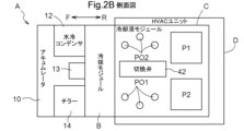
- FIG. 2 is a plan view showing the layout of a vehicle air conditioning system.
- FIG. 2 is a side view showing the layout of a vehicle air conditioning system.
- FIG. 4 is a diagram showing the flow of the coolant in a first state.
- FIG. 11 is a diagram showing the flow of the coolant in a second state.
- FIG. 4 is a diagram showing the state of a switching valve.
- the vehicle air conditioning system according to the present invention is configured to be able to cool and heat the vehicle interior.
- the vehicle air conditioning system A of this embodiment is described.
- the vehicle air conditioning system A is not limited to the following embodiment, and various modifications are possible without departing from the gist of the system.
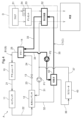
- FIG. 1 shows the circuit configuration of vehicle air conditioning system A.
- Vehicle air conditioning system A is mounted on a vehicle, and as shown in Figure 1, comprises a refrigerant module B, a coolant module C, and an HVAC (Heating, Ventilation, and Air Conditioning) unit D (an example of an "air conditioning unit").
- a refrigerant flow path B1 is provided in the refrigerant module B, which is configured as a refrigerant manifold.
- a coolant flow path C1 is provided in the coolant module C, which is configured as a coolant manifold.
- the manifold is a flow path housing in which a plate member is laminated and sealed on a housing main body in which the coolant flow path C1 and the refrigerant flow path B1 are engraved.
- the flow path housing is formed from a metal material with high thermal conductivity, including aluminum.
- Refrigerant such as hydrofluorocarbon (HFC) or hydrofluoroolefin (HFO) flows through refrigerant flow path B1, and coolant flow path C1 is made of cooling water such as antifreeze or long-life coolant mainly composed of ethylene glycol, or insulating oil such as paraffin.
- 2A and 2B show the arrangement of refrigerant module B, coolant module C, and HVAC unit D in vehicle air conditioning system A. 2A is a plan view, and 2B is a side view.
- the front side in the traveling direction of the vehicle when vehicle air conditioning system A is mounted on the vehicle is shown as F, and the rear side in the traveling direction is shown as R.
- Coolant module C is provided with ports PO1 and PO2 through which coolant is introduced and discharged.
- refrigerant flow path B1 circulates refrigerant between the water-cooled condenser (an example of a "condenser") 12 and the chiller (an example of an "evaporator") 14.
- Refrigerant module B is configured to allow refrigerant to flow between the accumulator 10, the compressor 11, the water-cooled condenser 12, the expansion valve 13, and the chiller 14 via the refrigerant flow path B1.
- the accumulator 10 stores liquid refrigerant and separates the stored refrigerant into gas and liquid.
- the gas refrigerant separated by the accumulator 10 flows through the first refrigerant path 21 and is sent to the compressor 11.
- the compressor 11 compresses the refrigerant from the accumulator 10. This causes the refrigerant to become a high-temperature compressed gas.
- the compressor 11 sends this high-temperature compressed gas to the water-cooled condenser 12 via the second refrigerant path 22.
- the compressor 11 pressure-feeds the refrigerant from the accumulator 10 to the water-cooled condenser 12.
- the water-cooled condenser 12 is circulated with the refrigerant that has passed through the compressor 11.
- the water-cooled condenser 12 is configured so that the refrigerant flows in from the first cooling liquid flow path 31 and flows out from the second cooling liquid flow path 32.
- the first cooling liquid flow path 31 and the second cooling liquid flow path 32 are configured separately from the second refrigerant path 22.
- the refrigerant from the second refrigerant path 22 is condensed and liquefied as heat is absorbed by the cooling liquid.
- the liquefied refrigerant is sent to the third refrigerant path 23.
- This third refrigerant path 23 is also configured separately from the first cooling liquid flow path 31 and the second cooling liquid flow path 32, like the second refrigerant path 22.
- the refrigerant (liquefied refrigerant) flowing through the third refrigerant passage 23 is expanded and turned into a low-temperature, low-pressure mist.
- the mist-like refrigerant is sent to the fourth refrigerant passage 24.
- the refrigerant flows through the chiller 14 via the fourth refrigerant passage 24.
- the refrigerant expanded by the expansion valve 13 and turned into a low-temperature, low-pressure mist flows through the fourth refrigerant passage 24, and this refrigerant is sent to the chiller 14.
- the chiller 14 is configured such that the coolant that has undergone heat exchange in the heat exchanger 52 flows into it from the third coolant passage 33, and the coolant flows out from the fourth coolant passage 34.
- the third coolant passage 33 and the fourth coolant passage 34 are configured separately from the fourth refrigerant passage 24.
- the mist-like refrigerant removes heat from the coolant and evaporates.
- the evaporated refrigerant flows to the accumulator 10 through the fifth refrigerant passage 25.
- the cooling liquid flow path C1 also carries the cooling liquid that exchanges heat with the refrigerant in the water-cooled condenser 12 and the chiller 14.
- the cooling liquid module C is configured to allow the cooling liquid to flow through the cooling liquid flow path C1 between the water-cooled condenser 12, the chiller 14, the switching valve 42, the radiator 43, and the heat exchanger 52 by the first pump P1 and the second pump P2.
- the water-cooled condenser 12 is configured so that the coolant flows in through the first coolant flow path 31 and flows out through the second coolant flow path 32.
- the first coolant flow path 31 is provided with a first pump P1, which pumps out the coolant.
- the switching valve 42 is disposed in the cooling liquid flow path C1, and is configured to allow the flow of cooling liquid from the water-cooled condenser 12 and the chiller 14. Cooling liquid is sent from the water-cooled condenser 12 via the second cooling liquid flow path 32 to the switching valve 42, and cooling liquid is sent from the chiller 14 via the fourth cooling liquid flow path 34.
- a second pump P2 is provided in the fourth cooling liquid flow path 34, and the second pump P2 sends cooling liquid from the chiller 14 to the switching valve 42.
- the switching valve 42 is configured to be able to send the cooling liquid to the fifth cooling liquid flow path 35 and the sixth cooling liquid flow path 36.
- the cooling liquid sent from the switching valve 42 to the fifth cooling liquid flow path 35 flows through the heat exchanger 52.
- the cooling liquid sent to the heat exchanger 52 is configured to be able to be sent to the water-cooled condenser 12 via the first cooling liquid flow path 31, and is also configured to be able to be sent to the chiller 14 via the third cooling liquid flow path 33.
- the coolant sent from the switching valve 42 to the sixth coolant flow path 36 flows through the radiator 43.
- the radiator 43 heat exchange with the outside air occurs, and the coolant is cooled. After heat exchange, the coolant is sent to the first coolant flow path 31 via the seventh coolant flow path 37.
- the switching valve 42 is configured to be able to switch the flow state of the coolant in the coolant flow path C1 between a first state and a second state.
- the first state is a state in which the coolant is circulated through the water-cooled condenser 12.
- the flow state of the coolant in such a first state is shown in FIG. 3.
- the coolant is circulated by the first pump P1 through the water-cooled condenser 12, the second coolant flow path 32, the switching valve 42, the fifth coolant flow path 35, the heat exchanger 52, and the first coolant flow path 31.
- the coolant may be sent from the switching valve 42 to the sixth coolant flow path 36, and then circulated back to the first coolant flow path 31 via the radiator 43 and the seventh coolant flow path 37.
- the switching valve 42 can be switched between the first and second states by a control unit (not shown) of the vehicle air conditioning system A or a higher-level system of the vehicle air conditioning system A.
- the HVAC unit D includes a blower 51, a heat exchanger 52, a desiccant 53, and a heater (electric heater) 54.
- the blower 51 draws in outside air and sends it to the heat exchanger 52.
- the heat exchanger 52 exchanges heat between the air and the coolant to cool or heat the vehicle interior.
- the air is the outside air sucked in by the blower 51.
- the coolant is introduced into the heat exchanger 52 through the fifth coolant flow path 35 as described above, and this coolant is sent to one or both of the first coolant flow path 31 and the third coolant flow path 33 depending on the state of the switching valve 42 (details will be described later). Therefore, in the heat exchanger 52, heat exchange is performed between the outside air sent from the blower 51 and the coolant supplied through the fifth coolant flow path 35, and the air after the heat exchange is introduced into the vehicle interior. Specifically, when the outside air is cooled in the heat exchanger 52, cold air is introduced into the vehicle interior, and when the outside air is heated in the heat exchanger 52, warm air is introduced into the vehicle interior. This makes it possible to cool or heat the vehicle interior.
- the desiccant 53 adsorbs moisture contained in the moisture-containing air to generate heated dry air.
- the desiccant 53 functions as an adsorption section that adsorbs moisture, and can be constructed using an adsorbent such as zeolite, silica gel, or activated carbon.
- the desiccant 53 is provided between the blower 51 and the heat exchanger 52. Therefore, the outside air sent from the blower 51 passes through the desiccant 53 and is discharged to the heat exchanger 52.
- the electric heater 54 evaporates the moisture adsorbed in the desiccant 53 to generate cooled and humidified air.
- the electric heater 54 functions as a heating unit that evaporates the moisture adsorbed in the desiccant 53.
- the electric heater 54 is attached to the desiccant 53, for example (integrally configured with the desiccant 53). In this case, the desiccant 53 is heated by the electric heater 54, so that the moisture adsorbed in the desiccant 53 evaporates.
- the electric heater 54 may not be attached to the desiccant 53, but may be provided upstream of the desiccant 53 (between the blower 51 and the desiccant 53) and at a position separated from the desiccant 53 (it may be provided separately from the desiccant 53).
- the air from the blower 51 is heated by the electric heater 54, and the heated air is supplied to the desiccant 53, so that the moisture adsorbed in the desiccant 53 evaporates.
- the air supplied to the desiccant 53 is humidified by the moisture evaporated from the desiccant 53, producing cooled, humidified air.
- the heating section that evaporates the moisture adsorbed in the desiccant 53 may be an air heating device other than the electric heater 54.
- the desiccant 53 When moisture-containing air is supplied to the desiccant 53 from the blower 51 while the desiccant 53 does not have any moisture adsorbed therein, the desiccant 53 adsorbs the moisture in the moisture-containing air and reduces the humidity of the moisture-containing air. As a result, the moisture-containing air supplied to the desiccant 53 becomes dry air that has been dehumidified by the desiccant 53 and is discharged to the heat exchanger 52.
- the desiccant 53 desorbs the adsorbed moisture.
- the desorbed moisture humidifies the hot air.
- the hot air supplied to the desiccant 53 becomes moist air humidified by the desiccant 53 and is discharged to the heat exchanger 52.
- the heat exchanger 52 exchanges heat between the heated dry air or cooled humidified air and the coolant to generate air for cooling the vehicle interior or air for heating the vehicle interior. Therefore, the heat exchanger 52 exchanges heat between the dry air and the coolant introduced through the fifth coolant flow path 35 to generate air for cooling the vehicle interior. The heat exchanger 52 also exchanges heat between the humid air and the coolant introduced through the fifth coolant flow path 35 to generate air for heating the vehicle interior. Furthermore, the heat exchanger 52 can also exchange heat between the dry air and the coolant introduced through the fifth coolant flow path 35 to generate air for heating the vehicle interior. In this case, for example, when using the defroster function in winter, dehumidified heated air can be supplied to the vehicle interior. By introducing such air for cooling the vehicle interior or air for heating the vehicle interior into the vehicle interior, it is possible to adjust the humidity in the vehicle interior.
- the switching valve 42 is configured to allow the flow of coolant from the water-cooled condenser 12 and coolant from the chiller 14.
- the temperature of the coolant from the water-cooled condenser 12 is relatively higher than the temperature of the coolant from the chiller 14. Therefore, when heating the vehicle interior, the switching valve 42 is set to a first state in which coolant is circulated through the water-cooled condenser 12, and when cooling the vehicle interior, the switching valve 42 is set to a second state in which coolant is circulated through the chiller 14.
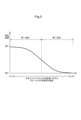
- the switching valve 42 is configured to change the opening so as to simultaneously realize the first state and the second state. Therefore, in the switching valve 42, it is possible to mix the relatively high-temperature coolant from the water-cooled condenser 12 and the relatively low-temperature coolant from the chiller 14 and send them to the fifth coolant flow path 35. As shown in FIG. 5, when the set temperature of the air conditioning in the vehicle cabin is high, the ratio of the coolant from the chiller 14 to the coolant from the water-cooled condenser 12 is reduced, and when the set temperature of the air conditioning in the vehicle cabin is low, the ratio of the coolant from the chiller 14 to the coolant from the water-cooled condenser 12 is increased.
- the opening of the switching valve 42 according to the set temperature of the air conditioning in the vehicle cabin and controlling the flow rate of the coolant from the second coolant flow path 32 and the flow rate of the coolant from the fourth coolant flow path 34, the temperature of the coolant sent to the fifth coolant flow path 35 is adjusted, and the temperature in the vehicle cabin can be adjusted to the set temperature of the air conditioning.
- the refrigerant module B and the coolant module C are integrated with the HVAC unit D.
- integration means that the refrigerant module B and the coolant module C are fixed to the HVAC unit D with bolts or the like.
- This "integration” also includes forming the same case by combining the materials of the HVAC unit D, the refrigerant module B, and the coolant module C.
- the refrigerant module B is provided on the front side of the HVAC unit D in the direction of travel of the vehicle.
- the vehicle air conditioning system A can be made smaller, and power consumption can be improved.
- the water-cooled condenser 12, the expansion valve 13, and the chiller 14 can be disposed in the front of the vehicle, so that the wind generated by the vehicle can be blown onto the water-cooled condenser 12, the expansion valve 13, and the chiller 14 as the vehicle travels. This makes it possible to prevent condensation on the water-cooled condenser 12, the expansion valve 13, and the chiller 14.
- the coolant module C is provided on the left side of the vehicle in the HVAC unit D. This makes it possible to easily secure the introduction and discharge routes of the coolant in the coolant module C by providing ports PO1 and PO2 as shown in FIG. 2B. Also, the first pump P1, the second pump P2, and the switching valve 42 can be arranged on the side of the HVAC unit D, improving maintainability.
- the refrigerant module B is described as being integrated with the HVAC unit D. However, it is also possible for the refrigerant module B to be provided separately (independently) from the HVAC unit D, without being integrated with the HVAC unit D.
- the refrigerant module B is provided on the front side of the HVAC unit D in the direction of travel of the vehicle.
- the refrigerant module B may be provided on the rear side of the HVAC unit D in the direction of travel of the vehicle, or the refrigerant module B may be provided on the left or right side of the HVAC unit D.
- the coolant module C is described as being provided on the left side of the vehicle in the HVAC unit D when the HVAC unit D is mounted on the vehicle.
- the coolant module C may be provided on the right side of the vehicle in the HVAC unit D, or may be provided on the front or rear side in the direction of travel of the vehicle.
- the water-cooled condenser 12 and chiller 14 are shown as being provided separately from the HVAC unit D.
- the water-cooled condenser 12 and chiller 14 may be provided in the HVAC unit D.
- the routing of the flow path for circulating the cooling liquid from the water-cooled condenser 12 to the HVAC unit D and the flow path for circulating the cooling liquid from the chiller 14 to the HVAC unit D can be made even easier and shorter.
- the vehicle air conditioning system A includes a coolant module C having a coolant flow path C1 through which coolant that exchanges heat with the refrigerant in a water-cooled condenser 12 (condenser) and a chiller 14 (evaporator) flows, and an HVAC unit D (air conditioning unit) that cools and heats the vehicle cabin, and the coolant module C is integrated with the HVAC unit D (air conditioning unit).
- a coolant module C having a coolant flow path C1 through which coolant that exchanges heat with the refrigerant in a water-cooled condenser 12 (condenser) and a chiller 14 (evaporator) flows
- an HVAC unit D air conditioning unit
- the coolant module C is integrated with the HVAC unit D, so compared to when the coolant module C is not integrated with the HVAC unit D, the routing of the flow paths for circulating the coolant from the water-cooled condenser 12 to the HVAC unit D and the flow paths for circulating the coolant from the chiller 14 to the HVAC unit D can be simplified and shortened. As a result, heat dissipation from the coolant flowing through the flow paths can be suppressed, making it possible to improve power consumption.
- the vehicle air conditioning system A can be made smaller, making it possible to expand the cabin space.
- the vehicle air conditioning system A described in (1) further includes a refrigerant module B having a refrigerant flow path B1 that circulates refrigerant between the water-cooled condenser 12 and the chiller 14, and it is preferable that the refrigerant module B is integrated with the HVAC unit D.
- the refrigerant module B is integrated with the HVAC unit D, so the routing of the flow paths through which the coolant flows between the refrigerant module B and the HVAC unit D and the coolant module C can be made easier and shorter than when the refrigerant module B is not integrated with the HVAC unit D.
- This allows the vehicle air conditioning system A to be further miniaturized, making it possible to improve power consumption.
- the vehicle air conditioning system A includes a refrigerant module B having a refrigerant flow path B1 that circulates the refrigerant between the water-cooled condenser 12 and the chiller 14, and an HVAC unit D that cools and heats the vehicle cabin, and the refrigerant module B is integrated with the HVAC unit D.
- the refrigerant module B is provided on the front side of the HVAC unit D in the direction of travel of the vehicle.
- the refrigerant module B is provided with a water-cooled condenser 12 and chiller 14, and the water-cooled condenser 12 and chiller 14 can be positioned at the front of the vehicle, making it possible to blow the wind from the vehicle onto the water-cooled condenser 12 and chiller 14 as the vehicle travels. This makes it possible to prevent condensation on the water-cooled condenser 12 and chiller 14.
- the coolant module C is provided on the surface of the HVAC unit D that is perpendicular to the vehicle's traveling direction.
- This configuration makes it easy to ensure the introduction and discharge routes of the coolant in the coolant module C.
- a pump for circulating the coolant can be placed on the side of the HVAC unit D, which improves maintainability.
- the HVAC unit D has a heat exchanger 52.
- This configuration makes it easier and shorter to route the flow paths that carry the cooling liquid from the water-cooled condenser 12 to the HVAC unit D, and the flow paths that carry the cooling liquid from the chiller 14 to the HVAC unit D.
- the coolant module C is integrated with the HVAC unit D by being fixed with bolts, or is housed in the same case as the HVAC unit D and integrated.
- the coolant module C and the HVAC unit D are integrated, making it easy to install in the vehicle.
- the refrigerant module B is integrated with the HVAC unit D by being fixed with bolts, or is housed in the same case as the HVAC unit D and integrated.
- This configuration makes it easier and shorter to route the flow path that circulates the refrigerant from the water-cooled condenser 12 to the HVAC unit D, and the flow path that circulates the refrigerant from the chiller 14 to the HVAC unit D.
- This configuration makes it possible to blow air from the vehicle onto the water-cooled condenser 12 and chiller 14 as the vehicle moves. This makes it possible to prevent condensation on the water-cooled condenser 12 and chiller 14.
- the technology disclosed herein can be used in vehicle air conditioning systems.
Landscapes
- Physics & Mathematics (AREA)
- Thermal Sciences (AREA)
- Engineering & Computer Science (AREA)
- Mechanical Engineering (AREA)
- Air-Conditioning For Vehicles (AREA)
Priority Applications (3)
| Application Number | Priority Date | Filing Date | Title |
|---|---|---|---|
| EP24823060.9A EP4674653A1 (en) | 2023-06-13 | 2024-03-28 | Vehicle air-conditioning system |
| JP2025527476A JPWO2024257437A1 (https=) | 2023-06-13 | 2024-03-28 | |
| CN202480034937.2A CN121194888A (zh) | 2023-06-13 | 2024-03-28 | 车辆空调系统 |
Applications Claiming Priority (2)
| Application Number | Priority Date | Filing Date | Title |
|---|---|---|---|
| JP2023097056 | 2023-06-13 | ||
| JP2023-097056 | 2023-06-13 |
Publications (1)
| Publication Number | Publication Date |
|---|---|
| WO2024257437A1 true WO2024257437A1 (ja) | 2024-12-19 |
Family
ID=93851858
Family Applications (1)
| Application Number | Title | Priority Date | Filing Date |
|---|---|---|---|
| PCT/JP2024/012730 Ceased WO2024257437A1 (ja) | 2023-06-13 | 2024-03-28 | 車両空調システム |
Country Status (4)
| Country | Link |
|---|---|
| EP (1) | EP4674653A1 (https=) |
| JP (1) | JPWO2024257437A1 (https=) |
| CN (1) | CN121194888A (https=) |
| WO (1) | WO2024257437A1 (https=) |
Citations (5)
| Publication number | Priority date | Publication date | Assignee | Title |
|---|---|---|---|---|
| WO2014156585A1 (ja) * | 2013-03-29 | 2014-10-02 | 本田技研工業株式会社 | 車両用空調装置 |
| JP2015182487A (ja) * | 2014-03-20 | 2015-10-22 | カルソニックカンセイ株式会社 | 車両用空調装置 |
| JP2016107931A (ja) * | 2014-12-10 | 2016-06-20 | 株式会社デンソー | 車両用空調装置 |
| US20190039440A1 (en) * | 2017-08-04 | 2019-02-07 | Tesla, Inc. | Technologies for manifolds |
| JP2019060580A (ja) | 2017-09-28 | 2019-04-18 | 株式会社デンソー | 冷凍サイクル装置 |
-
2024
- 2024-03-28 JP JP2025527476A patent/JPWO2024257437A1/ja active Pending
- 2024-03-28 WO PCT/JP2024/012730 patent/WO2024257437A1/ja not_active Ceased
- 2024-03-28 CN CN202480034937.2A patent/CN121194888A/zh active Pending
- 2024-03-28 EP EP24823060.9A patent/EP4674653A1/en active Pending
Patent Citations (5)
| Publication number | Priority date | Publication date | Assignee | Title |
|---|---|---|---|---|
| WO2014156585A1 (ja) * | 2013-03-29 | 2014-10-02 | 本田技研工業株式会社 | 車両用空調装置 |
| JP2015182487A (ja) * | 2014-03-20 | 2015-10-22 | カルソニックカンセイ株式会社 | 車両用空調装置 |
| JP2016107931A (ja) * | 2014-12-10 | 2016-06-20 | 株式会社デンソー | 車両用空調装置 |
| US20190039440A1 (en) * | 2017-08-04 | 2019-02-07 | Tesla, Inc. | Technologies for manifolds |
| JP2019060580A (ja) | 2017-09-28 | 2019-04-18 | 株式会社デンソー | 冷凍サイクル装置 |
Non-Patent Citations (1)
| Title |
|---|
| See also references of EP4674653A1 |
Also Published As
| Publication number | Publication date |
|---|---|
| EP4674653A1 (en) | 2026-01-07 |
| CN121194888A (zh) | 2025-12-23 |
| JPWO2024257437A1 (https=) | 2024-12-19 |
Similar Documents
| Publication | Publication Date | Title |
|---|---|---|
| JP7243410B2 (ja) | 車両用電池加熱装置 | |
| CN104995047B (zh) | 车辆用空调装置 | |
| AU2008263367B2 (en) | Humidity controller | |
| JPWO2014065255A1 (ja) | バッテリ温度調整ユニット及びこれを搭載した車両 | |
| JP2024178706A (ja) | 車両空調システム | |
| WO2015046194A1 (ja) | 車両用空調装置、電動圧縮機、及び車両の空調方法 | |
| JP4265067B2 (ja) | 乗物用空調装置 | |
| JP3959829B2 (ja) | 冷凍装置および空調装置 | |
| WO2022163712A1 (ja) | 温度制御システム | |
| JP2017043309A (ja) | 車両用空気調和装置 | |
| WO2024257437A1 (ja) | 車両空調システム | |
| KR20220157067A (ko) | 차량용 히트펌프 시스템 | |
| JPH1163719A (ja) | 冷凍装置 | |
| JP2001030743A (ja) | 電気自動車用ヒートポンプ式空気調和装置 | |
| WO2020246306A1 (ja) | 車両用空気調和装置 | |
| JP2001354029A (ja) | ヒートポンプ式車両用空調装置 | |
| WO2024257451A1 (ja) | 車両空調システム | |
| JP7097345B2 (ja) | 車両用空調装置 | |
| CN115139742A (zh) | 热泵空调系统及车辆 | |
| JP2018070027A (ja) | 蓄熱装置 | |
| CN118991374B (zh) | 车辆及其热管理系统 | |
| WO2020241612A1 (ja) | 車両用空気調和装置 | |
| JP6319275B2 (ja) | 吸着式ヒートポンプを備えた車両用エアコン装置 | |
| JP2025030645A (ja) | 車両空調システム | |
| JP2025030479A (ja) | 車両空調システム |
Legal Events
| Date | Code | Title | Description |
|---|---|---|---|
| 121 | Ep: the epo has been informed by wipo that ep was designated in this application |
Ref document number: 24823060 Country of ref document: EP Kind code of ref document: A1 |
|
| WWE | Wipo information: entry into national phase |
Ref document number: 2024823060 Country of ref document: EP |
|
| ENP | Entry into the national phase |
Ref document number: 2025527476 Country of ref document: JP Kind code of ref document: A |
|
| WWE | Wipo information: entry into national phase |
Ref document number: 2025527476 Country of ref document: JP |
|
| ENP | Entry into the national phase |
Ref document number: 2024823060 Country of ref document: EP Effective date: 20250929 |
|
| ENP | Entry into the national phase |
Ref document number: 2024823060 Country of ref document: EP Effective date: 20250929 |
|
| ENP | Entry into the national phase |
Ref document number: 2024823060 Country of ref document: EP Effective date: 20250929 |
|
| WWP | Wipo information: published in national office |
Ref document number: 2024823060 Country of ref document: EP |
|
| NENP | Non-entry into the national phase |
Ref country code: DE |