WO2024257367A1 - 医療用ワイヤ - Google Patents
医療用ワイヤ Download PDFInfo
- Publication number
- WO2024257367A1 WO2024257367A1 PCT/JP2023/036564 JP2023036564W WO2024257367A1 WO 2024257367 A1 WO2024257367 A1 WO 2024257367A1 JP 2023036564 W JP2023036564 W JP 2023036564W WO 2024257367 A1 WO2024257367 A1 WO 2024257367A1
- Authority
- WO
- WIPO (PCT)
- Prior art keywords
- flexible tube
- wire
- tubular body
- flexible
- flexible tubular
- Prior art date
- Legal status (The legal status is an assumption and is not a legal conclusion. Google has not performed a legal analysis and makes no representation as to the accuracy of the status listed.)
- Ceased
Links
Images

Classifications
-
- A—HUMAN NECESSITIES
- A61—MEDICAL OR VETERINARY SCIENCE; HYGIENE
- A61M—DEVICES FOR INTRODUCING MEDIA INTO, OR ONTO, THE BODY; DEVICES FOR TRANSDUCING BODY MEDIA OR FOR TAKING MEDIA FROM THE BODY; DEVICES FOR PRODUCING OR ENDING SLEEP OR STUPOR
- A61M25/00—Catheters; Hollow probes
- A61M25/0043—Catheters; Hollow probes characterised by structural features
- A61M25/0054—Catheters; Hollow probes characterised by structural features with regions for increasing flexibility
-
- A—HUMAN NECESSITIES
- A61—MEDICAL OR VETERINARY SCIENCE; HYGIENE
- A61M—DEVICES FOR INTRODUCING MEDIA INTO, OR ONTO, THE BODY; DEVICES FOR TRANSDUCING BODY MEDIA OR FOR TAKING MEDIA FROM THE BODY; DEVICES FOR PRODUCING OR ENDING SLEEP OR STUPOR
- A61M25/00—Catheters; Hollow probes
- A61M25/01—Introducing, guiding, advancing, emplacing or holding catheters
- A61M25/0105—Steering means as part of the catheter or advancing means; Markers for positioning
- A61M25/0133—Tip steering devices
-
- A—HUMAN NECESSITIES
- A61—MEDICAL OR VETERINARY SCIENCE; HYGIENE
- A61M—DEVICES FOR INTRODUCING MEDIA INTO, OR ONTO, THE BODY; DEVICES FOR TRANSDUCING BODY MEDIA OR FOR TAKING MEDIA FROM THE BODY; DEVICES FOR PRODUCING OR ENDING SLEEP OR STUPOR
- A61M25/00—Catheters; Hollow probes
- A61M25/01—Introducing, guiding, advancing, emplacing or holding catheters
- A61M25/09—Guide wires
-
- A—HUMAN NECESSITIES
- A61—MEDICAL OR VETERINARY SCIENCE; HYGIENE
- A61M—DEVICES FOR INTRODUCING MEDIA INTO, OR ONTO, THE BODY; DEVICES FOR TRANSDUCING BODY MEDIA OR FOR TAKING MEDIA FROM THE BODY; DEVICES FOR PRODUCING OR ENDING SLEEP OR STUPOR
- A61M25/00—Catheters; Hollow probes
- A61M2025/0004—Catheters; Hollow probes having two or more concentrically arranged tubes for forming a concentric catheter system
-
- A—HUMAN NECESSITIES
- A61—MEDICAL OR VETERINARY SCIENCE; HYGIENE
- A61M—DEVICES FOR INTRODUCING MEDIA INTO, OR ONTO, THE BODY; DEVICES FOR TRANSDUCING BODY MEDIA OR FOR TAKING MEDIA FROM THE BODY; DEVICES FOR PRODUCING OR ENDING SLEEP OR STUPOR
- A61M25/00—Catheters; Hollow probes
- A61M25/01—Introducing, guiding, advancing, emplacing or holding catheters
- A61M25/0105—Steering means as part of the catheter or advancing means; Markers for positioning
- A61M25/0133—Tip steering devices
- A61M25/0147—Tip steering devices with movable mechanical means, e.g. pull wires
- A61M2025/015—Details of the distal fixation of the movable mechanical means
-
- A—HUMAN NECESSITIES
- A61—MEDICAL OR VETERINARY SCIENCE; HYGIENE
- A61M—DEVICES FOR INTRODUCING MEDIA INTO, OR ONTO, THE BODY; DEVICES FOR TRANSDUCING BODY MEDIA OR FOR TAKING MEDIA FROM THE BODY; DEVICES FOR PRODUCING OR ENDING SLEEP OR STUPOR
- A61M25/00—Catheters; Hollow probes
- A61M25/01—Introducing, guiding, advancing, emplacing or holding catheters
- A61M25/09—Guide wires
- A61M2025/09058—Basic structures of guide wires
- A61M2025/09066—Basic structures of guide wires having a coil without a core possibly combined with a sheath
Definitions
- the present invention relates to a medical wire such as a guidewire.
- a medical wire such as a guidewire.
- a guidewire including a first flexible tubular body (outer flexible tubular body 4) extending in the front-rear direction and formed to be bendable, an operating wire (core shaft) extending in the front-rear direction and inserted inside the first flexible tubular body, and a support fixed to the rear end of the first flexible tubular body, as shown in, for example, the following Patent Document 1.
- a guidewire is inserted into a blood vessel and used to guide a balloon or a stent to a chronic totally occluded lesion or the like in a state where the guidewire penetrates a chronic totally occluded lesion or the like in the blood vessel.
- the guidewire (first guidewire) is advanced into the blood vessel while being inserted into the microcatheter, and reaches the chronic total occlusion lesion or the like in the blood vessel.
- the microcatheter is left in the blood vessel, and the guidewire (first guidewire) that has been used up until now is pulled out.
- a guidewire (second guidewire) with a higher tip load than the guidewire (first guidewire) is inserted into the microcatheter again and pierces the chronic total occlusion lesion or the like, and the chronic total occlusion lesion or the like is penetrated by the guidewire (second guidewire) and the microcatheter.
- the guidewire (second guidewire) with a higher tip load or the like is pulled out while the microcatheter is left in the blood vessel while penetrating the chronic total occlusion lesion or the like, and the original guidewire (first guidewire) with a lower tip load or the like is inserted again into the microcatheter.
- the microcatheter is pulled out while the guidewire (first guidewire) is left in the blood vessel.
- the present invention provides a medical wire that can shorten surgery time.
- a medical wire includes a first flexible tube extending in the front-rear direction and formed to be bendable, a control wire extending in the front-rear direction and inserted inside the first flexible tube, and a support fixed to the rear end of the first flexible tube, and the front end of the control wire is fixed to the front end of the first flexible tube in a state spaced apart from the central axis of the first flexible tube in one of the radial directions.
- the front end of the manipulation wire is fixed to the front end of the first flexible tubular body in a state spaced apart from the central axis of the first flexible tubular body in one radial direction. Therefore, when the manipulation wire is pulled backward, the first flexible tubular body is compressed and deformed while bending in one specific radial direction. This allows the medical wire to enter a target blood vessel by selecting a blood vessel at a blood vessel branch while bending the front end of the medical wire in a specific direction by manipulating the manipulation wire.
- the bending rigidity of the first flexible tubular body is kept low until the medical wire enters a blood vessel and reaches a chronic total occlusion lesion or the like in the blood vessel, and when the medical wire is thrust into a chronic total occlusion lesion or the like and penetrates the chronic total occlusion lesion or the like with the medical wire, the manipulation wire is pulled backward to increase the bending rigidity of the first flexible tubular body, and after penetration of the chronic total occlusion lesion or the like, the manipulation of the manipulation wire is released to return the bending rigidity of the first flexible tubular body to its original low state.
- the bending stiffness of the intermediate portion of the first flexible tube, located between the front end and the rear end, may decrease from the rear to the front.
- the bending stiffness of the intermediate portion of the first flexible tube, located between the front and rear ends, decreases from the rear to the front. Therefore, by manipulating the control wire, it is possible to precisely bend only the front end of the medical wire in a specific direction, and the medical wire can be easily inserted into the target blood vessel by selecting the blood vessel at the vascular branch point.
- the device further includes a second flexible tube inserted inside the first flexible tube, extending in the front-rear direction and formed to be bendable and deformable, the operation wire is inserted inside the second flexible tube, the central axis of the second flexible tube and the front end of the operation wire are spaced apart from the central axis of the first flexible tube in one radial direction, the front end of the second flexible tube is fixed to at least one of the front end of the first flexible tube and the front end of the operation wire, and the rear end of the second flexible tube located rearward of the front end is fixed to at least one of the support body and the rear end of the first flexible tube.
- a second flexible tube is provided. Therefore, when the operating wire is pulled backward, the first flexible tube and the second flexible tube are compressed and deformed while bending in one radial direction. This makes it possible to easily adjust (design) the relationship between the operating force on the operating wire and the bending shape of the front end of the medical wire, for example, while maintaining the outer diameter of the medical wire.
- the bending stiffness of the intermediate portion of the second flexible tube, located between the front end and the rear end, may decrease from the rear to the front.
- the bending stiffness of the middle section of the second flexible tube, located between the front end and rear end, decreases from the rear to the front, so that by manipulating the operating wire, only the front end of the medical wire can be bent with precision in a specific direction.
- At least one of the first flexible tube and the second flexible tube is a coil spring extending in the front-rear direction. Therefore, it is easy to obtain a medical wire whose front end can be bent in a specific direction when the operating wire is pulled backward.
- the device may further include an operating unit provided behind the support, to which the operating wire is fixed and which is movable in the forward and backward directions relative to the support.
- An operating section to which the operating wire is fixed is provided behind the support. This improves the operability of the medical wire compared to when the operating wire is directly operated.
- the above aspects of the present invention can shorten the surgery time.
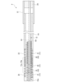
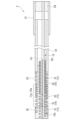
- FIG. 1 is a longitudinal sectional view of a medical wire according to a first embodiment.
- FIG. FIG. 11 is a longitudinal sectional view of a medical wire according to a second embodiment.
- FIG. 11 is a longitudinal sectional view of a medical wire according to a third embodiment.
- the medical wire 1 is a guide wire including a first flexible tubular body 11, an operation wire 12, an operation section 13, and a support 14.
- the first flexible tubular body 11, the operation wire 12, the operation section 13, and the support 14 are formed of, for example, a metal material. Note that the materials forming the first flexible tubular body 11, the operation wire 12, the operation section 13, and the support 14 may be changed as appropriate.
- the operation section 13 does not have to be provided.
- the operation portion 13 and the support body 14 are formed in a cylindrical shape and are disposed coaxially with the central axis O ⁇ b>1 of the first flexible tubular body 11 .
- the side where the first flexible tube 11 is located with respect to the support 14 in the direction in which the central axis O1 extends will be referred to as the front side
- the side where the operation unit 13 is located with respect to the support 14 in the direction in which the central axis O1 extends will be referred to as the rear side
- the direction in which the central axis O1 extends will be referred to as the front-rear direction.
- a direction that intersects with the central axis O1 as viewed from the front-rear direction will be referred to as the radial direction, and a direction that rotates around the central axis O1 as viewed from the front-rear direction will be referred to as the circumferential direction.
- the first flexible tubular body 11 extends in the front-rear direction and is formed to be bendable and deformable.
- the first flexible tubular body 11 is a coil spring that extends in the front-rear direction.
- the outer diameter of the first flexible tubular body 11 is large enough to be inserted into a blood vessel (e.g., 0.2 mm to 1.0 mm).
- the outer shape and size of the first flexible tubular body 11 as viewed from the front-rear direction are the same over the entire length in the front-rear direction.
- the diameter of the wire material forming the first flexible tubular body 11 is the same over the entire length.
- the diameter of the wire forming the first flexible tube 11 does not have to be the same along its entire length. Furthermore, the outer shape and size of the first flexible tube 11 as viewed from the front-to-rear direction do not have to be the same along its entire length in the front-to-rear direction. For example, the outer diameter of the first flexible tube 11 may become smaller toward the front.
- the first flexible tube 11 is not limited to a coil spring, and may be, for example, a tube having a peripheral wall that extends continuously along its entire length in both the front-to-rear and circumferential directions.
- the support 14 is fixed to the rear end of the first flexible tube 11.
- the support 14 extends in the front-rear direction and is formed to be capable of bending and deforming.
- the rear end opening edge of the first flexible tube 11 abuts against the front end opening edge of the support 14 in the front-rear direction.
- the front end of the support 14 and the rear end of the first flexible tube 11 are fixed by, for example, soldering, brazing, adhesive, or crimping.
- a cylindrical intermediate fixing member 23 made of, for example, solder, brazing material, or adhesive extends forward from the front opening edge of the support 14.
- the thickness of the intermediate fixing member 23 is equal to the diameter of the wire material forming the first flexible tube 11, which is a coil spring. With the rear opening of the first flexible tube 11 open, the rear end of the first flexible tube 11 is embedded in the intermediate fixing member 23.
- the outer peripheral surface of the intermediate fixing member 23 is connected to the outer peripheral surface of the support 14 and the outer peripheral surface of the first flexible tube 11 without any steps in the front-rear direction, and the inner peripheral surface of the intermediate fixing member 23 is connected to the inner peripheral surface of the support 14 and the inner peripheral surface of the first flexible tube 11 without any steps in the front-rear direction.
- the outer diameter of the support 14 is equal to the outer diameter of the first flexible tubular body 11 and is of a size that allows it to be inserted into a blood vessel (e.g., 0.2 mm to 1.0 mm).
- the outer shape and size of the support 14 as viewed in the front-rear direction are the same over the entire length in the front-rear direction.
- the outer shape and size of the support 14 as viewed from the front-rear direction do not have to be the same over the entire length in the front-rear direction. For example, the outer diameter of the support 14 may become smaller toward the front.
- the outer shapes and sizes of the support 14 and the first flexible tubular body 11 as viewed from the front-rear direction may be different from each other. In this case, it is preferable that the support 14 does not protrude radially outward from the outer circumferential surface of the first flexible tubular body 11 as viewed from the front-rear direction.
- the operation unit 13 is provided behind the support body 14.
- the operation unit 13 protrudes rearward from the support body 14.
- the operation unit 13 is provided so as to be movable in the front-rear direction relative to the support body 14.
- the rear end of the support body 14 is inserted into the front part of the operation unit 13.
- the front end opening edge of the operating unit 13 and the rear end opening edge of the support body 14 may face each other in the front-to-rear direction, and the front part of the operating unit 13 may be inserted into the rear end part of the support body 14.
- the rear portion of the operation wire 12 is fixed to the operation unit 13 by, for example, soldering, brazing, adhesion, crimping, etc.
- the rear end opening of the operation unit 13 is closed by a rear fixing member 24 made of, for example, a solder material, a brazing material, an adhesive, etc., and the rear portion of the operation wire 12 is embedded in the rear fixing member 24.
- the operation wire 12 extends in the front-rear direction and is inserted inside the first flexible tubular body 11.
- the operation wire 12 is formed to be elastically deformable.
- a front end of the operation wire 12 is fixed to a front end of the first flexible tubular body 11 by, for example, soldering, brazing, bonding, or crimping in a state separated from the central axis O1 in one radial direction.
- a plurality of operation wires 12 may be provided at intervals in the circumferential direction.
- the operation wire 12 extends straight in the front-rear direction.
- the operation wire 12 may extend in the front-rear direction while being bent, for example.
- the operation wire 12 is disposed on the inner circumferential surface of the first flexible tubular body 11 and the inner circumferential surface of the support body 14.
- the rear part of the operation wire 12 protrudes rearward from the support body 14.
- the protruding part 12a protruding forward from the first flexible tubular body 11 is bent in one radial direction and engaged with the front end opening edge of the first flexible tubular body 11.
- the protruding part 12a of the operation wire 12 is located at the same radial position or radially inward with respect to the outer circumferential surface of the front end part of the first flexible tubular body 11.
- the tip surface of the operation wire 12 faces in one radial direction.
- the front end opening of the first flexible tube 11 is closed by a front fixing member 25 made of, for example, a solder material, a brazing material, or an adhesive.
- the outer peripheral surface of the front fixing member 25 is connected to the outer peripheral surface of the first flexible tube 11 without any step in the front-to-rear direction.
- the front end of the operating wire 12, including the protruding portion 12a, is embedded in the front fixing member 25.
- the bending rigidity of an intermediate portion 11a located between the front end portion (front fixing member 25) and the rear end portion (middle fixing member 23) decreases from the rear to the front.
- the first flexible tube 11 includes a first hard tube section 22 having high bending rigidity, and a pair of first soft tube sections 21 having lower bending rigidity than the first hard tube section 22 and sandwiching the first hard tube section 22 in the front-rear direction.
- the pair of first soft tube sections 21 the number of turns of the front first soft tube section 21 located on the front side is greater than the number of turns of the rear first soft tube section 21 located on the rear side. Note that the number of turns of the front first soft tube section 21 may be less than or equal to the number of turns of the rear first soft tube section 21.
- the first soft tube section 21 is formed so that the interval (inter-wire gap) between adjacent wires in the front-rear direction is wider than that of the first hard tube section 22.
- the bending rigidity of the first soft tube section 21 is smaller than that of the first hard tube section 22, and the first soft tube section 21 flexibly bends in accordance with the bent blood vessel.
- adjacent wires in the front-rear direction are in contact with each other in the first hard tube section 22.
- the first hard tube section 22 is a tightly wound coil spring. This allows the first hard tube section 22 to flexibly bend in response to the bending deformation of the first soft tube section 21 in the intermediate section 11a of the first flexible tube 11.
- the front portion of the front first soft tube section 21 located on the front side is joined or adhered to the front fixing member 25, and the rear portion of the front first soft tube section 21 is located between the front fixing member 25 and the intermediate fixing member 23.
- the rear first soft tube section 21 located on the rear side is joined or adhered to the intermediate fixing member 23 over the entire area. Therefore, the intermediate portion 11a of the first flexible tube 11, which is located between the front fixing member 25 and the middle fixing member 23, is composed of the entire first hard tube portion 22 and the rear portion of the front first soft tube portion 21, which is located at the front side, of the pair of first soft tube portions 21.
- the bending rigidity of the intermediate portion 11a of the first flexible tube 11 decreases stepwise from the rear to the front.
- the bending rigidity of the intermediate portion 11a of the first flexible tube 11 may decrease linearly from the rear to the front.
- the length in the front-rear direction of the first hard tube section 22 is longer than the length in the front-rear direction of the rear part of the front first soft tube section 21 that is located on the front side of the pair of first soft tube sections 21.
- the length in the front-rear direction of the first hard tube section 22 may be shorter than the length in the front-rear direction of the rear part of the front first soft tube section 21.
- the front end of the operation wire 12 is fixed to the front end of the first flexible tube 11 in a state where it is spaced apart in one radial direction from the central axis O1 of the first flexible tube 11. Therefore, when the operation wire 12 is pulled backward, the first flexible tube 11 is compressed and deformed while bending in one radial direction. This allows the medical wire 1 to enter the target blood vessel by selecting a blood vessel at a blood vessel branch while bending the front end of the medical wire 1 in a desired direction by operating the operation wire 12.
- the front end of the operating wire 12 and the front end of the first flexible tube 11 move rearward, and the first flexible tube 11 undergoes compressive deformation in the front-to-rear direction between the support 14, increasing the bending rigidity of the first flexible tube 11. Therefore, by manipulating the operating wire 12 while the medical wire 1 is inserted into a blood vessel, the bending rigidity of the first flexible tube 11 can be changed.
- the bending stiffness of the first flexible tube 11 is kept low until the medical wire 1 enters a blood vessel and reaches a chronic total occlusion lesion or the like in the blood vessel, and when the medical wire 1 is pierced into a chronic total occlusion lesion or the like and penetrating the chronic total occlusion lesion or the like with the medical wire 1, the operating wire 12 is pulled backward to increase the bending stiffness of the first flexible tube 11, and after penetrating the chronic total occlusion lesion or the like, the operation of the operating wire 12 is released to return the bending stiffness of the first flexible tube 11 to its original low state. This eliminates the need to insert and remove medical wires with different bending stiffness from blood vessels or the like to penetrating a chronic total occlusion lesion or the like.
- An operating section 13 to which the operating wire 12 is fixed is provided behind the support 14. This improves the operability of the medical wire 1 compared to when the operating wire 12 is directly operated.
- a medical wire 2 according to a second embodiment of the present invention will be described with reference to FIG.
- the same components as those in the first embodiment are denoted by the same reference numerals, and their description will be omitted, with only the differences being described.
- a second flexible tube 15 extending in the front-rear direction and formed to be bendable is inserted inside the first flexible tube 11.
- a front end of the second flexible tube 15 is fixed to at least one of a front end of the first flexible tube 11 and a front end of the operation wire 12.
- a rear portion of the second flexible tube 15 located rearward of the front end is fixed to at least one of the support 14 and a rear end of the first flexible tube 11.
- the second flexible tubular body 15 protrudes in both the front-rear direction and the rear direction from the first flexible tubular body 11. Note that the second flexible tubular body 15 does not have to protrude in the front-rear direction from the first flexible tubular body 11.
- At least one of the first flexible tube 11 and the second flexible tube 15 is a coil spring extending in the front-rear direction.
- both the first flexible tube 11 and the second flexible tube 15 are coil springs extending in the front-rear direction.
- the winding directions of the first flexible tube 11 and the second flexible tube 15 are opposite to each other.
- the winding directions of the first flexible tubular body 11 and the second flexible tubular body 15 may be the same as each other.
- Either one of the first flexible tubular body 11 and the second flexible tubular body 15 is not limited to a coil spring, and may be, for example, a tubular body having a peripheral wall that extends continuously over the entire length in both the front-rear direction and the circumferential direction.
- the second flexible tube 15 In the second flexible tube 15, the bending rigidity of an intermediate portion 15a located between the front end portion (front fixing member 25) and the rear portion (middle fixing member 23) decreases from the rear to the front.
- the second flexible tube 15 is configured by connecting, from the front to the rear, a second soft tube section 31 having a low bending rigidity and a second hard tube section 32 having a higher bending rigidity than the second soft tube section 31.
- the second soft tube section 31 protrudes forward from the first flexible tube 11, and the second hard tube section 32 protrudes rearward from the first flexible tube 11.
- the length of the second soft tube section 31 in the front-rear direction is slightly shorter than the length of the second hard tube section 32 in the front-rear direction.
- the second soft tube section 31 is formed so that the interval (inter-wire gap) between adjacent wires in the front-rear direction is wider than that of the second hard tube section 32.
- the bending rigidity of the second soft tube section 31 is smaller than that of the second hard tube section 32, and the second soft tube section 31 flexibly bends in accordance with the bent blood vessel.
- adjacent wires in the front-rear direction are in contact with each other in the second hard tube section 32.
- the second hard tube section 32 is a tightly wound coil spring. This allows the second hard tube section 32 to flexibly bend in response to the bending deformation of the second soft tube section 31 in the intermediate section 15a of the second flexible tube 15.
- a front portion of the second soft tube section 31 is joined or bonded to the front fixing member 25.
- the front end portion of the second flexible tube body 15 is fixed to the front end portion of the first flexible tube body 11 and the front end portion of the operation wire 12 via the front fixing member 25.
- a rear portion of the second soft tube section 31 is located between the front fixing member 25 and the middle fixing member 23.
- An intermediate fixing member 23 is joined or bonded to the outer circumferential surface of a portion of the second hard tube section 32 located between a front end portion located inside the first flexible tube 11 and a rear end portion located inside the support body 14.
- a rear portion of the second flexible tube section 15 located rearward of the front end portion is fixed to the support body 14 and the rear end portion of the first flexible tube section 11 via the intermediate fixing member 23.
- the intermediate fixing member 23 does not close the inside of the second hard tube section 32, and the inside of the support body 14 is in communication with the inside of the rear portion of the second soft tube section 31 through the inside of the second hard tube section 32.
- the intermediate section 15a located between the front fixing member 25 and the middle fixing member 23 is composed of the rear section of the second soft tubular section 31 and the front end section of the second hard tubular section 32.
- the bending rigidity of the intermediate section 15a of the second flexible tubular body 15 decreases stepwise from the rear to the front.
- the bending rigidity of the intermediate section 15a of the second flexible tubular body 15 may decrease linearly from the rear to the front.
- the length in the front-rear direction of the rear portion of the second soft tube portion 31 is longer than the length in the front-rear direction of the front end portion of the second hard tube portion 32.
- the length in the front-rear direction of the rear portion of the second soft tube portion 31 may be equal to or shorter than the length in the front-rear direction of the front end portion of the second hard tube portion 32.
- the rear portion of the second soft tube portion 31 straddles in the front-rear direction a boundary portion between the first hard tube portion 22 and the front first soft tube portion 21 located on the front side of the pair of first soft tube portions 21, within the intermediate portion 11a of the first flexible tube body 11.
- the operation wire 12 is inserted inside the second flexible tubular body 15.
- the central axis O2 of the second flexible tubular body 15 and the front end of the operation wire 12 are spaced apart from the central axis O1 of the first flexible tubular body 11 in one radial direction.
- the front end of the operation wire 12 is fixed to the front end of the second flexible tubular body 15 by, for example, soldering, brazing, bonding, or crimping in a state spaced apart in one radial direction from the central axis O2 of the second flexible tubular body 15.
- the operation wire 12 is disposed on the inner circumferential surface of the second flexible tubular body 15.
- the protruding portion 12a of the front end of the operation wire 12 protruding forward from the second flexible tube 15 is bent in one radial direction and engaged with the front end opening edge of the second flexible tube 15.
- the protruding portion 12a of the operation wire 12 is located at the same radial position or on the inside in the radial direction with respect to the outer circumferential surface of the front end of the first flexible tube 11.
- the protruding portion 12a of the operation wire 12 is separated forward from the front end opening edge of the first flexible tube 11 and faces in the front-rear direction.
- the front fixing member 25 is also filled between the protruding portion 12a of the operation wire 12 and the front end opening edge of the first flexible tube 11, and the front end of the operation wire 12 including the protruding portion 12a is embedded in the front fixing member 25.
- the tip surface of the operation wire 12 faces in one radial direction.
- the medical wire 2 according to this embodiment has the same effect as the medical wire 1 shown in FIG. 1.
- a second flexible tube 15 is provided. Therefore, when the operating wire 12 is pulled backward, the first flexible tube 11 and the second flexible tube 15 are compressed and deformed while bending in one radial direction. This makes it possible to easily adjust (design) the relationship between the operating force on the operating wire 12 and the bending shape of the front end of the medical wire 2, for example, while maintaining the outer diameter of the medical wire 2.
- At least one of the first flexible tube 11 and the second flexible tube 15 is a coil spring that extends in the front-rear direction. Therefore, when the operating wire 12 is pulled backward, it is easy to obtain a medical wire 2 whose front end can be bent in a desired direction.
- a medical wire 3 according to a third embodiment of the present invention will be described with reference to FIG.
- the same components as those in the second embodiment are denoted by the same reference numerals, and the description thereof will be omitted, and only the differences will be described.
- the protruding portion 12a of the front end of the operating wire 12 that protrudes forward from the second flexible tube 15 is bent in one radial direction and then folded back rearward to engage with the front end opening edge of the second flexible tube 15.
- a circumferential portion of the front end of the second flexible tube 15 is radially sandwiched by the front end of the operating wire 12.
- the tip surface of the operating wire 12 faces rearward.
- the tip surface of the operating wire 12 abuts against or is close to the front end opening edge of the first flexible tube 11.
- the medical wire 3 according to this embodiment has the same effect as the medical wire 2 shown in FIG. 2.
- the bending stiffness of the intermediate portions 11a and 15a may be the same over the entire length in the front-to-rear direction.
- aspects of the present invention are as follows.
- a first flexible tube extending in the front-rear direction and formed to be bendable; an operating wire extending in a front-rear direction and inserted inside the first flexible tube; a support member fixed to a rear end portion of the first flexible tube,
- a medical wire wherein a front end of the operation wire is fixed to a front end of the first flexible tubular body in a state spaced apart in one radial direction from a central axis of the first flexible tubular body.
- ⁇ 3> a second flexible tube that is inserted inside the first flexible tube, extends in the front-rear direction, and is formed to be bendable;
- the operation wire is inserted into the second flexible tube, a central axis of the second flexible tubular body and a front end of the operation wire are spaced apart from a central axis of the first flexible tubular body in one radial direction, a front end portion of the second flexible tubular body is fixed to at least one of a front end portion of the first flexible tubular body and a front end portion of the operation wire;
- the medical wire according to ⁇ 1> or ⁇ 2>, wherein a rear portion of the second flexible tubular body, which is located rearward of the front end portion, is fixed to at least one of the support body and the rear end portion of the first flexible tubular body.
- ⁇ 4> The medical wire according to ⁇ 3>, wherein the bending rigidity of the second flexible tubular body in an intermediate portion located between the front end portion and the rear portion decreases from the rear portion to the front portion.
- ⁇ 5> The medical wire according to ⁇ 3> or ⁇ 4>, wherein at least one of the first flexible tubular body and the second flexible tubular body is a coil spring extending in a front-rear direction.
- ⁇ 6> The medical wire according to any one of ⁇ 1> to ⁇ 5>, further comprising an operation unit provided behind the support, to which the operation wire is fixed and which is movable in the front-rear direction relative to the support.
- the present invention provides a medical wire that can shorten surgery time.
- Reference Signs List 1 2, 3 Medical wire 11 First flexible tubular body 11a Middle portion of first flexible tubular body 12 Operation wire 13 Operation portion 14 Support body 15 Second flexible tubular body 15a Middle portion of second flexible tubular body O1 Central axis of first flexible tubular body O2 Central axis of second flexible tubular body
Landscapes
- Health & Medical Sciences (AREA)
- Life Sciences & Earth Sciences (AREA)
- Biophysics (AREA)
- Pulmonology (AREA)
- Engineering & Computer Science (AREA)
- Anesthesiology (AREA)
- Biomedical Technology (AREA)
- Heart & Thoracic Surgery (AREA)
- Hematology (AREA)
- Animal Behavior & Ethology (AREA)
- General Health & Medical Sciences (AREA)
- Public Health (AREA)
- Veterinary Medicine (AREA)
- Media Introduction/Drainage Providing Device (AREA)
Abstract
Description
本願は、2023年6月14日に、日本に出願された特願2023-097625号に基づき優先権を主張し、その内容をここに援用する。
ガイドワイヤにより慢性完全閉塞病変部等を貫通する際、例えば次の手順がとられている。
まず、ガイドワイヤ(第1のガイドワイヤ)を、マイクロカテーテル内に挿入した状態で血管内に進入させ、血管内の慢性完全閉塞病変部等に到達させる。マイクロカテーテルは血管内に残したまま、これまで用いていたガイドワイヤ(第1のガイドワイヤ)を抜き出し、その後、ガイドワイヤ(第1のガイドワイヤ)より先端荷重等が高いガイドワイヤ(第2のガイドワイヤ)を、改めてマイクロカテーテル内に挿入して慢性完全閉塞病変部等に突き刺し、ガイドワイヤ(第2のガイドワイヤ)およびマイクロカテーテルにより慢性完全閉塞病変部等を貫通する。その後、マイクロカテーテルは慢性完全閉塞病変部等を貫通した状態で血管内に残したまま、先端荷重等が高いガイドワイヤ(第2のガイドワイヤ)を抜き出し、先端荷重等が低い元のガイドワイヤ(第1のガイドワイヤ)を再度マイクロカテーテル内に挿入する。慢性完全閉塞病変部等を貫く位置までガイドワイヤ(第1のガイドワイヤ)を到達させた後に、ガイドワイヤ(第1のガイドワイヤ)を残したまま、マイクロカテーテルを抜き出す。
さらに、操作ワイヤを後方に引くと、操作ワイヤの前端部および第1可撓管体の前端部が後方に移動して、第1可撓管体が支持体との間で前後方向に圧縮変形することで、第1可撓管体の曲げ剛性が高くなる。したがって、医療用ワイヤを血管内に挿入した状態で、操作ワイヤを操作することで、第1可撓管体の曲げ剛性を変化させることができる。
これにより、医療用ワイヤにより慢性完全閉塞病変部等を貫通する際、医療用ワイヤを、血管内に進入させ、血管内の慢性完全閉塞病変部等に到達させるまでは、第1可撓管体の曲げ剛性を低くしておき、医療用ワイヤを慢性完全閉塞病変部等に突き刺して、医療用ワイヤにより慢性完全閉塞病変部等を貫通するときに、操作ワイヤを後方に引いて第1可撓管体の曲げ剛性を高くし、慢性完全閉塞病変部等の貫通後は、操作ワイヤの操作を解除して第1可撓管体の曲げ剛性を元の低い状態に戻すことができる。したがって、慢性完全閉塞病変部等を貫通するために、曲げ剛性の異なる医療用ワイヤを血管等に対して抜き差しして交換し使い分ける必要を無くすことができる。
以上より、手術時間を短縮させることができる。
医療用ワイヤ1は、第1可撓管体11と、操作ワイヤ12と、操作部13と、支持体14と、を備えたガイドワイヤとなっている。第1可撓管体11、操作ワイヤ12、操作部13、および支持体14は、例えば金属材料等で形成されている。なお、第1可撓管体11、操作ワイヤ12、操作部13、および支持体14を形成する材質は、適宜変更してもよい。操作部13は設けなくてもよい。
以下、中心軸線O1が延びる方向において支持体14に対して第1可撓管体11が位置している側を前側といい、中心軸線O1が延びる方向において支持体14に対して操作部13が位置している側を後側といい、中心軸線O1が延びる方向を前後方向という。前後方向から見て中心軸線O1に交差する方向を径方向といい、前後方向から見て中心軸線O1回りに周回する方向を周方向という。
第1可撓管体11の外径は、血管内に挿入可能な大きさとなっている(例えば0.2mm以上1.0mm以下)。前後方向から見た第1可撓管体11の外形形状、およびその大きさは、前後方向の全長にわたって同じになっている。第1可撓管体11を形成する線材の直径は、全長にわたって同じになっている。
なお、前後方向から見た支持体14の外形形状、およびその大きさは、前後方向の全長にわたって同じになっていなくてもよい。例えば、支持体14の外径は、前方に向かうに従い小さくなっていてもよい。前後方向から見た支持体14および第1可撓管体11それぞれの外形形状、およびその大きさを、互いに異ならせてもよい。この場合、前後方向から見て、支持体14は、第1可撓管体11の外周面から径方向の外側に張り出していないことが好ましい。
なお、操作部13の前端開口縁と、支持体14の後端開口縁と、が前後方向で対向してもよく、また、支持体14の後端部内に、操作部13の前部が挿入されてもよい。
操作部13に、操作ワイヤ12の後部が、例えばはんだ付、ろう付け、接着、若しくは加締め等によって固定されている。図示の例では、操作部13の後端開口部は、例えばはんだ材、ろう材、若しくは接着剤等からなる後固定部材24により閉塞されており、後固定部材24に操作ワイヤ12の後部が埋設されている。
なお、複数の操作ワイヤ12が、周方向に間隔をあけて設けられてもよい。
図示の例では、第1可撓管体11は、曲げ剛性の高い第1硬管部22と、第1硬管部22より曲げ剛性が低く、かつ第1硬管部22を前後方向に挟む一対の第1軟管部21と、を備えている。一対の第1軟管部21のうち、前側に位置する前側第1軟管部21の巻き数は、後側に位置する後側第1軟管部21の巻き数より多くなっている。なお、前側第1軟管部21の巻き数を、後側第1軟管部21の巻き数以下としてもよい。
図示の例では、第1硬管部22において前後方向で互いに隣り合う線材同士は互いに当接している。つまり、第1硬管部22は、密巻きのコイルばねとされている。これにより、第1可撓管体11の中間部11aにおいて、第1硬管部22は、第1軟管部21の曲げ変形に追従して柔軟に曲がることができる。
したがって、第1可撓管体11のうち、前固定部材25と中固定部材23との間に位置する中間部11aは、第1硬管部22の全体と、一対の第1軟管部21のうち、前側に位置する前側第1軟管部21の後部と、により構成されている。これにより、第1可撓管体11の中間部11aの曲げ剛性は、後方から前方に向かうに従い段階的に低くなっている。なお、第1可撓管体11の中間部11aの曲げ剛性は、後方から前方に向かうに従い線形的に低くなってもよい。
図示の例では、第1硬管部22の前後方向の長さは、一対の第1軟管部21のうち、前側に位置する前側第1軟管部21の後部の前後方向の長さより長くなっている。なお、第1硬管部22の前後方向の長さを前側第1軟管部21の後部の前後方向の長さ以下としてもよい。
なお、第2実施形態においては、第1実施形態における構成要素と同一の部分については同一の符号を付し、その説明を省略し、異なる点についてのみ説明する。
第2可撓管体15は、第1可撓管体11から前後方向の両方向に突出している。なお、第2可撓管体15は、第1可撓管体11から前後方向に突出していなくてもよい。
なお、第1可撓管体11および第2可撓管体15それぞれの巻方向は、互いに同じ向きであってもよい。第1可撓管体11および第2可撓管体15のうちのいずれか一方は、コイルばねに限らず、例えば前後方向および周方向それぞれの全長にわたって連続して延びる周壁からなる管体等であってもよい。
図示の例では、第2可撓管体15は、曲げ剛性の低い第2軟管部31と、第2軟管部31より曲げ剛性が高い第2硬管部32と、が前方から後方に向けてこの順に連ねられて構成されている。第2軟管部31が、第1可撓管体11から前方に突出し、第2硬管部32が、第1可撓管体11から後方に突出している。第2軟管部31の前後方向の長さは、第2硬管部32の前後方向の長さよりわずかに短くなっている。
図示の例では、第2硬管部32において前後方向で互いに隣り合う線材同士は互いに当接している。つまり、第2硬管部32は、密巻きのコイルばねとされている。これにより、第2可撓管体15の中間部15aにおいて、第2硬管部32は、第2軟管部31の曲げ変形に追従して柔軟に曲がることができる。
第2硬管部32のうち、第1可撓管体11内に位置する前端部と、支持体14内に位置する後端部と、の間に位置する部分の外周面に、中固定部材23が接合、若しくは接着されている。これにより、第2可撓管体15のうち、前端部より後方に位置する後部が、支持体14、および第1可撓管体11の後端部に中固定部材23を介して固定されている。図示の例では、中固定部材23が、第2硬管部32内を閉塞しておらず、支持体14内が、第2硬管部32内を通して第2軟管部31の後部内に連通している。
図示の例では、第2軟管部31の後部の前後方向の長さは、第2硬管部32の前端部の前後方向の長さより長くなっている。なお、第2軟管部31の後部の前後方向長さを第2硬管部32の前端部の前後方向の長さ以下としてもよい。第2軟管部31の後部は、第1可撓管体11の中間部11a内において、第1硬管部22と、一対の第1軟管部21のうち、前側に位置する前側第1軟管部21と、の境界部分を前後方向に跨いでいる。
操作ワイヤ12の前端部は、第2可撓管体15の中心軸線O2から径方向のうちの一方向に離れた状態で、第2可撓管体15の前端部に、例えばはんだ付、ろう付け、接着、若しくは加締め等によって固定されている。操作ワイヤ12は、第2可撓管体15の内周面上に配置されている。
なお、第3実施形態においては、第2実施形態における構成要素と同一の部分については同一の符号を付し、その説明を省略し、異なる点についてのみ説明する。
<1>
前後方向に延びるとともに、曲げ変形可能に形成された第1可撓管体と、
前後方向に延びるとともに、前記第1可撓管体の内側に挿入された操作ワイヤと、
前記第1可撓管体の後端部に固定された支持体と、を備え、
前記操作ワイヤの前端部は、前記第1可撓管体の中心軸線から径方向のうちの一方向に離れた状態で、前記第1可撓管体の前端部に固定されている、医療用ワイヤ。
<2>
前記第1可撓管体のうち、前端部と後端部との間に位置する中間部の曲げ剛性は、後方から前方に向かうに従い低くなっている、前記<1>に記載の医療用ワイヤ。
<3>
前記第1可撓管体の内側に挿入され、前後方向に延びるとともに、曲げ変形可能に形成された第2可撓管体、をさらに備え、
前記第2可撓管体の内側に、前記操作ワイヤが挿入され、
前記第2可撓管体の中心軸線、および前記操作ワイヤの前端部は、前記第1可撓管体の中心軸線から径方向のうちの一方向に離れ、
前記第2可撓管体の前端部は、前記第1可撓管体の前端部、および前記操作ワイヤの前端部のうちの少なくとも一方に固定され、
前記第2可撓管体のうち、前端部より後方に位置する後部は、前記支持体、および前記第1可撓管体の後端部のうちの少なくとも一方に固定されている、前記<1>または<2>に記載の医療用ワイヤ。
<4>
前記第2可撓管体のうち、前端部と後部との間に位置する中間部の曲げ剛性は、後方から前方に向かうに従い低くなっている、前記<3>に記載の医療用ワイヤ。
<5>
前記第1可撓管体および前記第2可撓管体のうちの少なくとも一方は、前後方向に延びるコイルばねとされている、前記<3>または<4>に記載の医療用ワイヤ。
<6>
前記支持体の後方に設けられ、前記操作ワイヤが固定されるとともに、前記支持体に対して前後方向に移動可能である操作部、をさらに備える、前記<1>から<5>のいずれか1つに記載の医療用ワイヤ。
11 第1可撓管体
11a 第1可撓管体の中間部
12 操作ワイヤ
13 操作部
14 支持体
15 第2可撓管体
15a 第2可撓管体の中間部
O1 第1可撓管体の中心軸線
O2 第2可撓管体の中心軸線
Claims (6)
- 前後方向に延びるとともに、曲げ変形可能に形成された第1可撓管体と、
前後方向に延びるとともに、前記第1可撓管体の内側に挿入された操作ワイヤと、
前記第1可撓管体の後端部に固定された支持体と、を備え、
前記操作ワイヤの前端部は、前記第1可撓管体の中心軸線から径方向のうちの一方向に離れた状態で、前記第1可撓管体の前端部に固定されている、医療用ワイヤ。 - 前記第1可撓管体のうち、前端部と後端部との間に位置する中間部の曲げ剛性は、後方から前方に向かうに従い低くなっている、請求項1に記載の医療用ワイヤ。
- 前記第1可撓管体の内側に挿入され、前後方向に延びるとともに、曲げ変形可能に形成された第2可撓管体、をさらに備え、
前記第2可撓管体の内側に、前記操作ワイヤが挿入され、
前記第2可撓管体の中心軸線、および前記操作ワイヤの前端部は、前記第1可撓管体の中心軸線から径方向のうちの一方向に離れ、
前記第2可撓管体の前端部は、前記第1可撓管体の前端部、および前記操作ワイヤの前端部のうちの少なくとも一方に固定され、
前記第2可撓管体のうち、前端部より後方に位置する後部は、前記支持体、および前記第1可撓管体の後端部のうちの少なくとも一方に固定されている、請求項1または2に記載の医療用ワイヤ。 - 前記第2可撓管体のうち、前端部と後部との間に位置する中間部の曲げ剛性は、後方から前方に向かうに従い低くなっている、請求項3に記載の医療用ワイヤ。
- 前記第1可撓管体および前記第2可撓管体のうちの少なくとも一方は、前後方向に延びるコイルばねとされている、請求項3に記載の医療用ワイヤ。
- 前記支持体の後方に設けられ、前記操作ワイヤが固定されるとともに、前記支持体に対して前後方向に移動可能である操作部、をさらに備える、請求項1または2に記載の医療用ワイヤ。
Priority Applications (3)
| Application Number | Priority Date | Filing Date | Title |
|---|---|---|---|
| EP23941666.2A EP4729105A1 (en) | 2023-06-14 | 2023-10-06 | Medical wire |
| CN202380098668.1A CN121194815A (zh) | 2023-06-14 | 2023-10-06 | 医用丝 |
| US19/414,510 US20260091198A1 (en) | 2023-06-14 | 2025-12-10 | Medical wire |
Applications Claiming Priority (2)
| Application Number | Priority Date | Filing Date | Title |
|---|---|---|---|
| JP2023097625A JP7415071B1 (ja) | 2023-06-14 | 2023-06-14 | 医療用ワイヤ |
| JP2023-097625 | 2023-06-14 |
Related Child Applications (1)
| Application Number | Title | Priority Date | Filing Date |
|---|---|---|---|
| US19/414,510 Continuation US20260091198A1 (en) | 2023-06-14 | 2025-12-10 | Medical wire |
Publications (1)
| Publication Number | Publication Date |
|---|---|
| WO2024257367A1 true WO2024257367A1 (ja) | 2024-12-19 |
Family
ID=89534340
Family Applications (1)
| Application Number | Title | Priority Date | Filing Date |
|---|---|---|---|
| PCT/JP2023/036564 Ceased WO2024257367A1 (ja) | 2023-06-14 | 2023-10-06 | 医療用ワイヤ |
Country Status (5)
| Country | Link |
|---|---|
| US (1) | US20260091198A1 (ja) |
| EP (1) | EP4729105A1 (ja) |
| JP (3) | JP7415071B1 (ja) |
| CN (1) | CN121194815A (ja) |
| WO (1) | WO2024257367A1 (ja) |
Families Citing this family (2)
| Publication number | Priority date | Publication date | Assignee | Title |
|---|---|---|---|---|
| WO2025263568A1 (ja) * | 2024-06-19 | 2025-12-26 | 日本発條株式会社 | 医療用ワイヤ |
| WO2026042815A1 (ja) * | 2024-08-20 | 2026-02-26 | 日本発條株式会社 | 医療用ワイヤ |
Citations (10)
| Publication number | Priority date | Publication date | Assignee | Title |
|---|---|---|---|---|
| JPH0370576A (ja) * | 1989-07-24 | 1991-03-26 | Lake Region Mfg Co Inc | ケーブル及びその製造方法 |
| JPH0390166A (ja) * | 1989-05-11 | 1991-04-16 | Advanced Cardiovascular Syst Inc | 圧力モニタガイドワイヤ |
| JPH0542225A (ja) * | 1990-02-28 | 1993-02-23 | C R Bard Inc | 操縦可能なガイドワイヤ |
| JP2010252938A (ja) * | 2009-04-23 | 2010-11-11 | Hi-Lex Corporation | ガイドワイヤ |
| JP2011000199A (ja) | 2009-06-16 | 2011-01-06 | Asahi Intecc Co Ltd | 医療用ガイドワイヤ |
| JP2011062320A (ja) * | 2009-09-17 | 2011-03-31 | Sumitomo Bakelite Co Ltd | ガイドワイヤおよびカテーテルシステム |
| JP2012070906A (ja) * | 2010-09-28 | 2012-04-12 | Asahi Intecc Co Ltd | ガイドワイヤ |
| US20140018732A1 (en) * | 2011-01-10 | 2014-01-16 | Spotlight Technology Partners Llc | Apparatus and Methods for Accessing and Treating a Body Cavity, Lumen, or Ostium |
| JP2014100300A (ja) * | 2012-11-20 | 2014-06-05 | Asahi Intecc Co Ltd | ガイドワイヤ |
| JP2023097625A (ja) | 2021-12-28 | 2023-07-10 | ブラザー工業株式会社 | 画像形成装置 |
Family Cites Families (1)
| Publication number | Priority date | Publication date | Assignee | Title |
|---|---|---|---|---|
| JP6713907B2 (ja) * | 2016-10-27 | 2020-06-24 | 日本発條株式会社 | カテーテル、カテーテル用ガイドワイヤ、および内視鏡用処置具 |
-
2023
- 2023-06-14 JP JP2023097625A patent/JP7415071B1/ja active Active
- 2023-10-06 EP EP23941666.2A patent/EP4729105A1/en active Pending
- 2023-10-06 CN CN202380098668.1A patent/CN121194815A/zh active Pending
- 2023-10-06 WO PCT/JP2023/036564 patent/WO2024257367A1/ja not_active Ceased
- 2023-11-13 JP JP2023193203A patent/JP7432792B1/ja active Active
- 2023-12-01 JP JP2023203964A patent/JP2024180251A/ja active Pending
-
2025
- 2025-12-10 US US19/414,510 patent/US20260091198A1/en active Pending
Patent Citations (10)
| Publication number | Priority date | Publication date | Assignee | Title |
|---|---|---|---|---|
| JPH0390166A (ja) * | 1989-05-11 | 1991-04-16 | Advanced Cardiovascular Syst Inc | 圧力モニタガイドワイヤ |
| JPH0370576A (ja) * | 1989-07-24 | 1991-03-26 | Lake Region Mfg Co Inc | ケーブル及びその製造方法 |
| JPH0542225A (ja) * | 1990-02-28 | 1993-02-23 | C R Bard Inc | 操縦可能なガイドワイヤ |
| JP2010252938A (ja) * | 2009-04-23 | 2010-11-11 | Hi-Lex Corporation | ガイドワイヤ |
| JP2011000199A (ja) | 2009-06-16 | 2011-01-06 | Asahi Intecc Co Ltd | 医療用ガイドワイヤ |
| JP2011062320A (ja) * | 2009-09-17 | 2011-03-31 | Sumitomo Bakelite Co Ltd | ガイドワイヤおよびカテーテルシステム |
| JP2012070906A (ja) * | 2010-09-28 | 2012-04-12 | Asahi Intecc Co Ltd | ガイドワイヤ |
| US20140018732A1 (en) * | 2011-01-10 | 2014-01-16 | Spotlight Technology Partners Llc | Apparatus and Methods for Accessing and Treating a Body Cavity, Lumen, or Ostium |
| JP2014100300A (ja) * | 2012-11-20 | 2014-06-05 | Asahi Intecc Co Ltd | ガイドワイヤ |
| JP2023097625A (ja) | 2021-12-28 | 2023-07-10 | ブラザー工業株式会社 | 画像形成装置 |
Also Published As
| Publication number | Publication date |
|---|---|
| JP2024179089A (ja) | 2024-12-26 |
| CN121194815A (zh) | 2025-12-23 |
| JP7415071B1 (ja) | 2024-01-16 |
| JP2024180243A (ja) | 2024-12-26 |
| JP7432792B1 (ja) | 2024-02-16 |
| EP4729105A1 (en) | 2026-04-22 |
| JP2024180251A (ja) | 2024-12-26 |
| US20260091198A1 (en) | 2026-04-02 |
Similar Documents
| Publication | Publication Date | Title |
|---|---|---|
| WO2024257367A1 (ja) | 医療用ワイヤ | |
| EP2417999B1 (en) | Guidewire with bent portion fixed with a fixing member | |
| EP2005988B1 (en) | A medical guide wire | |
| CN106075701B (zh) | 气囊导管 | |
| JP2019146705A (ja) | ガイドワイヤ | |
| CN113749834B (zh) | 一种支架递送系统 | |
| WO2025142289A1 (ja) | 医療用ワイヤ | |
| WO2025142276A1 (ja) | 医療用ワイヤ | |
| JP7532573B2 (ja) | ガイドワイヤ | |
| WO2025142290A1 (ja) | 医療用ワイヤ | |
| JP2024104021A (ja) | ガイドワイヤ | |
| JP2024104023A (ja) | ガイドワイヤ | |
| JP2017086267A (ja) | 塞栓コイル | |
| JP2024104019A (ja) | ガイドワイヤ | |
| JP6906883B2 (ja) | バルーンカテーテル | |
| JP2024110053A (ja) | ガイドワイヤ | |
| JP2024078850A (ja) | ガイドワイヤ | |
| WO2026023648A1 (ja) | 医療用ワイヤ | |
| EP4454694A1 (en) | Medical device | |
| WO2025263568A1 (ja) | 医療用ワイヤ | |
| JP2024078567A (ja) | ガイドワイヤ | |
| JP7610704B2 (ja) | デリバリーデバイスおよび内視鏡システム | |
| JP6617188B2 (ja) | カテーテル | |
| WO2026042815A1 (ja) | 医療用ワイヤ | |
| JP6639560B2 (ja) | カテーテル |
Legal Events
| Date | Code | Title | Description |
|---|---|---|---|
| 121 | Ep: the epo has been informed by wipo that ep was designated in this application |
Ref document number: 23941666 Country of ref document: EP Kind code of ref document: A1 |
|
| WWE | Wipo information: entry into national phase |
Ref document number: 2023941666 Country of ref document: EP |
|
| NENP | Non-entry into the national phase |
Ref country code: DE |
|
| ENP | Entry into the national phase |
Ref document number: 2023941666 Country of ref document: EP Effective date: 20260114 |
|
| ENP | Entry into the national phase |
Ref document number: 2023941666 Country of ref document: EP Effective date: 20260114 |
|
| ENP | Entry into the national phase |
Ref document number: 2023941666 Country of ref document: EP Effective date: 20260114 |
|
| ENP | Entry into the national phase |
Ref document number: 2023941666 Country of ref document: EP Effective date: 20260114 |
|
| WWP | Wipo information: published in national office |
Ref document number: 2023941666 Country of ref document: EP |