WO2024257250A1 - 室内機、および空気調和機 - Google Patents
室内機、および空気調和機 Download PDFInfo
- Publication number
- WO2024257250A1 WO2024257250A1 PCT/JP2023/022025 JP2023022025W WO2024257250A1 WO 2024257250 A1 WO2024257250 A1 WO 2024257250A1 JP 2023022025 W JP2023022025 W JP 2023022025W WO 2024257250 A1 WO2024257250 A1 WO 2024257250A1
- Authority
- WO
- WIPO (PCT)
- Prior art keywords
- wall portion
- refrigerant
- heat exchanger
- drain pan
- sensor unit
- Prior art date
- Legal status (The legal status is an assumption and is not a legal conclusion. Google has not performed a legal analysis and makes no representation as to the accuracy of the status listed.)
- Ceased
Links
Images



Classifications
-
- F—MECHANICAL ENGINEERING; LIGHTING; HEATING; WEAPONS; BLASTING
- F24—HEATING; RANGES; VENTILATING
- F24F—AIR-CONDITIONING; AIR-HUMIDIFICATION; VENTILATION; USE OF AIR CURRENTS FOR SCREENING
- F24F11/00—Control or safety arrangements
- F24F11/89—Arrangement or mounting of control or safety devices
-
- F—MECHANICAL ENGINEERING; LIGHTING; HEATING; WEAPONS; BLASTING
- F24—HEATING; RANGES; VENTILATING
- F24F—AIR-CONDITIONING; AIR-HUMIDIFICATION; VENTILATION; USE OF AIR CURRENTS FOR SCREENING
- F24F2130/00—Control inputs relating to environmental factors not covered by group F24F2110/00
- F24F2130/20—Sunlight
Definitions
- This disclosure relates to indoor units and air conditioners.
- Patent Document 1 discloses an indoor unit in which a drain pan is placed below the heat exchanger and a refrigerant sensor is placed near the drain pan, allowing the refrigerant sensor to detect refrigerant gas that leaks from the heat exchanger and runs down the drain pan.
- the refrigerant sensor is located near the drain pan, so if condensation water collected in the drain pan were to leak or splash out due to an unforeseen event, the condensation water could get on the refrigerant sensor and affect the detection accuracy of the refrigerant sensor.
- one of the objectives of this disclosure is to provide an indoor unit and an air conditioner that can prevent condensation from affecting the detection accuracy of the refrigerant sensor.
- FIG. 1 is a schematic diagram showing a schematic configuration of an air conditioner according to an embodiment
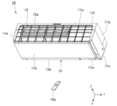
- FIG. 2 is a perspective view of the indoor unit according to the embodiment.
- FIG. 2 is a front view of the indoor unit according to the embodiment.
- FIG. 2 is a perspective view of a drain pan according to an embodiment.
- FIG. 2 is a side view of a control unit and a refrigerant sensor unit according to the embodiment.
- FIG. 2 is an exploded perspective view of a control unit and a refrigerant sensor unit according to the embodiment.
- FIG. 2 is a perspective view of the refrigerant sensor unit according to the embodiment.
- FIG. 2 is an exploded perspective view of the refrigerant sensor unit according to the embodiment.
- 2 is a perspective view of a housing main body of the refrigerant sensor unit according to the embodiment.
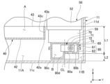
- FIG. FIG. 4 is a schematic diagram illustrating an area X in FIG. 3 .
- the drawings also show the X-axis, Y-axis, and Z-axis as appropriate.
- the X-axis shows one of the horizontal directions.
- the Y-axis shows the other of the horizontal directions.
- the Z-axis shows the vertical direction.
- the horizontal direction along the X-axis is called the "front-rear direction X”
- the horizontal direction along the Y-axis is called the "left-right direction Y”
- the vertical direction along the Z-axis is called the "vertical direction Z”.
- the front-rear direction X, the left-right direction Y, and the vertical direction Z are mutually perpendicular directions.
- the side in the vertical direction Z toward which the Z-axis arrow points (+Z side) is defined as the upper side
- the opposite side of the vertical direction Z toward which the Z-axis arrow points (-Z) is defined as the lower side.
- the left-right direction Y and the front-rear direction X are names simply used to describe the relative positional relationship of each part, and the actual positional relationship may be a positional relationship other than the positional relationship indicated by these names.
- the left-right direction Y corresponds to the "first direction”
- the right (+Y) corresponds to the "first side”
- the left corresponds to the "second side”.
- the front-rear direction X corresponds to the "second direction”
- the front (+X) corresponds to the "third side”
- the rear corresponds to the "fourth side”.
- Fig. 1 is a schematic diagram showing a general configuration of an air conditioner 100 in the present embodiment.
- the air conditioner 100 includes an indoor unit 10, an outdoor unit 20, and a refrigerant circuit 30.
- the indoor unit 10 is disposed indoors.
- the outdoor unit 20 is disposed outdoors.
- the indoor unit 10 and the outdoor unit 20 are connected to each other by the refrigerant circuit 30 through which refrigerant 33 circulates.
- the indoor unit 10 and the outdoor unit 20 are heat exchange units that exchange heat with air.
- the air conditioner 100 can adjust the temperature of the air in the room by exchanging heat between the refrigerant 33 flowing in the refrigerant circuit 30 and the air in the room in which the indoor unit 10 is located.
- the refrigerant 33 include fluorine-based refrigerants with low Global Warming Potential (GWP) or hydrocarbon-based refrigerants.
- GWP Global Warming Potential
- the refrigerant 33 include a single refrigerant selected from R1234yf, R1234ze, R32, and R290, or a mixture of two or more of these, or a mixture of any of these with another refrigerant.
- Examples of the refrigerant 33 include a mixed refrigerant containing R1132(E), or a mixed refrigerant containing R1123.
- refrigerant 33 examples include mixed refrigerants of R516A, R445A, R444A, R454C, R444B, R454A, R455A, R457A, R459B, R452B, R454B, R447B, R447A, R446A, and R459A.
- the outdoor unit 20 has a compressor 21, an outdoor heat exchanger 23, a flow control valve 24, an outdoor unit blower 25, and a four-way valve 22.
- the compressor 21, the outdoor heat exchanger 23, the flow control valve 24, and the four-way valve 22 are connected by a refrigerant circuit 30.
- the four-way valve 22 is disposed in a portion of the refrigerant circuit 30 that is connected to the discharge side of the compressor 21.
- the four-way valve 22 can reverse the direction of the refrigerant 33 flowing through the refrigerant circuit 30 by switching a portion of the path of the refrigerant circuit 30.
- the path connected by the four-way valve 22 is the path shown by the solid line on the four-way valve 22 in FIG. 1
- the refrigerant 33 flows through the refrigerant circuit 30 in the direction shown by the solid arrow in FIG. 1.
- the path connected by the four-way valve 22 is the path shown by the dashed line on the four-way valve 22 in FIG. 1
- the refrigerant 33 flows through the refrigerant circuit 30 in the direction shown by the dashed arrow in FIG. 1.
- the indoor unit 10 has a blower 15 and a heat exchanger 14 arranged around the blower 15.
- the indoor unit 10 is capable of cooling operation to cool the air in the room in which the indoor unit 10 is located, and heating operation to warm the air in the room in which the indoor unit 10 is located.
- the refrigerant 33 flowing through the refrigerant circuit 30 flows in the direction shown by the solid arrow in Figure 1.
- the refrigerant 33 flowing through the refrigerant circuit 30 circulates through the compressor 21, the outdoor heat exchanger 23 of the outdoor unit 20, the flow control valve 24, and the heat exchanger 14 of the indoor unit 10, in that order, before returning to the compressor 21.
- the outdoor heat exchanger 23 in the outdoor unit 20 functions as a condenser
- the heat exchanger 14 in the indoor unit 10 functions as an evaporator.
- the refrigerant 33 flowing in the refrigerant circuit 30 flows in the direction shown by the dashed line in Figure 1.
- the refrigerant 33 flowing in the refrigerant circuit 30 circulates through the compressor 21, the heat exchanger 14 of the indoor unit 10, the flow control valve 24, and the outdoor heat exchanger 23 of the outdoor unit 20, in that order, before returning to the compressor 21.
- the outdoor heat exchanger 23 in the outdoor unit 20 functions as an evaporator
- the heat exchanger 14 in the indoor unit 10 functions as a condenser.
- FIG. 2 is a perspective view of the indoor unit 10 of this embodiment.
- the indoor unit 10 of this embodiment is a wall-mounted indoor unit that is fixed to an upper region of a wall surface inside a room.
- a remote controller 10a is attached to the indoor unit 10.
- the remote controller 10a transmits radio waves such as infrared rays toward the indoor unit 10 when operated by a resident in the room. This allows the resident to remotely control the indoor unit 10 by operating the remote controller 10a.
- FIG. 3 is a front view of the indoor unit 10 with the front panel 11b removed.
- the indoor unit 10 of this embodiment includes a drain pan 40, a control unit 50, and a refrigerant sensor unit 60 in addition to the housing 11, heat exchanger 14, and blower 15 described above.
- the housing 11 houses the heat exchanger 14, the blower 15, the drain pan 40, the control unit 50, and the refrigerant sensor unit 60.
- the housing 11 of this embodiment is a substantially rectangular box shape that is long in the left-right direction Y.
- the housing 11 has a top panel 11a, a front panel 11b, a bottom panel 11c, a first side panel (side panel) 11d, a second side panel 11e, and a back panel 11f.
- the top panel 11a covers the internal space of the housing 11 from above.
- the front panel 11b covers the internal space of the housing 11 from the front (+X).
- the bottom panel 11c covers the internal space of the housing 11 from below.
- the first side panel 11d covers the internal space of the housing 11 from the right (+Y).
- the second side panel 11e covers the internal space of the housing 11 from the left (-Y).
- the back panel 11f covers the internal space of the housing 11 from the rear (-X).
- the housing 11 is provided with an intake port 12 and an exhaust port 13.
- the intake port 12 is provided on the top panel 11a.
- the intake port 12 opens upward and extends in the left-right direction Y.
- a filter 12a that removes dust from the intake air is disposed in the intake port 12.
- the exhaust port 13 is provided at the lower end of the front panel 11b.
- the exhaust port 13 opens forward (+X) and downward, and extends in the left-right direction Y.
- the exhaust port 13 is provided with an air direction vane 13a that adjusts the direction of the air blown out.
- a fan chamber 11A and a machine chamber 11B are provided in the internal space of the housing 11.
- the fan chamber 11A and the machine chamber 11B are arranged side by side in the left-right direction Y.
- the fan chamber 11A is equipped with a heat exchanger 14, a blower 15, and a drain pan 40.
- the fan chamber 11A is also connected to the intake port 12 and the exhaust port 13.
- the machine chamber 11B is arranged to the right (+Y) of the fan chamber 11A.
- the control unit 50 and the refrigerant sensor unit 60 are arranged in the machine chamber 11B.
- the blower 15 of this embodiment is a cross-flow fan.
- the blower 15 has an impeller 15a extending in the left-right direction Y and a drive motor 15b disposed to the right (+Y) of the impeller 15a.
- the impeller 15a is substantially cylindrical and has a plurality of blades (not shown) arranged in the circumferential direction.
- the impeller 15a and the drive motor 15b rotate the impeller 15a around a rotation axis extending in the left-right direction Y.
- the heat exchanger 14 is located in front (+X) and above (+Z) the blower 15.
- a refrigerant flows inside the heat exchanger 14.
- the heat exchanger 14 exchanges heat between the air in the fan chamber 11A and the refrigerant. In this way, the heat exchanger 14 cools or heats the air sucked into the blower 15.
- the drain pan 40 is disposed below the heat exchanger 14 and above the bottom panel 11c of the housing 11.
- the drain pan 40 extends in the left-right direction Y.
- the drain pan 40 receives condensed water that condenses and drips from the surface of the heat exchanger 14 from below.
- the condensed water received by the drain pan 40 is discharged to the outside via a drain hose (not shown).
- the drain pan 40 receives vaporized refrigerant (hereinafter referred to as refrigerant gas) from below in the event of refrigerant leakage from the heat exchanger 14.
- refrigerant gas vaporized refrigerant
- FIG 4 is an oblique view of the drain pan 40.
- the drain pan 40 has a drain pan main body 41 and a stabilizer portion 45.
- the drain pan 40 of this embodiment is a resin molded product in which the drain pan main body 41 and the stabilizer portion 45 are integrated.
- the drain pan main body 41 and the stabilizer portion 45 may be composed of separate members.
- the drain pan 40 receives condensation water and refrigerant gas in the drain pan main body 41, and regulates the air flow in the fan chamber 11A in the stabilizer portion 45.
- the drain pan main body 41 and the stabilizer portion 45 both extend in the left-right direction Y.
- the stabilizer portion 45 is positioned rearward (-X) of the drain pan main body 41.
- the stabilizer portion 45 has a tongue portion 46 that protrudes rearward (-X).
- the tongue portion 46 extends in the left-right direction Y.
- the tongue portion 46 faces the outer peripheral surface of the impeller 15a (see Figure 3) via a gap.
- the drain pan main body 41 has a storage space A that opens upward.
- the drain pan main body 41 is capable of storing condensed water in the storage space A.
- the drain pan main body 41 has a bottom 42 and a peripheral wall 43.
- the bottom 42 is plate-shaped and extends along a plane perpendicular to the vertical direction Z.
- the bottom 42 extends in the left-right direction Y.
- the bottom 42 faces the heat exchanger 14 in the vertical direction Z.
- the bottom 42 is located below the storage space A. Condensed water in the storage space A accumulates above the upper surface of the bottom 42.
- a drain hole (not shown) that connects to a drain hose is opened in the bottom 42.
- the peripheral wall portion 43 extends upward from the outer edge of the bottom portion 42. When viewed from above, the peripheral wall portion 43 surrounds the storage space A from the front, rear, left and right.
- the peripheral wall portion 43 has a front wall portion 43a, a rear wall portion 43b, a first side wall portion (side wall portion) 43c and a second side wall portion 43d.
- the front wall portion 43a is located in front of the storage space A (+X).
- the rear wall portion 43b is located in the rear of the storage space A (-X).
- the first side wall portion 43c is located to the right of the storage space A (+Y).
- the second side wall portion 43d is located to the left of the storage space A (-Y).
- the heights of the upper ends of each portion of the peripheral wall portion 43 are approximately the same. That is, the heights of the upper ends of the front wall portion 43a, the rear wall portion 43b, the first side wall portion 43c and the second side wall portion 43d are the same. However, the heights of the upper ends of the front wall portion 43a, the rear wall portion 43b, the first side wall portion 43c, and the second side wall portion 43d may be different from each other. In this case, it is preferable that the upper end of the first side wall portion 43c is located lower than the upper ends of the front wall portion 43a, the rear wall portion 43b, and the second side wall portion 43d.
- the front wall portion 43a and the rear wall portion 43b face each other in the front-to-rear direction X.
- the front wall portion 43a slopes in the forward (+X) direction as it extends upward.
- the rear wall portion 43b slopes in the backward (-X) direction as it extends upward.
- the front wall portion 43a and the rear wall portion 43b move away from each other in the front-to-rear direction X as they extend upward.
- the front wall portion 43a and the rear wall portion 43b ensure a wide opening of the storage space A in the front-to-rear direction X, and can receive condensation water over a wide range in the front-to-rear direction X and direct the condensation water to the upper surface of the bottom portion 42.
- the first side wall portion 43c and the second side wall portion 43d face each other in the left-right direction Y.
- the first side wall portion 43c and the second side wall portion 43d each extend along a plane perpendicular to the left-right direction Y.
- the first side wall portion 43c is located on the rightmost side (+Y) of the peripheral wall portion 43.
- the machine room 11B is provided between the first side wall portion 43c located on the rightmost side (+Y) of the peripheral wall portion 43 and the first side panel 11d of the housing 11.
- FIG. 5 is a side view of the control unit 50 and the refrigerant sensor unit 60.
- FIG. 6 is an exploded perspective view of the control unit 50 and the refrigerant sensor unit 60.
- the control unit 50 has an electrical equipment box 52, a control board 51, a terminal block 54, a cable 53, a cable guide 59, and a receiving device 58. That is, the indoor unit 10 has the electrical equipment box 52, the control board 51, the terminal block 54, the cable 53, the cable guide 59, and the receiving device 58.
- the control board 51 controls the components necessary for the cooling and heating operation of the air conditioner 100.
- the control board 51 controls each part of the indoor unit 10.
- the control board 51 controls the blower 15, the heat exchanger 14, etc.
- control board 51 can communicate with the control unit (not shown) of the outdoor unit 20 via the terminal block 54.
- a cable 53 extending from the outdoor unit 20 is connected to the terminal block 54.
- the terminal block 54 functions as a repeater for communication between the control board 51 of the indoor unit 10 and the control unit of the outdoor unit 20.
- the control board 51 has a number of electronic components mounted on its surface. These electronic components include, for example, transistors and a microcomputer. Note that in this embodiment, the control unit 50 has only one control board 51, but the control unit 50 may have a number of control boards 51. In this case, the multiple control boards 51 are connected to each other.
- the multiple cables 53 are connected to the control board 51 or the terminal block 54. Some of the multiple cables 53 connect each part of the indoor unit 10 to the control board 51. In addition, some of the multiple cables 53 connect the terminal block 54 to the control unit (not shown) of the outdoor unit 20.
- the electrical equipment box 52 is a box that houses the control board 51 or the terminal block 54 inside.
- An opening is provided in the lower part 52a of the electrical equipment box 52, which opens the internal space of the electrical equipment box 52 downward.
- a cable guide 59 that covers the opening is fixed to the lower part 52a of the electrical equipment box 52.
- the cable guide 59 has a hollow portion 59A inside that communicates with an opening provided in the lower portion 52a of the electrical equipment box.
- the cable guide 59 also has a cable insertion portion 59a that opens the hollow portion 59A rearward (-X).
- the multiple cables 53 are inserted from the cable insertion portion 59a and pass through the hollow portion 59A of the cable guide 59, and are guided from the lower portion 52a of the electrical equipment box 52 to the internal space of the electrical equipment box 52. In other words, the cable guide 59 guides the multiple cables 53 into the interior of the electrical equipment box 52.
- the cable guide 59 has a sensor fixing portion 59d and a receiver fixing portion 59b.
- the refrigerant sensor unit 60 is fixed to the sensor fixing portion 59d.
- the receiver 58 is fixed to the receiver fixing portion 59b.
- the sensor fixing portion 59d and the receiver fixing portion 59b are arranged side by side in the front-rear direction X.
- the sensor fixing portion 59d is located rearward (-X) of the receiver fixing portion 59b.
- the sensor fixing portion 59d has a sensor support surface 59f, a first boss 59e, and a locking portion 59g.
- the sensor support surface 59f is disposed between the first boss 59e and the locking portion 59g in the front-rear direction X.
- the sensor support surface 59f is a flat surface perpendicular to the vertical direction Z.
- the first boss 59e is located in front of the sensor support surface 59f (+X).
- the first boss 59e is cylindrical and protrudes downward.
- a screw hole 59h that opens downward is provided on the lower end surface of the first boss 59e.
- a fixing screw 59j that screws and fixes the refrigerant sensor unit 60 is inserted into the screw hole 59h.
- the receiving device 58 has an antenna unit (not shown), a receiving board (not shown) on which the antenna unit is mounted, a receiving device case 58a that houses them, and a display unit 58b provided on the front of the receiving device case 58a.
- the receiving device 58 receives radio waves from the remote controller 10a transmitted from the front (+X) of the indoor unit 10. For this reason, the receiving device 58 is arranged inside the housing 11 so as to face the front (+X). Furthermore, a window 11w is provided in the part of the front panel 11b of the housing 11 located in front (+X) of the receiving device 58 to prevent damage to the radio waves reaching the receiving device 58.
- the display unit 58b is, for example, a light-emitting diode, and displays the driving status of the indoor unit 10 by emitting light.
- the display unit 58b is arranged so as to be visible from the indoor side through the window 11w.
- the refrigerant sensor unit 60 is positioned to the right (+Y) of the drain pan 40.
- the refrigerant gas leaks from the heat exchanger 14
- the refrigerant gas is heavier than air and flows downward to accumulate in the storage space A of the drain pan 40.
- the refrigerant gas then flows over the first side wall portion 43c of the drain pan 40 into the machine chamber 11B, and accumulates above the bottom panel 11c, which is located below the drain pan 40.
- the refrigerant sensor unit 60 detects the refrigerant gas accumulating above the bottom panel 11c and transmits the detection result to the control unit 50.
- a component overlaps with another component in one direction means that the range of positions of the component in one direction overlaps with the range of positions of the other component in one direction. Therefore, “the refrigerant sensor unit 60 overlaps with the drain pan 40 in the front-to-rear direction X” means that the range of the refrigerant sensor unit 60 in the front-to-rear direction X from the front end to the rear end at least partially overlaps with the range of the drain pan 40 in the front-to-rear direction X from the front end to the rear end.
- FIG. 7 is a perspective view of the refrigerant sensor unit 60.
- FIG. 8 is an exploded perspective view of the refrigerant sensor unit 60.
- the refrigerant sensor unit 60 has a refrigerant sensor 70 and a housing 80.
- the refrigerant sensor 70 is housed inside the housing 80.
- the refrigerant sensor 70 has a sensor board 73, a sensor element 71, and an element case 72.
- the sensor board 73 is fixed to the inner surface of the housing 80.
- the sensor board 73 extends along a plane perpendicular to the front-rear direction X.
- the sensor board 73 has a mounting surface 73a on which multiple elements are mounted. In this embodiment, the mounting surface 73a faces forward (+X).
- the sensor element 71 detects vaporized refrigerant gas.
- the sensor element 71 is mounted on the mounting surface 73a of the sensor board 73.
- the sensor element 71 is surrounded by the element case 72.
- the element case 72 is cylindrical and extends forward (+X) from the mounting surface 73a.
- the element case 72 has a base end 72a fixed to the mounting surface 73a and a tip end 72b which is the end opposite the base end 72a.
- the base end 72a of the element case 72 is fixed to the mounting surface 73a without any gaps by adhesive or the like.
- the tip end 72b of the element case 72 is provided with a case opening 72h which introduces refrigerant gas into the inside of the element case 72.
- the refrigerant gas flows into the inside of the element case 72 from the case opening 72h.
- an accommodation space B is provided inside the housing 80 to accommodate the refrigerant sensor 70.
- a gas inlet 80a is provided on the bottom surface of the housing 80. The gas inlet 80a takes in the refrigerant gas leaking from the heat exchanger 14 into the accommodation space B.
- the housing 80 has a lid 81, a housing body 82, and a sealing member 89.
- the lid 81 and the housing body 82 are assembled together to define the storage space B.
- the direction in which the lid 81 and the housing body 82 are assembled is referred to as the assembly direction D1.
- the assembly direction D1 is the vertical direction Z.
- the housing body 82 is located below the lid 81.
- FIG 9 is a perspective view of the housing body 82.
- the housing body 82 has a second box-shaped portion 82b, a second flange portion 82c, a fixing plate portion 82e, a locking hook 84, and a pair of arms 82d.
- the second box-shaped portion 82b opens at a second opening 82a.
- the second opening 82a faces the lid body 81 side in the assembly direction D1.
- the second box-shaped portion 82b is provided with a gas inlet 80a.
- a groove 82m is provided on an inner surface 82k of the second box-shaped portion 82b that extends along a plane perpendicular to the front-rear direction X.
- the groove 82m is connected to the gas inlet 80a.
- the groove 82m extends upward (+Z) from the gas inlet 80a.
- the groove 82m faces the case opening 72h of the element case 72 shown in FIG. 8 in the front-rear direction X.
- the refrigerant gas that has entered the inside of the housing 80 from the gas inlet 80a is smoothly guided through the inside of the groove 82m to the case opening 72h.
- the refrigerant gas that has entered the inside of the housing 80 can be smoothly guided to the inside of the element case 72, and the refrigerant gas can be immediately detected by the sensor element 71 in the element case 72.
- the detection responsiveness of the refrigerant sensor unit 60 can be improved.
- the second box-shaped portion 82b is formed of a plurality of walls configured in a box shape.
- the plurality of walls of the second box-shaped portion 82b include a first wall portion 80b, a second wall portion 80d, a third wall portion 80e, and a lower end wall portion 80c.
- the first wall portion 80b and the lower end wall portion 80c extend along a plane perpendicular to the vertical direction Z.
- the lower end wall portion 80c is located at the lowest of the plurality of walls that constitute the second box-shaped portion 82b.
- the downward surface of the lower end wall portion 80c constitutes the lower end surface of the housing 80.
- the first wall portion 80b is located above the first wall portion 80b.
- a gas inlet 80a opens in the first wall portion 80b.
- the second wall portion 80d and the third wall portion 80e connect the first wall portion 80b and the lower end wall portion 80c.
- the second wall portion 80d extends downward from the left (-Y) end of the first wall portion 80b.
- the second wall portion 80d extends along a plane perpendicular to the left-right direction Y.
- the second wall portion 80d of this embodiment has a step portion, the second wall portion 80d may be a uniform flat plate.
- the second wall portion 80d of this embodiment overlaps the gas inlet 80a in the front-rear direction X.
- the range of the second wall portion 80d from the front end to the rear end in the front-rear direction X at least partially overlaps with the range of the gas inlet 80a from the front end to the rear end in the front-rear direction X.
- the third wall portion 80e extends downward from the rear (-X) end of the first wall portion 80b.
- the third wall portion 80e extends along a plane perpendicular to the front-rear direction X.
- the first opening 81a and the second opening 82a overlap each other. This connects the internal space of the first box-shaped portion 81b and the internal space of the second box-shaped portion 82b to form the storage space B.
- the second flange portion 82c is connected to the outer edge of the second opening 82a.
- the second flange portion 82c protrudes in a direction perpendicular to the assembly direction D1 and away from the second opening 82a.
- the second flange portion 82c surrounds the second opening 82a when viewed from the assembly direction D1.
- the pair of arms 82d are connected to the second flange portion 82c.
- the pair of arms 82d are arranged on both sides of the second opening 82a in the left-right direction Y.
- Each arm 82d has a pair of connecting pieces 82i extending toward the lid body 81 in the assembly direction D1, and a locking piece 82j connecting the tips of the pair of connecting pieces 82i.
- the tip surface of the protrusion 81d is inclined, when the housing body 82 is assembled to the lid body 81, the locking piece 82j slides along the tip surface of the protrusion 81d, and the pair of arms 82d are elastically deformed. This allows the operator to easily hook the locking piece 82j onto the protrusion 81d.
- the fixing plate portion 82e is a plate extending along a plane perpendicular to the vertical direction Z.
- the fixing plate portion 82e is provided on the outer edge of the second flange portion 82c.
- the fixing plate portion 82e protrudes in a direction perpendicular to the assembly direction D1 and away from the second opening 82a. In this embodiment, the fixing plate portion 82e protrudes forward (+X).
- the fixing plate portion 82e is provided with a screw insertion hole 82h that penetrates the fixing plate portion 82e in the thickness direction.
- the fixing screw 59j is inserted into the screw insertion hole 82h.
- the fixing screw 59j is also screwed into the screw hole 59h of the cable guide 59.
- the fixing plate portion 82e is fixed to the cable guide 59.
- the locking hook 84 is provided on the outer edge of the second flange portion 82c.
- the locking hook 84 protrudes in a direction perpendicular to the assembly direction D1 and away from the second opening 82a.
- the locking hook 84 protrudes rearward (-X).
- the locking hook 84 and the fixing plate portion 82e are located on opposite sides of the second opening 82a in the front-rear direction X, and protrude on opposite sides in the front-rear direction X.
- the locking hook 84 has a first protrusion 84a, a second protrusion 84b, and a locking plate portion 84c that are arranged in a crank shape.
- the first protrusion 84a extends rearward (-X) from the second flange portion 82c.
- the second protrusion 84b extends upward (+Z) from the tip of the first protrusion 84a.
- the locking plate portion 84c extends rearward (-X) from the upper end of the second protrusion 84b.
- the locking plate portion 84c is a plate-like member perpendicular to the assembly direction D1.
- the locking plate portion 84c is provided with a locking surface 84f facing downward.
- the locking surface 84f extends along a plane perpendicular to the vertical direction Z. As shown in FIG.
- the locking hook 84 is inserted into the notch 59k of the cable guide 59.
- the locking surface 84f of the locking hook 84 faces and contacts the upper surface of the locking portion 59g where the notch 59k is provided. As a result, the locking hook 84 is locked to the locking portion 59g.
- the sealing member 89 is sandwiched between the first flange portion 81c of the housing 80 and the second flange portion 82c of the housing main body 82.
- the sealing member 89 is composed of a sponge-like elastic member.
- the sealing member 89 is frame-shaped when viewed from the assembly direction D1.
- the sealing member 89 is compressed in the assembly direction D1 between the first flange portion 81c and the second flange portion 82c.
- the sealing member 89 closes the gap between the lid body 81 and the housing main body 82, sealing the storage space B from the outside.
- the procedure for fixing the refrigerant sensor unit 60 to the cable guide 59 will be described with reference to FIG. 6.
- the worker inserts the locking hook 84 of the refrigerant sensor unit 60 into the notch 59k of the cable guide 59 from the front (+X).
- the worker passes the fixing screw 59j through the screw insertion hole 82h of the refrigerant sensor unit 60, and further tightens the fixing screw 59j into the screw hole 59h of the cable guide 59.
- This causes the upper surface 60u of the refrigerant sensor unit 60 provided on the cover 81 to come into contact with and be pressed against the sensor support surface 59f of the cable guide 59.
- the refrigerant sensor unit 60 can be firmly fixed to the cable guide 59 by the process of tightening one fixing screw 59j.
- FIG. 10 is a schematic diagram of region X in FIG. 3, and is a diagram for explaining the arrangement of the drain pan 40, the control unit 50, and the refrigerant sensor unit 60.
- the refrigerant sensor unit 60 is arranged in the machine room 11B.
- the lower end wall portion 80c of the refrigerant sensor unit 60 is arranged along the bottom panel 11c of the housing 11. A small gap is provided between the lower surface of the lower end wall portion 80c and the upper surface of the bottom panel 11c.
- the first wall portion 80b located above the lower end wall portion 80c faces the bottom panel 11c in the vertical direction Z with a gap therebetween.
- the lower end wall portion 80c is provided with a gas inlet 80a that opens downward.
- the gas inlet 80a faces the bottom panel 11c.
- the refrigerant sensor unit 60 of this embodiment is disposed on the side of the drain pan 40, and can instantly detect refrigerant gas overflowing from the drain pan 40.
- the refrigerant sensor unit 60 by disposing the refrigerant sensor unit 60 near the drain pan 40, there is a concern that if condensed water that accumulates in the drain pan 40 flows out or splashes out of the drain pan 40, the condensed water may enter the inside of the refrigerant sensor unit 60.
- the gas inlet 80a of the housing 80 opens downward, so that condensed water is less likely to enter the gas inlet 80a. This makes it possible to prevent condensed water from affecting the operation of the refrigerant sensor 70, and improves the reliability of the refrigerant sensor unit 60.
- the distance dimension in the vertical direction Z between the gas inlet 80a and the upper end 43p of the first side wall portion 43c is referred to as the first vertical distance L1.
- the distance dimension in the vertical direction Z between the gas inlet 80a and the bottom panel 11c is referred to as the second vertical distance L2.
- the second vertical distance L2 is smaller than the first vertical distance L1 (L2 ⁇ L1).
- the refrigerant gas that accumulates above the bottom panel 11c can be easily caused to flow into the housing 80, improving the detection responsiveness of the refrigerant sensor unit 60. That is, according to this embodiment, by making the first vertical distance L1 relatively large and the second vertical distance L2 relatively small, the detection responsiveness of the refrigerant sensor unit 60 can be improved while ensuring the reliability of the refrigerant sensor unit 60.
- FIG. 10 also illustrates a center line CL located at the center of the housing 80 in the left-right direction Y.
- the gas inlet 80a is located on the opposite side of the drain pan 40 from the center line CL. Therefore, according to this embodiment, the gas inlet 80a is positioned to the right (+Y) of the center of the housing 80 in the left-right direction Y. According to this embodiment, the gas inlet 80a can be positioned sufficiently away from the drain pan 40 in the left-right direction Y, which can prevent condensed water from entering the housing 80.
- the indoor unit 10 of the present embodiment is an indoor unit 10 of an air conditioner 100.
- the indoor unit 10 includes a heat exchanger 14, a drain pan 40, a refrigerant sensor unit 60, and a housing 11.
- the heat exchanger 14 has a refrigerant flowing therethrough.
- the drain pan 40 is disposed below the heat exchanger 14.
- the refrigerant sensor unit 60 has a refrigerant sensor 70 capable of detecting vaporized refrigerant, and a housing 80 that accommodates the refrigerant sensor 70.
- the housing 11 accommodates the heat exchanger 14, the drain pan 40, and the refrigerant sensor unit 60. As shown in FIG.
- the drain pan 40 faces the heat exchanger 14 in the vertical direction Z, and has a bottom portion 42 extending in a left-right direction (first direction) Y intersecting the vertical direction Z, and a peripheral wall portion 43 extending upward from the outer edge of the bottom portion 42.
- the peripheral wall 43 includes a first side wall 43c extending upward from an end 42a on the right (first side, +Y) side of the bottom 42.
- the housing 11 has a bottom panel 11c located below the heat exchanger 14 and a first side panel 11d located to the right (+Y) of the heat exchanger 14.
- the refrigerant sensor unit 60 is disposed in the machine room 11B provided between the first side wall 43c and the first side panel 11d, and the position of the refrigerant sensor unit 60 in the front-rear direction (second direction) X perpendicular to both the vertical direction Z and the left-right direction Y overlaps with the drain pan 40.
- the housing 80 has a gas inlet 80a that opens downward.
- the vertical distance (second vertical distance L2) between the gas inlet 80a and the bottom panel 11c is smaller than the vertical distance (first vertical distance L1) between the gas inlet 80a and the upper end 43p of the first side wall 43c.
Landscapes
- Engineering & Computer Science (AREA)
- Chemical & Material Sciences (AREA)
- Combustion & Propulsion (AREA)
- Mechanical Engineering (AREA)
- General Engineering & Computer Science (AREA)
- Air Conditioning Control Device (AREA)
Abstract
本開示に係る室内機の一つの態様は、空気調和機の室内機であって、熱交換器と、熱交換器の下方に配置されるドレンパンと、ハウジングを有する冷媒センサユニットと、熱交換器、ドレンパン、および冷媒センサユニットを収容する筐体と、を備える。ドレンパンは、鉛直方向において熱交換器と対向し左右方向に延びる底部と、底部の外縁から上方に延びる周壁部と、を有する。周壁部は、底部の左右方向の第1側の端部から上方に延びる側壁部を含む。筐体は、熱交換器の下方に位置する底面パネルと、熱交換器に対し第1側に位置する側面パネルと、を有する。冷媒センサユニットは、側壁部と側面パネルとの間に設けられる機械室に配置され、前後方向の位置がドレンパンと重なる。ハウジングは、下向きに開口するガス流入口を有する。ガス流入口と底面パネルとの鉛直方向距離は、ガス流入口と側壁部の上端との鉛直方向距離よりも小さい。
Description
本開示は、室内機、および空気調和機に関する。
従来から、室内機に冷媒センサが取り付けられた空気調和機が知られている。特許文献1には、熱交換器の下方にドレンパンを配置し、さらに冷媒センサをドレンパンの近傍に配置することで、熱交換器から漏れ出してドレンパンを伝う冷媒ガスを冷媒センサで検出できる室内機が開示されている。
従来の室内機では、冷媒センサがドレンパンの近傍に配置されるため、ドレンパンに溜められた結露水が、不測の事態でドレンパンから流出、又は飛散した場合に結露水が冷媒センサにかかってしまい冷媒センサの検出精度に影響を与えるおそれがあった。
本開示は、上記のような事情に鑑みて、結露水が冷媒センサの検出精度に影響を与えることを抑制できる室内機、および空気調和機の提供を目的の一つとする。
本開示に係る室内機の一つの態様は、空気調和機の室内機であって、内部に冷媒が流れる熱交換器と、前記熱交換器の下方に配置されるドレンパンと、気化した前記冷媒を検出可能な冷媒センサ、および前記冷媒センサを収容するハウジングを有する冷媒センサユニットと、前記熱交換器、前記ドレンパン、および前記冷媒センサユニットを収容する筐体と、を備える。前記ドレンパンは、鉛直方向において前記熱交換器と対向し、鉛直方向と交差する第1方向に延びる底部と、前記底部の外縁から上方に延びる周壁部と、を有する。前記周壁部は、前記底部の前記第1方向の第1側の端部から上方に延びる側壁部を含む。前記筐体は、前記熱交換器の下方に位置する底面パネルと、前記熱交換器に対し前記第1側に位置する側面パネルと、を有する。前記冷媒センサユニットは、前記側壁部と前記側面パネルとの間に設けられる機械室に配置され、鉛直方向および前記第1方向の両方と直交する第2方向の位置が前記ドレンパンと重なる。前記ハウジングは、下向きに開口するガス流入口を有する。前記ガス流入口と前記底面パネルとの鉛直方向距離は、前記ガス流入口と前記側壁部の上端との鉛直方向距離よりも小さい。
本開示に係る空気調和機の一つの態様は、上記の室内機と、前記冷媒回路と、室外機と、を備える。
本開示によれば、結露水が冷媒センサの検出精度に影響を与えることを抑制できる室内機、および空気調和機を提供できる。
以下、図面を参照しながら、本開示の実施の形態について説明する。なお、本開示の範囲は、以下の実施の形態に限定されず、本開示の技術的思想の範囲内で任意に変更可能である。また、以下の図面においては、各構成をわかりやすくするために、各構造における縮尺および数などを、実際の構造における縮尺および数などと異ならせる場合がある。
また、図面には、適宜、X軸、Y軸、およびZ軸を示している。X軸は、水平方向のうちの一方向を示している。Y軸は、水平方向のうちの他の一方向を示している。Z軸は、鉛直方向を示している。以下の説明においては、X軸に沿った水平方向を“前後方向X”と呼び、Y軸に沿った水平方向を“左右方向Y”と呼び、Z軸に沿った鉛直方向を“鉛直方向Z”と呼ぶ。前後方向X、左右方向Y、および鉛直方向Zは、互いに直交する方向である。以下の説明においては、前後方向XのうちX軸の矢印が向く側(+X)を前方とし、前後方向XのうちX軸の矢印が向く側と逆側(-X)を後方とする。また、左右方向のうちY軸の矢印が向く側(+Y)を右方とし、左右方向YのうちY軸の矢印が向く側と逆側(-Y)を左方とする。さらに、鉛直方向ZのうちZ軸の矢印が向く側(+Z側)を上方とし、鉛直方向ZのうちZ軸の矢印が向く側と逆側(-Z)を下方とする。なお、左右方向Yおよび前後方向Xとは、単に各部の相対位置関係を説明するための名称であり、実際の配置関係等は、これらの名称で示される配置関係等以外の配置関係等であってもよい。また、以下の実施の形態において、左右方向Yは“第1方向”に相当し、右方(+Y)は“第1側”に相当し、左方は“第2側”に相当する。さらに、以下の実施の形態において、前後方向Xは“第2方向”に相当し、前方(+X)は“第3側”に相当し、後方は“第4側”に相当する。
<空気調和機>
図1は、本実施の形態における空気調和機100の概略構成を示す模式図である。図1に示すように、空気調和機100は、室内機10と、室外機20と、冷媒回路30と、を備える。室内機10は、室内に配置されている。室外機20は、屋外に配置されている。室内機10と室外機20とは、冷媒33が循環する冷媒回路30によって互いに接続されている。室内機10および室外機20は、空気との間で熱交換を行う熱交換ユニットである。
図1は、本実施の形態における空気調和機100の概略構成を示す模式図である。図1に示すように、空気調和機100は、室内機10と、室外機20と、冷媒回路30と、を備える。室内機10は、室内に配置されている。室外機20は、屋外に配置されている。室内機10と室外機20とは、冷媒33が循環する冷媒回路30によって互いに接続されている。室内機10および室外機20は、空気との間で熱交換を行う熱交換ユニットである。
空気調和機100は、冷媒回路30内を流れる冷媒33と室内機10が配置された室内の空気との間で熱交換を行うことによって、室内の空気の温度を調整可能である。冷媒33としては、例えば、地球温暖化係数(GWP:Global Warming Potential)が低いフッ素系冷媒、または炭化水素系冷媒などが挙げられる。冷媒33としては、例えば、R1234yf、R1234ze、R32、R290のいずれかの単一冷媒、もしくはこれらのいずれか2種以上の混合冷媒、またはこれらのいずれかと他の冷媒との混合冷媒が挙げられる。また、冷媒33としては、例えば、R1132(E)を含む混合冷媒、もしくはR1123を含む混合冷媒が挙げられる。また、冷媒33としては、例えば、R516A、R445A、R444A、R454C、R444B、R454A、R455A、R457A、R459B、R452B、R454B、R447B、R447A、R446A、R459Aの混合冷媒が挙げられる。
室外機20は、圧縮機21と、室外熱交換器23と、流量調整弁24と、室外機送風機25と、四方弁22と、を有する。圧縮機21と室外熱交換器23と流量調整弁24と四方弁22とは、冷媒回路30によって接続されている。
四方弁22は、冷媒回路30のうち圧縮機21の吐出側に繋がる部分に配置されている。四方弁22は、冷媒回路30の一部の経路を切り替えることで、冷媒回路30内を流れる冷媒33の向きを反転させることができる。四方弁22によって繋がれる経路が図1の四方弁22に実線で示す経路である場合、冷媒33は、冷媒回路30内を図1に実線の矢印で示す向きに流れる。一方、四方弁22によって繋がれる経路が図1の四方弁22に破線で示す経路である場合、冷媒33は、冷媒回路30内を図1に破線の矢印で示す向きに流れる。
室内機10は、送風機15と、送風機15の周囲に配置される熱交換器14と、を有する。室内機10は、室内機10が配置された室内の空気を冷やす冷房運転と、室内機10が配置された室内の空気を暖める暖房運転とが可能である。
室内機10が冷房運転される場合、冷媒回路30内を流れる冷媒33は、図1に実線の矢印で示す向きに流れる。つまり、室内機10が冷房運転される場合、冷媒回路30内を流れる冷媒33は、圧縮機21、室外機20の室外熱交換器23、流量調整弁24、および室内機10の熱交換器14をこの順に通って圧縮機21に戻るように循環する。冷房運転において、室外機20内の室外熱交換器23は凝縮器として機能し、室内機10内の熱交換器14は蒸発器として機能する。
一方、室内機10が暖房運転される場合、冷媒回路30内を流れる冷媒33は、図1に破線で示す向きに流れる。つまり、室内機10が暖房運転される場合、冷媒回路30内を流れる冷媒33は、圧縮機21、室内機10の熱交換器14、流量調整弁24、および室外機20の室外熱交換器23をこの順に通って圧縮機21に戻るように循環する。暖房運転において、室外機20内の室外熱交換器23は蒸発器として機能し、室内機10内の熱交換器14は凝縮器として機能する。
<室内機>
次に、本実施の形態の室内機10について、さらに詳細に説明する。
図2は、本実施の形態の室内機10の斜視図である。図2に示すように、本実施の形態の室内機10は、室内の壁面の上部領域に固定される壁掛け型の室内機である。室内機10には、リモートコントローラー10aが付属する。リモートコントローラー10aは、室内の居住者の操作によって室内機10に向けて赤外線などの電波を発信する。これにより、居住者は、リモートコントローラー10aを操作することで室内機10を遠隔操作できる。
次に、本実施の形態の室内機10について、さらに詳細に説明する。
図2は、本実施の形態の室内機10の斜視図である。図2に示すように、本実施の形態の室内機10は、室内の壁面の上部領域に固定される壁掛け型の室内機である。室内機10には、リモートコントローラー10aが付属する。リモートコントローラー10aは、室内の居住者の操作によって室内機10に向けて赤外線などの電波を発信する。これにより、居住者は、リモートコントローラー10aを操作することで室内機10を遠隔操作できる。
図3は、前面パネル11bが取り外された状態の室内機10の正面図である。図3に示すように、本実施の形態の室内機10は、上述した筐体11、熱交換器14、および送風機15に加えて、ドレンパン40、制御部50、および冷媒センサユニット60を備える。筐体11は、熱交換器14、送風機15、ドレンパン40、制御部50、および冷媒センサユニット60を収容する。
<筐体>
図2に示すように、本実施の形態の筐体11は、左右方向Yに長い略直方体箱状である。筐体11は、天面パネル11aと前面パネル11bと底面パネル11cと第1側面パネル(側面パネル)11dと第2側面パネル11eと背面パネル11fとを有する。天面パネル11aは、筐体11の内部空間を上方から覆う。前面パネル11bは、筐体11の内部空間を前方(+X)から覆う。底面パネル11cは、筐体11の内部空間を下方から覆う。第1側面パネル11dは、筐体11の内部空間を右方(+Y)から覆う。第2側面パネル11eは、筐体11の内部空間を左方(-Y)から覆う。背面パネル11fは、筐体11の内部空間を後方(-X)から覆う。
図2に示すように、本実施の形態の筐体11は、左右方向Yに長い略直方体箱状である。筐体11は、天面パネル11aと前面パネル11bと底面パネル11cと第1側面パネル(側面パネル)11dと第2側面パネル11eと背面パネル11fとを有する。天面パネル11aは、筐体11の内部空間を上方から覆う。前面パネル11bは、筐体11の内部空間を前方(+X)から覆う。底面パネル11cは、筐体11の内部空間を下方から覆う。第1側面パネル11dは、筐体11の内部空間を右方(+Y)から覆う。第2側面パネル11eは、筐体11の内部空間を左方(-Y)から覆う。背面パネル11fは、筐体11の内部空間を後方(-X)から覆う。
筐体11には、吸込口12と吹出口13とが設けられる。吸込口12は、天面パネル11aに設けられる。吸込口12は、上方に開口し、左右方向Yに延びる。吸込口12には、吸い込まれる空気から埃を除去するフィルタ12aが配置される。吹出口13は、前面パネル11bの下端部に設けられる。吹出口13は、前方(+X)および下方に開口し、左右方向Yに延びる。吹出口13には、吹き出される空気の風向を調整する風向ベーン13aが設けられる。
図3に示すように、筐体11の内部空間には、ファン室11Aと機械室11Bとが設けられる。ファン室11Aと機械室11Bとは、左右方向Yに並んで配置される。ファン室11Aには、熱交換器14、送風機15、およびドレンパン40が配置される。また、ファン室11Aは、吸込口12および吹出口13とそれぞれ繋がっている。機械室11Bは、ファン室11Aの右方(+Y)に配置される。機械室11Bには、制御部50、および冷媒センサユニット60が配置される。
<送風機>
本実施の形態の送風機15は、クロスフローファンである。送風機15は、左右方向Yに延びる羽根車15aと、羽根車15aの右方(+Y)に配置される駆動モータ15bと、を有する。羽根車15aは、周方向に並ぶ複数の翼部(図示略)を有する略筒状である。羽根車15aは、駆動モータ15bは、羽根車15aを左右方向Yに延びる回転軸線周りに回転させる。
本実施の形態の送風機15は、クロスフローファンである。送風機15は、左右方向Yに延びる羽根車15aと、羽根車15aの右方(+Y)に配置される駆動モータ15bと、を有する。羽根車15aは、周方向に並ぶ複数の翼部(図示略)を有する略筒状である。羽根車15aは、駆動モータ15bは、羽根車15aを左右方向Yに延びる回転軸線周りに回転させる。
<熱交換器>
熱交換器14は、送風機15の前方(+X)および上方(+Z)に位置する。熱交換器14の内部には、冷媒が流れる。熱交換器14は、ファン室11A内の空気と冷媒との間で熱交換を行う。これにより、熱交換器14は、送風機15に吸い込まれる空気を冷却又は加熱する。
熱交換器14は、送風機15の前方(+X)および上方(+Z)に位置する。熱交換器14の内部には、冷媒が流れる。熱交換器14は、ファン室11A内の空気と冷媒との間で熱交換を行う。これにより、熱交換器14は、送風機15に吸い込まれる空気を冷却又は加熱する。
<ドレンパン>
ドレンパン40は、熱交換器14の下方、かつ筐体11の底面パネル11cの上方に配置されている。ドレンパン40は、左右方向Yに延びる。ドレンパン40は、熱交換器14の表面で凝縮して滴下する結露水を下方から受け止める。ドレンパン40によって受け止められた結露水は、図示しないドレンホースを介して、屋外へと排出される。また、ドレンパン40は、熱交換器14から冷媒の漏出が発生した場合に、気化した冷媒(以下、冷媒ガスと呼ぶ)を下方から受け止める。ドレンパン40に溜った冷媒ガスは、ドレンパン40から溢れ出て冷媒センサユニット60に検出される。
ドレンパン40は、熱交換器14の下方、かつ筐体11の底面パネル11cの上方に配置されている。ドレンパン40は、左右方向Yに延びる。ドレンパン40は、熱交換器14の表面で凝縮して滴下する結露水を下方から受け止める。ドレンパン40によって受け止められた結露水は、図示しないドレンホースを介して、屋外へと排出される。また、ドレンパン40は、熱交換器14から冷媒の漏出が発生した場合に、気化した冷媒(以下、冷媒ガスと呼ぶ)を下方から受け止める。ドレンパン40に溜った冷媒ガスは、ドレンパン40から溢れ出て冷媒センサユニット60に検出される。
図4は、ドレンパン40の斜視図である。ドレンパン40は、ドレンパン本体部41と、スタビライザ部45と、を有する。本実施の形態のドレンパン40は、ドレンパン本体部41とスタビライザ部45とが一体となった樹脂成型品である。しかしながら、ドレンパン本体部41とスタビライザ部45とは、別部材から構成されていてもよい。ドレンパン40は、ドレンパン本体部41において、結露水、および冷媒ガスを受け止め、スタビライザ部45においてファン室11A内の空気の流れを整える。ドレンパン本体部41およびスタビライザ部45は、ともに左右方向Yに延びる。スタビライザ部45は、ドレンパン本体部41の後方(-X)に配置される。スタビライザ部45は、後方(-X)に突出する舌部46を有する。舌部46は、左右方向Yに延びる。舌部46は、羽根車15a(図3参照)の外周面に対し隙間を介して対向する。
ドレンパン本体部41は、上方に開口する貯留空間Aを有する。ドレンパン本体部41は、貯留空間Aにおいて結露水を貯留可能である。ドレンパン本体部41は、底部42と周壁部43とを有する。底部42は、鉛直方向Zと直交する平面に沿って延びる板状である。底部42は、左右方向Yに延びる。底部42は、鉛直方向Zにおいて熱交換器14と対向する。底部42は、貯留空間Aの下方に位置する。貯留空間A内の結露水は、底部42の上面の上方に溜る。底部42には、ドレンホースに繋がる排水孔(図示略)が開口する。
周壁部43は、底部42の外縁から上方に延びる。周壁部43は、上方から見て貯留空間Aを前後左右から囲む。周壁部43には、前壁部43aと後壁部43bと第1側壁部(側壁部)43cと第2側壁部43dとを有する。前壁部43aは、貯留空間Aの前方(+X)に位置する。後壁部43bは、貯留空間Aの後方(-X)に位置する。第1側壁部43cは、貯留空間Aの右方(+Y)に位置する。第2側壁部43dは、貯留空間Aの左方(-Y)に位置する。本実施の形態において、周壁部43の各部の上端の高さは略一致する。すなわち、前壁部43a、後壁部43b、第1側壁部43cおよび第2側壁部43dの上端の高さは、互いに一致する。しかしながら、前壁部43a、後壁部43b、第1側壁部43cおよび第2側壁部43dの上端の高さは、互いに異なっていてもよい。この場合、第1側壁部43cの上端が、前壁部43a、後壁部43b、および第2側壁部43dの上端よりも下方に位置することが好ましい。これにより、ドレンパン40の貯留空間Aに溜った冷媒ガスを第1側壁部43cから優先的に溢れさせることができる。結果的に、第1側壁部43cの右方(+Y)に設けられる機械室11Bに、ドレンパン40内の冷媒ガスを導きやすくすることができ、機械室11Bに配置される冷媒センサユニット60において冷媒ガスを即座に検出できる。
前壁部43aと後壁部43bとは、前後方向Xにおいて互いに対向する。前壁部43aは、上方に向かうに従い前方(+X)に位置する方向に傾斜する。後壁部43bは、上方に向かうに従い後方(-X)に位置する方向に傾斜する。すなわち、前壁部43aと後壁部43bとは、上方に向かうに従い前後方向Xにおいて互いに離間する。これにより、前壁部43aおよび後壁部43bは、貯留空間Aの開口を前後方向Xに広く確保し、前後方向Xの幅広い範囲の結露水を受け止めて底部42の上面に結露水を導くことができる。
第1側壁部43cと第2側壁部43dとは、左右方向Yにおいて互いに対向する。第1側壁部43cおよび第2側壁部43dは、それぞれ左右方向Yと直交する平面に沿って延びる。第1側壁部43cは、周壁部43において最も右方(+Y)に位置する。図3に示すように、機械室11Bは、周壁部43のうち右方(+Y)に位置する第1側壁部43cと筐体11の第1側面パネル11dとの間に設けられる。
<制御部>
図5は、制御部50、および冷媒センサユニット60の側面図である。図6は、制御部50、および冷媒センサユニット60の分解斜視図である。図6に示すように、制御部50は、電装品箱52と、制御基板51と、端子台54と、ケーブル53と、ケーブルガイド59と、受信装置58と、を有する。すなわち、室内機10は、電装品箱52、制御基板51、端子台54、ケーブル53、ケーブルガイド59、および受信装置58を備える。制御基板51は、空気調和機100の冷暖房運転に必要な構成部品の制御を行う。制御基板51は、室内機10の各部の制御を行う。制御基板51は、冷媒センサユニット60、および熱交換器14に設けられる各種センサの測定結果を基に、送風機15および熱交換器14などを制御する。また、制御基板51は、端子台54を介して、室外機20の制御部(図示略)と通信可能である。端子台54には、室外機20から延びるケーブル53が接続される。端子台54は、室内機10の制御基板51と室外機20の制御部との通信の中継器の機能を有する。
図5は、制御部50、および冷媒センサユニット60の側面図である。図6は、制御部50、および冷媒センサユニット60の分解斜視図である。図6に示すように、制御部50は、電装品箱52と、制御基板51と、端子台54と、ケーブル53と、ケーブルガイド59と、受信装置58と、を有する。すなわち、室内機10は、電装品箱52、制御基板51、端子台54、ケーブル53、ケーブルガイド59、および受信装置58を備える。制御基板51は、空気調和機100の冷暖房運転に必要な構成部品の制御を行う。制御基板51は、室内機10の各部の制御を行う。制御基板51は、冷媒センサユニット60、および熱交換器14に設けられる各種センサの測定結果を基に、送風機15および熱交換器14などを制御する。また、制御基板51は、端子台54を介して、室外機20の制御部(図示略)と通信可能である。端子台54には、室外機20から延びるケーブル53が接続される。端子台54は、室内機10の制御基板51と室外機20の制御部との通信の中継器の機能を有する。
制御基板51は、板面上に実装される複数の電子部品を有する。これら複数の電子部品は、例えば、トランジスタ、およびマイクロコンピュータを含む。なお、本実施の形態では、制御部50が1枚の制御基板51のみを有する場合について説明するが、制御部50は、複数枚の制御基板51を有していてもよい。この場合、複数の制御基板51同士は、互いに接続される。
複数のケーブル53は、制御基板51もしくは端子台54に接続される。複数のケーブル53の一部は、室内機10の各部と制御基板51とを繋ぐ。また、複数のケーブル53の一部は、端子台54と室外機20の制御部(図示略)とを繋ぐ。
電装品箱52は、制御基板51もしくは端子台54を内部に収容する箱である。電装品箱52の下部52aには、電装品箱52の内部空間を下方に開口させる開口部が設けられる。また、電装品箱52の下部52aには、開口部を覆うケーブルガイド59が固定される。
ケーブルガイド59の内部には、電装品箱の下部52aに設けられる開口部と連通する中空部59Aが設けられる。また、ケーブルガイド59は、中空部59Aを後方(-X)に開口させるケーブル挿入部59aを有する。複数のケーブル53は、ケーブル挿入部59aから挿入されてケーブルガイド59の中空部59Aを通り、電装品箱52の下部52aから電装品箱52の内部空間に導かれる。すなわち、ケーブルガイド59は、複数のケーブル53を電装品箱52の内部に導く。
ケーブルガイド59は、センサ固定部59dと受信装置固定部59bとを有する。センサ固定部59dには、冷媒センサユニット60が固定される。受信装置固定部59bには、受信装置58が固定される。センサ固定部59dと受信装置固定部59bとは前後方向Xに並んで配置される。また、センサ固定部59dは、受信装置固定部59bの後方(-X)に位置する。
センサ固定部59dは、センサ支持面59fと、第1ボス59eと、係止部59gと、を有する。センサ支持面59fは、前後方向Xにおいて、第1ボス59eと係止部59gとの間に配置される。センサ支持面59fは、鉛直方向Zと直交する平坦面である。第1ボス59eは、センサ支持面59fの前方(+X)に位置する。第1ボス59eは、下方に突出する円柱状である。第1ボス59eの下端面には、下方に開口するネジ孔59hが設けられる。ネジ孔59hには、冷媒センサユニット60をねじ固定する固定ネジ59jが挿入される。係止部59gは、鉛直方向Zと直交する平面に沿って延びる板状である。係止部59gは、センサ支持面59fの後方(-X)に位置する。また、係止部59gは、センサ支持面59fよりも下方に位置する。係止部59gは、前方(+X)を向く前端縁を有する。係止部59gの前端縁には、切欠部59kが設けられる。切欠部59kは、前方(+X)に開口する。センサ固定部59dにおける冷媒センサユニット60の固定方法については、後段において説明する。
受信装置固定部59bは、左右方向Yに並ぶ複数の第2ボス59cを有する。第2ボス59cは、下方に突出する円柱状である。第2ボス59cの下端面には、下方に開口するネジ孔が設けられる。受信装置58は、第2ボス59cに下方からネジ止めされる。すなわち、受信装置58は、ケーブルガイド59に固定される。
受信装置58は、アンテナ部(図示略)と、当該アンテナ部が実装される受信基板(図示略)と、これらを収容する受信装置ケース58aと、受信装置ケース58aの前面に設けられる表示部58bと、を有する。受信装置58は、室内機10の前方(+X)から送信されるリモートコントローラー10aの電波を受信する。このため、受信装置58は、筐体11の内部で前方(+X)を向くように配置される。さらに、筐体11の前面パネル11bにおいて受信装置58の前方(+X)に位置する部分には、受信装置58に到達する電波を損害しないための窓部11wが設けられる。表示部58bは、例えば発光ダイオードであり、発光によって室内機10の駆動状態などを表示する。表示部58bは、窓部11w介して室内側から視認可能に配置される。
<冷媒センサユニット>
冷媒センサユニット60は、制御部50の下方に配置される。冷媒センサユニット60は、ケーブルガイド59に着脱可能に固定される。図5に示すように、本実施の形態の冷媒センサユニット60は、受信装置58に対し後方(-X)に位置する。また、図6に示すように、冷媒センサユニット60は、前後方向Xから見て少なくとも一部が受信装置58に重なる。本実施の形態によれば、冷媒センサユニット60と受信装置58とを前後方向Xに並べて配置し、機械室11Bの左右方向Yに小型化することができる。また、冷媒センサユニット60を受信装置58の後方(-X)に配置することで、冷媒センサユニット60が、リモートコントローラー10aから受信装置58に到達する電波を阻害することを抑制できる。
冷媒センサユニット60は、制御部50の下方に配置される。冷媒センサユニット60は、ケーブルガイド59に着脱可能に固定される。図5に示すように、本実施の形態の冷媒センサユニット60は、受信装置58に対し後方(-X)に位置する。また、図6に示すように、冷媒センサユニット60は、前後方向Xから見て少なくとも一部が受信装置58に重なる。本実施の形態によれば、冷媒センサユニット60と受信装置58とを前後方向Xに並べて配置し、機械室11Bの左右方向Yに小型化することができる。また、冷媒センサユニット60を受信装置58の後方(-X)に配置することで、冷媒センサユニット60が、リモートコントローラー10aから受信装置58に到達する電波を阻害することを抑制できる。
図3に示すように、冷媒センサユニット60は、ドレンパン40の右方(+Y)に配置される。熱交換器14から冷媒ガスが漏れ出した場合、冷媒ガスは、空気よりも重いため下方に流れてドレンパン40の貯留空間Aに溜まる。さらに、冷媒ガスは、ドレンパン40の第1側壁部43cを越えて、機械室11B内に流入し、ドレンパン40よりも下方に位置する底面パネル11cの上方に溜っていく。冷媒センサユニット60は、底面パネル11cの上方に溜っていく冷媒ガスを検出し、検出結果を制御部50に送信する。
図4に、ドレンパン40に対する冷媒センサユニット60の配置を模式的に示す。図4に示すように、冷媒センサユニット60は、ドレンパン40の第1側壁部43cの右方(+Y)に配置される。また、冷媒センサユニット60は、前後方向Xの位置がドレンパン40と重なる。本実施の形態によれば、冷媒センサユニット60は、ドレンパン40の右方(+Y)であって近傍に配置されることで、ドレンパン40から右方(+Y)に溢れ出た冷媒ガスを即座に検出し易い。
なお、本明細書において、「一の部材は、一の方向の位置が他の部材と重なる」とは、一の部材の一の方向における位置の範囲が、他の部材の一の方向における位置の範囲と、重なっていることを意味している。したがって、「冷媒センサユニット60は、前後方向Xの位置がドレンパン40と重なる」とは、冷媒センサユニット60の前端から後端までの前後方向Xの範囲が、ドレンパン40の前端から後端までの前後方向Xの範囲と少なくとも一部において重なることを意味している。
図7は、冷媒センサユニット60の斜視図である。図8は、冷媒センサユニット60の分解斜視図である。図8に示すように、冷媒センサユニット60は、冷媒センサ70とハウジング80とを有する。冷媒センサ70は、ハウジング80の内部に収容される。冷媒センサ70は、センサ基板73とセンサ素子71と素子ケース72とを有する。
センサ基板73は、ハウジング80の内側面に固定される。センサ基板73は、前後方向Xと直交する平面に沿って延びる。センサ基板73は、複数の素子が実装される実装面73aを有する。本実施の形態の実装面73aは、前方(+X)を向く面である。
センサ素子71は、気化した冷媒ガスを検出する。センサ素子71は、センサ基板73の実装面73aに実装される。センサ素子71は、素子ケース72に囲まれる。これにより、センサ素子71は、素子ケース72によって保護される。素子ケース72は、実装面73aから前方(+X)に延びる円筒状である。素子ケース72は、実装面73aに固定される基端部72aと、基端部72aの反対側の端部である先端部72bと、を有する。素子ケース72の基端部72aは、接着剤などによって、実装面73aに対し隙間なく固定される。素子ケース72の先端部72bには、素子ケース72の内部に冷媒ガスを導くケース開口部72hが設けられる。冷媒ガスは、ケース開口部72hから素子ケース72の内部に流入する。
図7に示すように、ハウジング80の内部には、冷媒センサ70を収容する収容空間Bが設けられる。また、ハウジング80の下面には、ガス流入口80aが設けられる。ガス流入口80aは、熱交換器14から漏れ出した冷媒ガスを収容空間Bに取り込む。
図8に示すように、ハウジング80は、蓋体81と、ハウジング本体82と、封止部材89と、を有する。蓋体81とハウジング本体82とは、互いに組み付けられて収容空間Bを構成する。本明細書において、蓋体81とハウジング本体82とが組み付けられる方向を組付方向D1と呼ぶ。本実施の形態において、組付方向D1は、鉛直方向Zである。また、本実施の形態において、ハウジング本体82は、蓋体81に対し下方に位置する。
蓋体81は、第1箱状部81bと、第1フランジ部81cと、一対の突起81dと、を有する。第1箱状部81bは、第1開口81aにおいて下方に開口する。第1開口81aは、組付方向D1のハウジング本体82側を向く。第1フランジ部81cは、第1開口81aの外縁に繋がる。第1フランジ部81cは、組付方向D1と直交する方向であり第1開口81aから離れる方向に突出する。第1フランジ部81cは、組付方向D1から見て第1開口81aを囲む。一対の突起81dは、第1フランジ部81cの側面に設けられる。一対の突起81dは、第1開口81aを挟むように第1開口81aの左右方向Yの両側に配置される。一対の突起81dは、それぞれ組付方向D1と直交する方向でありそれぞれ第1開口81aから離れる方向に突出する。突起81dの先端面は、組付方向D1においてハウジング本体82から離れるに従い突出高さを高くする方向に傾斜する。
図9は、ハウジング本体82の斜視図である。図9に示すように、ハウジング本体82は、第2箱状部82bと、第2フランジ部82cと、固定用板部82eと、係止フック84と、一対の腕部82dと、を有する。第2箱状部82bは、第2開口82aにおいて開口する。第2開口82aは、組付方向D1の蓋体81側を向く。
第2箱状部82bには、ガス流入口80aが設けられる。また、第2箱状部82bの内側面のうち前後方向Xと直交する平面に沿って延びる内側面82kには凹溝部82mが設けられる。凹溝部82mは、ガス流入口80aに繋がっている。凹溝部82mは、ガス流入口80aから上方(+Z)に延びる。凹溝部82mは、図8に示す素子ケース72のケース開口部72hと前後方向Xにおいて対向する。第2箱状部82bの内側面82kに凹溝部82mが設けられることで、ガス流入口80aからハウジング80の内部に侵入した冷媒ガスが、凹溝部82mの内部を通ってケース開口部72hまで円滑に導かられる。これにより、ハウジング80の内部に侵入した冷媒ガスを素子ケース72の内部に円滑に導き、素子ケース72内のセンサ素子71で冷媒ガスを即座に検出できる。結果的に冷媒センサユニット60の検出の応答性を高めることができる。
図8に示すように、第2箱状部82bは、箱状に構成される複数の壁部によって構成される。第2箱状部82bの複数の壁部は、第1壁部80b、第2壁部80d、第3壁部80e、および下端壁部80cを含む。第1壁部80bおよび下端壁部80cは、鉛直方向Zと直交する平面に沿って延びる。下端壁部80cは、第2箱状部82bを構成する複数の壁部のうち最も下方に位置する。下端壁部80cの下方を向く面は、ハウジング80の下端面を構成する。第1壁部80bは、第1壁部80bよりも上方に位置する。第1壁部80bには、ガス流入口80aが開口する。第2壁部80dおよび第3壁部80eは、第1壁部80bと下端壁部80cとを繋ぐ。第2壁部80dは、第1壁部80bの左方(-Y)の端部から下方に延びる。第2壁部80dは、左右方向Yと直交する平面に沿って延びる。本実施の形態の第2壁部80dには、段差部分が設けられているが、第2壁部80dは一様な平坦の平板状であってもよい。本実施の形態の第2壁部80dは、前後方向Xの位置がガス流入口80aと重なる。すなわち、第2壁部80dの前端から後端までの前後方向Xの範囲が、ガス流入口80aの前端から後端までの前後方向Xの範囲と少なくとも一部において重なる。第3壁部80eは、第1壁部80bの後方(-X)の端部から下方に延びる。第3壁部80eは、前後方向Xと直交する平面に沿って延びる。
ハウジング本体82を蓋体81に組み付けることで、第1開口81aと第2開口82aとは、互いに重なり合う。これにより、第1箱状部81bの内部空間と第2箱状部82bの内部空間とが繋がり収容空間Bを構成する。第2フランジ部82cは、第2開口82aの外縁に繋がる。第2フランジ部82cは、組付方向D1と直交する方向であり第2開口82aから離れる方向に突出する。第2フランジ部82cは、組付方向D1から見て第2開口82aを囲む。一対の腕部82dは、第2フランジ部82cに接続される。
一対の腕部82dは、第2開口82aの左右方向Yの両側に配置される。それぞれの腕部82dは、組付方向D1の蓋体81側に延びる一対の連結片82iと、一対の連結片82iの先端同士を繋ぐ係止片82jと、を有する。ハウジング本体82を蓋体81に組み付けることで、一対の連結片82iと係止片82jと第2フランジ部82cの外縁とで囲まれた部分には、蓋体81の突起81dが挿入される。一対の突起81dが、一対の係止片82jにそれぞれ引っ掛かることで、ハウジング本体82が蓋体81に固定される。また、突起81dの先端面が傾斜するため、ハウジング本体82を蓋体81に組み付ける際に、突起81dの先端面に沿って係止片82jが滑り一対の腕部82dが弾性変形する。これにより、作業者は係止片82jを、容易に突起81dに引っ掛けることができる。
固定用板部82eは、鉛直方向Zと直交する平面に沿って延びる板状である。固定用板部82eは、第2フランジ部82cの外縁に設けられる。固定用板部82eは、組付方向D1と直交する方向であり第2開口82aから離れる方向に突出する。本実施の形態の固定用板部82eは、前方(+X)に突出する。固定用板部82eには、固定用板部82eを厚さ方向に貫通するネジ挿通孔82hが設けられる。図6に示すように、ネジ挿通孔82hには、固定ネジ59jが挿入される。また、固定ネジ59jは、ケーブルガイド59のネジ孔59hに締め込まれる。これにより、固定用板部82eは、ケーブルガイド59に固定される。
図9に示すように、係止フック84は、第2フランジ部82cの外縁に設けられる。係止フック84は、組付方向D1と直交する方向であり第2開口82aから離れる方向に突出する。本実施の形態の係止フック84は、後方(-X)に突出する。係止フック84と固定用板部82eとは、第2開口82aに対し前後方向Xの互いに反対側に位置し、前後方向Xの反対側に突出する。係止フック84は、クランク状に配置される第1突出部84a、第2突出部84b、および係止板部84cを有する。第1突出部84aは、第2フランジ部82cから後方(-X)に延びる。第2突出部84bは、第1突出部84aの先端から上方(+Z)に延びる。係止板部84cは、第2突出部84bの上端から後方(-X)に延びる。係止板部84cは、組付方向D1と直交する板状である。係止板部84cには、下方を向く係止面84fが設けられる。係止面84fは、鉛直方向Zと直交する平面に沿って延びる。図6に示すように、冷媒センサユニット60をケーブルガイド59に固定した状態で、係止フック84は、ケーブルガイド59の切欠部59kに挿入される。また、係止フック84の係止面84fは、切欠部59kが設けられ係止部59gの上面に対向し接触する。これにより、係止フック84は、係止部59gに係止される。
図8に示すように、封止部材89は、ハウジング80の第1フランジ部81cとハウジング本体82の第2フランジ部82cとの間に挟み込まれる。封止部材89は、スポンジ状の弾性部材から構成される。封止部材89は、組付方向D1からみて枠状である。封止部材89は、第1フランジ部81cと第2フランジ部82cとの間で組付方向D1に圧縮される。これにより、封止部材89は、蓋体81とハウジング本体82との間の隙間を塞いで収容空間Bを外部に対し密閉する。
図6を基に、冷媒センサユニット60をケーブルガイド59に固定する手順について説明する。まず、作業者は、冷媒センサユニット60の係止フック84を、ケーブルガイド59の切欠部59kに前方(+X)から挿入する。次いで、作業者は、冷媒センサユニット60のネジ挿通孔82hに固定ネジ59jを通し、さらに固定ネジ59jをケーブルガイド59のネジ孔59hに締め込む。これにより、蓋体81に設けられる冷媒センサユニット60の上面60uが、ケーブルガイド59のセンサ支持面59fに接触し押し当てられる。本実施の形態によれば、1つの固定ネジ59jを締め込む工程によって、冷媒センサユニット60をケーブルガイド59に強固に固定することができる。
図10は、図3の領域Xを模式化した模式図であり、ドレンパン40、制御部50、冷媒センサユニット60の配置を説明するための図である。冷媒センサユニット60は、機械室11Bに配置される。冷媒センサユニット60の下端壁部80cは、筐体11の底面パネル11cに沿って配置される。下端壁部80cの下面と底面パネル11cの上面との間には、わずかな隙間が設けられる。また、下端壁部80cよりも上方に位置する第1壁部80bは、隙間を空けて底面パネル11cと鉛直方向Zに対向する。上述したように、下端壁部80cには、下向きに開口するガス流入口80aが設けられる。ガス流入口80aは、底面パネル11cと対向する。
本実施の形態の冷媒センサユニット60は、ドレンパン40の側部に配置されることでドレンパン40から溢れ出た冷媒ガスを即座に検出できる。しかしながら一方で、冷媒センサユニット60がドレンパン40の近傍に配置されることで、ドレンパン40に溜る結露水がドレンパン40から流出又は飛散した場合に、結露水が冷媒センサユニット60の内部に侵入してしまうことが懸念される。本実施の形態によれば、ハウジング80のガス流入口80aは、下向きに開口するため、ガス流入口80aに結露水が侵入しにくい。このため、結露水が冷媒センサ70の動作に影響を与えることを抑制でき、冷媒センサユニット60の信頼性を高めることができる。
本明細書において、ガス流入口80aと第1側壁部43cの上端43pとの鉛直方向Zにおける距離寸法を第1鉛直方向距離L1とする。また、ガス流入口80aと底面パネル11cとの鉛直方向Zにおける距離寸法を第2鉛直方向距離L2とする。本実施の形態において、第2鉛直方向距離L2は、第1鉛直方向距離L1よりも小さい(L2<L1)。ドレンパン40に溜る結露水がドレンパン40から流出、又は飛散する場合、結露水はドレンパン40の第1側壁部43cを超えて機械室11Bに侵入する。このため、第1鉛直方向距離L1を十分に大きく確保することでドレンパン40から流出、又は飛散する結露水が、ガス流入口80aに達し難くなる。また、第2鉛直方向距離L2を十分に小さくすることで、底面パネル11cの上方に溜る冷媒ガスをハウジング80内に流入させやすくなり、冷媒センサユニット60の検出の応答性を高めることができる。すなわち、本実施の形態によれば、第1鉛直方向距離L1を相対的に大きく、第2鉛直方向距離L2を相対的に小さくすることで、冷媒センサユニット60の信頼性を確保しつつ検出の応答性を高めることができる。
また、図10には、ハウジング80の左右方向Yの中央に位置する中央線CLを図示する。本実施の形態において、ガス流入口80aは、中央線CLに対しドレンパン40の反対側に位置する。したがって、本実施の形態によれば、ガス流入口80aは、ハウジング80の左右方向Yの中央よりも右方(+Y)に配置される。本実施の形態によれば、左右方向Yにおいてガス流入口80aをドレンパン40から十分に離間して配置することができ、ハウジング80内への結露水の侵入を抑制できる。
<まとめ>
図1に示すように、本実施の形態の室内機10は、空気調和機100の室内機10である。また、図3に示すように、室内機10は、熱交換器14と、ドレンパン40と、冷媒センサユニット60と、筐体11と、備える。熱交換器14は、内部に冷媒が流れる。ドレンパン40は、熱交換器14の下方に配置される。冷媒センサユニット60は、気化した冷媒を検出可能な冷媒センサ70、および冷媒センサ70を収容するハウジング80を有する。筐体11は、熱交換器14、ドレンパン40、および冷媒センサユニット60を収容する。図10に示すように、ドレンパン40は、鉛直方向Zにおいて熱交換器14と対向し、鉛直方向Zと交差する左右方向(第1方向)Yに延びる底部42と、底部42の外縁から上方に延びる周壁部43と、を有する。周壁部43は、底部42の右方(第1側、+Y)の端部42aから上方に延びる第1側壁部43cを含む。筐体11は、熱交換器14の下方に位置する底面パネル11cと、熱交換器14に対し右方(+Y)に位置する第1側面パネル11dと、を有する。冷媒センサユニット60は、第1側壁部43cと第1側面パネル11dとの間に設けられる機械室11Bに配置され、鉛直方向Zおよび左右方向Yの両方と直交する前後方向(第2方向)Xの位置がドレンパン40と重なる。ハウジング80は、下向きに開口するガス流入口80aを有する。ガス流入口80aと底面パネル11cとの鉛直方向距離(第2鉛直方向距離L2)は、ガス流入口80aと第1側壁部43cの上端43pとの鉛直方向距離(第1鉛直方向距離L1)よりも小さい。
図1に示すように、本実施の形態の室内機10は、空気調和機100の室内機10である。また、図3に示すように、室内機10は、熱交換器14と、ドレンパン40と、冷媒センサユニット60と、筐体11と、備える。熱交換器14は、内部に冷媒が流れる。ドレンパン40は、熱交換器14の下方に配置される。冷媒センサユニット60は、気化した冷媒を検出可能な冷媒センサ70、および冷媒センサ70を収容するハウジング80を有する。筐体11は、熱交換器14、ドレンパン40、および冷媒センサユニット60を収容する。図10に示すように、ドレンパン40は、鉛直方向Zにおいて熱交換器14と対向し、鉛直方向Zと交差する左右方向(第1方向)Yに延びる底部42と、底部42の外縁から上方に延びる周壁部43と、を有する。周壁部43は、底部42の右方(第1側、+Y)の端部42aから上方に延びる第1側壁部43cを含む。筐体11は、熱交換器14の下方に位置する底面パネル11cと、熱交換器14に対し右方(+Y)に位置する第1側面パネル11dと、を有する。冷媒センサユニット60は、第1側壁部43cと第1側面パネル11dとの間に設けられる機械室11Bに配置され、鉛直方向Zおよび左右方向Yの両方と直交する前後方向(第2方向)Xの位置がドレンパン40と重なる。ハウジング80は、下向きに開口するガス流入口80aを有する。ガス流入口80aと底面パネル11cとの鉛直方向距離(第2鉛直方向距離L2)は、ガス流入口80aと第1側壁部43cの上端43pとの鉛直方向距離(第1鉛直方向距離L1)よりも小さい。
上述の構成によれば、ドレンパン40を熱交換器14の下方に配置することで、熱交換器14から漏出した冷媒ガスをドレンパン40で受け止めることができる。また、冷媒センサユニット60が、ドレンパン40の第1側壁部43cの右方(+Y)で前後方向Xの位置がドレンパン40と重なるように配置されることで、第1側壁部43cを超えてドレンパン40から溢れ出た冷媒ガスを冷媒センサユニット60に即座に検出させることができる。しかしながら、冷媒センサユニット60が、熱交換器14の近傍に配置されることで、ドレンパン40によって受け止める結露水の一部がドレンパン40から流出又は飛散などした場合に、冷媒センサユニット60に達し易くなる。上述の構成によれば、ハウジング80のガス流入口80aが下向きに開口することでガス流入口80aを介して結露水がハウジング80の内部に侵入することを抑制できる。また、結露水がドレンパン40から流出、又は飛散する場合、結露水はドレンパン40の第1側壁部43cを超えて冷媒センサユニット60側に達する。上述の構成によれば、第1鉛直方向距離L1を十分に大きく確保することで、結露水がドレンパン40からガス流入口80aに達し難くなり、ハウジング80内への結露水の侵入を抑制できる。このため、結露水が冷媒センサ70の動作に影響を与えることを抑制でき、冷媒センサユニット60の信頼性を高めることができる。加えて、上述の構成によれば、第2鉛直方向距離L2を十分に小さくすることで、冷媒ガスが底面パネル11cの上方に溜った際に即座にハウジング80内に流入させることができ、冷媒ガスの漏れ出しに対する冷媒センサユニット60の検出の応答性を高めることができる。
本実施の形態の室内機10において、ガス流入口80aは、ハウジング80の左右方向Yの中央である中央線CLよりも右方(+Y)に配置される。この構成によれば、ガス流入口80aを中央線CLよりも左方(-Y)に配置される場合と比較して、左右方向Yにおいてガス流入口80aをドレンパン40から十分に離間して配置することができる。結果的に、ドレンパン40からガス流入口80aに結露水が達し難くなり、ハウジング80内への結露水の侵入を抑制でき、冷媒センサユニット60の信頼性を高めることができる。
本実施の形態の室内機10において、ハウジング80は、ガス流入口80aが開口する第1壁部80bと、第1壁部80bの左方(-Y)の端部から下方に延びる第2壁部80dと、を有する。また、図8に示すように、第2壁部80dは、前後方向Xの位置がガス流入口80aと重なる。この構成によれば、第2壁部80dが、ガス流入口80aとドレンパン40との間に配置される。このため、ドレンパン40から飛散した結露水の一部が、ハウジング80の外表面に付着する場合であっても、結露水は第2壁部80dを伝って下方に流れ、ガス流入口80aに達し難くなり、ガス流入口80aへの結露水の侵入を抑制できる。
本実施の形態の室内機10は、図6に示すように、機械室11Bに配置され、内部に制御基板51もしくは端子台54を収容する電装品箱52と、電装品箱52の下部に固定され、制御基板51もしくは端子台54に接続されるケーブル53を電装品箱52の内部に導くケーブルガイド59と、を備える。冷媒センサユニット60は、ケーブルガイド59に着脱可能に固定される。この構成によれば、ケーブルガイド59を利用して冷媒センサユニット60を電装品箱52に固定することができる。このため、冷媒センサユニット60を固定するための部品を別途用意する必要がなく、室内機10の部品点数を削減して、省資源化を図ることができる。さらに、冷媒センサユニット60がケーブルガイド59に対し着脱可能であることで、冷媒センサユニット60のメンテナンスが容易となる。
本実施の形態の室内機10は、ケーブルガイド59に固定され、前方(第3側、+X)から送信されるリモートコントローラー10aの電波を受信する受信装置58を備える。冷媒センサユニット60は、受信装置58に対し後方(第4側、-X)に位置し、前後方向Xから見て少なくとも一部が受信装置58に重なる。冷媒センサユニット60と受信装置58とを前後方向Xに並べて配置して受信装置58の後方(-X)の領域を有効利用することができ、冷媒センサユニット60に伴う機械室11Bの大型化を抑制できる。また、冷媒センサユニット60を受信装置58の後方(-X)に配置することで、冷媒センサユニット60が、リモートコントローラー10aから受信装置58に到達する電波を阻害することを抑制できる。
以上に本開示における実施の形態について説明したが、本開示は上述した各実施の形態の構成のみに限定されず、以下の構成および方法を採用することもできる。また、本明細書において説明した各構成および各方法は、相互に矛盾しない範囲内において、適宜組み合わせることができる。
例えば、上述の実施の形態では、冷媒センサユニットを壁掛け型の室内機に採用する場合について説明した。しかしながら、実施の形態の冷媒センサユニットは、他のタイプの室内機に用いることもでき、また、空気調和器以外の送風手段を具備する各種機器に広く用いることができる。上述の実施の形態における冷媒センサユニットの取り付け方法は一例であり、着脱可能であれば冷媒センサユニットはどのような構成でケーブルガイドに固定されていてもよい。
10…室内機、10a…リモートコントローラー、11…筐体、11c…底面パネル、11d…第1側面パネル(側面パネル)、11B…機械室、14…熱交換器、20…室外機、30…冷媒回路、33…冷媒、40…ドレンパン、42…底部、42a…端部、43…周壁部、43c…第1側壁部(側壁部)、43p…上端、51…制御基板、52…電装品箱、52a…下部、53…ケーブル、54…端子台、58…受信装置、59…ケーブルガイド、60…冷媒センサユニット、70…冷媒センサ、80…ハウジング、80a…ガス流入口、80b…第1壁部、80d…第2壁部、100…空気調和機、X…前後方向(第2方向)、+X…前方(第3側)、-X…後方(第4側)、Y…左右方向(第1方向)、+Y…右方(第1側)、-Y…左方(第2側)、Z…鉛直方向
Claims (6)
- 空気調和機の室内機であって、
内部に冷媒が流れる熱交換器と、
前記熱交換器の下方に配置されるドレンパンと、
気化した前記冷媒を検出可能な冷媒センサ、および前記冷媒センサを収容するハウジングを有する冷媒センサユニットと、
前記熱交換器、前記ドレンパン、および前記冷媒センサユニットを収容する筐体と、を備え、
前記ドレンパンは、
鉛直方向において前記熱交換器と対向し、鉛直方向と交差する第1方向に延びる底部と、
前記底部の外縁から上方に延びる周壁部と、を有し、
前記周壁部は、前記底部の前記第1方向の第1側の端部から上方に延びる側壁部を含み、
前記筐体は、
前記熱交換器の下方に位置する底面パネルと、
前記熱交換器に対し前記第1側に位置する側面パネルと、を有し、
前記冷媒センサユニットは、前記側壁部と前記側面パネルとの間に設けられる機械室に配置され、鉛直方向および前記第1方向の両方と直交する第2方向の位置が前記ドレンパンと重なり、
前記ハウジングは、下向きに開口するガス流入口を有し、
前記ガス流入口と前記底面パネルとの鉛直方向距離は、前記ガス流入口と前記側壁部の上端との鉛直方向距離よりも小さい、
室内機。 - 前記ガス流入口は、前記ハウジングの前記第1方向の中央よりも前記第1側に配置される、
請求項1に記載の室内機。 - 前記ハウジングは、
前記ガス流入口が開口する第1壁部と、
前記第1壁部の前記第1方向の第2側の端部から下方に延びる第2壁部と、を有し、
前記第2壁部は、前記第2方向の位置が前記ガス流入口と重なる、
請求項1又は2に記載の室内機。 - 前記機械室に配置され、内部に制御基板もしくは端子台を収容する電装品箱と、
前記電装品箱の下部に固定され、前記制御基板もしくは端子台に接続されるケーブルを前記電装品箱の内部に導くケーブルガイドと、を備え、
前記冷媒センサユニットは、前記ケーブルガイドに着脱可能に固定される、
請求項1~3のいずれかに記載の室内機。 - 前記ケーブルガイドに固定され、前記第2方向の第3側から送信されるリモートコントローラーの電波を受信する受信装置を備え、
前記冷媒センサユニットは、前記受信装置に対し前記第2方向の第4側に位置し、前記第2方向から見て少なくとも一部が前記受信装置に重なる、
請求項4に記載の室内機。 - 請求項1~5の何れか一項に記載の室内機と、
前記冷媒が循環する冷媒回路と、
室外機と、を備える、
空気調和機。
Priority Applications (3)
| Application Number | Priority Date | Filing Date | Title |
|---|---|---|---|
| PCT/JP2023/022025 WO2024257250A1 (ja) | 2023-06-14 | 2023-06-14 | 室内機、および空気調和機 |
| JP2025526984A JP7837474B2 (ja) | 2023-06-14 | 2023-06-14 | 室内機、および空気調和機 |
| DE112023006498.9T DE112023006498T5 (de) | 2023-06-14 | 2023-06-14 | Innenraumeinheit und Klimaanlage |
Applications Claiming Priority (1)
| Application Number | Priority Date | Filing Date | Title |
|---|---|---|---|
| PCT/JP2023/022025 WO2024257250A1 (ja) | 2023-06-14 | 2023-06-14 | 室内機、および空気調和機 |
Publications (1)
| Publication Number | Publication Date |
|---|---|
| WO2024257250A1 true WO2024257250A1 (ja) | 2024-12-19 |
Family
ID=93851550
Family Applications (1)
| Application Number | Title | Priority Date | Filing Date |
|---|---|---|---|
| PCT/JP2023/022025 Ceased WO2024257250A1 (ja) | 2023-06-14 | 2023-06-14 | 室内機、および空気調和機 |
Country Status (3)
| Country | Link |
|---|---|
| JP (1) | JP7837474B2 (ja) |
| DE (1) | DE112023006498T5 (ja) |
| WO (1) | WO2024257250A1 (ja) |
Citations (4)
| Publication number | Priority date | Publication date | Assignee | Title |
|---|---|---|---|---|
| JP2016070568A (ja) * | 2014-09-29 | 2016-05-09 | 日立アプライアンス株式会社 | 空気調和機の室内機 |
| WO2016151641A1 (ja) * | 2015-03-26 | 2016-09-29 | 三菱電機株式会社 | 空気調和機の室内機 |
| WO2021075010A1 (ja) * | 2019-10-17 | 2021-04-22 | 三菱電機株式会社 | 空気調和機の室内機 |
| JP2023523263A (ja) * | 2020-04-24 | 2023-06-02 | ダイキン工業株式会社 | ヒートポンプのための冷媒漏洩検出センサおよびその冷媒漏洩検出センサを備える空気調和装置 |
Family Cites Families (1)
| Publication number | Priority date | Publication date | Assignee | Title |
|---|---|---|---|---|
| JP3744330B2 (ja) | 2000-09-26 | 2006-02-08 | ダイキン工業株式会社 | 空気調和機の室内機 |
-
2023
- 2023-06-14 DE DE112023006498.9T patent/DE112023006498T5/de active Pending
- 2023-06-14 WO PCT/JP2023/022025 patent/WO2024257250A1/ja not_active Ceased
- 2023-06-14 JP JP2025526984A patent/JP7837474B2/ja active Active
Patent Citations (4)
| Publication number | Priority date | Publication date | Assignee | Title |
|---|---|---|---|---|
| JP2016070568A (ja) * | 2014-09-29 | 2016-05-09 | 日立アプライアンス株式会社 | 空気調和機の室内機 |
| WO2016151641A1 (ja) * | 2015-03-26 | 2016-09-29 | 三菱電機株式会社 | 空気調和機の室内機 |
| WO2021075010A1 (ja) * | 2019-10-17 | 2021-04-22 | 三菱電機株式会社 | 空気調和機の室内機 |
| JP2023523263A (ja) * | 2020-04-24 | 2023-06-02 | ダイキン工業株式会社 | ヒートポンプのための冷媒漏洩検出センサおよびその冷媒漏洩検出センサを備える空気調和装置 |
Also Published As
| Publication number | Publication date |
|---|---|
| DE112023006498T5 (de) | 2026-04-30 |
| JP7837474B2 (ja) | 2026-03-30 |
| JPWO2024257250A1 (ja) | 2024-12-19 |
Similar Documents
| Publication | Publication Date | Title |
|---|---|---|
| KR100961409B1 (ko) | 전장품 어셈블리 및 그것을 구비한 공기 조화 장치의 실외 유닛 | |
| EP2833079B1 (en) | Internal unit for air conditioner | |
| CA2619210C (en) | Cooling device | |
| WO2016067817A1 (ja) | 空気調和機 | |
| CN114127478A (zh) | 冷冻装置的室内机 | |
| RU2690641C1 (ru) | Внутренний блок для установки кондиционирования воздуха | |
| WO2023135845A1 (ja) | 室内機、および空気調和機 | |
| EP3730854A1 (en) | Indoor unit for air conditioner | |
| KR20080068092A (ko) | 전장품 어셈블리 및 그것을 구비한 공기 조화 장치의 실외유닛 | |
| JP7837474B2 (ja) | 室内機、および空気調和機 | |
| CN101087979A (zh) | 空调装置的室外机 | |
| JP5169684B2 (ja) | 空気調和機 | |
| CN121241228A (zh) | 空调的室外单元 | |
| JP2010078220A (ja) | 床置型室内機 | |
| CN100436952C (zh) | 空调机的室内机 | |
| JP7621551B2 (ja) | 室外機 | |
| JP7558425B2 (ja) | 室内機、および空気調和機 | |
| WO2025253487A1 (ja) | 室内機、および空気調和機 | |
| JP7630713B2 (ja) | 熱交換ユニット、および冷凍サイクル装置 | |
| JP7785206B2 (ja) | 取付構造、室内機、および空気調和機 | |
| JP7599095B2 (ja) | 室外機 | |
| JP7775542B2 (ja) | 空気調和装置の室内ユニット | |
| US20250389430A1 (en) | Air conditioner | |
| CN114391081B (zh) | 冷冻装置的室外机 | |
| JP2012127533A (ja) | ダクト型空気調和機の室内機 |
Legal Events
| Date | Code | Title | Description |
|---|---|---|---|
| 121 | Ep: the epo has been informed by wipo that ep was designated in this application |
Ref document number: 23941555 Country of ref document: EP Kind code of ref document: A1 |
|
| WWE | Wipo information: entry into national phase |
Ref document number: 2025526984 Country of ref document: JP |
|
| WWE | Wipo information: entry into national phase |
Ref document number: 2501007651 Country of ref document: TH |
|
| WWE | Wipo information: entry into national phase |
Ref document number: 112023006498 Country of ref document: DE |