WO2024253066A1 - 産生物の製造方法 - Google Patents
産生物の製造方法 Download PDFInfo
- Publication number
- WO2024253066A1 WO2024253066A1 PCT/JP2024/020229 JP2024020229W WO2024253066A1 WO 2024253066 A1 WO2024253066 A1 WO 2024253066A1 JP 2024020229 W JP2024020229 W JP 2024020229W WO 2024253066 A1 WO2024253066 A1 WO 2024253066A1
- Authority
- WO
- WIPO (PCT)
- Prior art keywords
- hollow fiber
- fiber membrane
- flow path
- product
- producing
- Prior art date
- Legal status (The legal status is an assumption and is not a legal conclusion. Google has not performed a legal analysis and makes no representation as to the accuracy of the status listed.)
- Ceased
Links
Classifications
-
- B—PERFORMING OPERATIONS; TRANSPORTING
- B01—PHYSICAL OR CHEMICAL PROCESSES OR APPARATUS IN GENERAL
- B01D—SEPARATION
- B01D69/00—Semi-permeable membranes for separation processes or apparatus characterised by their form, structure or properties; Manufacturing processes specially adapted therefor
- B01D69/02—Semi-permeable membranes for separation processes or apparatus characterised by their form, structure or properties; Manufacturing processes specially adapted therefor characterised by their properties
-
- C—CHEMISTRY; METALLURGY
- C12—BIOCHEMISTRY; BEER; SPIRITS; WINE; VINEGAR; MICROBIOLOGY; ENZYMOLOGY; MUTATION OR GENETIC ENGINEERING
- C12M—APPARATUS FOR ENZYMOLOGY OR MICROBIOLOGY; APPARATUS FOR CULTURING MICROORGANISMS FOR PRODUCING BIOMASS, FOR GROWING CELLS OR FOR OBTAINING FERMENTATION OR METABOLIC PRODUCTS, i.e. BIOREACTORS OR FERMENTERS
- C12M41/00—Means for regulation, monitoring, measurement or control, e.g. flow regulation
- C12M41/40—Means for regulation, monitoring, measurement or control, e.g. flow regulation of pressure
-
- B—PERFORMING OPERATIONS; TRANSPORTING
- B01—PHYSICAL OR CHEMICAL PROCESSES OR APPARATUS IN GENERAL
- B01D—SEPARATION
- B01D61/00—Processes of separation using semi-permeable membranes, e.g. dialysis, osmosis or ultrafiltration; Apparatus, accessories or auxiliary operations specially adapted therefor
- B01D61/14—Ultrafiltration; Microfiltration
-
- B—PERFORMING OPERATIONS; TRANSPORTING
- B01—PHYSICAL OR CHEMICAL PROCESSES OR APPARATUS IN GENERAL
- B01D—SEPARATION
- B01D63/00—Apparatus in general for separation processes using semi-permeable membranes
- B01D63/02—Hollow fibre modules
-
- B—PERFORMING OPERATIONS; TRANSPORTING
- B01—PHYSICAL OR CHEMICAL PROCESSES OR APPARATUS IN GENERAL
- B01D—SEPARATION
- B01D69/00—Semi-permeable membranes for separation processes or apparatus characterised by their form, structure or properties; Manufacturing processes specially adapted therefor
- B01D69/08—Hollow fibre membranes
- B01D69/081—Hollow fibre membranes characterised by the fibre diameter
-
- C—CHEMISTRY; METALLURGY
- C07—ORGANIC CHEMISTRY
- C07K—PEPTIDES
- C07K1/00—General methods for the preparation of peptides, i.e. processes for the organic chemical preparation of peptides or proteins of any length
- C07K1/14—Extraction; Separation; Purification
- C07K1/34—Extraction; Separation; Purification by filtration, ultrafiltration or reverse osmosis
-
- C—CHEMISTRY; METALLURGY
- C07—ORGANIC CHEMISTRY
- C07K—PEPTIDES
- C07K16/00—Immunoglobulins [IG], e.g. monoclonal or polyclonal antibodies
-
- C—CHEMISTRY; METALLURGY
- C07—ORGANIC CHEMISTRY
- C07K—PEPTIDES
- C07K16/00—Immunoglobulins [IG], e.g. monoclonal or polyclonal antibodies
- C07K16/06—Immunoglobulins [IG], e.g. monoclonal or polyclonal antibodies from serum
- C07K16/065—Purification, fragmentation
-
- C—CHEMISTRY; METALLURGY
- C12—BIOCHEMISTRY; BEER; SPIRITS; WINE; VINEGAR; MICROBIOLOGY; ENZYMOLOGY; MUTATION OR GENETIC ENGINEERING
- C12M—APPARATUS FOR ENZYMOLOGY OR MICROBIOLOGY; APPARATUS FOR CULTURING MICROORGANISMS FOR PRODUCING BIOMASS, FOR GROWING CELLS OR FOR OBTAINING FERMENTATION OR METABOLIC PRODUCTS, i.e. BIOREACTORS OR FERMENTERS
- C12M1/00—Apparatus for enzymology or microbiology
-
- C—CHEMISTRY; METALLURGY
- C12—BIOCHEMISTRY; BEER; SPIRITS; WINE; VINEGAR; MICROBIOLOGY; ENZYMOLOGY; MUTATION OR GENETIC ENGINEERING
- C12M—APPARATUS FOR ENZYMOLOGY OR MICROBIOLOGY; APPARATUS FOR CULTURING MICROORGANISMS FOR PRODUCING BIOMASS, FOR GROWING CELLS OR FOR OBTAINING FERMENTATION OR METABOLIC PRODUCTS, i.e. BIOREACTORS OR FERMENTERS
- C12M25/00—Means for supporting, enclosing or fixing the microorganisms, e.g. immunocoatings
- C12M25/10—Hollow fibers or tubes
-
- C—CHEMISTRY; METALLURGY
- C12—BIOCHEMISTRY; BEER; SPIRITS; WINE; VINEGAR; MICROBIOLOGY; ENZYMOLOGY; MUTATION OR GENETIC ENGINEERING
- C12M—APPARATUS FOR ENZYMOLOGY OR MICROBIOLOGY; APPARATUS FOR CULTURING MICROORGANISMS FOR PRODUCING BIOMASS, FOR GROWING CELLS OR FOR OBTAINING FERMENTATION OR METABOLIC PRODUCTS, i.e. BIOREACTORS OR FERMENTERS
- C12M29/00—Means for introduction, extraction or recirculation of materials, e.g. pumps
- C12M29/04—Filters; Permeable or porous membranes or plates, e.g. dialysis
-
- C—CHEMISTRY; METALLURGY
- C12—BIOCHEMISTRY; BEER; SPIRITS; WINE; VINEGAR; MICROBIOLOGY; ENZYMOLOGY; MUTATION OR GENETIC ENGINEERING
- C12M—APPARATUS FOR ENZYMOLOGY OR MICROBIOLOGY; APPARATUS FOR CULTURING MICROORGANISMS FOR PRODUCING BIOMASS, FOR GROWING CELLS OR FOR OBTAINING FERMENTATION OR METABOLIC PRODUCTS, i.e. BIOREACTORS OR FERMENTERS
- C12M29/00—Means for introduction, extraction or recirculation of materials, e.g. pumps
- C12M29/10—Perfusion
-
- C—CHEMISTRY; METALLURGY
- C12—BIOCHEMISTRY; BEER; SPIRITS; WINE; VINEGAR; MICROBIOLOGY; ENZYMOLOGY; MUTATION OR GENETIC ENGINEERING
- C12M—APPARATUS FOR ENZYMOLOGY OR MICROBIOLOGY; APPARATUS FOR CULTURING MICROORGANISMS FOR PRODUCING BIOMASS, FOR GROWING CELLS OR FOR OBTAINING FERMENTATION OR METABOLIC PRODUCTS, i.e. BIOREACTORS OR FERMENTERS
- C12M29/00—Means for introduction, extraction or recirculation of materials, e.g. pumps
- C12M29/16—Hollow fibers
-
- C—CHEMISTRY; METALLURGY
- C12—BIOCHEMISTRY; BEER; SPIRITS; WINE; VINEGAR; MICROBIOLOGY; ENZYMOLOGY; MUTATION OR GENETIC ENGINEERING
- C12M—APPARATUS FOR ENZYMOLOGY OR MICROBIOLOGY; APPARATUS FOR CULTURING MICROORGANISMS FOR PRODUCING BIOMASS, FOR GROWING CELLS OR FOR OBTAINING FERMENTATION OR METABOLIC PRODUCTS, i.e. BIOREACTORS OR FERMENTERS
- C12M29/00—Means for introduction, extraction or recirculation of materials, e.g. pumps
- C12M29/26—Conditioning fluids entering or exiting the reaction vessel
-
- C—CHEMISTRY; METALLURGY
- C12—BIOCHEMISTRY; BEER; SPIRITS; WINE; VINEGAR; MICROBIOLOGY; ENZYMOLOGY; MUTATION OR GENETIC ENGINEERING
- C12M—APPARATUS FOR ENZYMOLOGY OR MICROBIOLOGY; APPARATUS FOR CULTURING MICROORGANISMS FOR PRODUCING BIOMASS, FOR GROWING CELLS OR FOR OBTAINING FERMENTATION OR METABOLIC PRODUCTS, i.e. BIOREACTORS OR FERMENTERS
- C12M3/00—Tissue, human, animal or plant cell, or virus culture apparatus
- C12M3/06—Tissue, human, animal or plant cell, or virus culture apparatus with filtration, ultrafiltration, inverse osmosis or dialysis means
-
- C—CHEMISTRY; METALLURGY
- C12—BIOCHEMISTRY; BEER; SPIRITS; WINE; VINEGAR; MICROBIOLOGY; ENZYMOLOGY; MUTATION OR GENETIC ENGINEERING
- C12M—APPARATUS FOR ENZYMOLOGY OR MICROBIOLOGY; APPARATUS FOR CULTURING MICROORGANISMS FOR PRODUCING BIOMASS, FOR GROWING CELLS OR FOR OBTAINING FERMENTATION OR METABOLIC PRODUCTS, i.e. BIOREACTORS OR FERMENTERS
- C12M33/00—Means for introduction, transport, positioning, extraction, harvesting, peeling or sampling of biological material in or from the apparatus
- C12M33/14—Means for introduction, transport, positioning, extraction, harvesting, peeling or sampling of biological material in or from the apparatus with filters, sieves or membranes
-
- C—CHEMISTRY; METALLURGY
- C12—BIOCHEMISTRY; BEER; SPIRITS; WINE; VINEGAR; MICROBIOLOGY; ENZYMOLOGY; MUTATION OR GENETIC ENGINEERING
- C12M—APPARATUS FOR ENZYMOLOGY OR MICROBIOLOGY; APPARATUS FOR CULTURING MICROORGANISMS FOR PRODUCING BIOMASS, FOR GROWING CELLS OR FOR OBTAINING FERMENTATION OR METABOLIC PRODUCTS, i.e. BIOREACTORS OR FERMENTERS
- C12M47/00—Means for after-treatment of the produced biomass or of the fermentation or metabolic products, e.g. storage of biomass
- C12M47/10—Separation or concentration of fermentation products
-
- B—PERFORMING OPERATIONS; TRANSPORTING
- B01—PHYSICAL OR CHEMICAL PROCESSES OR APPARATUS IN GENERAL
- B01D—SEPARATION
- B01D2311/00—Details relating to membrane separation process operations and control
- B01D2311/26—Further operations combined with membrane separation processes
- B01D2311/2688—Biological processes
-
- B—PERFORMING OPERATIONS; TRANSPORTING
- B01—PHYSICAL OR CHEMICAL PROCESSES OR APPARATUS IN GENERAL
- B01D—SEPARATION
- B01D2313/00—Details relating to membrane modules or apparatus
- B01D2313/08—Flow guidance means within the module or the apparatus
- B01D2313/083—Bypass routes
-
- B—PERFORMING OPERATIONS; TRANSPORTING
- B01—PHYSICAL OR CHEMICAL PROCESSES OR APPARATUS IN GENERAL
- B01D—SEPARATION
- B01D2315/00—Details relating to the membrane module operation
- B01D2315/10—Cross-flow filtration
-
- B—PERFORMING OPERATIONS; TRANSPORTING
- B01—PHYSICAL OR CHEMICAL PROCESSES OR APPARATUS IN GENERAL
- B01D—SEPARATION
- B01D2325/00—Details relating to properties of membranes
- B01D2325/06—Surface irregularities
-
- B—PERFORMING OPERATIONS; TRANSPORTING
- B01—PHYSICAL OR CHEMICAL PROCESSES OR APPARATUS IN GENERAL
- B01D—SEPARATION
- B01D2325/00—Details relating to properties of membranes
- B01D2325/20—Specific permeability or cut-off range
Definitions
- This disclosure relates to a method for producing a product by culturing cells to obtain the product.
- a method of recovering products contained in cell culture fluid by filtration is known for the production of biopharmaceuticals, etc.
- One proposed filtration method is the tangential flow filtration (TFF) method, in which the cell culture fluid to be filtered is sent parallel to the surface of a filtration membrane (also called a separation membrane).
- the TFF method has the advantage of being able to suppress clogging of the filtration membrane.
- clogging of the filtration membrane occurs after long-term use.
- JP2021-511202A discloses a hollow fiber membrane filter as a filtration membrane used in TFF filtration. JP2021-511202A proposes using a hollow fiber membrane with an inner diameter of 0.75 mm to 13 mm to increase the shear rate and enhance the flushing of cells and cell debris at the membrane wall surface.
- JP 2018-183150 A discloses that hollow fiber membranes with various inner diameters, such as about 10,000 ⁇ m, about 9,000 ⁇ m, or about 8,000 ⁇ m, and various lengths, such as about 100 mm or about 200 mm, can be used as TFF filters.
- the filtration membranes used to filter products become clogged during use and their filtering performance gradually declines, so they have a service life.
- the hollow fiber membrane filter using the hollow fiber membrane described in JP2021-511202A also has a service life, but if the service life could be extended, the culture period could be extended.
- the technology disclosed herein aims to extend the continuous operation period of culture in a production method for a product in which cells are cultured to obtain the product.
- the method for producing a product disclosed herein is a method for producing a product by culturing cells to obtain a product, comprising the steps of: A culture step of culturing cells in a culture solution contained in a tank; The method includes a step of separating cells and a product in a culture solution by using a hollow fiber membrane filter having a hollow fiber membrane with a primary flow path extending in a longitudinal direction therein and a housing for accommodating a plurality of hollow fiber membranes, the hollow fiber membrane filter using a space outside each hollow fiber membrane in the housing as a secondary flow path, and feeding a culture solution supplied from a tank to the primary flow path and allowing a permeate containing a product to permeate through the secondary flow path,
- the membrane resistance of the hollow fiber membrane is r represented by the following formula 1
- the flow path resistance of the secondary flow path is R represented by the following
- R 8 ⁇ LM/ ⁇ A(ref) 2 Equation 2
- k is the pressure drop coefficient of the hollow fiber membrane
- D is the outer diameter of the hollow fiber membrane
- d is the inner diameter of the hollow fiber membrane
- L is the length of the hollow fiber membrane
- M is the number of hollow fiber membranes contained in the housing
- reff is the hydraulic radius of the hollow fiber membrane filter represented by the following formula 3
- A is the cross-sectional area of the secondary flow path in a cross section perpendicular to the longitudinal direction of the hollow fiber membrane filter.
- ⁇ P/ ⁇ during the culture solution transfer is 4.9 ⁇ 10 6 [1/s] or less.
- the relationship between the length L of the hollow fiber membrane and the inner diameter d of the hollow fiber membrane is L/d ⁇ 290. It is preferable that the following is satisfied.
- the relationship between the total cross-sectional area S1 of the primary flow path in a cross section perpendicular to the longitudinal direction of the hollow fiber membrane filter and the cross-sectional area Sh of the housing is as follows: S1/Sh ⁇ 0.28 It is preferable that the following is satisfied.
- the membrane resistance r of the hollow fiber membrane is preferably 1250 psi/mL/min or more. It is preferable that the pressure loss coefficient k between the primary flow path and the secondary flow path of the hollow fiber membrane is 5 ⁇ 10 13 /m 2 or more.
- the product is an antibody.
- the method for producing a product according to the present disclosure is preferably a perfusion culture, which includes a step of recovering a product and a step of supplying a medium to a tank.
- the cell density of the culture medium is preferably 30 ⁇ 10 6 cells/mL or more. It is preferred that the product titer is 1.0 g/L or greater.
- the technology disclosed herein makes it possible to extend the continuous operation period of culture in a production method for producing a product by culturing cells to obtain the product.
- FIG. 1 is a diagram showing the overall configuration of a cell culture device.
- FIG. 2 is an explanatory diagram of a hollow fiber membrane filter. 3 is a cross-sectional view taken along line III-III in FIG. 2.
- FIG. 2 is a diagram showing a schematic diagram of a primary flow path and a secondary flow path of a hollow fiber membrane filter.
- 1 is a graph showing the relationship between the treatment time in a separation process and the transmembrane pressure difference, and a schematic diagram showing the change in the state of the hollow fiber membrane surface with the passage of treatment time.
- FIG. 1 is a schematic diagram showing the configuration of a simple experimental system.
- FIG. 1 is a schematic diagram showing the configuration of a simple experimental system.
- FIG. 1 is a diagram showing the permeation flow rate in the length direction of the hollow fiber membrane 22 when the culture solution is fed forward (a) and fed backward (b) to the hollow fiber membrane filter.
- FIG. 1A is a diagram for explaining the mechanism of bypass flow generation in a hollow fiber membrane filter having a hollow fiber membrane with a relatively long membrane length
- FIG. 1B is a diagram for explaining the mechanism of bypass flow generation in a hollow fiber membrane filter having a hollow fiber membrane with a relatively short membrane length.
- a numerical range indicated using “to” means a range that includes the numerical values before and after “to” as the minimum and maximum values, respectively.
- the upper or lower limit value described in a certain numerical range may be replaced with the upper or lower limit value of another numerical range described in the present disclosure.
- the upper or lower limit value described in a certain numerical range may be replaced with a value shown in the examples.
- the term "step” includes not only an independent step, but also a step that cannot be clearly distinguished from another step, so long as the intended purpose of the step is achieved.
- components designated by the same reference numerals are meant to be the same components.
- the method for producing a product according to the present disclosure is a method for producing a product by culturing cells to obtain a product, comprising the steps of: A culture step of culturing cells in a culture solution contained in a tank; The method includes a step of separating cells and a product in a culture solution by using a hollow fiber membrane filter having a hollow fiber membrane with a primary flow path extending in a longitudinal direction therein and a housing for accommodating a plurality of hollow fiber membranes, the hollow fiber membrane filter using a space outside each hollow fiber membrane in the housing as a secondary flow path, and feeding a culture solution supplied from a tank to the primary flow path and allowing a permeate containing a product to permeate through the secondary flow path,
- the membrane resistance of the hollow fiber membrane is r represented by the following formula 1
- the flow path resistance of the secondary flow path is R represented by
- R 8 ⁇ LM/ ⁇ A(ref) 2 Equation 2
- k is the pressure drop coefficient of the hollow fiber membrane
- D is the outer diameter of the hollow fiber membrane
- d is the inner diameter of the hollow fiber membrane
- L is the length of the hollow fiber membrane
- M is the number of hollow fiber membranes contained in the housing
- reff is the hydraulic radius of the hollow fiber membrane filter represented by the following formula 3
- A is the cross-sectional area of the secondary flow path in a cross section perpendicular to the longitudinal direction of the hollow fiber membrane filter.
- the culture medium contains a medium, cells, and products produced by the cells.
- the cells have a diameter of, for example, 5 ⁇ m or more, and the volume fraction of the cells in the culture medium is, for example, 1% or more.
- Cells include, but are not limited to, animal cells, plant cells, eukaryotic cells such as yeast, prokaryotic cells such as Bacillus subtilis, and Escherichia coli.
- Animal cells such as CHO (Chinese Hamster Ovary cells), BHK (Baby Hamster Kidney)-21 cells, HEK (Human Embryonic Kidney) cells, C127 cells, NS0 cells, and SP2/0-Ag14 cells are preferred, with CHO cells being more preferred in that numerous analyses have been carried out and genetic engineering techniques have been established. Even if a cell does not originally produce a desired product or produces only a small amount of the desired product, the desired product can be produced efficiently by introducing an expression vector such as a plasmid encoding the required protein into the cell.
- an expression vector such as a plasmid encoding the required protein into the cell.
- the product in the present disclosure is not particularly limited as long as it is a substance that the cells produce in the culture medium, and examples include substances such as alcohol, antibiotics, and proteins such as antibodies and enzymes. Among these, the product is preferably a protein, and more preferably an antibody.
- the antibody may be produced in an animal cell such as a CHO cell.
- the antibody produced in the animal cell is not particularly limited, but examples thereof include anti-IL-6 receptor antibody, anti-IL-6 antibody, anti-glypican-3 antibody, anti-CD3 antibody, anti-CD20 antibody, anti-GPIIb/IIIa antibody, anti-TNF antibody, anti-CD25 antibody, anti-EGFR antibody, anti-Her2/neu antibody, anti-RSV antibody, anti-CD33 antibody, anti-CD52 antibody, anti-IgE antibody, anti-CD11a antibody, anti-VEGF antibody, and anti-VLA4 antibody.
- Antibodies include not only monoclonal antibodies derived from animals such as humans, mice, rats, hamsters, rabbits, and monkeys, but also artificially modified antibodies such as chimeric antibodies, humanized antibodies, and bispecific antibodies.
- the desired product can be obtained by culturing cells that produce the product.
- the cell culture device 100 shown as an example in FIG. 1 is an example of a product production device that cultures cells of the present disclosure to obtain a product.
- FIG. 1 is a diagram showing the overall configuration of the cell culture device 100.
- the cell culture device 100 includes a tank 10, a hollow fiber membrane filter 20, a product recovery section 40, a first pump PU1 to a third pump PU3, pipelines 51 to 54, and a processor 70.
- the tank 10 is a culture vessel that contains the culture solution 30 and cultures cells in the culture solution 30.
- the culture process is carried out in the tank 10.
- the tank 10 preferably has a capacity of 100 L or more.
- the capacity of the tank 10 is more preferably 400 L or more, and even more preferably 1000 L or more.
- the capacity of the tank 10 is preferably 200,000 L or less.
- a stirring device having stirring blades 11 is provided inside the tank 10. By rotating the stirring blades 11, the culture solution 30 contained in the tank 10 is stirred, and the homogeneity of the culture solution 30 is maintained.
- the hollow fiber membrane filter 20 is used in a separation process that separates cells and products in the culture solution 30.
- Figure 2 is a side view showing the schematic configuration of the hollow fiber membrane filter 20, and
- Figure 3 is a cross-sectional view taken along line III-III in Figure 2.
- the hollow fiber membrane filter 20 has hollow fiber membranes 22 each having a primary flow path 23 extending in the longitudinal direction therein, and a housing 21 that accommodates a plurality of hollow fiber membranes 22.
- the hollow fiber membranes 22 are separation membranes formed by processing a porous membrane 22a having a large number of holes 22h (see Fig. 1 and Fig. 4 described later) into a cylindrical shape.
- the hollow portions of the hollow fiber membranes 22 form the primary flow paths 23.
- the space outside each hollow fiber membrane 22 in the housing 21 is a secondary flow path 24 (see Fig. 3).
- the housing 21 has a cylindrical outer shape, and has a first opening 20a and a second opening 20b at both ends, which allow the culture medium 30 to flow in and out of the primary flow path 23.
- the housing 21 also has an outlet 20c on the outer periphery for discharging the permeate 35 (see FIG. 4) to the outside of the hollow fiber membrane filter 20.
- FIG. 4 is a schematic diagram showing the primary flow path 23 and secondary flow path 24 of the hollow fiber membrane filter 20.
- FIG. 4 shows an embodiment in which one hollow fiber membrane 22 is housed in the housing 21 in order to easily explain the function of one hollow fiber membrane 22.
- a culture solution 30 containing a medium 31, cells 32, and antibodies 33 is sent to the primary flow path 23.
- the antibodies 33 are an example of a product produced by the cells 32.
- the hollow fiber membrane 22 separates the cells 32 and the antibodies 33 in the culture solution 30 by allowing the permeation liquid 35 containing the antibodies 33 to permeate the secondary flow path 24.
- the holes 22h of the hollow fiber membrane 22 In the hollow fiber membrane 22, among the components in the culture solution 30 passing through the primary flow path 23, those smaller than the holes 22h of the porous membrane 22a (hereinafter referred to as the holes 22h of the hollow fiber membrane 22) pass through the holes 22h and are transported to the secondary flow path 24. That is, those components smaller than the holes 22h of the hollow fiber membrane 22 pass through the hollow fiber membrane 22. On the other hand, among the components in the culture solution 30 passing through the primary flow path 23, those larger than the holes 22h remain in the primary flow path 23. Here, the holes 22h are smaller than the cells 32 and larger than the antibodies 33.
- the antibodies 33 in the culture solution 30 pumped through the primary flow path 23 of the hollow fiber membrane 22 are smaller than the holes 22h of the hollow fiber membrane 22 and therefore permeate to the secondary flow path 24 side, whereas the cells 32 are larger than the holes 22h and therefore do not permeate to the secondary flow path 24 side and remain in the primary flow path 23. In this manner, in the separation process, cells 32 and antibodies 33 are separated using the hollow fiber membrane 22.
- one end of the pipe 51 is connected to the tank 10, and the other end is connected to the first opening 20a that communicates with the primary flow path 23 of the hollow fiber membrane filter 20.
- One end of the pipe 52 is connected to the second opening 20b, which communicates with the primary flow path 23 of the hollow fiber membrane filter 20, and the other end is connected to the first pump PU1.
- the first pump PU1 has a suction function and a discharge function of the culture liquid 30. That is, the first pump PU1 draws the culture liquid 30 from the tank 10 into the hollow fiber membrane filter 20 through the first opening 20a, and aspirates the culture liquid 30 that passes through the hollow fiber membrane filter 20 and is discharged from the second opening 20b. In addition, the first pump PU1 discharges the culture liquid 30 that was once aspirated, and supplies it again to the hollow fiber membrane filter 20 from the second opening 20b. That is, the first pump PU1 repeats the suction and discharge of the culture liquid 30, thereby causing the culture liquid 30 to move back and forth in the forward and reverse directions within the hollow fiber membrane filter 20.
- the direction of the culture liquid 30 in the hollow fiber membrane filter 20 is the forward direction from the first opening 20a to the second opening 20b, and the reverse direction is from the second opening 20b to the first opening 20a.
- the transfer of culture medium 30 in the forward direction is referred to as forward transfer
- the transfer of culture medium 30 in the reverse direction is referred to as reverse transfer.
- the first pump PU1 is, for example, a diaphragm pump, in which the culture solution 30 is temporarily stored in the space created by the movement of the diaphragm.
- the first pump PU1 has both a suction port and a discharge port, so it is a pump that can create a reciprocating flow by the movement of the diaphragm.
- the culture liquid 30 is sent through the primary flow path 23 of the hollow fiber membrane 22 in its length direction. That is, the culture liquid 30 is sent along the membrane surface of the hollow fiber membrane 22, and a tangential filtration (TFF) filtration method is adopted in which the permeate containing the product is passed through the secondary flow path.
- the first pump PU1 reverses the sending direction of the culture liquid 30 at preset timing, forming a flow in which the culture liquid 30 moves back and forth within the hollow fiber membrane filter 20.
- the sending direction may be reversed at a predetermined time interval.
- the culture solution 30 extracted from the tank 10 is supplied to the primary flow path 23 of the hollow fiber membrane filter 20 from the first opening 20a via the pipe 51.
- the culture solution 30 that has passed through the primary flow path 23 is discharged from the second opening 20b and stored in the first pump PU1 via the pipe 52.
- the culture solution 30 stored in the first pump PU1 is supplied to the primary flow path 23 of the hollow fiber membrane filter 20 from the second opening 20b via the pipe 52.
- the culture solution 30 that has passed through the primary flow path 23 is discharged from the first opening 20a and returned to the tank 10 via the pipe 51.
- the first opening 20a on the tank 10 side is the supply side
- the second opening 20b is the discharge side
- the first opening 20a is the discharge side.
- the first opening 20a and the second opening 20b switch between the supply side and the discharge side each time the flow direction is switched.
- the first pressure P1 which is the liquid delivery pressure at one end of the primary flow path 23 on the first opening 20a side
- the second pressure P2 which is the liquid delivery pressure at the other end of the primary flow path 23 on the second opening 20b side, can be measured by a pressure gauge 62 installed between the first pump PU1 and the second opening 20b.
- One end of the pipe 53 is connected to the outlet 20c provided on the outer periphery of the housing 21 of the hollow fiber membrane filter 20, and the other end is connected to the product recovery section 40.
- the pipe 53 is connected to the secondary flow path 24 of the hollow fiber membrane filter 20 via the outlet 20c.
- the second pump PU2 is provided in the pipe 53, and collects the permeate 35 from the secondary flow path 24 of the hollow fiber membrane filter 20 and sends it to the product recovery section 40.
- the second pump PU2 is a suction pump, and operates when the culture solution 30 is forwarded and reversed.
- a part of the culture solution 30 supplied into the primary flow path 23 of the hollow fiber membrane filter 20 is sucked from the primary flow path 23 to the secondary flow path 24 side.
- the third pressure P3, which is the liquid sending pressure of the secondary flow path 24 can be measured by a pressure gauge 63 provided between the outlet 20c and the second pump PU2.
- the antibody 33 contained in the permeate 35 discharged from the secondary flow path 24 is sent via a pipe 53 to a product recovery section 40 that includes a recovery tank and a purification processing section that purifies the antibody 33.
- Pipe 54 is a flow path for supplying fresh medium, which is unused fresh medium, to tank 10.
- Third pump PU3 is provided midway through pipe 54 and pumps fresh medium from a medium storage section (not shown) to tank 10. By operating third pump PU3, fresh medium is added to tank 10 through pipe 54 to make up for the amount of liquid lost as permeate.
- the processor 70 controls the overall operation of the cell culture device 100.
- the configuration of the processor 70 is not particularly limited, but for example, the processor 70 is composed of a CPU (Central Processing Unit) and memories such as NVM (Non-volatile Memory) and RAM (Random Access Memory).
- CPU Central Processing Unit
- NVM Non-volatile Memory
- RAM Random Access Memory
- the processor 70 controls, for example, in the separation process, so that the pressure difference ⁇ P [Pa] satisfies the following conditional expression.
- the condition is that the ratio of the pressure difference ⁇ P to the viscosity ⁇ is equal to or less than a target value, specifically, ⁇ P/ ⁇ 4.9 ⁇ 10 6 [1/s].
- the value of the viscosity ⁇ of the culture fluid and the target value of ⁇ P/ ⁇ (4.9 ⁇ 10 6 [1/s] or less in this example) are stored in advance in the memory.
- the processor 70 controls the output of the first pump PU1 and the second pump PU2, the opening degree of the pinch valve V, and the like, so that ⁇ P/ ⁇ is equal to or less than 4.9 ⁇ 10 6 [1/s]. It is more preferable that ⁇ P/ ⁇ is 2.8 ⁇ 10 6 [1/s] or less, and even more preferable that ⁇ P/ ⁇ is 2.1 ⁇ 10 6 [1/s] or less. If the viscosity ⁇ is known, the known value is stored in memory.
- a relational expression between the variable factor and the viscosity ⁇ may be stored in memory, and the processor 70 may calculate the viscosity ⁇ according to the variable factor.
- the liquid supply pressure on the first opening 20a side is the first pressure P1
- the liquid supply pressure on the second opening 20b side is the second pressure P2.
- the pressures on both ends of the supply side and discharge side of the primary flow path 23 are the first pressure P1 as the liquid supply pressure on the supply side and the second pressure P2 as the liquid supply pressure on the discharge side.
- the second pressure P2 becomes the liquid supply pressure on the supply side
- the first pressure P becomes the liquid supply pressure on the discharge side.
- the first pressure P1 and the second pressure P2 can be measured by pressure gauges 61 and 62 provided in the flow paths, here, the pipe 51 connected to the first opening 20a or the pipe 52 connected to the second opening 20b.
- the viscosity ⁇ [Pa ⁇ s] of the culture fluid 30 varies depending on the type of medium 31 and the cell concentration in the culture fluid 30.
- the viscosity of the culture fluid 30 is, for example, 0.5 to 5 mPa ⁇ s.
- the viscosity of the culture fluid 30 is measured by adjusting the temperature of the sampled culture fluid at 38°C using a vibration viscometer.
- a vibration viscometer For example, a VM-10A manufactured by SEKONIC is used as the vibration viscometer.
- the processor 70 may control the outputs of the first pump PU1 and the second pump PU2 and the opening degree of the pinch valve V, etc., so that the relationship between ⁇ P, r, and R during the supply of the culture solution 30 in the separation process is ⁇ P/2(r+R) ⁇ 0.0005 mL/min.
- R 8 ⁇ LM/ ⁇ A(ref) 2 Equation 2
- k is the pressure loss coefficient of the hollow fiber membrane 22
- D is the outer diameter of the hollow fiber membrane 22
- d is the inner diameter of the hollow fiber membrane 22
- L is the length of the hollow fiber membrane 22
- M is the number of hollow fiber membranes 22 housed in the housing 21
- reff is the hydraulic radius of the hollow fiber membrane filter 20 expressed by the following formula 3
- A is the cross-sectional area of the secondary flow path 24 in a cross section perpendicular to the longitudinal direction of the hollow fiber membrane filter 20.
- the culture solution 30 is supplied to the primary flow path 23 of the hollow fiber membrane filter 20 and is sent through the primary flow path 23 along the membrane surface of the hollow fiber membrane 22, the antibody 33 smaller than the hole 22h of the hollow fiber membrane 22 passes through the hole 22h and is transferred to the secondary flow path 24.
- the first pump PU1 generates a flow along the membrane surface of the primary flow path 23 as shown by the arrow along the primary flow path 23 in Fig. 4 (hereinafter referred to as a tangential flow).
- FIG. 5 is a graph showing the relationship between the processing time of the separation process and the transmembrane pressure difference, and a schematic diagram showing the change in the state of the membrane surface of the hollow fiber membrane 22 over the processing time.
- the transmembrane pressure difference is the difference between the average pressure of the primary flow path 23 and the liquid delivery pressure of the secondary flow path 24.
- the transmembrane pressure difference which is the difference between the average pressure P12 on the primary flow path 23 side and the third pressure P3 on the secondary flow path 24 side.
- the transmembrane pressure difference is small.
- the resistance to the permeate flow passing through the hole 22h of the hollow fiber membrane 22 is large, and the permeate flow tends to stagnate. Therefore, the average pressure P12 on the primary flow path 23 side rises, the third pressure P3 on the secondary flow path 24 side falls, and the transmembrane pressure difference increases.
- Figure 5 is a graph showing an example of the change in transmembrane pressure over time. As shown in Figure 5, at the beginning of the separation process, no membrane clogging occurs and the transmembrane pressure is low, but as time passes, the transmembrane pressure gradually increases. As time passes, clogging begins to occur as clogging substances 36 clog the holes 22h of the hollow fiber membrane 22, and eventually membrane clogging progresses due to clogging by the clogging substances 36 and deposition on the membrane surface. As membrane clogging progresses, the separation function of the hollow fiber membrane 22 decreases and its useful life ends. Conversely, if the progression of membrane clogging can be slowed, the useful life of the hollow fiber membrane 22 can be extended.
- membrane clogging occurs when clogging substances larger than the holes 22h are pressed against the membrane surface by the flow from the primary flow path 23 to the secondary flow path 24.
- the flow pressing the clogging substances against the membrane surface is proportional to the flow rate of the permeate that passes through the membrane surface and flows from the primary flow path 23 to the secondary flow path 24.
- the flow from the primary flow path 23 to the secondary flow path 24 occurs mainly when the secondary flow path 24 becomes negative pressure with respect to the primary flow path 23 due to the operation of the second pump PU2 connected to the secondary flow path 24.
- the permeated liquid that permeates from the primary flow path 23 to the secondary flow path 24 of the hollow fiber membrane filter 20 contains a bypass liquid that is not recovered as filtrate and returns from the secondary flow path 24 to the primary flow path 23.
- the filtrate is the liquid that is discharged from the hollow fiber membrane filter 20 and recovered in the product recovery section 40 out of the permeated liquid that permeates from the primary flow path 23 to the secondary flow path 24.
- the flow rates of the permeated liquid, filtrate, and bypass liquid that flow per unit time through a unit area of the membrane surface of the hollow fiber membrane 22 are referred to as the permeated flow rate, filtration flow rate, and bypass flow rate, respectively.
- the permeation flow rate As mentioned above, the greater the permeation flow rate, the more the membrane clogging progresses. Of the permeation flow rate, the filtration flow rate cannot be reduced in order to maintain the recovery efficiency of the antibody 33, but the bypass flow rate does not contribute to the recovery of the antibody 33. Therefore, if the bypass flow rate can be reduced (i.e., if the proportion of the permeation liquid other than the liquid recovered in the product recovery section 40 (the filtrate described later) (the bypass liquid described later) can be reduced), the permeation flow rate per hour can be reduced by the amount of the bypass flow rate reduction.
- the hollow fiber membrane filter 20 As a result of the reduction in the permeation flow rate per hour, the amount of clogging material pressed against the wall surface per hour can be reduced, and the progression of membrane clogging can be delayed. This allows the hollow fiber membrane filter 20 to have a longer service life.
- the ratio of the bypass flow rate to the permeation flow rate which includes the filtration flow rate and the bypass flow rate, is referred to as the bypass flow rate ratio.
- Suppressing the bypass flow rate means reducing the bypass flow rate ratio.
- the effect of reducing the bypass flow rate ratio can be obtained.
- the effect of reducing the bypass flow rate ratio can also be obtained by satisfying the conditional expression for the ratio of the pressure difference ⁇ P to the viscosity ⁇ , ⁇ P/ ⁇ 4.9 ⁇ 10 6 [1/s].
- L/d is equal to or less than 220, more preferably equal to or less than 200, and further preferably equal to or less than 140. It is preferable that L/d is equal to or more than 50.
- the pressure difference ⁇ P between both ends of the primary flow path 23 of the hollow fiber membrane 22 can be reduced, and ⁇ P/ ⁇ 4.9 ⁇ 10 6 [1/s] or ⁇ P/2(r+R) ⁇ 0.0005 mL/min can be realized.
- the length L and inner diameter d of the hollow fiber membrane 22 are, for example, L ⁇ 290 mm and d ⁇ 1 mm.
- the length L of the hollow fiber membrane is preferably 290 mm or less, more preferably 240 mm or less, and even more preferably 200 mm or less.
- the length L of the hollow fiber membrane is preferably 100 mm or more, more preferably 140 mm or more, and even more preferably 150 mm or more.
- the inner diameter d of the hollow fiber membrane is preferably 1 mm or more, more preferably 1.2 mm or more, even more preferably 1.5 mm or more, and even more preferably 2 mm or more.
- the inner diameter d is preferably 5 mm or less, more preferably 4 mm or less, and even more preferably 3 mm or less.
- the relationship between the total cross-sectional area S1 of the primary flow path 23 in a cross section perpendicular to the longitudinal direction of the hollow fiber membrane filter 20 and the cross-sectional area Sh of the housing 21 is as follows: S1/Sh ⁇ 0.28 It is preferable that the total cross-sectional area S1 of the primary flow path 23 is the product of the cross-sectional area s1 of one hollow fiber membrane 22 in a cross section perpendicular to the longitudinal direction and the number N of the hollow fiber membranes 22 housed in the housing 21, and will be simply referred to as the primary flow path cross-sectional area S1 below.
- S1/Sh is more preferably 0.3 or more, and further preferably 0.35 or more.
- S1/Sh is preferably 0.4 or less.
- the cross-sectional area Sh of the housing 21 is preferably 2000 mm 2 or more, more preferably 2400 mm 2 or more, even more preferably 3000 mm 2 or more, and still more preferably 5000 mm 2 or more.
- the upper limit is 10000 mm 2 , and more preferably 8000 mm 2 .
- ⁇ is the viscosity of the culture solution 30
- k is the pressure loss coefficient of the hollow fiber membrane 22.
- the membrane resistance r is more preferably 1600 psi/mL/min or more, and further preferably 2500 psi/mL/min or more.
- r is preferably 8000 psi/mL/min or less. If the membrane resistance r is 1250 psi/mL/min or more, the permeation flow rate from the primary flow path 23 to the secondary flow path 24 can be effectively suppressed, and the bypass flow rate can be suppressed.
- the pressure loss coefficient k is preferably 5 ⁇ 10 13 /m 2 or more.
- the pressure loss coefficient k is a coefficient related to the pressure loss between the primary flow path 23 and the secondary flow path 24 of the hollow fiber membrane 22, and depends on the material of the porous membrane 22a constituting the hollow fiber membrane 22, the size of the holes 22h, and the membrane thickness.
- the pressure loss coefficient k is more preferably 5 ⁇ 10 14 /m 2 or more, and further preferably 1 ⁇ 10 15 /m 2 or more.
- the pressure loss coefficient k is preferably 1 ⁇ 10 16 /m 2 or less.
- the pressure loss coefficient k is calculated by measuring the pressure loss when the solvent is flowed from the primary flow path 23 side to the secondary flow path 24 side, and dividing the value by the viscosity and flux of the solvent. The smaller the pressure drop coefficient k, the more easily the permeated liquid flows from the primary flow path 23 to the secondary flow path 24. In other words, the smaller the pressure drop coefficient k, the more easily the bypass liquid is generated. If the pressure drop coefficient k is 5 ⁇ 10 13 /m 2 or more, the permeated flow rate can be effectively suppressed, and as a result, the bypass flow rate can be suppressed.
- the relationship between the outer diameter D (see FIG. 2) and the inner diameter d of the hollow fiber membrane 22 preferably satisfies D/d ⁇ 1.1.
- D/d is more preferably 1.25 or more, and even more preferably 1.4 or more.
- D/d is preferably 3.0 or less.
- the outer diameter D of the hollow fiber membrane 22 is preferably 1.1 mm or more, more preferably 1.25 mm or more, and more preferably 1.4 mm or less.
- D/d the larger the membrane thickness of the hollow fiber membrane is, and therefore the membrane resistance r is larger, and the permeation flow rate from the primary flow path 23 to the secondary flow path 24 can be effectively suppressed. If D/d is 1.1 or more, the permeation flow rate can be effectively suppressed, and as a result, the bypass flow rate can be suppressed.
- the surface roughness Sa of the wall surface of the primary flow path 23 of the hollow fiber membrane 22 is preferably 8 ⁇ m or less.
- the surface roughness Sa is more preferably 7 ⁇ m or less, and even more preferably 6 ⁇ m or less.
- the surface roughness Sa is preferably 3 ⁇ m or more.
- the surface roughness Sa is measured using a laser microscope. For example, a VK-X3000 manufactured by Keyence Corporation is used as the laser microscope.
- the number of hollow fiber membranes 22 in the housing 21 is preferably 900 or more, and more preferably 1000 or more.
- the upper limit is 50000, and more preferably 30000. In order to ensure sufficient processing capacity even when the hollow fiber membranes 22 are shortened, it is preferable to have a large number of membranes.
- the number of hollow fibers is preferably 100 or more, and more preferably 200 or more.
- the upper limit is 10,000, and is preferably 1,000 or less, and more preferably 800 or less.
- the product N ⁇ D of the number N of hollow fiber membranes 22 per square centimeter in a cross section perpendicular to the length direction of the housing 21 (see FIG. 3) and the outer diameter D of the hollow fiber membranes 22 is preferably 5 fibers ⁇ cm/ cm2 or more.
- the number N of hollow fiber membranes 22 per square centimeter is calculated from the cross-sectional area Sh of the housing 21 and the number M of hollow fiber membranes 22 housed in the housing 21.
- N ⁇ D is more preferably 6.5 ⁇ cm/cm2 or more, and even more preferably 8 fibers ⁇ cm/cm2 or more .
- N ⁇ D is preferably 15 fibers ⁇ cm/cm2 or less .
- the water contact angle of the wall surface of the primary flow path 23 of the hollow fiber membrane 22 is 75° or less.
- the hollow fiber membrane 22 is hydrophilic. If the water contact angle is 75° or less, hydrophobic clogging substances are less likely to adhere to the membrane surface, and clogging and deposition on the wall surface can be suppressed.
- the water contact angle is measured by cutting open the hollow fiber membrane to make a flat membrane and dropping a 1 ⁇ L drop of water on its surface.
- the contact angle is a value automatically calculated by the ⁇ /2 method using an apparatus. For example, a DropMaster DMs-401 manufactured by Kyowa Interface Science Co., Ltd. is used as the apparatus.
- perfusion culture which includes a step of culturing cells that produce the above-mentioned product, a separation step of separating the cells in the culture solution from the product, a step of recovering the product, and a supply step of supplying fresh medium to the tank.
- Perfusion culture is a culture method in which fresh medium is added and spent medium is removed at the same time. Perfusion culture can achieve high cell densities of over 100 ⁇ 10 6 cells/mL. The advantage of perfusion culture is that the culture in which the desired product is produced can be maintained for a longer period of time than batch or fed-batch culture.
- the cell density of the culture medium is preferably 30 ⁇ 10 6 cells/mL or more.
- the cell density of the culture medium is more preferably 50 ⁇ 10 6 cells/mL or more, more preferably 80 ⁇ 10 6 cells/mL or more, more preferably 120 ⁇ 10 6 cells/mL or more, and even more preferably 150 ⁇ 10 6 cells/mL or more.
- the cell concentration of the culture medium is preferably 400 ⁇ 10 6 cells/mL or less, more preferably 250 ⁇ 10 6 cells/mL or less.
- Cell density can be calculated by measuring the number of cells using standard methods and dividing the number of cells by the volume of culture medium.
- the titer of the product is preferably 1.0 g/L or more.
- the titer of the product is more preferably 1.4 g/L or more, and even more preferably 1.8 g/L or more.
- the titer of the product is measured using a metabolic measurement device after the culture medium is passed through a 0.2 ⁇ m syringe filter to remove coarse matter such as cells.
- the metabolic measurement device used is the Cedexbio manufactured by Roche.
- FIG. 6 is a schematic diagram showing the configuration of the simple experimental system 102.
- the simple experimental system 102 includes a container 110 that contains the liquid to be filtered 130 that contains clogging substances, a simple filter 120, a first pump PU11, a second pump PU12, a third pump PU13, and pipelines 151 to 154.
- the simple filter 120 was made from one hollow fiber membrane 122 used in the hollow fiber membrane filter 20 and a polypropylene tube 121 that houses the hollow fiber membrane 122. As shown in FIG. 6, a first opening 120a and a second opening 120b are provided at both ends of the tube 121.
- the first opening 120a is connected to a pipe 151 for sending the liquid to be filtered 130 from the container 110 to the simple filter 120.
- the second opening 120b is connected to a pipe 152 for sending the liquid to be filtered 130 from the simple filter 120 to the pump PU11.
- the first opening 120a and the second opening 120b are configured to allow the liquid to be filtered 130 to flow in and out of the primary flow path 123 formed by the hollow portion of the hollow fiber membrane 122.
- the outer periphery of the tube 121 is provided with an outlet 120c to which a pipe 153 is connected for discharging the permeate in the secondary flow path 124 to the outside of the tube 121.
- the first pump PU11 generates a reciprocating flow between a forward flow in which the liquid to be filtered 130 flows into the simple filter 120 from the first opening 120a and is discharged from the second opening 120b, and a reverse flow in which the liquid to be filtered 130 flows into the simple filter 120 from the second opening 120b and is discharged from the first opening 120a.
- the second pump PU12 is connected to the pipe 153 and is a pump that recovers the permeate in the secondary flow path 124 via the outlet 120c.
- the third pump PU13 is connected to the pipeline 154 and supplies the liquid to be filtered 130 to the container 110 via the pipeline 154.
- the lines 151, 152, and 153 are each provided with a pressure gauge 161-163.
- the pressure gauge 161 provided in the line 151 measures a first pressure P1, which is the liquid delivery pressure at one end of the primary flow path 123.
- the pressure gauge 162 provided in the line 152 measures a second pressure P2, which is the liquid delivery pressure at the other end of the primary flow path 123.
- the pressure gauge 163 provided in the line 153 measures a third pressure P3, which is the liquid delivery pressure of the secondary flow path 124.
- transmembrane pressure difference [psi] relative to the amount of filtrate per membrane area [m 3 /m 2 ] was examined for hollow fiber membranes having membrane lengths of 43 cm, 22 cm, and 14 cm, which are the lengths of the hollow fiber membranes 22. 1 psi is 6,894.76 Pa.
- the longer the membrane length the greater the increase in transmembrane pressure with a smaller amount of filtrate.
- the longer the membrane length the smaller the amount of filtrate per membrane area required to reach a predetermined transmembrane pressure (e.g., 4.0 psi)
- the shorter the membrane length the greater the amount of filtrate per membrane area required to reach a transmembrane pressure of 4.0 psi. In other words, it was found that the shorter the membrane length, the longer the service life of the hollow fiber membrane filter can be.
- the maximum bypass flow rate for each membrane length was calculated.
- the maximum bypass flow rate is the bypass flow rate at the longitudinal end of the hollow fiber membrane.
- the bypass flow rate per membrane area per hour was calculated under the condition that the amount of filtrate per membrane area was constant. As a result, it was found that the shorter the membrane length, the smaller the bypass flow rate. Specifically, when comparing membrane lengths of 43 cm, 22 cm, and 14 cm, compared to the case of a membrane length of 43 cm, the maximum bypass flow rate was less than half for a membrane length of 22 cm, and less than one-third for a membrane length of 14 cm.
- Fig. 7 shows the change in permeation flow rate in the length direction of the hollow fiber membrane 22 when a diaphragm pump (corresponding to the first pump PU1 in Fig. 1) connected to the hollow fiber membrane filter 20 is operated to send the culture solution from the tank 10 to the hollow fiber membrane filter 20 (a) and when a reverse flow (b) is performed to send the culture solution from the hollow fiber membrane filter 20 to the tank 10.
- Fig. 7 shows the calculation results using a mathematical model. In the mathematical model, the length L of the hollow fiber membrane 22 was set to 520 mm, and the cell density of the culture solution was set to 120 x 106 cells/mL.
- the position in the length direction of the hollow fiber membrane 22 is shown as the distance from a reference position (the distance from the inlet in Figure 7), with one end of the hollow fiber membrane 22 of the hollow fiber membrane filter 20 on the tank 10 side being set as the reference position.
- the permeation flow rate is the amount of permeated liquid that permeates from the primary flow path 23 to the secondary flow path 24 of the hollow fiber membrane 22 per unit area and unit time.
- the permeation flow rate is maximum at one end of the supply side of the hollow fiber membrane 22. There is a correlation between this permeation flow rate and the amount of clogged material deposited on the membrane surface of the hollow fiber membrane 22, and the greater the permeation flow rate, the greater the thickness of the deposited layer.
- FIG. 8 is a diagram for explaining the mechanism of bypass flow generation in (A) the case of hollow fiber membrane filter 120A having a hollow fiber membrane with a relatively long membrane length L1 and (B) the case of hollow fiber membrane filter 120B having a hollow fiber membrane with a relatively short membrane length L2.
- the filtration flow rate per membrane area is the same, the longer the membrane length, the larger the pressure difference ⁇ P between both ends of the primary flow path 23. That is, when the filtration flow rate per membrane area is the same in hollow fiber membrane filters 120A and 120B, as shown in (A) of FIG. 8, the pressure difference ⁇ PA between both ends of the primary flow path 23 of hollow fiber membrane filter 120A is larger than the pressure difference ⁇ PB between both ends of the primary flow path 23 of hollow fiber membrane filter 120B.
- the bypass flow rate increases, and membrane clogging is likely to progress.
- the pressure difference ⁇ P between both ends is smaller than that of the hollow fiber membrane filter 120A, so the flow toward the wall surface on the supply side is relatively small.
- the bypass flow rate is also relatively small, and as a result, the rate at which membrane clogging progresses can be slowed down.
- the amount of filtrate to be collected increases proportionally.
- the relationship between the membrane area of the hollow fiber membrane 22 used and the amount of culture solution to be fed is set to a constant value (membrane area/amount of culture solution)
- the membrane area of the hollow fiber membrane 22 is increased by scaling up in this way, the membrane area is generally increased by increasing the length of the hollow fiber membrane.
- the products produced can be used, for example, in biopharmaceuticals and regenerative medicine.
- the hollow fiber membrane filter 20 is used to separate cells and products in a culture solution, but the hollow fiber membrane filter 20 is not limited to the separation of cells and products, and can also be used in processes to separate solid particles.
- the solid particles have a maximum length of 1 ⁇ m or more, preferably 2 ⁇ m or more, and more preferably 5 ⁇ m or more.
- the maximum length is preferably 100 ⁇ m or less, more preferably 50 ⁇ m or less, and more preferably 10 ⁇ m or less.
- the hardware structure of the processor may be any of the various processors listed below.
- the various processors include a CPU, which is a general-purpose processor that executes software (programs) and functions as various processing units, as well as a PLD (Programmable Logic Device) such as an FPGA (Field-Programmable Gate Array) whose circuit configuration can be changed after manufacture, and a dedicated electrical circuit such as an ASIC (Application Specific Integrated Circuit) which is a processor with a circuit configuration designed specifically to execute specific processing.
- a CPU which is a general-purpose processor that executes software (programs) and functions as various processing units
- PLD Programmable Logic Device
- FPGA Field-Programmable Gate Array
- ASIC Application Specific Integrated Circuit
- the above-mentioned processes may be executed by one of these various processors, or by a combination of two or more processors of the same or different types (e.g., multiple FPGAs, or a combination of a CPU and an FPGA).
- Multiple processing units may be configured with a single processor.
- An example of configuring multiple processing units with a single processor is a system on chip (SOC), which uses a processor that realizes the functions of the entire system including multiple processing units with a single IC (Integrated Circuit) chip.
- SOC system on chip
- the hardware structure of these processors can be an electrical circuit that combines circuit elements such as semiconductor elements.
- the technology disclosed herein also extends to a computer-readable storage medium (such as a USB memory or a DVD (Digital Versatile Disc)-ROM (Read Only Memory)) that non-temporarily stores the operating program of the analytical device.
- a computer-readable storage medium such as a USB memory or a DVD (Digital Versatile Disc)-ROM (Read Only Memory) that non-temporarily stores the operating program of the analytical device.
- the cultured cells were CHO cells that produce antibodies.
- the medium used was prepared with reference to the replacement medium in Table 2 of JP-A-2000-517188.
- day 1 The day the separation process started was counted as day 1, and the above separation process, fresh medium supply process, and recovery process were continued until the membrane reached a certain clogging state or for 60 days.
- the hollow fiber membrane filter used had a housing with an inner diameter Dh of 53.2 mm and contained 830 hollow fiber membranes M in the housing.
- the hollow fiber membrane had a membrane length L of 295 mm, an inner diameter d of 1 mm, an outer diameter D of 1.26 mm, and a membrane thickness (D-d)/2 of 0.13 mm. In this case, L/d was 295 and D/d was 1.26.
- the pressure loss coefficient k of the hollow fiber membrane was 5.548 ⁇ 10 14 /m 2
- the surface roughness of the membrane surface Sa 7.9 mm
- the contact angle was 70°.
- ⁇ P/2(r+R) 0.00059 mL/min.
- the housing cross-sectional area Sh 208.7 mm 2
- the primary flow path cross-sectional area S1 158.9 mm 2
- the secondary flow path cross-sectional area A 115.2 mm 2
- the number N of hollow fiber membranes per 1 cm 2 is 35.94.
- the hydraulic radius reff 0.662.
- the hollow fiber membrane resistance r was 635.9 psi/mL/min
- the flow resistance of the secondary flow path R was 36.8 psi/mL/min
- ⁇ P/2(r+R) was 0.00261 mL/min.
- ⁇ Pin is the increase from the initial value of the liquid delivery pressure (second pressure P2) at the end of the first pump PU1 side of the primary flow path. Since ⁇ Pin increases as the primary flow path 23 becomes blocked, it was used as an index to evaluate the deposition state on the membrane surface among the membrane clogging.
- the first pressure P1, the second pressure P2, and the third pressure P3 were measured, and TMP was calculated as (P1_avg+P2_avg)/2-P3_avg.
- P1_avg (P1_max+P1_min)/2
- P1_max and P1_min respectively indicate the maximum and minimum pressures of the first pressure P1 during five round trips of the culture solution through the hollow fiber membrane.
- Examples 1 to 8 In Examples 1 to 8, the hollow fiber membrane filters were configured as shown in Table 1, and membrane clogging was evaluated.
- the housing cross-sectional area Sh 2222.9 mm 2
- the primary flow path cross-sectional area S1 785.4 mm 2
- the secondary flow path cross-sectional area A 976 mm 2
- the number N of hollow fiber membranes per 1 cm 2 is 44.99.
- the hydraulic radius reff was 0.473.
- the material and membrane thickness of the hollow fiber membrane were the same as those in Comparative Example 1.
- the culture fluid to be pumped was also the same as that in Comparative Example 1.
- the hollow fiber membrane resistance r was 1614.4 psi/mL/min
- the flow resistance of the secondary flow path R was 44.6 psi/mL/min
- ⁇ P/2(r+R) was 0.00024 mL/min.
- Examples 1 to 8 in which ⁇ P/2(r+R) during the culture fluid supply is 0.0005 mL/min, ⁇ Pin, which indicates the degree of clogging, did not reach 4 psi even after 60 days, and the number of days until the TMP reached 1.5 psi also exceeded the target of 34 days.
- Comparative Examples 1 and 2 in which ⁇ P/2(r+R) during the culture fluid supply is not 0.0005 mL/min or less, the number of days until the TMP reached 1.5 psi was less than 34 days.
- ⁇ Pin did not exceed 4 psi even after 60 days, but it is presumed that the efficiency had significantly decreased at the 60th day.
- Examples 1 to 8 also satisfied the condition that ⁇ P/ ⁇ was 4.9 ⁇ 10 6 [1/s] or less.
- Examples 1 to 4 It can be seen from a comparison of Examples 1 to 4 that the smaller the L/d, the longer the period until clogging of the membrane (service life). From the results of Examples 1 to 4, it can be said that L/d is preferably 220 or less, more preferably 140 or less, and even more preferably 110 or less. All of Examples 1 to 8 satisfy S1/Sh ⁇ 0.28. From a comparison of Examples 1, 3 and 4, it can be seen that the larger S1/Sh is, the longer the service life can be. From a comparison of Examples 1, 5 and 6, it can be seen that the greater the D/d, the longer the service life can be. From a comparison of Examples 1, 7 and 8, it can be seen that the smaller the hydraulic radius reff is within 0.55 or less, the longer the service life can be.
- a method for producing a product by culturing cells to obtain a product comprising the steps of: A culture step of culturing cells in a culture solution contained in a tank; The method includes a step of separating cells and a product in a culture solution by using a hollow fiber membrane filter having a hollow fiber membrane with a primary flow path extending in a longitudinal direction therein and a housing for accommodating a plurality of hollow fiber membranes, the hollow fiber membrane filter using a space outside each hollow fiber membrane in the housing as a secondary flow path, and feeding a culture solution supplied from a tank to the primary flow path and allowing a permeate containing a product to permeate through the secondary flow path,
- the membrane resistance of the hollow fiber membrane is r represented by the following formula 1
- the flow path resistance of the secondary flow path is R represented by the following formula 2
- R 8 ⁇ LM/ ⁇ A(ref) 2 Equation 2
- k is the pressure loss coefficient of the hollow fiber membrane
- D is the outer diameter of the hollow fiber membrane
- d is the inner diameter of the hollow fiber membrane
- L is the length of the hollow fiber membrane
- M is the number of hollow fiber membranes contained in the housing
- reff is the hydraulic radius of the hollow fiber membrane filter represented by the following formula 3
- A is the cross-sectional area of the secondary flow path in a cross section perpendicular to the longitudinal direction of the hollow fiber membrane filter.
- ⁇ Appendix 11> recovering the product; A supply step of supplying a culture medium to the tank; 11. A method for producing the product of any one of claims 1 to 10, wherein the method is a perfusion culture.
- a hollow fiber membrane filter used in a method for producing a product by culturing cells in a culture medium to obtain the product A hollow fiber membrane having a primary flow path extending in a longitudinal direction therethrough; A housing that accommodates a plurality of hollow fiber membranes, The length L of the hollow fiber membrane and the inner diameter d of the hollow fiber membrane are respectively L ⁇ 290 mm, d ⁇ 1 mm, And the relationship between the two is L/d ⁇ 290 A hollow fiber membrane filter.
- a hydraulic radius reff expressed by the following formula using the number M of hollow fiber membranes housed in the housing, the inner diameter Dh of the housing, and the outer diameter D of the hollow fiber membrane is 0.55 or less.
- ref ⁇ (D h 2 ⁇ M ⁇ D 2 )/2 ⁇ (D h +M ⁇ D) 19.
- a hollow fiber membrane filter includes a hollow fiber membrane having a primary flow path extending in a longitudinal direction therein, and a housing for accommodating a plurality of hollow fiber membranes, and the length L of the hollow fiber membrane and the inner diameter d of the hollow fiber membrane are respectively: L ⁇ 290 mm, d ⁇ 1 mm, And the relationship between the two is L/d ⁇ 290
- a hollow fiber membrane filter A first pump that sends the culture solution to a primary flow path of the hollow fiber membrane filter; and a second pump that sends the permeate that permeates through the secondary flow path of the hollow fiber membrane filter to a product recovery section when the culture solution is sent along the primary flow path of the hollow fiber membrane filter.
Landscapes
- Chemical & Material Sciences (AREA)
- Health & Medical Sciences (AREA)
- Organic Chemistry (AREA)
- Life Sciences & Earth Sciences (AREA)
- Engineering & Computer Science (AREA)
- Bioinformatics & Cheminformatics (AREA)
- Wood Science & Technology (AREA)
- Zoology (AREA)
- Biochemistry (AREA)
- Genetics & Genomics (AREA)
- General Health & Medical Sciences (AREA)
- Biotechnology (AREA)
- Biomedical Technology (AREA)
- Sustainable Development (AREA)
- Microbiology (AREA)
- General Engineering & Computer Science (AREA)
- Molecular Biology (AREA)
- Medicinal Chemistry (AREA)
- Chemical Kinetics & Catalysis (AREA)
- Biophysics (AREA)
- Proteomics, Peptides & Aminoacids (AREA)
- Immunology (AREA)
- Water Supply & Treatment (AREA)
- Analytical Chemistry (AREA)
- Cell Biology (AREA)
- Virology (AREA)
- Apparatus Associated With Microorganisms And Enzymes (AREA)
- Micro-Organisms Or Cultivation Processes Thereof (AREA)
Abstract
Description
タンクに収容された培養液中で細胞を培養する培養工程と、
内部に長手方向に延びる一次流路を有する中空糸膜と、複数本の中空糸膜を収容するハウジングとを有し、ハウジング内における各中空糸膜の外部の空間を二次流路とする中空糸膜フィルタを用い、タンクから供給された培養液を、一次流路に送液し、産生物を含む
透過液を二次流路に透過させることにより、培養液中の細胞と産生物とを分離する分離工程とを含み、
分離工程において、培養液の送液時における一次流路の供給側と排出側の両端の圧力の差をΔP[Pa]、中空糸膜の膜抵抗を下記式1で表されるr、二次流路の流路抵抗を下記式2で表されるRとした場合に、
培養液の送液時のΔP/2(r+R)を0.0005mL/min以下とする、産生物の製造方法。
r=μk・ln(D/d)/2πL 式1
R=8μLM/πA(reff)2 式2
ここで、kは中空糸膜の圧損係数、Dは中空糸膜の外径、dは中空糸膜の内径、Lは中空糸膜の長さ、Mはハウジングに収容されている中空糸膜の本数、reffは下記式3で表される中空糸膜フィルタの水力半径、Aは中空糸膜フィルタの長さ方向に垂直な断面における二次流路の断面積である。
reff=π(Dh 2-M・D2)/2π(Dh+M・D) 式3
L/d≦290
を満たすことが好ましい。
S1/Sh≧0.28
を満たすことが好ましい。
中空糸膜の一次流路と二次流路との間の圧損係数kが5×10¹³/m2以上であることが好ましい。
中空糸膜の外径Dと、内径dとの関係が、
D/d≧1.1
を満たすことが好ましい。
中空糸膜の一次流路の壁面の表面粗さがSa=8μm以下であることが好ましい。
分離工程において、送液の方向を予め設定されたタイミングで逆転させることが好ましい。
産生物が抗体であることが好ましい。
本開示の産生物の製造方法は、産生物を回収する工程と、タンクに培地を供給する供給工程と、を含む、灌流培養であることが好ましい。
培養液の細胞密度が30×106cells/mL以上であることが好ましい。
産生物の力価が1.0g/L以上であることが好ましい。
本開示に段階的に記載されている数値範囲において、ある数値範囲で記載された上限値又は下限値は、他の段階的な記載の数値範囲の上限値又は下限値に置き換えてもよい。また、本開示に記載されている数値範囲において、ある数値範囲で記載された上限値又は下限値は、実施例に示されている値に置き換えてもよい。
本開示において、「工程」との語は、独立した工程だけではなく、工程の所期の目的が達成される限りは、他の工程と明確に区別できない工程をも含む。
各図面において同一の符号を用いて示される構成要素は、同一の構成要素であることを意味する。
タンクに収容された培養液中で細胞を培養する培養工程と、
内部に長手方向に延びる一次流路を有する中空糸膜と、複数本の中空糸膜を収容するハウジングとを有し、ハウジング内における各中空糸膜の外部の空間を二次流路とする中空糸膜フィルタを用い、タンクから供給された培養液を、一次流路に送液し、産生物を含む透過液を二次流路に透過させることにより、培養液中の細胞と産生物とを分離する分離工程とを含み、
分離工程において、培養液の送液時における一次流路の供給側と排出側の両端の圧力の差をΔP[Pa]、中空糸膜の膜抵抗を下記式1で表されるr、二次流路の流路抵抗を下記式2で表されるRとした場合に、
培養液の送液時のΔP/2(r+R)を0.0005mL/min以下とする、産生物の製造方法。
r=μk・ln(D/d)/2πL 式1
R=8μLM/πA(reff)2 式2
ここで、kは中空糸膜の圧損係数、Dは中空糸膜の外径、dは中空糸膜の内径、Lは中空糸膜の長さ、Mはハウジングに収容されている中空糸膜の本数、reffは下記式3で表される中空糸膜フィルタの水力半径、Aは中空糸膜フィルタの長さ方向に垂直な断面における二次流路の断面積である。
reff=π(Dh 2-M・D2)/2π(Dh+M・D) 式3
膜フィルタ20において、ハウジング21内における各中空糸膜22の外部の空間が二次流路24である(図3参照)。
r=μk・ln(D/d)/2πL 式1
R=8μLM/πA(reff)2 式2
ここで、kは、中空糸膜22の圧損係数、Dは中空糸膜22の外径、dは中空糸膜22の内径、Lは中空糸膜22の長さ、Mはハウジング21に収容されている中空糸膜22の本数、reffは下記式3で表される中空糸膜フィルタ20の水力半径、Aは中空糸膜フィルタ20の長さ方向に垂直な断面における二次流路24の断面積である。
reff=π(Dh 2-M・D2)/2π(Dh+M・D) 式3
って、図4中、一次流路23に沿った矢印で示す一次流路23の膜面に沿った方向の流れ(以降において接線流という。)を生じさせる。中空糸膜22の一次流路23においては、一次流路23に沿って培養液30が送液される際に、接線流の方向に対して直交する、壁面に向かう流れが生じ、この流れによって、抗体33は孔22hを通過して二次流路24に移送される。
二次流路24に接続されている第2ポンプPU2の作動により二次流路24が一次流路23に対して負圧になることにより生じる。
また、ΔP/2(r+R)を0.0005mL/min以下とするという条件に代えて又はそれに加えて、圧力差ΔPと粘度μとの比の条件式であるΔP/μ≦4.9×106[1/s]を満たすことによっても迂回流量比の低減効果が得られる。
このように、本開示の産生物の製造方法によれば、迂回流量比を低減することにより、中空糸膜フィルタ20の耐用期間を延ばすことができ、結果として培養の連続運転を長期間化できる。
中空糸膜22は、長さLと、内径d(図2参照)との関係が、
L/d≦290
を満たすことが好ましい。L/dは220以下がより好ましく、200以下がより好ましく、140以下がさらに好ましい。L/dは50以上が好ましい。
L/dを290以下とすることで、中空糸膜22の一次流路23の両端の圧力差ΔPを小さくすることができ、ΔP/μ≦4.9×106[1/s]、あるいはΔP/2(r+R)≦0.0005mL/minを実現できる。
S1/Sh≧0.28
を満たすことが好ましい。ここで、一次流路23の総断面積S1とは、1本の中空糸膜22の長さ方向に垂直な断面における断面積s1とハウジング21内に収容されている中空糸膜22の本数Nとの積であり、以下において、単に一次流路断面積S1とする。S1/Shは0.3以上がより好ましく、0.35以上がさらに好ましい。S1/Shは0.4以下が好ましい。
ハウジング21の断面積Shは、2000mm2以上が好ましく、2400mm2以上がより好ましく、3000mm2以上がさらに好ましく、5000mm2以上がさらに好ましい。上限は、10000mm2であり、8000mm2がより好ましい。
r=μk・ln(D/d)2πL
で表される。ここで、μは培養液30の粘度、kは中空糸膜22の圧損係数である。膜抵抗rは1600psi/mL/min以上がより好ましく、2500psi/mL/min以上がさらに好ましい。また、rは8000psi/mL/min以下が好ましい。
膜抵抗rが1250psi/mL/min以上であれば、一次流路23から二次流路24への透過流量を効果的に抑制でき、迂回流量を抑制できる。
圧損係数kが小さいほど、一次流路23から二次流路24へ透過液が流れやすくなる。すなわち、圧損係数kが小さいほど迂回液が生じやすくなる。圧損係数kが5×10¹³/m2以上であれば、透過流量を効果的に抑制でき、結果として迂回流量を抑制できる。
中空糸膜22の外径Dは、1.1mm以上が好ましく、1.25mm以上が好ましい。また、外径Dは1.4mm以下が好ましい。
D/dが大きいほど、中空糸膜の膜厚が大きくなるため、膜抵抗rが大きくなり、一次流路23から二次流路24への透過流量を効果的に抑制できる。D/d≧1.1であれば、透過流量を効果的に抑制でき、結果として迂回流量を抑制できる。
なお、中空糸膜の外径Dが2mm以上の場合、中空糸の本数は、100本以上が好ましく、200本以上がより好ましい。上限は10000本であり、1000本以下が好ましく、800本以下がより好ましい。
中空糸膜フィルタ20においては、ハウジング21の長さ方向に垂直な断面(図3参照)における1平方センチメートル当たりの中空糸膜22の本数Nと、中空糸膜22の外径Dとの積N×Dが5本・cm/cm2以上であることが好ましい。1平方センチメートル当たりの中空糸膜22の本数Nは、ハウジング21の断面積Shとハウジング21に収容されている中空糸膜22の本数Mとから算出される。N×Dは6.5・cm/cm2以上がより好ましく、8本・cm/cm2以上がさらに好ましい。N×Dは15本・cm/cm2以下が好ましい。
発明者らは、簡易実験系を作製し、中空糸膜の膜詰まりを遅らせて中空糸膜フィルタ20の耐用期間を長期間化することが可能な中空糸膜フィルタ20の構成について検討した。図6は、簡易実験系102の構成を示す模式図である。
膜長が長いほど、少ない濾過液量で膜間差圧が増加した。具体的には、膜長が長いほど、所定の膜間差圧(例えば、4.0psi)に至るまでの膜面積当たりの濾過液量が少なく、膜長が短いほどは膜間差圧が4.0psiに至るまでの膜面積当たりの濾過液量が多くなった。すなわち、膜長が短いほど中空糸膜フィルタの耐用期間を長期間化できることがわかった。
まず、タンクに培地を44L入れ37℃で保持し、タンク10上面から空気およびCO2を通気し1日間放置した。次に、細胞をタンク内の細胞密度が5.0×10⁵cells/mL、タンク内の液量が45Lになるように播種した。播種から2日後からポンプによる培養液の連続的な抜き出し及び細胞と産生物との分離(分離工程)、及び新鮮培地の供給(新鮮培地を供給する工程)を27L/日の割合で行った。また、播種から5日後からはポンプによる培養液の連続的な抜き出し及び細胞と産生物との分離(分離工程)、及び新鮮培地の供給(新鮮培地を供給する工程)を54L/日の割合で行った。なお、分離工程において、二次流路に透過しなかった培養液はタンクに戻し、二次流路に透過した透過液を回収することにより、産生物としての抗体を回収した(回収工程)。培養した細胞は、抗体を産生するCHO細胞である。培地は、特表2000-517188の表2の交換培地を参考にして調整した培地を使用した。
中空糸膜フィルタとして、内径Dh=16.3mmのハウジングを備え、ハウジング内には、中空糸膜をM=75本収容した中空糸膜フィルタを用いた。中空糸膜は、膜長L=558.5mm、内径d=1mm、外径D=1.26mm、膜厚(D-d)/2=0.13mmであった。この場合、L/D=558.5であり、D/d=1.26である。また、中空糸膜フィルタの長さ方向に垂直な断面積において、ハウジング断面積Sh=208.7mm2、一次流路断面積S1=158.9mm2、二次流路断面積A=115.2mm2、ハウジング断面積Shに対する一次流路断面積S1はS1/Sh=0.28であり、1cm2当たりの中空糸膜の本数N=35.94である。また、水力半径reff=0.662である。なお、中空糸膜の素材及び膜厚は比較例1と同じであるため、圧損係数k、膜面の表面粗さSa、接触角は比較例1と同一である。なお、送液する培養液も比較例1と同一とした。
比較例1及び比較例2について、分離工程を開始した日から、中空糸膜フィルタの詰まり具合を毎日同時刻に測定し、TMP=1.5psiとなるまでの日数、及びΔPin=4psiとなるまでの日数を調べた。ここで、TMPは一次流路23と二次流路24との間の膜間差圧であり、膜詰まりのうち多孔質膜の孔の詰まりが増加するほど大きくなるため、膜詰まりのうち孔の詰まり具合(目詰まり)を評価する指標とした。また、ΔPinは一次流路の第1ポンプPU1側の端部における送液圧力(第2圧力P2)の初期値からの増加量である。ΔPinは、一次流路23が閉塞するほど大きくなるため、膜詰まりのうち、膜面への堆積状態を評価する指標とした。
ΔPin=(P2_max-P2_min)―(P2i_max-P2i_min)とした。ここで、P2iはP2の初期値(分離工程を開始した日の第2圧力)である。
実施例1~実施例8において、中空糸膜フィルタの構成を表1に示す通りとして、膜詰まりについて評価した。
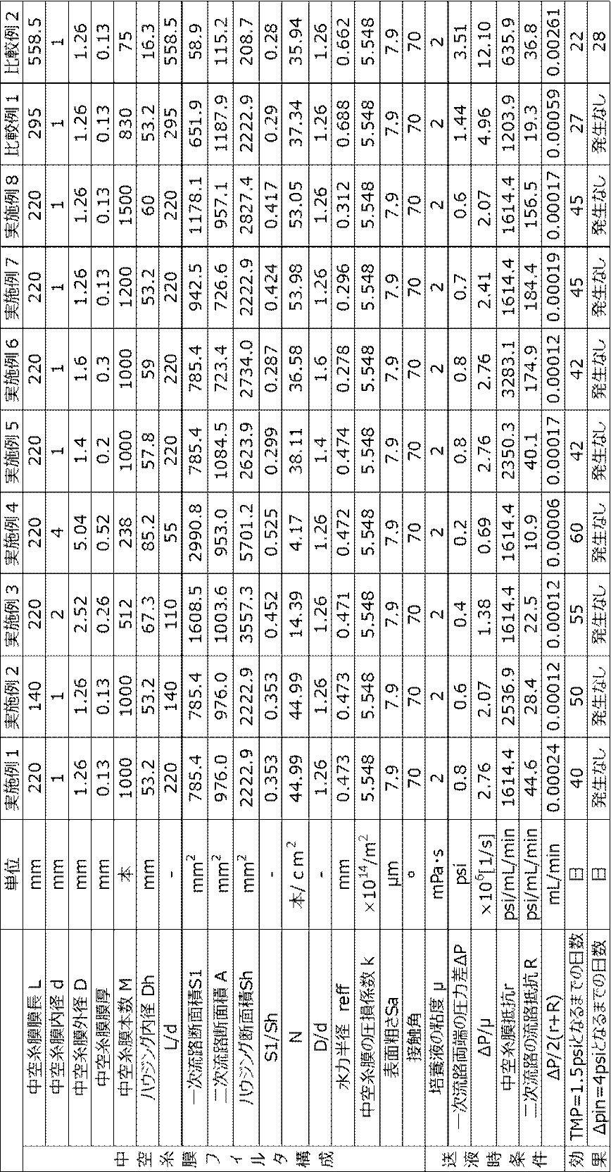
実施例1~8はいずれもS1/Sh≧0.28を満たす。実施例1、3及び4の比較からS1/Shが大きいほど耐用期間を長期間化できることがわかる。
実施例1、5及び6の比較から、D/dが大きいほど耐用期間を長期間化できることがわかる。
実施例1、7及び8の比較から、水力半径reffは0.55以下において小さいほど耐用期間を長期間化できることがわかる。
本明細書に記載された全ての文献、特許出願及び技術規格は、個々の文献、特許出願及び技術規格が参照により取り込まれることが具体的かつ個々に記された場合と同程度に、本明細書中に参照により取り込まれる。
細胞を培養し産生物を得る産生物の製造方法であって、
タンクに収容された培養液中で細胞を培養する培養工程と、
内部に長手方向に延びる一次流路を有する中空糸膜と、複数本の中空糸膜を収容するハウジングとを有し、ハウジング内における各中空糸膜の外部の空間を二次流路とする中空糸膜フィルタを用い、タンクから供給された培養液を、一次流路に送液し、産生物を含む透過液を二次流路に透過させることにより、培養液中の細胞と産生物とを分離する分離工程とを含み、
分離工程において、培養液の送液時における一次流路の供給側と排出側の両端の圧力の差をΔP[Pa]、中空糸膜の膜抵抗を下記式1で表されるr、二次流路の流路抵抗を下記式2で表されるRとした場合に、
培養液の送液時のΔP/2(r+R)を0.0005mL/min以下とする、産生物の製造方法。
r=μk・ln(D/d)/2πL 式1
R=8μLM/πA(reff)2 式2
ここで、kは中空糸膜の圧損係数、Dは中空糸膜の外径、dは中空糸膜の内径、Lは中空糸膜の長さ、Mはハウジングに収容されている中空糸膜の本数、reffは下記式3で表される中空糸膜フィルタの水力半径、Aは中空糸膜フィルタの長さ方向に垂直な断面における二次流路の断面積である。
reff=π(Dh 2-M・D2)/2π(Dh+M・D) 式3
分離工程において、培養液の粘度をμ[Pa・s]とした場合に、培養液の送液時のΔP/μを4.9×106[1/s]以下とする、付記1に記載の産生物の製造方法。
中空糸膜の長さLと、中空糸膜の内径dとの関係が
L/d≦290
を満たす、付記1又は付記2に記載の産生物の製造方法。
中空糸膜フィルタの長さ方向に垂直な断面における一次流路の総断面積S1と、ハウジングの断面積Shとの関係が、
S1/Sh≧0.28
を満たす、付記1から付記3のいずれか1つに記載の産生物の製造方法。
中空糸膜の膜抵抗rが1250psi/mL/min以上である、付記1から付記4のいずれか1つに記載の産生物の製造方法。
中空糸膜の一次流路と二次流路との間の圧損係数kが5×10¹³/m2以上である、付記1から付記5のいずれか1つに記載の産生物の製造方法。
中空糸膜の外径Dと、内径dとの関係が、
D/d≧1.1
を満たす、付記1から付記6のいずれか1つに記載の産生物の製造方法。
中空糸膜の一次流路の壁面の表面粗さがSa=8μm以下である、
付記1から付記7のいずれか1つに記載の産生物の製造方法。
分離工程において、送液の方向を予め設定されたタイミングで逆転させる、付記1から付記8のいずれか1つに記載の産生物の製造方法。
産生物が抗体である、付記1から付記9のいずれか1つに記載の製造方法。
産生物を回収する工程と、
タンクに培地を供給する供給工程と、
を含む、灌流培養である、付記1から付記10のいずれか1つに記載の産生物の製造方法。
培養液の細胞密度が100×106cells/mL以上である、付記1から付記11のいずれか1項に記載の産生物の製造方法。
産生物の力価が1.0g/L以上である、付記1から付記12のいずれか1つに記載の産生物の製造方法。
培養液中で細胞を培養して産生物を得る産生物の製造方法に使用される中空糸膜フィルタであって、
内部に長手方向に延びる一次流路を有する中空糸膜と、
複数本の中空糸膜を収容するハウジングとを有し、
中空糸膜の長さLと、中空糸膜の内径dはそれぞれ、
L≦290mm、d≧1mmであり、
かつ、両者の関係が、
L/d≦290
である、中空糸膜フィルタ。
ハウジングの長さ方向に垂直な断面における1平方センチメートル当たりの中空糸膜の本数Nと、中空糸膜の外径Dとの積N×Dが5本・cm/cm2以上である、付記14に記載の中空糸膜フィルタ。
中空糸膜フィルタの長さ方向に垂直な断面における一次流路の総断面積S1と、ハウジングの断面積Shとの関係が、
S1/Sh≧0.28
を満たす、付記14又は付記15に記載の中空糸膜フィルタ。
中空糸膜の圧損係数kが5×10¹³/m2以上である、付記14から付記16のいずれか1つに記載の中空糸膜フィルタ。
中空糸膜の外径Dと、内径dとの関係が、
D/d≧1.1
を満たす、付記14から付記17のいずれか1つに記載の中空糸膜フィルタ。
ハウジングに収容されている中空糸膜の本数M、ハウジングの内径Dh、及び中空糸膜の外径Dを用いた以下の式で表される水力半径reffが0.55以下である、
reff=π(Dh 2-M・D2)/2π(Dh+M・D)
付記14から付記18のいずれか1つに記載の中空糸膜フィルタ。
中空糸膜の一次流路の壁面の水の接触角が75°以下である、
付記14から付記19のいずれか1つに記載の中空糸膜フィルタ。
培養液中で細胞を培養して産生物を得る産生物の製造方法に使用される産生物の製造装置であって、
培養液を収容するタンクと、
中空糸膜フィルタであって、内部に長手方向に延びる一次流路を有する中空糸膜と、複数本の中空糸膜を収容するハウジングとを有し、中空糸膜の長さLと、中空糸膜の内径dはそれぞれ、
L≦290mm、d≧1mmであり、
かつ、両者の関係が、
L/d≦290
である、中空糸膜フィルタと、
培養液を中空糸膜フィルタの一次流路に送液する第1ポンプと、
中空糸膜フィルタの一次流路に沿って培養液を送液させた場合に、中空糸膜フィルタの二次流路に透過する透過液を産生物回収部に送液する第2ポンプとを備えた、産生物の製造装置。
11:撹拌翼
20:中空糸膜フィルタ
20a:第1開口部
20b:第2開口部
20c:排出口
21:ハウジング
22:中空糸膜
22a:多孔質膜
22h:孔
23:一次流路
24:二次流路
30:培養液
31:培地
32:細胞
33:産生物(抗体)
35:透過液
36:詰まり物質
40:産生物回収部
51~54:管路
61~63:圧力計
70:プロセッサ
100:細胞培養装置
102:簡易実験系
110:容器
120:簡易フィルタ
120A:中空糸膜フィルタ
120B:中空糸膜フィルタ
120a:第1開口部
120b:第2開口部
120c:排出口
121:チューブ
122:中空糸膜
123:一次流路
124:二次流路
130:濾過対象液
151~154:管路
161~163:圧力計
d:中空糸膜の内径
D:中空糸膜の外径
L:中空糸膜の長さ(膜長)
PU1、PU11:第1ポンプ
PU2、PU12:第2ポンプ
PU3、PU13:第3ポンプ
Claims (13)
- 細胞を培養し産生物を得る産生物の製造方法であって、
タンクに収容された培養液中で前記細胞を培養する培養工程と、
内部に長手方向に延びる一次流路を有する中空糸膜と、複数本の前記中空糸膜を収容するハウジングとを有し、前記ハウジング内における各中空糸膜の外部の空間を二次流路とする中空糸膜フィルタを用い、前記タンクから供給された前記培養液を、前記一次流路に送液し、前記産生物を含む透過液を前記二次流路に透過させることにより、前記培養液中の前記細胞と前記産生物とを分離する分離工程とを含み、
前記分離工程において、前記培養液の送液時における前記一次流路の供給側と排出側の両端の圧力の差をΔP[Pa]、前記中空糸膜の膜抵抗を下記式1で表されるr、前記二次流路の流路抵抗を下記式2で表されるRとした場合に、
前記培養液の送液時のΔP/2(r+R)を0.0005mL/min以下とする、産生物の製造方法。
r=μk・ln(D/d)/2πL 式1
R=8μLM/πA(reff)2 式2
ここで、kは前記中空糸膜の圧損係数、Dは前記中空糸膜の外径、dは前記中空糸膜の内径、Lは前記中空糸膜の長さ、Mは前記ハウジングに収容されている前記中空糸膜の本数、reffは下記式3で表される前記中空糸膜フィルタの水力半径、Aは前記中空糸膜フィルタの長さ方向に垂直な断面における前記二次流路の断面積である。
reff=π(Dh 2-M・D2)/2π(Dh+M・D) 式3 - 前記分離工程において、前記培養液の粘度をμ[Pa・s]とした場合に、前記培養液の送液時のΔP/μを4.9×106[1/s]以下とする、請求項1に記載の産生物の製造方法。
- 前記中空糸膜の長さLと、前記中空糸膜の内径dとの関係が
L/d≦290
を満たす、請求項1に記載の産生物の製造方法。 - 前記中空糸膜フィルタの長さ方向に垂直な断面における前記一次流路の総断面積S1と、前記ハウジングの断面積Shとの関係が、
S1/Sh≧0.28
を満たす、請求項1に記載の産生物の製造方法。 - 前記中空糸膜の膜抵抗rが1250psi/mL/min以上である、請求項1に記載の産生物の製造方法。
- 前記中空糸膜の前記一次流路と前記二次流路との間の圧損係数kが5×10¹³/m2以上である、請求項1に記載の産生物の製造方法。
- 前記中空糸膜の外径Dと、内径dとの関係が、
D/d≧1.1
を満たす、請求項1に記載の産生物の製造方法。 - 前記中空糸膜の前記一次流路の壁面の表面粗さがSa=8μm以下である、
請求項1に記載の産生物の製造方法。 - 前記分離工程において、前記送液の方向を予め設定されたタイミングで逆転させる、請求項1から8のいずれか1項に記載の産生物の製造方法。
- 前記産生物が抗体である、請求項1から8のいずれか1項に記載の産生物の製造方法。
- 前記産生物を回収する工程と、
前記タンクに培地を供給する供給工程と、
を含む、灌流培養である、請求項1から8のいずれか1項に記載の産生物の製造方法。 - 前記培養液の細胞密度が30×106cells/mL以上である、請求項1から8のいずれか1項に記載の産生物の製造方法。
- 前記産生物の力価が1.0g/L以上である、請求項1から8のいずれか1項に記載の産生物の製造方法。
Priority Applications (5)
| Application Number | Priority Date | Filing Date | Title |
|---|---|---|---|
| EP24819296.5A EP4711469A1 (en) | 2023-06-09 | 2024-06-03 | Method for producing product |
| KR1020257040939A KR20260007270A (ko) | 2023-06-09 | 2024-06-03 | 산생물의 제조 방법 |
| JP2025526102A JPWO2024253066A1 (ja) | 2023-06-09 | 2024-06-03 | |
| CN202480038202.7A CN121358871A (zh) | 2023-06-09 | 2024-06-03 | 产物制造方法 |
| US19/411,516 US20260091357A1 (en) | 2023-06-09 | 2025-12-08 | Method for manufacturing product |
Applications Claiming Priority (2)
| Application Number | Priority Date | Filing Date | Title |
|---|---|---|---|
| JP2023095895 | 2023-06-09 | ||
| JP2023-095895 | 2023-06-09 |
Related Child Applications (1)
| Application Number | Title | Priority Date | Filing Date |
|---|---|---|---|
| US19/411,516 Continuation US20260091357A1 (en) | 2023-06-09 | 2025-12-08 | Method for manufacturing product |
Publications (1)
| Publication Number | Publication Date |
|---|---|
| WO2024253066A1 true WO2024253066A1 (ja) | 2024-12-12 |
Family
ID=93796010
Family Applications (1)
| Application Number | Title | Priority Date | Filing Date |
|---|---|---|---|
| PCT/JP2024/020229 Ceased WO2024253066A1 (ja) | 2023-06-09 | 2024-06-03 | 産生物の製造方法 |
Country Status (6)
| Country | Link |
|---|---|
| US (1) | US20260091357A1 (ja) |
| EP (1) | EP4711469A1 (ja) |
| JP (1) | JPWO2024253066A1 (ja) |
| KR (1) | KR20260007270A (ja) |
| CN (1) | CN121358871A (ja) |
| WO (1) | WO2024253066A1 (ja) |
Citations (9)
| Publication number | Priority date | Publication date | Assignee | Title |
|---|---|---|---|---|
| JP2000517188A (ja) | 1996-08-30 | 2000-12-26 | ライフ テクノロジーズ,インコーポレイテッド | 無血清哺乳動物細胞培養培地およびその使用 |
| WO2015146990A1 (ja) * | 2014-03-24 | 2015-10-01 | 東レ株式会社 | 分離膜モジュールの運転方法 |
| JP2016215089A (ja) * | 2015-05-15 | 2016-12-22 | 株式会社クラレ | 中空糸膜モジュールの運転方法及び濾過装置 |
| JP2017018940A (ja) * | 2015-07-07 | 2017-01-26 | 株式会社東芝 | 排水処理制御装置及び排水処理システム |
| WO2017057501A1 (ja) * | 2015-10-01 | 2017-04-06 | 住友電気工業株式会社 | 膜分離活性汚泥処理方法及び膜分離活性汚泥処理システム |
| JP2018183150A (ja) | 2012-08-20 | 2018-11-22 | テルモ ビーシーティー、インコーポレーテッド | 細胞成長チャンバーを循環する流体の成分を濃縮する方法 |
| JP2021511202A (ja) | 2018-03-08 | 2021-05-06 | レプリゲン・コーポレイションRepligen Corporation | 接線流深層濾過システムおよびそれを使用する濾過方法 |
| JP2022547907A (ja) * | 2019-09-06 | 2022-11-16 | レプリゲン・コーポレーション | スケールダウンしたタンジェンシャルフロー深層濾過システム、および、それを使用する濾過の方法 |
| JP2023095895A (ja) | 2020-01-31 | 2023-07-06 | トヨタ自動車株式会社 | 車両 |
-
2024
- 2024-06-03 WO PCT/JP2024/020229 patent/WO2024253066A1/ja not_active Ceased
- 2024-06-03 KR KR1020257040939A patent/KR20260007270A/ko active Pending
- 2024-06-03 JP JP2025526102A patent/JPWO2024253066A1/ja active Pending
- 2024-06-03 CN CN202480038202.7A patent/CN121358871A/zh active Pending
- 2024-06-03 EP EP24819296.5A patent/EP4711469A1/en active Pending
-
2025
- 2025-12-08 US US19/411,516 patent/US20260091357A1/en active Pending
Patent Citations (9)
| Publication number | Priority date | Publication date | Assignee | Title |
|---|---|---|---|---|
| JP2000517188A (ja) | 1996-08-30 | 2000-12-26 | ライフ テクノロジーズ,インコーポレイテッド | 無血清哺乳動物細胞培養培地およびその使用 |
| JP2018183150A (ja) | 2012-08-20 | 2018-11-22 | テルモ ビーシーティー、インコーポレーテッド | 細胞成長チャンバーを循環する流体の成分を濃縮する方法 |
| WO2015146990A1 (ja) * | 2014-03-24 | 2015-10-01 | 東レ株式会社 | 分離膜モジュールの運転方法 |
| JP2016215089A (ja) * | 2015-05-15 | 2016-12-22 | 株式会社クラレ | 中空糸膜モジュールの運転方法及び濾過装置 |
| JP2017018940A (ja) * | 2015-07-07 | 2017-01-26 | 株式会社東芝 | 排水処理制御装置及び排水処理システム |
| WO2017057501A1 (ja) * | 2015-10-01 | 2017-04-06 | 住友電気工業株式会社 | 膜分離活性汚泥処理方法及び膜分離活性汚泥処理システム |
| JP2021511202A (ja) | 2018-03-08 | 2021-05-06 | レプリゲン・コーポレイションRepligen Corporation | 接線流深層濾過システムおよびそれを使用する濾過方法 |
| JP2022547907A (ja) * | 2019-09-06 | 2022-11-16 | レプリゲン・コーポレーション | スケールダウンしたタンジェンシャルフロー深層濾過システム、および、それを使用する濾過の方法 |
| JP2023095895A (ja) | 2020-01-31 | 2023-07-06 | トヨタ自動車株式会社 | 車両 |
Also Published As
| Publication number | Publication date |
|---|---|
| CN121358871A (zh) | 2026-01-16 |
| KR20260007270A (ko) | 2026-01-13 |
| US20260091357A1 (en) | 2026-04-02 |
| JPWO2024253066A1 (ja) | 2024-12-12 |
| EP4711469A1 (en) | 2026-03-18 |
Similar Documents
| Publication | Publication Date | Title |
|---|---|---|
| TWI675696B (zh) | 用於灌注應用之切向流過濾裝置 | |
| JP7043125B2 (ja) | 連続培養における有用物質の回収方法 | |
| JP6869423B2 (ja) | 生産物の製造方法 | |
| CN111902197B (zh) | 切向流深度过滤系统和使用其进行过滤的方法 | |
| WO2018159847A1 (ja) | 細胞培養装置及び細胞培養方法 | |
| US11667672B2 (en) | Methods, devices and systems for 3-stage filtration | |
| US20210087512A1 (en) | Cell culture system and cell culture method | |
| CN113355242B (zh) | 灌流模块及灌流培养系统 | |
| CN112584916A (zh) | 用于过滤的系统和其相关联的方法 | |
| JP7330834B2 (ja) | 培養方法および培養装置 | |
| WO2024253066A1 (ja) | 産生物の製造方法 | |
| US12252680B2 (en) | Bioreactor with filter unit and method for treating a cell broth | |
| WO2024253065A1 (ja) | 産生物の製造方法、中空糸膜フィルタ及び産生物の製造装置 | |
| KR20210096671A (ko) | 소수성 중공 섬유에 의한 포유류 세포 배양물의 관류 및 정화용 필터 | |
| JP2014024824A (ja) | 潅流培養における有用タンパク質を含む培養液の濾過方法 | |
| JP2023180074A (ja) | 粒子分離システム | |
| JPH01206988A (ja) | 培養装置 |
Legal Events
| Date | Code | Title | Description |
|---|---|---|---|
| 121 | Ep: the epo has been informed by wipo that ep was designated in this application |
Ref document number: 24819296 Country of ref document: EP Kind code of ref document: A1 |
|
| DPE1 | Request for preliminary examination filed after expiration of 19th month from priority date (pct application filed from 20040101) | ||
| ENP | Entry into the national phase |
Ref document number: 2025526102 Country of ref document: JP Kind code of ref document: A |
|
| WWE | Wipo information: entry into national phase |
Ref document number: 2025526102 Country of ref document: JP |
|
| ENP | Entry into the national phase |
Ref document number: 1020257040939 Country of ref document: KR Free format text: ST27 STATUS EVENT CODE: A-0-1-A10-A15-NAP-PA0105 (AS PROVIDED BY THE NATIONAL OFFICE) |
|
| WWE | Wipo information: entry into national phase |
Ref document number: 1020257040939 Country of ref document: KR |
|
| WWE | Wipo information: entry into national phase |
Ref document number: 2024819296 Country of ref document: EP |
|
| ENP | Entry into the national phase |
Ref document number: 2024819296 Country of ref document: EP Effective date: 20251209 |
|
| ENP | Entry into the national phase |
Ref document number: 2024819296 Country of ref document: EP Effective date: 20251209 |
|
| ENP | Entry into the national phase |
Ref document number: 2024819296 Country of ref document: EP Effective date: 20251209 |
|
| ENP | Entry into the national phase |
Ref document number: 2024819296 Country of ref document: EP Effective date: 20251209 |
|
| NENP | Non-entry into the national phase |
Ref country code: DE |
|
| ENP | Entry into the national phase |
Ref document number: 2024819296 Country of ref document: EP Effective date: 20251209 |
|
| WWP | Wipo information: published in national office |
Ref document number: 1020257040939 Country of ref document: KR |
|
| ENP | Entry into the national phase |
Ref document number: 2024819296 Country of ref document: EP Effective date: 20251209 |
|
| ENP | Entry into the national phase |
Ref document number: 2024819296 Country of ref document: EP Effective date: 20251209 |
|
| ENP | Entry into the national phase |
Ref document number: 2024819296 Country of ref document: EP Effective date: 20251209 |
|
| ENP | Entry into the national phase |
Ref document number: 2024819296 Country of ref document: EP Effective date: 20251209 |
|
| WWP | Wipo information: published in national office |
Ref document number: 2024819296 Country of ref document: EP |