WO2024252990A1 - 自動分析装置、自動分析方法および圧力センサユニットの製膜方法 - Google Patents
自動分析装置、自動分析方法および圧力センサユニットの製膜方法 Download PDFInfo
- Publication number
- WO2024252990A1 WO2024252990A1 PCT/JP2024/019593 JP2024019593W WO2024252990A1 WO 2024252990 A1 WO2024252990 A1 WO 2024252990A1 JP 2024019593 W JP2024019593 W JP 2024019593W WO 2024252990 A1 WO2024252990 A1 WO 2024252990A1
- Authority
- WO
- WIPO (PCT)
- Prior art keywords
- hydrophilic film
- pressure sensor
- sensor unit
- automatic analyzer
- dispensing
- Prior art date
- Legal status (The legal status is an assumption and is not a legal conclusion. Google has not performed a legal analysis and makes no representation as to the accuracy of the status listed.)
- Ceased
Links
Images










Classifications
-
- G—PHYSICS
- G01—MEASURING; TESTING
- G01N—INVESTIGATING OR ANALYSING MATERIALS BY DETERMINING THEIR CHEMICAL OR PHYSICAL PROPERTIES
- G01N35/00—Automatic analysis not limited to methods or materials provided for in any single one of groups G01N1/00 - G01N33/00; Handling materials therefor
- G01N35/10—Devices for transferring samples or any liquids to, in, or from, the analysis apparatus, e.g. suction devices, injection devices
- G01N35/1009—Characterised by arrangements for controlling the aspiration or dispense of liquids
- G01N35/1016—Control of the volume dispensed or introduced
-
- B—PERFORMING OPERATIONS; TRANSPORTING
- B01—PHYSICAL OR CHEMICAL PROCESSES OR APPARATUS IN GENERAL
- B01L—CHEMICAL OR PHYSICAL LABORATORY APPARATUS FOR GENERAL USE
- B01L2300/00—Additional constructional details
- B01L2300/16—Surface properties and coatings
- B01L2300/161—Control and use of surface tension forces, e.g. hydrophobic, hydrophilic
Definitions
- the present invention relates to an automatic analysis device, an automatic analysis method, and a film manufacturing method for a pressure sensor unit.
- Automatic analyzers that analyze blood and other components in the body to find abnormal values in biological components and to analyze biological components that can determine the presence or absence of disease are used in hospitals and many medical research institutions.
- Automatic analyzers are equipped with a dispensing mechanism that transfers liquid samples from sample containers or reagent containers to reaction containers where the samples and reagents are mixed in the appropriate ratios by a suction and discharge operation known as dispensing.
- the dispensing flow path is usually filled with a liquid such as purified water (hereinafter referred to as system water) in order to accurately transmit the pressure generated by the pressure generating means inside the dispensing mechanism, such as a syringe or diaphragm.
- system water purified water
- the dispensing mechanism is equipped with a pressure sensor unit to realize dispensing with this high dispensing accuracy.
- the pressure sensor unit consists of a sensor section that measures pressure with a diaphragm, and a connecting container that branches the system water from the pressure-receiving surface of the diaphragm towards the dispensing nozzle and towards the syringe. Since the pressure sensor unit measures pressures in the range of approximately -100 to 100 kPa with high sensitivity, the diameter of the diaphragm attached to its tip needs to be large. Specifically, the diameter of the diaphragm is approximately 10 to 15 mm. Also, the diameter of the pipe (flow path) connected to the connecting container of the pressure sensor unit is a few mm, which is smaller than the diaphragm.
- Patent Document 1 describes a method of creating a structure that removes air bubbles by locating one of the two liquid inlet/outlet ports in the connecting container of the pressure sensor unit near the diaphragm and making the system water move in a swirling manner near the diaphragm surface as it flows into the connecting container. By adopting this structure, air bubbles inside the pressure sensor unit are removed to a certain extent.
- Patent Document 1 Even when the technology of Patent Document 1 is applied, air bubbles remain inside the pressure sensor unit due to its structure, which can reduce the accuracy of pressure measurement. For this reason, although it is currently desirable to improve the structure, it is often difficult to change the structure when using general-purpose products.
- the present invention has been made in consideration of the above situation.
- the object of the present invention is to provide an automatic analysis device, an automatic analysis method, and a film manufacturing method for a pressure sensor unit that do not leave any air bubbles inside.
- FIG. 11 is a schematic cross-sectional view showing yet another example of a pressure sensor unit in an automatic analyzer according to one embodiment of the present invention.
- FIG. FIG. 2 is a cross-sectional view (SEM image) of a hydrophilic film containing silica particles and a silica binder.
- 1 is a graph showing the relationship between the film thickness (nm) of a hydrophilic film and the contact angle (°) with water.
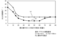
- 1 is a graph showing the relationship between the proportion (mass %) of silica particles in a hydrophilic film and the contact angle (°) with water.
- 1 is a graph showing the relationship between the proportion (mass%) of SiO 2 particles in a hydrophilic film and the contact angle (°) with water.
- FIG. 2 is a schematic diagram of a cross section of a roughened surface on which a hydrophilic film is formed.
- FIG. 2 is a schematic diagram of a cross section of a roughened surface on which a hydrophilic film is formed.
- FIG. 2 is a schematic diagram of a cross section of a roughened surface on which a hydrophilic film is formed.
- 11A to 11C are explanatory diagrams illustrating a process of forming a hydrophilic film on the inner surface of a connecting container.
- 11A to 11C are explanatory diagrams illustrating a process of forming a hydrophilic film on the inner surface of a connecting container
- 11A to 11C are explanatory diagrams illustrating a process of forming a hydrophilic film on the inner surface of a connecting container.
- FIG. 13 is an explanatory diagram showing a cut portion when measuring the surface roughness of the inner surface of a connecting container.
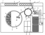
- FIG. 1 is an explanatory diagram showing an example of the overall configuration of an automatic analysis apparatus according to one embodiment of the present invention.
- Fig. 2 is an explanatory diagram showing another example of the overall configuration of an automatic analysis apparatus according to one embodiment of the present invention.
- the automatic analyzer 1 reacts a specimen sample with a reagent to analyze a specific component in the specimen.
- the automatic analyzer 1 generally comprises a reagent container loading section 3 in which reagent containers 2 filled with reagent are loaded, a reagent cooler 4 that contains the reagent container loading section 3, and a rack transport line 7 which is a transport line for racks 6 on which sample containers 5 holding samples are installed.
- the automated analyzer 1 is also provided with a circular incubator disk 9 capable of accommodating many reaction vessels 8, a sample dispensing nozzle 10 which is a nozzle for dispensing samples, a reagent dispensing nozzle 11 which is a nozzle for dispensing reagents, and a reaction vessel transport mechanism 12 which is a mechanism for transporting the reaction vessels 8.
- multiple reaction vessels 8 can be installed on the incubator disk 9.
- the incubator disk 9 is attached so that the reaction vessels 8 installed in the circumferential direction can be moved to their respective predetermined positions by rotating.
- the rack 6 is fitted with a sample container 5 for holding samples as described above, and the rack transport line 7 moves the sample container 5 to a sample dispensing position 13 near the sample dispensing nozzle 10.
- a sample dispensing tip/reaction vessel transport mechanism 14 is installed near the incubator disk 9 so that it can move in three directions: the X-axis, Y-axis, and Z-axis.
- the sample dispensing tip/reaction vessel transport mechanism 14 is attached so that it can move within the range of the sample dispensing tip/reaction vessel holding member 15, reaction vessel stirring mechanism 16, sample dispensing tip/reaction vessel disposal hole 17, sample dispensing tip mounting position 18, and specified locations on the incubator disk 9, thereby transporting the sample dispensing tip and reaction vessel 8.
- the sample dispensing tip/reaction vessel holding member 15 is equipped with a number of unused reaction vessels 8 and sample dispensing tips. Therefore, the sample dispensing tip/reaction vessel transport mechanism 14 moves above the sample dispensing tip/reaction vessel holding member 15, then descends to grab an unused reaction vessel 8 and then rises. The sample dispensing tip/reaction vessel transport mechanism 14 then moves above a predetermined position on the incubator disk 9, then descends to attach the unused reaction vessel 8 to the incubator disk 9.
- the sample dispensing tip/reaction vessel transport mechanism 14 also moves above the sample dispensing tip/reaction vessel holding member 15, then descends to grab an unused sample dispensing tip and rises.
- the sample dispensing tip/reaction vessel transport mechanism 14 also moves above the sample dispensing tip mounting position 18, then descends to place the sample dispensing tip at the sample dispensing tip mounting position 18.
- the sample dispensing nozzle 10 can also rotate and move up and down.
- the sample dispensing nozzle 10 rotates and moves above the sample dispensing tip attachment position 18, then descends to attach a sample dispensing tip to the tip of the sample dispensing nozzle 10.
- the sample dispensing nozzle 10 with the sample dispensing tip attached then moves above the sample container 5 held in the rack 6, then descends to aspirate a predetermined amount of sample held in the sample container 5.
- the sample dispensing nozzle 10 that has aspirated the sample moves above the incubator disk 9 and then descends to dispense the sample into an unused reaction vessel 8 held by the incubator disk 9.
- the sample dispensing nozzle 10 When the sample dispensing nozzle 10 has completed dispensing the sample, it discards the sample dispensing tip from the sample dispensing tip/reaction vessel disposal hole 17.
- a plurality of reagent containers 2 are loaded into the reagent container loading section 3 disposed inside the reagent refrigerator 4. Furthermore, a lid 19 for the reagent refrigerator 4 is provided on the top of the reagent container loading section 3, and the inside of the reagent refrigerator 4 can be kept at a predetermined temperature.
- the lid 19 does not cover a portion of the refrigerator, but this portion has a loader (not shown in FIG. 1) for lifting the reagent container loading section 3 upward to insert and remove it.
- a part of the lid 19 is provided with a reagent suction hole 20 which is a through hole for suctioning a reagent.
- the reagent dispensing nozzle 11 can rotate and move up and down, and rotates to above the reagent suction hole 20 provided in the lid 19 of the reagent cooler 4, and then descends and passes through the reagent suction hole 20.
- the tip of the reagent dispensing nozzle 11 which has passed through the reagent suction hole 20 is inserted into the reagent in a predetermined reagent container 2, and a predetermined amount of reagent is aspirated.
- the reagent dispensing nozzle 11 rises and rotates to move above a predetermined position on the incubator disk 9, and dispenses the reagent into a reaction container 8 placed on the incubator disk 9.
- the reaction vessel 8 into which the sample and reagent have been dispensed is moved to a prescribed position by the rotation of the incubator disk 9, and is then transported to the reaction vessel stirring mechanism 16 by the sample dispensing tip/reaction vessel transport mechanism 14.
- the reaction vessel stirring mechanism 16 stirs and mixes the sample and reagent in the reaction vessel 8 by applying a rotational motion to the reaction vessel 8. After stirring, the reaction vessel 8 is returned to its prescribed position on the incubator disk 9 by the sample dispensing tip/reaction vessel transport mechanism 14.
- the reaction vessel transport mechanism 12 is capable of rotating and moving up and down, and moves above the reaction vessel 8 after the dispensing and mixing of the sample and reagent has been completed and a predetermined reaction time has elapsed on the incubator disk 9, and then moves down to hold the reaction vessel 8. Thereafter, the reaction vessel 8 is transported by the rotational movement of the reaction vessel transport mechanism 12 to the detection unit 21, where the analysis result of the specific component in the sample is determined.
- the drive and drive timing of the various components described above are controlled by a control unit 103 (see FIGS. 3 and 4), such as a personal computer of the automatic analyzer 1, not shown in FIG.
- this automatic analyzer 22 is a type that does not have tips attached to the ends of the sample dispensing nozzle 23 and the reagent dispensing nozzle 24. After the automatic analyzer 22 has finished aspirating and discharging the sample and reagent through these nozzles, instead of replacing the tips, it inserts the tips into a nozzle cleaning mechanism 25 for cleaning the nozzle tips and cleans them. In addition, in this automatic analyzer 22, the color intensity, turbidity, etc. of the reagent/sample mixture in the reaction vessel 8 are quantified by the measurement unit 26.
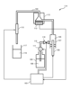
- the dispensing mechanism 100 includes a dispensing nozzle 102 (corresponding to the sample dispensing nozzle 10 and reagent dispensing nozzle 11) that dispenses a sample and reagent equipped with a detachable tip 101 (corresponding to the sample dispensing tip and tip described above), and performs the operations described in FIG. 1. This is controlled by a control unit 103.
- the dispensing nozzle 102 is connected to the syringe 105 via the flow path 104, and the inside of the syringe 105 is filled with system water 106.
- the syringe 105 has a cylinder 107 and a plunger 108.
- the drive of the plunger 108 is controlled by the control unit 103.
- the control unit 103 drives the plunger 108 in the vertical direction relative to the syringe 105, thereby aspirating and discharging a liquid sample or liquid reagent in the tip 101 attached to the dispensing nozzle 102.
- the syringe 105 has a flow path 118 that communicates with the water supply tank 109.
- This flow path 118 is provided with an electromagnetic valve 110 and a water supply pump 111, which is a pressure generating means.
- the water supply tank 109 stores system water 106, and the inside of the dispensing nozzle 102 can be washed by discharging the system water 106 from the dispensing nozzle 102 by driving the water supply pump 111. This cleaning is performed before dispensing the sample or reagent, which minimizes contamination of the dispensing nozzle 102 during dispensing from being mixed into the sample or reagent.
- the pressure sensor unit 112 is located in the flow path 104 between the dispensing nozzle 102 and the syringe 105.
- the pressure sensor unit 112 measures the pressure in the flow path 104, including the nozzle (dispensing nozzle 102) and the pressure generating means (water supply pump 111), using a pressure sensor 113, and sends the result to the control unit 103.
- a dispensing mechanism 114 shown in FIG. 4 has many parts in common with the dispensing mechanism 100 shown in FIG. 3, so only the different parts will be described.
- this dispensing mechanism 114 is a type that does not have a tip attached to the end of the dispensing nozzle 115. After the dispensing nozzle 115 has finished aspirating and dispensing a sample or reagent, the tip is not replaced, but instead the nozzle tip is washed by inserting it into a nozzle washing mechanism 117 containing washing water 116 for washing the nozzle tip.
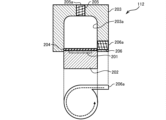
- FIG. 5 is a schematic cross-sectional view showing an example of a pressure sensor unit in an automatic analyzer according to one embodiment of the present invention.
- Fig. 6 is a schematic cross-sectional view showing another example of a pressure sensor unit in an automatic analyzer according to one embodiment of the present invention.
- Fig. 7 is a schematic cross-sectional view showing yet another example of a pressure sensor unit in an automatic analyzer according to one embodiment of the present invention.
- the pressure sensor unit 112 shown in FIG. 5 is located in the flow path 104 between the dispensing nozzle 102 (dispensing nozzle 115) and the syringe 105, as described with reference to FIGS. 3 and 4.
- the pressure sensor unit 112 is configured to include a pressure sensor 202 having a diaphragm 201 that measures pressure, and a connection container 203 that is the housing of the pressure sensor unit 112.
- an O-ring 204 is attached between the pressure sensor 202 and the connection container 203 to prevent the system water 106 from leaking.
- the pressure resistance is further improved by designing the O-ring 204 to fit inside the connection container 203.
- a hydrophilic film 305 (see Figures 8 and 12) containing silica particles or alumina particles and a silicon compound, or consisting of silica particles or alumina particles and a silicon compound, is formed on the inner surface 203a of the pressure sensor unit 112 (specifically, of the connection container 203).
- the inner surface 203a of the pressure sensor unit 112 hydrophilic with the hydrophilic film 305, the inner surface 203a becomes an air-repellent surface that has an affinity for water and repels air. As a result, air bubbles no longer adhere to the inner surface, and the bubble-free process progresses.
- the relationship between the arithmetic mean roughness Ra0 of the base material 301 of the inner surface 203a (see FIG. 8 and FIG. 12A-C) and the arithmetic mean roughness Ra1 of the inner surface 203a after the hydrophilic film 305 is formed is 0.8 ⁇ Ra0 ⁇ Ra1.
- 0.85 ⁇ Ra0 ⁇ Ra1 is preferable, 0.9 ⁇ Ra0 ⁇ Ra1 is more preferable, 0.95 ⁇ Ra0 ⁇ Ra1 is even more preferable, and 0.97 ⁇ Ra0 ⁇ Ra1 is even more preferable.
- connection parts 205, 206 of the flow path 104 from the dispensing nozzle 102 (dispensing nozzle 115) and the syringe 105 to the pressure sensor unit 112 each have an inlet/outlet 205a, 206a through which the system water 106 flows into or out of the pressure sensor unit 112.
- the openings of the inlet/outlet 205a, 206a communicate with the opening of the flow path 104.
- the connection parts 205, 206 shown in FIG. 5 are screwed into the flow path 104, but they can be connected to the flow path 104 by any pressure-resistant connection method, such as pushing.
- the inner shape of the pressure sensor unit 112 (the inner shape of the connection container 203) is conical, and is installed so that the apex of the cone is vertically upward.
- a liquid inlet/outlet 205a that connects to a nozzle (dispensing nozzle 102) is provided at the apex of the cone (upper diagram in Figure 5).
- a liquid inlet/outlet 206a that connects to a pressure generating means (water supply pump 111) is provided in the tangential direction of the bottom peripheral surface of the cone (lower diagram in Figure 5).
- the pressure receiving surface (diaphragm 201) of the pressure sensor unit 112 is located at the bottom surface of the cone.
- the system water 106 that flows into the connection container 203 from the inlet/outlet 206a provided in the tangential direction of the bottom peripheral surface flows toward the inlet/outlet 205a at the apex while generating a swirling flow along the peripheral surface inside the connection container 203, and flows out from the inlet/outlet 205a at the apex.
- the pressure sensor unit 112 removes air bubbles from inside the connection container 203 due to this swirling flow.
- connection container 203 should be made of a resin such as acrylic or polycarbonate.
- a block of resin can be molded by machining.
- the block itself should be submerged in water while processing, or water should be thoroughly dispersed on the block surface while processing while cooling.
- Ra arithmetic mean roughness
- a hydrophilic film 305 is formed on the conical inner surface 203a of the connection container 203, and air bubbles inside the connection container 203 are removed, thereby reducing the retention of air bubbles inside the connection container 203, thereby further improving the accuracy of pressure measurement by the diaphragm 201.
- the shape of the pressure sensor unit 112 (the shape of the connecting container 203) is not limited to the conical shape shown in FIG. 6, the pressure sensor unit 112 may have a structure in which the inside of the connection container 203 is a cone and a cylinder connected together. In this case, the inlet/outlet 206a may be formed in the cylinder portion rather than the cone portion. This has the advantage that the inlet/outlet 206a can be formed more easily in the cylinder portion than in the cone portion. 7, the pressure sensor unit 112 may have a structure in which the inside of the connection container 203 is cylindrical and the upper corners are rounded. Even in the case of such a rounded structure, it is possible to prevent air bubbles from remaining at the upper corners.
- the hydrophilic film 305 in this embodiment is produced by applying the hydrophilic film coating liquid that forms this film to the inside of the connection container 203 and then curing it.
- the material composition of the hydrophilic film coating liquid specifically consists of at least one of particles (silica particles) made of silicon dioxide (silica) and particles (alumina particles) made of aluminum trioxide (alumina) as hydrophilic materials, a binder that holds these particles, and an organic solvent that disperses or dissolves them.
- the binder is preferably an alkoxysilane compound whose main component becomes silica when heated.
- the hydrophilicity of the hydrophilic film 305 is improved by specifying the size of the silica particles or alumina particles, which contributes to a more bubble-free structure. Also, the hydrophilicity of the hydrophilic film 305 is improved by specifying the addition rate of the silica particles or alumina particles, which contributes to a more bubble-free structure.
- FIG. 8 is a cross-sectional view (scanning electron microscope image (SEM image)) of a hydrophilic film containing silica particles and a silica binder.
- the hydrophilic film 305 shown in FIG. 8 uses silica particles 302 as a hydrophilic material. As shown in FIG. 8, the hydrophilic film 305 is formed on the substrate 301.
- the hydrophilic film 305 includes silica particles 302, silica binders 304 (see FIGS. 12A to 12C), and voids 303 between the particles.
- the silica binders 304 are thinly attached between the silica particles 302 and to the substrate 301 to maintain the structure of the film.
- the contact angle of silica itself with water is about 30°, but the contact angle with water is reduced by the fine irregularities of the silica particles 302 on the surface of the hydrophilic film 305 and the voids 303 on the surface. Furthermore, the contact angle of the hydrophilic film 305 surface with water is further reduced by the gaps between the silica particles 302 and the voids 303 due to the capillary phenomenon, as condensed water seeps into them. This makes it possible to form the hydrophilic film 305 with a contact angle with water of 15° or less. It should be noted that even if alumina particles are used in place of the silica particles 302, a similar film structure is obtained, and similar effects are obtained.
- This coating solution for hydrophilic film is prepared by dispersing and dissolving at least one of silica particles and alumina particles and a precursor of a silica binder in an organic solvent.
- the organic solvent is an alcohol-based solvent.
- b-1) Hydrophilic Material In this embodiment, at least one of silica particles and alumina particles is used as the hydrophilic material.
- the average particle size of these particles is preferably 10 to 50 nm, more preferably 10 to 20 nm. The reasons for this are as follows. The average particle size of these particles can be measured using a particle size analyzer LA-950V2 manufactured by Horiba, Ltd.
- ⁇ Hydrophilicity The hydrophilicity of silica particles and alumina particles is exerted by the surface of the particles. For example, in the case of silica particles, some of the bonds between silicon and oxygen are broken, exposing hydroxyl groups, which is thought to exert hydrophilicity. In the case of alumina, some of the bonds between aluminum and oxygen are broken, exposing hydroxyl groups, which is thought to exert hydrophilicity. Therefore, the larger the surface area of the particles per unit mass, the more the number of hydroxyl groups exposed on the surface per unit mass increases, improving hydrophilicity. The smaller the particle size, the larger the surface area per unit mass, and the stronger the hydrophilicity.
- ⁇ Dispersion stability in hydrophilic film coating solution The density of these particles is 2.5 to 2.6 g/ cm3 for silica particles and 3.9 to 4.1 g/ cm3 for alumina particles, which is considerably larger than the 0.8 to 1.0 g/ cm3 for the solvent described below. Therefore, if the particle diameter of these particles is large, they will settle in the hydrophilic film coating liquid. In terms of size, settling becomes noticeable when the silica particles are 70 nm or more, and when the alumina particles are 50 nm or more. Therefore, when the particle diameter is large, it is necessary to stir the particles before use and disperse them throughout the hydrophilic film coating liquid before use. For the above reasons, the average particle diameter of the preferred particles is 50 nm or less.
- the particle shape is spherical, but some particles have a shape in which several to several tens of spherical particles are connected together.
- the size of each spherical particle is 50 nm or less, dispersibility is sufficient and this is preferable. From this perspective, and for the reasons stated above, the preferred average particle size is 50 nm or less.
- ⁇ Leveling ability on substrate When coated on a substrate 301 having an uneven surface, the particles fill in the valleys to some extent, so the surface unevenness is reduced. This can be confirmed by a decrease in the arithmetic surface roughness (Ra).
- Ra arithmetic surface roughness
- the actual surface area is decreased, so the number of hydroxyl groups derived from silica particles or alumina particles per unit area of the projected area is decreased, and there is a possibility that the desired hydrophilicity cannot be obtained.
- the average particle diameter is 10 to 20 nm
- the effect of filling the valleys is slight, and the coating is performed along the shape of the unevenness without filling the valleys, so there is almost no change in Ra and it is possible to impart high hydrophilicity.
- a more preferable average particle diameter is 10 to 20 nm.
- the average particle size of the silica particles and alumina particles used is preferably 10 nm or more. From this point of view, the preferred average particle size is 10 nm or more for the above reasons.
- the hydrophilic film 305 is a binder whose main component after film formation is silica.
- Silica is insoluble in organic solvents, but some of its precursors are soluble in organic solvents.
- a silica precursor that is soluble in organic solvents is used.
- silica precursors include hydrolyzable silicon compounds that change into silica through hydrolysis.
- the most common hydrolyzable silicon compound is usually called silica sol. This is a polymer formed when multiple tetraalkoxysilanes are partially hydrolyzed, the alkoxy groups are removed, and multiple molecules form silicon-oxygen-silicon bonds to form a polymer with an average molecular weight of several thousand to tens of thousands.
- Silica sol is soluble in alcohol-based solvents such as methanol and ethanol.
- Tetraethoxysilane is the easiest to use tetraalkoxysilane.
- Tetramethoxysilane which has a shorter alkyl chain than tetraethoxysilane, is highly reactive with water, so if stored for a long period of time in a high humidity environment, the hydrophilic film coating liquid that forms the hydrophilic film 305 may harden.
- tetrapropoxysilane and tetrabutoxysilane which have longer alkyl chains than tetraethoxysilane, are less likely to undergo hydrolysis reactions, so there is a tendency for the heat-curing time after application to be longer, and for the heat-curing reaction to proceed slowly unless the heating temperature is high. Therefore, tetraethoxysilane is the preferred tetraalkoxysilane for forming silica sol.
- silica sol which is a polymer of alkoxysilane
- compounds that have three alkoxy groups on a silicon atom with four bonding groups in the molecule, as well as other bonding groups other than alkoxy groups, such as a benzene ring or an alkyl chain can also be used as precursors for the silica binder 304.
- this material although the main component of the hydrophilic film 305 is silica, it will also contain atoms such as carbon, nitrogen, and sulfur.
- Such compounds include methyltrimethoxysilane, dimethyldimethoxysilane, phenyltrimethoxysilane, phenyltriethoxysilane, methyltriethoxysilane, n-propyltrimethoxysilane, n-propyltriethoxysilane, vinyltrimethoxysilane, vinyltriethoxysilane, 3-aminopropyltrimethoxysilane, 3-aminopropyltriethoxysilane, N-2-(aminoethyl)-3-aminopropyltrimethoxysilane, N-2-(aminoethyl)-3-aminopropyltriethoxysilane, 3-isocyanatepropyltrimethoxysilane, 3-isocyanatepropyltriethoxysilane, 3-mercaptopropyltrimethoxysilane, and 3-mercaptopropyltriethoxysilane.
- Solvent A normal organic solvent is used as the solvent for the hydrophilic film coating solution.
- resins such as acrylic and polycarbonate are often used for the connection container 203, which is the housing of the pressure sensor unit 112, because of ease of machining.
- these resins may dissolve or swell depending on the type of solvent. Therefore, an alcohol-based solvent is preferable because it does not dissolve or swell these resins, or does not do so much.
- methanol, ethanol, 1-propanol, 2-propanol, 1-butanol, 2-butanol, tert-butanol, and the like, each having 1 to 4 carbon atoms, are preferable.
- solvents have a boiling point of about 60 to 120°C, so they volatilize quickly after coating, and have the advantage of being able to shorten the time required for film formation. If the number of carbon atoms is greater than butanol, it becomes difficult to dissolve hydrolyzable silicon compounds, and moreover, it takes a long time to dry after application, so alcohols with 5 or more carbon atoms are not preferable.
- cellosolve-based solvents in which one of the hydroxyl groups in ethylene glycol is a monoalkoxy group, are also suitable because they easily dissolve hydrolyzable silicon compounds.
- FIG. 9 is a graph showing the relationship between the thickness (nm) of the hydrophilic film and the contact angle (°) with water.
- the graph in FIG. 9 shows the results of forming a hydrophilic film 305 using a hydrophilic film coating solution with a mass ratio of silica particles 302 to silica precursor of 1:1.
- the substrate 301 is an acrylic plate with an arithmetic surface roughness (Ra) of 10 nm and is visually flat.
- Ra arithmetic surface roughness
- the thickness of the hydrophilic film 305 is 50 nm or more, the contact angle with water decreases to 10°, and higher hydrophilicity is exhibited.
- the thickness of the hydrophilic film 305 in this embodiment is preferably 50 nm or more. The thickness can be measured at multiple arbitrary points and managed by averaging the thicknesses (average thickness).
- the solid content in the hydrophilic film coating solution that forms the hydrophilic film 305 is at least one of the hydrophilic materials, silica particles 302 and alumina particles, and a silica precursor that is a binder. If the ratio of these two is different, the performance of the hydrophilic film 305, that is, the contact angle with water, changes.
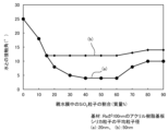
- the contact angle with water of the hydrophilic film 305 formed to a film thickness of approximately 100 nm by changing the ratio of the silica particles 302 and the silica precursor was investigated. The results are shown in FIG. 10.
- FIG. 10 is a graph showing the relationship between the proportion (mass %) of silica particles in a hydrophilic film and the contact angle (°) with water.
- the horizontal axis in Fig. 10 indicates the proportion of silica particles 302.
- the proportion of the precursor of the silica binder 304 is a value obtained by subtracting the proportion of the silica particles 302 from 100%.
- the average particle diameter of the silica particles 302 used here was 20 nm.
- the average particle diameter of the silica particles 302 was measured with a particle size analyzer LA-950V2 manufactured by Horiba, Ltd.
- the contact angle was measured with a contact angle meter (model: CA-D) manufactured by Kyowa Interface Science Co., Ltd.
- the contact angle with water decreases as the content of hydrophilic silica particles 302 increases.
- the contact angle decreased to 10° when the content of silica particles 302 was 30% by mass or more.
- the contact angle remained constant when the content of silica particles 302 was 30 to 90% by mass, and did not decrease any further.
- the contact angle was even lower than when the Ra was 5 nm.
- the contact angle was reduced to 4 to 5°. In other words, the hydrophilicity was improved when the film was formed on a substrate with a larger Ra.
- the Ra of the hydrophilic film 305 after formation was measured, the Ra of the hydrophilic film 305 containing 30 mass% silica particles 302 with an average particle size of 20 nm was 92 nm.
- the Ra of the hydrophilic film 305 containing 60 mass% silica particles 302 was 82 nm.
- the Ra of the hydrophilic film 305 containing 65 mass% silica particles 302 was 61 nm. From these findings, it was found that the increase in the proportion of silica particles 302 and the decrease in Ra were the factors that increased the contact angle. From the viewpoint of obtaining sufficient hydrophilicity, it can be said that it is preferable that the Ra of the hydrophilic film 305 is 80 nm or more (0.08 ⁇ m or more).
- the content of the silica particles 302, which is a hydrophilic material, in the solid content in the hydrophilic film coating liquid is preferably 30 to 60 mass %.
- a similar experiment was also carried out using alumina particles (average particle diameter: 20 nm), and it was found that the particle content is preferably 30 to 60 mass %, similar to the silica particles 302.
- the average particle diameter of the alumina particles was also measured using a particle size analyzer LA-950V2 manufactured by Horiba, Ltd.
- a hydrophilic film 305 was formed on an acrylic plate having an Ra of 100 nm using two types of silica particles 302 having average particle sizes of 20 nm and 50 nm, and the same experiment as above was performed.
- the results are shown in FIG. FIG. 11 is a graph showing the relationship between the proportion (mass %) of SiO 2 particles in a hydrophilic film and the contact angle (°) with water.
- the Ra of the hydrophilic film 305 after formation was measured, the Ra of the hydrophilic film 305 containing 30 mass % of silica particles 302 having an average particle diameter of 20 nm was 92 nm, and the Ra of the hydrophilic film 305 containing 60 mass % of silica particles 302 having an average particle diameter of 20 nm was 82 nm.
- the Ra of the hydrophilic film 305 containing 30 mass % of silica particles 302 having an average particle diameter of 50 nm was 55 nm
- the Ra of the hydrophilic film 305 containing 60 mass % of silica particles 302 having an average particle diameter of 50 nm was 30 nm. Similar to the results shown in FIG. 10, it was found that the decrease in Ra was the cause of the increase in the contact angle.
- the contact angle can be reduced to 4 to 5° if the Ra after the formation of the hydrophilic film 305 is approximately 80% of the Ra of the base material 301. It was found that if the Ra is smaller than this, the contact angle does not decrease to this extent.
- the above results and causes are shown diagrammatically in FIGS. 12A to 12C.
- FIG. 12A to 12C are schematic diagrams of cross sections of a roughened surface on which a hydrophilic film is formed.
- FIG. 12A shows a case where the average particle diameter is 10 to 20 nm and the particle addition rate is 30 to 60 mass %, in which a hydrophilic film 305 containing silica particles 302 or alumina particles and a silica binder 304 is formed along the irregularities of a substrate 301.
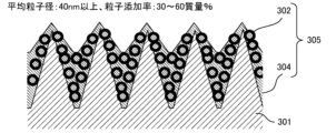
- FIG. 12B shows a case where the average particle diameter is 40 nm or more and the particle addition rate is 30 to 60 mass %, in which a hydrophilic film 305 containing silica particles 302 or alumina particles and a silica binder 304 is formed along the irregularities of the substrate 301.
- FIG. 12C shows a case where the average particle diameter is 10 to 20 nm and the particle addition rate exceeds 60 mass %, in which a hydrophilic film 305 containing silica particles 302 or alumina particles and a silica binder 304 is formed along the irregularities of the substrate 301.
- the hydrophilic film 305 is formed in such a way that it fills in the valleys of the unevenness of the substrate 301. This is thought to result in a decrease in Ra, a smaller actual surface area, and a decrease in hydrophilicity.
- the reason why the valleys are filled when the silica particles 302 or alumina particles are large is believed to be as follows.
- the particle diameter is small, the surface area of the particle per unit mass is large, so that the interaction between the particle surface and the surface of the substrate 301 is large, and the particles are aligned along the surface of the substrate 301 to form a film.
- the particles become larger, the surface area of the particles per unit mass becomes smaller, and the interaction with the surface of the substrate 301 becomes smaller. Therefore, the gravity of the particles becomes dominant, and the particles settle into the valleys of the substrate 301. As a result, it is considered that the film structure shown in FIG. 12B is formed.
- connection parts 205, 206 that connect the connection container 203 and the piping are screw-type connections as shown in Figures 5 to 7.
- the hydrophilic film coating liquid adheres to this screw-type part to form the hydrophilic film 305, there is a possibility that the system water 106 will leak from the connection parts 205, 206 when high pressure is applied to the pressure sensor unit 112 after the film is formed. This is thought to occur when the system water 106 moves through the gap 303 formed in the hydrophilic film 305 by capillary action.
- This concern can be resolved by screwing pipes or plastic screws 207 (see FIG. 13A) into the connection parts 205, 206 beforehand when applying the hydrophilic film coating liquid, so that the hydrophilic film coating liquid does not adhere to the screwed parts when applying the hydrophilic film coating liquid.
- this can be resolved by preventing the hydrophilic film 305 from being formed on the surfaces of the inlet/outlet 205a, 206a that contact the flow path 104 (more specifically, the surfaces of the connection parts 205, 206 that contact the flow path 104).
- connection container 203 When heat-curing, the connection container 203 needs to be heated below its heat-resistant temperature so that the material does not deform when heated. If the material is acrylic, there is a risk of deformation at temperatures above 70°C, so it is heated to 60°C with a margin. If the material is polycarbonate, there is a risk of deformation at temperatures above 120°C, so it is heated to 100°C with a margin.
- heating temperature the faster the heat curing process will proceed, so the higher the heat resistance of the substrate 301, the shorter the time required for heat curing.
- heating at 60°C for one hour will produce a hydrophilic film 305 with a pencil hardness of about B. If the film is then left in a high humidity environment with a relative humidity of about 70-90% for one hour and then heated at 60°C for one hour again, a hydrophilic film 305 with a pencil hardness of about HB will be obtained.
- a hydrophilic film 305 with a pencil hardness of about H will be obtained. Since the pencil hardness of the acrylic of the substrate 301 is about H, if the hydrophilic film 305 is cured to this extent, it will have the same hardness as the substrate 301, and is deemed to be at a level that is acceptable for practical use.
- the reason for including the step of leaving it in a high humidity environment is as follows. Because the thermal curing reaction of the coating liquid for the hydrophilic film is a hydrolysis reaction, it is effective to supply moisture during the reaction, but since the amount of moisture in the air is extremely small in a 60°C thermostatic chamber, moisture cannot be supplied from the air. Therefore, by interrupting the thermal curing midway and leaving it in a high humidity environment, the moisture in the air adheres to and is absorbed by the hydrophilic film 305 in the middle of thermal curing, and the thermal curing reaction can proceed efficiently when it is heated again.
- the film-forming method for the pressure sensor unit 112 can form a hydrophilic film 305 containing or consisting of at least one of silica particles 302 and alumina particles and a silicon compound on the inner surface 203a of the pressure sensor unit 112.
- the relationship between the arithmetic mean roughness Ra0 of the substrate 301 of the inner surface 203a and the arithmetic mean roughness Ra1 of the inner surface 203a after the hydrophilic film 305 is formed is 0.8 ⁇ Ra0 ⁇ Ra1. Therefore, the pressure sensor unit 112 obtained by this film-forming method can aspirate and discharge liquid without leaving any air bubbles inside.
- the automatic analysis method according to this embodiment is to aspirate and discharge liquid by nozzles (dispensing nozzles 102, 115, sample dispensing nozzle 10, reagent dispensing nozzle 11) connected to the dispensing mechanisms 100, 114 equipped with the pressure sensor unit 112.
- the pressure sensor unit 112 used in the automatic analysis method according to this embodiment has a hydrophilic film 305 formed on the inner surface 203a, the hydrophilic film 305 including or consisting of at least one of silica particles 302 and alumina particles and a silicon compound.
- the relationship between the arithmetic mean roughness Ra0 of the base material 301 of the inner surface 203a and the arithmetic mean roughness Ra1 of the inner surface 203a after the hydrophilic film 305 is formed is 0.8 ⁇ Ra0 ⁇ Ra1.
- the automatic analysis method uses the pressure sensor unit 112, and therefore can aspirate and discharge liquid without leaving any air bubbles inside.
- Dispersion A (1.0 g), silica sol solution B (7.5 g), and ethanol (21.5 g) were added to a polypropylene bottle having a capacity of 1000 ml, and the bottle was sealed and then stirred several times to prepare a coating solution (coating solution CS1 for hydrophilic film) (30 g) that forms a hydrophilic film 305 having a solid content of 1.0 mass % and in which silica particles account for 50 mass % of the solid content.
- the hydrophilic film 305 formed on an acrylic plate having an Ra of 10 nm using the hydrophilic film coating solution CS1 prepared in this example had a contact angle of 10° with water.
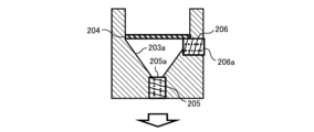
- FIGS. 13A to 13C are explanatory diagrams for explaining the process of forming a hydrophilic film on the inner surface of a connection container.
- Fig. 13A shows the state before coating.
- Fig. 13B shows the state after coating and thermal curing with an O-ring 204 attached.
- Fig. 13C shows the state after the pressure sensor 202 is provided, that is, the state of the pressure sensor unit 112.
- connection container 203 of the pressure sensor unit 112 used in this embodiment was placed on a flat table with the apex of the cone facing down.
- the Ra of the inner surface 203a of this connection container 203 is 100 nm.
- Resin screws 207 that fit the connection parts 205, 206 of the connection container 203 were screwed in beforehand to prevent the hydrophilic film coating liquid CS1 from adhering to the connection parts 205, 206. In this state, the hydrophilic film coating liquid CS1 was applied to the inner surface 203a of the connection container 203 using a dropper or the like.
- connection container 203 was turned upside down and placed on a sheet of paper that absorbed excess hydrophilic film coating solution CS1 with the apex of the cone facing up. After about 10 minutes, the connection container 203 was placed in a thermostatic chamber adjusted to 60°C and left there for 1 hour. The connection container 203 was then placed in a thermostatic chamber controlled to a temperature of 25°C and a humidity of 80% and left there for 1 hour. The connection container 203 was again placed in a thermostatic chamber adjusted to 60°C and left there for 1 hour.
- connection container 203 was then placed in a thermostatic chamber controlled to a temperature of 25°C and a humidity of 80% and left there for 1 hour, and finally placed in a thermostatic chamber adjusted to 60°C again and left there for 1 hour, forming the desired hydrophilic film 305 on the inner surface 203a of the connection container 203.
- the resin screws 207 were removed from the connection parts 205 and 206, and an O-ring 204 was attached along the periphery of the conical bottom surface of the connection container 203.
- the pressure sensor 202 was set so that the diaphragm 201 faced the inner surface 203a of the connecting container 203, thereby completing the pressure sensor unit 112.
- the O-ring 204 used above serves to close the gap between the inner surface 203a of the connecting container 203 and the pressure sensor 202, preventing leakage of the high-pressure system water 106. Therefore, although there is a very small amount of contact with the system water 106, there is a possibility that air bubbles will adhere to the O-ring 204 even if the hydrophilic film 305 is formed on the inner surface 203a of the connecting container 203. For this reason, it is desirable to form the hydrophilic film 305 on the surface of the O-ring 204 as well.
- the hydrophilic film coating solution CS1 was placed in a petri dish in an amount sufficient to completely immerse the O-ring 204, and the O-ring 204 was immersed in it for 10 seconds.
- the O-ring 204 was then picked up with tweezers, and similarly to the connection container 203, heated at 60° C. for 1 hour, and then left in an environment with a temperature of 25° C. and a humidity of 80% for 1 hour, a process of which was repeated twice, and then heated at 60° C. for 1 hour, to produce an O-ring 204 having a hydrophilic film 305 formed on its surface.
- the O-ring 204 is then attached to the connecting container 203 having the hydrophilic film 305 formed on the inner surface 203a, and thereafter the pressure sensor 202 is attached to complete the pressure sensor unit 112 of this embodiment.
- the pressure sensor unit 112 which does not have a hydrophilic film 305, was used to perform reagent and sample dispensing operations.
- the pressure sensor unit 112 which does not have a hydrophilic film 305, was used to perform reagent and sample dispensing operations.
- several air bubbles were found in the connecting container 203 of the pressure sensor unit 112, and air bubbles were also found adhering to the O-ring 204.
- the dispensing error exceeded the standard.
- FIG. 14 is an explanatory diagram showing the cut portions when measuring the surface roughness of the inner surface of the connection container.
- the Ra of the surface corresponding to the inner surface 203a of these connecting containers 203 was measured, it was 90 to 95 nm at the roughness measurement portion 210 of the vertical surface, and 86 to 91 nm at the roughness measurement portion 211 of the inclined surface. In other words, it was confirmed that the Ra after the formation of the hydrophilic film 305 was 0.8 times or more the Ra (100 nm) before the formation of the hydrophilic film 305.
- the thickness of the hydrophilic film 305 formed on the connecting container 203 was measured from the images obtained by observing and photographing the cut surface with a SEM. As a result, the thickness was 120 to 150 nm at the roughness measurement portion 210 of the vertical surface, and 170 to 200 nm at the roughness measurement portion 211 of the inclined surface.
- the amount of 15% by mass silica particle dispersion A prepared in Example 1 was changed from 1.0 g to 0.6 g, the amount of silica sol solution B was changed from 7.5 g to 10.5 g, and the amount of ethanol was changed from 21.5 g to 18.9 g, added to a 1000 ml polypropylene bottle, sealed the bottle, and stirred several times to prepare a coating solution (coating solution CS2 for hydrophilic film) (30 g) that forms a hydrophilic film 305 with a solid content of 1.0% by mass and in which silica particles make up 30% by mass of the solid content.
- a coating solution coating solution CS2 for hydrophilic film
- the thickness of the hydrophilic film 305 formed on the connecting container 203 was measured in the same manner as in Example 1, it was 100 to 120 nm at the roughness measurement portion 210 on the vertical surface, and 130 to 150 nm at the roughness measurement portion 211 on the inclined surface.
- the amount of 15% by mass silica particle dispersion A prepared in Example 1 was changed from 1.0 g to 1.2 g, the amount of silica sol solution B was changed from 7.5 g to 6.0 g, and the amount of ethanol was changed from 21.5 g to 22.8 g, added to a 1000 ml polypropylene bottle, sealed the bottle, and stirred several times to prepare a coating solution (coating solution CS3 for hydrophilic film) (30 g) that forms a hydrophilic film 305 with a solid content of 1.0% by mass and in which silica particles account for 60% by mass of the solid content.
- a coating solution coating solution CS3 for hydrophilic film
- a pressure sensor unit 112 was fabricated using the same process as in Example 1, except that the hydrophilic film coating solution CS3 was used instead of the hydrophilic film coating solution CS1. The unit was then set in the automatic analyzer 1 and the reagent and sample dispensing operations were carried out. As a result, no air bubbles were visually observed in the connection container 203 of the pressure sensor unit 112, and the dispensing error was within the standard.
- the pressure sensor unit 112 produced above was disassembled to retrieve the connecting container 203, and a vertical surface roughness measurement site 210 and an inclined surface roughness measurement site 211 were prepared in the same manner as in Example 1 to determine the Ra of the inner surface 203a.
- the Ra of the surface corresponding to the inner surface 203a of these connecting containers 203 was measured, it was 90 to 92 nm at the roughness measurement portion 210 of the vertical surface, and 82 to 88 nm at the roughness measurement portion 211 of the inclined surface.
- the Ra after the formation of the hydrophilic film 305 was 0.8 times or more the Ra (100 nm) before the formation of the hydrophilic film 305.
- the thickness of the hydrophilic film 305 formed on the connecting container 203 was measured in the same manner as in Example 1, it was 140 to 180 nm at the roughness measurement portion 210 on the vertical surface, and 200 to 230 nm at the roughness measurement portion 211 on the inclined surface.
- a pressure sensor unit 112 was fabricated using the same process as in Example 1, except that the silica particles (15 g) with an average particle size of 10 nm were replaced with silica particles (15 g) with an average particle size of 20 nm. The unit was then set in the automatic analyzer 1 and the operations of dispensing reagents and samples were carried out. As a result, no air bubbles were visually observed in the connected container 203 of the pressure sensor unit 112, and the dispensing error was within the standard.
- the pressure sensor unit 112 produced above was disassembled to retrieve the connecting container 203, and a vertical surface roughness measurement site 210 and an inclined surface roughness measurement site 211 were prepared in the same manner as in Example 1 to determine the Ra of the inner surface 203a.
- the Ra of the surface corresponding to the inner surface 203a of these connecting containers 203 was measured, it was 86 to 90 nm at the roughness measurement portion 210 of the vertical surface, and 82 to 84 nm at the roughness measurement portion 211 of the inclined surface.
- the Ra after the formation of the hydrophilic film 305 was 0.8 times or more the Ra (100 nm) before the formation of the hydrophilic film 305.
- a pressure sensor unit 112 was fabricated using the same process as in Example 1, except that the silica particles (15 g) with an average particle size of 10 nm were replaced with alumina particles (15 g) with an average particle size of 20 nm. The unit was then set in the automatic analyzer 1 and the operations of dispensing reagents and samples were carried out. As a result, no air bubbles were visually observed in the connected container 203 of the pressure sensor unit 112, and the dispensing error was within the standard.
- the pressure sensor unit 112 produced above was disassembled to retrieve the connecting container 203, and a vertical surface roughness measurement site 210 and an inclined surface roughness measurement site 211 were prepared in the same manner as in Example 1 to determine the Ra of the inner surface 203a.
- the Ra of the surface corresponding to the inner surface 203a of these connecting containers 203 was measured, it was 86 to 90 nm at the roughness measurement portion 210 of the vertical surface, and 82 to 84 nm at the roughness measurement portion 211 of the inclined surface.
- the Ra after the formation of the hydrophilic film 305 was 0.8 times or more the Ra (100 nm) before the formation of the hydrophilic film 305.
- the thickness of the hydrophilic film 305 formed on the connecting container 203 was measured in the same manner as in Example 1, it was 160 to 200 nm at the roughness measurement portion 210 on the vertical surface, and 200 to 240 nm at the roughness measurement portion 211 on the inclined surface.
- a pressure sensor unit 112 was fabricated in the same process as in Example 1, except that silica particles (15 g) with an average particle size of 10 nm were replaced with silica particles (15 g) with an average particle size of 40 nm, and the unit was set in the automatic analyzer 1 to perform the operations of dispensing reagents and dispensing samples.
- the dispensing error was 1/100 to 5/100 in terms of the mass ratio of the dispensed amount in both cases of dispensing reagents and dispensing samples.
- the dispensing error was slightly increased because the hydrophilicity of the hydrophilic film 305 was reduced due to the large particle size used, the dispensing error was within the standard range. In addition, no air bubbles were visually confirmed in the connecting container 203 of the pressure sensor unit 112.
- the pressure sensor unit 112 produced above was disassembled to retrieve the connecting container 203, and a vertical surface roughness measurement site 210 and an inclined surface roughness measurement site 211 were prepared in the same manner as in Example 1 to determine the Ra of the inner surface 203a.
- the Ra of the surface corresponding to the inner surface 203a of these connecting containers 203 was measured, it was 84 to 86 nm at the roughness measurement portion 210 of the vertical surface, and 80 to 82 nm at the roughness measurement portion 211 of the inclined surface.
- the Ra after the formation of the hydrophilic film 305 was 0.8 times or more the Ra (100 nm) before the formation of the hydrophilic film 305.
- the thickness of the hydrophilic film 305 formed on the connecting container 203 was measured in the same manner as in Example 1, it was 180 to 220 nm at the roughness measurement portion 210 on the vertical surface, and 250 to 300 nm at the roughness measurement portion 211 on the inclined surface.
- the amount of 15% by mass silica particle dispersion A prepared in Example 1 was changed from 1.0 g to 1.3 g, the amount of silica sol solution B was changed from 7.5 g to 5.25 g, and the amount of ethanol was changed from 21.5 g to 23.45 g, added to a 1000 ml polypropylene bottle, sealed the bottle, and stirred several times to prepare a coating solution (coating solution CS4 for hydrophilic film) (30 g) that forms a hydrophilic film with a solid content of 1.0% by mass and in which silica particles account for 65% by mass of the solid content.
- a coating solution coating solution CS4 for hydrophilic film
- the pressure sensor unit 112 produced above was disassembled to retrieve the connecting container 203, and a vertical surface roughness measurement site 210 and an inclined surface roughness measurement site 211 were prepared in the same manner as in Example 1 to determine the Ra of the inner surface 203a.
- the Ra of the surface corresponding to the inner surface 203a of these connecting containers 203 was measured, it was 88 to 90 nm at the roughness measurement portion 210 of the vertical surface, and 80 to 84 nm at the roughness measurement portion 211 of the inclined surface.
- the Ra after the formation of the hydrophilic film 305 was 0.8 times or more the Ra (100 nm) before the formation of the hydrophilic film 305.
- the thickness of the hydrophilic film 305 formed on the connecting container 203 was measured in the same manner as in Example 1, it was 160 to 200 nm at the roughness measurement portion 210 on the vertical surface and 220 to 250 nm at the roughness measurement portion 211 on the inclined surface.
- the amount of 15% by mass silica particle dispersion A prepared in Example 1 was changed from 1.0 g to 0.5 g, the amount of silica sol solution B was changed from 7.5 g to 11.25 g, and the amount of ethanol was changed from 21.5 g to 18.25 g, added to a 1000 ml polypropylene bottle, sealed the bottle, and stirred several times to prepare a coating solution (coating solution CS5 for hydrophilic film) (30 g) that forms a hydrophilic film 305 with a solid content of 1.0% by mass and silica particles making up 25% by mass of the solid content.
- a coating solution coating solution CS5 for hydrophilic film
- the pressure sensor unit 112 produced above was disassembled to retrieve the connecting container 203, and a vertical surface roughness measurement site 210 and an inclined surface roughness measurement site 211 were prepared in the same manner as in Example 1 to determine the Ra of the inner surface 203a.
- the Ra of the surface corresponding to the inner surface 203a of these connecting containers 203 was measured, it was 92 to 97 nm at the roughness measurement portion 210 of the vertical surface, and 88 to 93 nm at the roughness measurement portion 211 of the inclined surface.
- the Ra after the formation of the hydrophilic film 305 was 0.8 times or more the Ra (100 nm) before the formation of the hydrophilic film 305.
- the thickness of the hydrophilic film 305 formed on the connecting container 203 was measured in the same manner as in Example 1, it was 100 to 120 nm at the roughness measurement portion 210 on the vertical surface, and 140 to 170 nm at the roughness measurement portion 211 on the inclined surface.
- the present invention is not limited to the above-mentioned embodiments and examples, and various modified examples are included.
- the above-mentioned embodiments have been described in detail to explain the present invention in an easy-to-understand manner, and are not necessarily limited to those having all of the configurations described. It is also possible to replace part of the configuration of one embodiment with the configuration of another embodiment, and it is also possible to add the configuration of another embodiment to the configuration of one embodiment. It is also possible to add, delete, or replace part of the configuration of each embodiment with other configurations.
Landscapes
- Physics & Mathematics (AREA)
- Health & Medical Sciences (AREA)
- Life Sciences & Earth Sciences (AREA)
- Chemical & Material Sciences (AREA)
- Analytical Chemistry (AREA)
- Biochemistry (AREA)
- General Health & Medical Sciences (AREA)
- General Physics & Mathematics (AREA)
- Immunology (AREA)
- Pathology (AREA)
- Automatic Analysis And Handling Materials Therefor (AREA)
Abstract
Description
この構造を採ることにより、圧力センサユニット内部の気泡はある程度除去される。
前述した以外の課題、構成および効果は以下の実施形態の説明により明らかにされる。
図1は、本発明の一実施形態に係る自動分析装置の全体構成の一例を示した説明図である。図2は、本発明の一実施形態に係る自動分析装置の全体構成の他の一例を示した説明図である。
また、蓋19の一部には、試薬吸引用の貫通孔である試薬吸引孔20が設けられている。なお、試薬分注ノズル11は回転と上下動が可能であり、試薬保冷庫4の蓋19に設けられた試薬吸引孔20の上方に回転移動した後に下降し、試薬吸引孔20を通過する。その後、試薬分注ノズル11は、試薬吸引孔20を通った試薬分注ノズル11の先端を所定の試薬容器2内の試薬に入れ、所定量の試薬を吸引する。その後、試薬分注ノズル11は上昇および回転してインキュベーターディスク9の所定位置の上方に移動し、インキュベーターディスク9に設置された反応容器8内に試薬を吐出する。
なお、以上の各種構成部材の駆動および駆動タイミングについては、図1には図示されていない自動分析装置1のパソコンなどの制御ユニット103(図3、図4参照)によって制御されている。
まず、この自動分析装置22は、サンプル分注ノズル23と試薬分注ノズル24の先にチップが付いていないタイプである。自動分析装置22は、これらのノズルでのサンプルおよび試薬の吸引、排出を終えた後、チップを交換しない代わりに、ノズルの先端を洗浄するためのノズル洗浄機構25に先端を入れて洗浄する。
また、この自動分析装置22では反応容器8内の試薬・サンプル混合物の発色強度、濁度などを測定ユニット26で定量する。
図3は、本発明の一実施形態に係る自動分析装置における分注機構の一例を示す概略模式図である。図4は、本発明の一実施形態に係る自動分析装置における分注機構の他の一例を示す概略模式図である。
まず、この分注機構114は、分注ノズル115の先にチップが付いていないタイプである。分注ノズル115は、サンプルや試薬の吸引および吐出を終えた後、チップを交換しない代わりに、ノズルの先端を洗浄するための洗浄水116の入ったノズル洗浄機構117にノズルの先端を入れて洗浄する。
前述した圧力センサユニット112について詳述する。
図5は、本発明の一実施形態に係る自動分析装置における圧力センサユニットの一例を示す断面模式図である。図6は、本発明の一実施形態に係る自動分析装置における圧力センサユニットの他の一例を示す断面模式図である。図7は、本発明の一実施形態に係る自動分析装置における圧力センサユニットのさらなる他の一例を示す断面模式図である。
圧力センサユニット112は、例えば、図6に示すように、接続容器203の内部を円錐と円筒とを繋げた構造とすることができる。この場合、流入出口206aは円錐の部分ではなく、円筒の部分に形成するとよい。円錐部分より円筒部分の方が、流入出口206a形成の加工がしやすいメリットがある。
また、圧力センサユニット112は、例えば、図7に示すように、接続容器203の内部を円筒状としつつ、上部の角部を丸めた構造とすることができる。このような丸みを帯びた構造とした場合も、上部の角部における気泡の滞留を抑制することができる。
a)親水膜用コート液の組成・形成方法の概略
本実施形態における親水膜305は、この膜を形成する親水膜用コート液を接続容器203内部に塗布した後、硬化させることにより製する。親水膜用コート液の材料組成は、具体的には親水性の材料として二酸化ケイ素(シリカ)製の粒子(シリカ粒子)および三酸化二アルミニウム(アルミナ)製の粒子(アルミナ粒子)のうちの少なくとも一方と、これらの粒子を保持するバインダと、これらを分散または溶解する有機溶剤とからなる。なお、バインダは、加熱すると主成分がシリカになるアルコキシシラン化合物であることが好ましい。
本実施形態においては、シリカ粒子やアルミナ粒子のサイズを規定することにより親水膜305の親水性がより向上し、より気泡レス化に寄与する。また、シリカ粒子やアルミナ粒子の添加率を規定することにより親水膜305の親水性がより向上し、より気泡レス化に寄与する。
図8に示すように、親水膜305は、基材301の上に形成されている。親水膜305は、シリカ粒子302とシリカバインダ304(図12A~図12C参照)とその間にある空隙303とを含んでなる。シリカバインダ304は、複数のシリカ粒子302の間および基材301に薄く付着して膜としての構造を保持している。シリカ自身の水との接触角は30°程度であるが、親水膜305表面のシリカ粒子302による細かな凹凸、および表面の空隙303により、水との接触角が低減する。さらに、シリカ粒子302間の隙間、および空隙303に対して毛細管現象により、結露水が染み込むことにより、親水膜305表面の水との接触角がさらに低減する。これにより、水との接触角が15°以下の親水膜305が形成可能となる。
なお、シリカ粒子302に代えてアルミナ粒子を用いた場合も同様の膜構造となり、同様の効果が得られる。
この親水膜用コート液は、シリカ粒子およびアルミナ粒子のうちの少なくとも一方と、シリカバインダの前駆体とを有機溶剤に分散および溶解することにより製する。有機溶剤は、アルコール系の溶剤である。これら3種類の材料について説明する。
親水性の材料として、本実施形態ではシリカ粒子およびアルミナ粒子のうちの少なくとも一方を用いる。これらの粒子の平均粒子径は、好ましくは10~50nm、より好ましくは10~20nmである。以下にこの理由を記す。
なお、これらの粒子の平均粒子径は、堀場製作所製粒度分析装置LA-950V2で測定することができる。
シリカ粒子およびアルミナ粒子の親水性は、粒子の表面により発揮される。例えば、シリカ粒子の場合は、ケイ素と酸素の結合の一部が切れて水酸基が露出し、これが親水性を発揮すると考えられている。また、アルミナの場合は、アルミニウムと酸素の結合の一部が切れて水酸基が露出し、これが親水性を発揮していると考えられている。そのため、単位質量当たりの粒子の表面積が大きいほど、単位質量当たりの表面に露出している水酸基の数が増えるので親水性が向上する。粒子径が小さい方が単位質量当たりの表面積が大きくなるため、親水性をより強く発揮する。
これらの粒子の密度は、シリカ粒子が2.5~2.6g/cm3、アルミナ粒子が3.9~4.1g/cm3であり、後述する溶剤の0.8~1.0g/cm3に比べてかなり大きい。そのため、これらの粒子の粒子径が大きいと親水膜用コート液中で沈降する。サイズ的にはシリカ粒子の場合は70nm以上、アルミナ粒子の場合は50nm以上で沈降が顕著に見られるようになる。そのため、粒子径が大きい場合は使用前に攪拌し、親水膜用コート液全体に分散させてから使用する必要がある。よって、上記理由から好ましい粒子の平均粒子径は50nm以下となる。
表面に凹凸のある基材301にコーティングした場合、粒子が谷の部分をある程度埋めるので表面凹凸が小さくなる。これは算術表面粗さ(Ra)が小さくなることで確認できる。Raが小さくなると、実表面積が小さくなるので、投影面積の単位面積当たりのシリカ粒子やアルミナ粒子由来の水酸基の数が減り、所望の親水性が得られない可能性がある。粒子が大きいほど、具体的には平均粒子径が30nm以上の粒子を用いた場合、谷を埋める傾向が強い。平均粒子径が10~20nmの場合は、谷を埋める効果はわずかであり、凹凸の形状に沿って、谷を埋めずにコーティングされるので、Raはほとんど変化がなく、高い親水性を付与することが可能である。この観点からは、上記理由により、より好ましい平均粒子径は10~20nmとなる。
粒子が小さすぎると、具体的には平均粒子径が10nm未満の場合、秤量や混合等の際、空気中に粉塵として広がる恐れがある。空気中に漂っているこれら粒子を人間が吸うと呼吸障害などが発生する恐れがある。したがって、用いるシリカ粒子およびアルミナ粒子の平均粒子径は10nm以上が好ましい。この観点からは、上記理由により、好ましい平均粒子径は10nm以上となる。
一実施形態に係る親水膜305は、製膜後の主成分がシリカのバインダである。シリカは有機溶剤には不溶であるが、その前駆体は有機溶剤に溶解するものがある。本実施形態では、有機溶剤に溶解するシリカの前駆体を用いる。
親水膜用コート液の溶剤は、通常の有機溶剤を用いる。但し、圧力センサユニット112の筐体である接続容器203は機械加工のし易さからアクリルやポリカーボネートといった樹脂が用いられることが多い。しかし、これらの樹脂は溶剤の種類によっては溶解したり、膨潤したりしてしまう恐れがある。そこで、これらの樹脂を溶解、膨潤させない、或いはほとんどさせないという点で、アルコール系の溶剤が好適である。具体的には、炭素数が1~4のメタノール、エタノール、1-プロパノール、2-プロパノール、1-ブタノール、2-ブタノール、tert-ブタノールなどが好適である。これらの溶剤は沸点が60~120℃程度であるため、コーティング後の揮発が敏速であり、製膜に要する時間を短くできるメリットがある。ブタノールより炭素数が多いと加水分解性のケイ素化合物を溶解しにくくなり、しかも塗布後の乾燥に時間がかかるので、炭素数が5以上のアルコールは好適ではない。
図9は、親水膜の膜厚(nm)と水との接触角(°)との関係を示したグラフである。
図9のグラフは、シリカ粒子302とシリカの前駆体との質量比率が1:1の親水膜用コート液で親水膜305を製膜した結果を示している。また、基材301は、算術表面粗さ(Ra)が10nmであり、目視では平坦なアクリル板である。図9に示すように、親水膜305の膜厚が40nm以上になると、水との接触角が15°以下まで低下し、十分な親水性を発揮する。さらに、親水膜305の膜厚が50nm以上になると水との接触角は10°まで低下し、より高い親水性を発揮する。シリカ粒子302に代えてアルミナ粒子を用いた場合もシリカ粒子302を使った場合とほぼ同様の結果であった。したがって、本実施形態における親水膜305の膜厚は50nm以上が好ましい。なお、膜厚は、複数の任意の箇所の膜厚を測定し、その平均値(平均膜厚)で管理することができる。
親水膜305を形成する親水膜用コート液中の固形分は、親水性の材料であるシリカ粒子302およびアルミナ粒子のうちの少なくとも一方と、バインダであるシリカの前駆体とである。この両者の比率が異なると親水膜305の性能、すなわち、水との接触角が変化する。シリカ粒子302とシリカの前駆体との比率を変えて膜厚がほぼ100nmになるよう製膜した親水膜305の水との接触角を調べた。結果を図10に示す。
図10の横軸はシリカ粒子302の割合を示している。シリカバインダ304の前駆体の割合は、100%からシリカ粒子302の割合を引いた値となる。なお、ここで用いたシリカ粒子302の平均粒子径は、20nmであった。シリカ粒子302の平均粒子径は、堀場製作所製粒度分析装置LA-950V2で測定した。接触角は、協和界面科学株式会社製接触角計(型式:CA-D)を用いて測定した。
一方、Raが100nmのアクリル板に親水膜305を製膜した(b)の場合は、Raが5nmの場合よりもさらに接触角は下がった。シリカ粒子302の含有率が30~60質量%では接触角が4~5°まで低下した。すなわち、Raが大きい基板に製膜した方が、親水性が向上した。
アルミナ粒子(平均粒子径20nm)でも同様の実験を行ったところ、シリカ粒子302と同様、粒子の含有率は30~60質量%が好適であることが判った。なお、アルミナ粒子の平均粒子径も堀場製作所製粒度分析装置LA-950V2で測定した。
図11は、親水膜中のSiO2粒子の割合(質量%)と水との接触角(°)との関係を示したグラフである。
一方、平均粒子径50nmのシリカ粒子302を30質量%含有する親水膜305のRaは55nmであった。平均粒子径50nmのシリカ粒子302を60質量%含有する親水膜305のRaは30nmであった。
図10の結果と同様、Raが小さくなったことが接触角を高める要因になっていることが判った。
以上の結果と原因を図12A~図12Cに模式的に示す。
図12Aは、平均粒子径が10~20nm、粒子添加率が30~60質量%の場合であり、シリカ粒子302またはアルミナ粒子とシリカバインダ304とを含んでなる親水膜305が、基材301の凹凸に沿って製膜されている。
一方、図12Bは、平均粒子径が40nm以上、粒子添加率が30~60質量%の場合であり、シリカ粒子302またはアルミナ粒子とシリカバインダ304とを含んでなる親水膜305が、基材301の凹凸に沿って製膜されている。
図12Cは、平均粒子径が10~20nm、粒子添加率が60質量%を超える場合であり、シリカ粒子302またはアルミナ粒子とシリカバインダ304とを含んでなる親水膜305が、基材301の凹凸に沿って製膜されている。
粒子径が小さい場合、単位質量当たりの粒子の表面積が大きいので粒子の表面と基材301表面の相互作用が大きく、基材301の表面に沿った形で粒子が並んで製膜される。
これに対し、粒子が大きくなると、単位質量当たりの粒子の表面積が小さくなるので、基材301表面の相互作用が小さくなる。そのため、粒子の重力が支配的になり、基材301の谷の部分に沈降する。その結果、図12Bのような膜構造になると考えられる。
圧力センサユニット112の製膜は、親水膜用コート液の塗布および熱硬化により完了する。
(i)塗布(ねじ込み工程、塗布工程)
親水膜用コート液をスポイトなどで接続容器203内に塗布する。このとき、接続容器203と配管(流路104)とを接続する接続部位205、206は、図5~7に示すように、ねじ込み式の接続になっている。しかし、このねじ込み部分に親水膜用コート液が付着して親水膜305が形成されると、製膜後、圧力センサユニット112に高圧がかかった場合に、接続部位205、206からシステム水106が漏れてくる可能性がある。これはシステム水106が親水膜305内に形成される空隙303内を毛細管現象によって移動して生じると考えられる。
親水膜用コート液を塗布後、熱硬化を行い、製膜する。なお、熱硬化前かつ配管または樹脂製のねじ207を外す前に、内面203aに付着した余分な親水膜用コート液を除去するとよい。これは、紙などの液体を吸収する能力のあるものを親水膜用コート液に接触させることで行うことができる。
本実施形態に係る自動分析方法は、前記圧力センサユニット112を備えた分注機構100、114に接続されたノズル(分注ノズル102、115、サンプル分注ノズル10、試薬分注ノズル11)により液体を吸引・吐出する、というものである。本実施形態に係る自動分析方法で用いる圧力センサユニット112は、前述したように、内面203aにシリカ粒子302およびアルミナ粒子のうちの少なくとも一方と、ケイ素化合物と、を含んでなる、または、からなる親水膜305が形成されている。そして、前記内面203aの基材301の算術平均粗さRa0と、前記親水膜305形成後の内面203aの算術平均粗さRa1との関係が、0.8×Ra0≦Ra1となっている。このように、自動分析方法は、前記圧力センサユニット112を用いているので、内部に気泡を残さずに、液体を吸引・吐出することができる。
平均粒子径が10nmのシリカ粒子(15g)、および分散剤としてジエチレングリコールモノアセテート(0.5g)、溶剤としてエタノール(84.5g)を内容量200mlのポリプロピレン製のビンに入れ、これらをオーバーヘッドスターラ―で攪拌することにより15質量%シリカ粒子の分散液Aを100g調製した。
加水分解後の固形分濃度が2質量%になるよう調製した溶剤がエタノールのシリカゾル溶液Bを750g調製した。
なお、本実施例で調製した親水膜用コート液CS1を用いてRaが10nmのアクリル板に製膜された親水膜305の水との接触角は10°であった。
図13A~図13Cを参照して、このプロセスについて説明する。
図13A~図13Cはいずれも、接続容器の内面への親水膜成膜プロセスを説明する説明図である。なお、図13Aはコーティング前の状態を示している。図13Bはコーティングおよび熱硬化後、O-リング204を装着した状態を示している。図13Cは圧力センサ202を設けた状態、つまり、圧力センサユニット112の状態を示している。
次に、図13Cに示すように、圧力センサ202をダイアフラム201が接続容器203の内面203aに向くようにセットして、圧力センサユニット112を完成させた。
上記で使ったO-リング204は、接続容器203の内面203aと圧力センサ202との隙間を塞ぎ、高圧のシステム水106が漏れないようにする役割がある。そのため、極僅かであるがシステム水106との接触がある。したがって、接続容器203の内面203aに親水膜305を形成しても、O-リング204上に気泡が付着する可能性がある。そのため、O-リング204表面も親水膜305を形成することが望ましい。
そして、前述したように、このO-リング204を内面203aに親水膜305を形成した接続容器203に装着し、その後、圧力センサ202を装着して本実施例の圧力センサユニット112を完成させた。
上記(1)~(3)のプロセスで製した圧力センサユニット112を図3に示す分注機構100に取り付け、これを図1の自動分析装置1にセットし、試薬分注およびサンプル分注の操作を行った。その結果、圧力センサユニット112の接続容器203内に目視では気泡は確認されず、分注の誤差も基準以下であった。
また、接続容器203に形成された親水膜305の厚さは切断面をSEMで観察・撮影し、得られた画像から測定した。その結果、垂直面の粗さ測定部位210では120~150nm、傾斜面の粗さ測定部位211では170~200nmであった。
これらの接続容器203の内面203aにあたる面のRaを測定したところ、垂直面の粗さ測定部位210では95~97nm、傾斜面の粗さ測定部位211では90~95nmであった。つまり、親水膜305形成後のRaは親水膜305形成前のRa(100nm)の0.8倍以上であることが確認された。
また、接続容器203に形成された親水膜305の厚さを実施例1と同様に測定すると、垂直面の粗さ測定部位210では100~120nm、傾斜面の粗さ測定部位211では130~150nmであった。
これらの接続容器203の内面203aにあたる面のRaを測定したところ、垂直面の粗さ測定部位210では90~92nm、傾斜面の粗さ測定部位211では82~88nmであった。つまり、親水膜305形成後のRaは親水膜305形成前のRa(100nm)の0.8倍以上であることが確認された。
また、接続容器203に形成された親水膜305の厚さを実施例1と同様に測定すると、垂直面の粗さ測定部位210では140~180nm、傾斜面の粗さ測定部位211では200~230nmであった。
これらの接続容器203の内面203aにあたる面のRaを測定したところ、垂直面の粗さ測定部位210では86~90nm、傾斜面の粗さ測定部位211では82~84nmであった。つまり、親水膜305形成後のRaは親水膜305形成前のRa(100nm)の0.8倍以上であることが確認された。
また、接続容器203に形成された親水膜305の厚さを実施例1と同様に測定すると、垂直面の粗さ測定部位210では160~200nm、傾斜面の粗さ測定部位211では200~240nmであった。
これらの接続容器203の内面203aにあたる面のRaを測定したところ、垂直面の粗さ測定部位210では86~90nm、傾斜面の粗さ測定部位211では82~84nmであった。つまり、親水膜305形成後のRaは親水膜305形成前のRa(100nm)の0.8倍以上であることが確認された。
また、接続容器203に形成された親水膜305の厚さを実施例1と同様に測定すると、垂直面の粗さ測定部位210では160~200nm、傾斜面の粗さ測定部位211では200~240nmであった。
用いる粒子径が大きいため親水膜305の親水性が低くなり分注の誤差が若干大きくなったものの、分注の誤差は基準以下であった。また、圧力センサユニット112の接続容器203内に気泡は目視では確認されなかった。
これらの接続容器203の内面203aにあたる面のRaを測定したところ、垂直面の粗さ測定部位210では84~86nm、傾斜面の粗さ測定部位211では80~82nmであった。つまり、親水膜305形成後のRaは親水膜305形成前のRa(100nm)の0.8倍以上であることが確認された。
また、接続容器203に形成された親水膜305の厚さを実施例1と同様に測定すると、垂直面の粗さ測定部位210では180~220nm、傾斜面の粗さ測定部位211では250~300nmであった。
用いる粒子の添加率が高いため親水膜305の親水性が低くなり分注の誤差が若干大きくなったものの、分注の誤差は基準以下であった。
これらの接続容器203の内面203aにあたる面のRaを測定したところ、垂直面の粗さ測定部位210では88~90nm、傾斜面の粗さ測定部位211では80~84nmであった。つまり、親水膜305形成後のRaは親水膜305形成前のRa(100nm)の0.8倍以上であることが確認された。
また、接続容器203に形成された親水膜305の厚さを実施例1と同様に測定すると、垂直面の粗さ測定部位210では160~200nm、傾斜面の粗さ測定部位211では220~250nmであった。
用いる粒子の添加率が低いため親水膜305の親水性が低くなり分注の誤差が若干大きくなったものの、分注の誤差は基準以下であった。また、圧力センサユニット112の接続容器203内に気泡は目視では確認されなかった。
これらの接続容器203の内面203aにあたる面のRaを測定したところ、垂直面の粗さ測定部位210では92~97nm、傾斜面の粗さ測定部位211では88~93nmであった。つまり、親水膜305形成後のRaは親水膜305形成前のRa(100nm)の0.8倍以上であることが確認された。
また、接続容器203に形成された親水膜305の厚さを実施例1と同様に測定すると、垂直面の粗さ測定部位210では100~120nm、傾斜面の粗さ測定部位211では140~170nmであった。
2 試薬容器
3 試薬容器装てん部
4 試薬保冷庫
5 サンプル容器
6 ラック
7 ラック搬送ライン
8 反応容器
9 インキュベーターディスク
10 サンプル分注ノズル
11 試薬分注ノズル
12 反応容器搬送機構
13 サンプル分注位置
14 サンプル分注チップ/反応容器搬送機構
15 サンプル分注チップ/反応容器保持部材
16 反応容器攪拌機構
17 サンプル分注チップ/反応容器廃棄孔
18 サンプル分注チップ装着位置
19 蓋
20 試薬吸引孔
21 検出ユニット
22 自動分析装置
23 サンプル分注ノズル
24 試薬分注ノズル
25 ノズル洗浄機構
26 測定ユニット
100 分注機構
101 チップ
102 分注ノズル
103 制御ユニット
104 流路
105 シリンジ
106 システム水
107 シリンダ
108 プランジャ
109 給水タンク
110 電磁弁
111 給水ポンプ
112 圧力センサユニット
113 圧力センサ
114 分注機構
115 分注ノズル
116 洗浄水
117 ノズル洗浄機構
118 流路
201 ダイアフラム
202 圧力センサ
203 接続容器
203a 内面
204 O-リング
205 接続部位
205a 流入出口
206 接続部位
206a 流入出口
208 垂直面切断箇所
209 傾斜面切断箇所
210 垂直面の粗さ測定部位
211 傾斜面の粗さ測定部位
301 基材
302 シリカ粒子
303 空隙
304 シリカバインダ
305 親水膜
Claims (11)
- 液体を吸引・吐出するノズルと、該ノズルに接続され液体を吸引・吐出させるための圧力を発生させる圧力発生手段と、前記ノズルおよび前記圧力発生手段を含めた流路内の圧力を測定する圧力センサユニットと、を備えた分注機構を有し、
前記圧力センサユニットの内面に、シリカ粒子およびアルミナ粒子のうちの少なくとも一方と、ケイ素化合物と、を含んでなる親水膜が形成されており、
前記内面の基材の算術平均粗さRa0と、前記親水膜形成後の内面の算術平均粗さRa1との関係が、0.8×Ra0≦Ra1であること、
を特徴とする自動分析装置。 - 前記圧力センサユニットの液体の流入出口の1つあたりの断面積をα、前記圧力センサユニットの受圧面の面積をβとしたとき、α<βであること、
を特徴とする請求項1に記載の自動分析装置。 - 前記圧力センサユニットの内面形状が円錐であり、
前記円錐の頂点部が鉛直上方となるよう配置され、
前記円錐の底周面の接線方向に前記圧力発生手段と接続される液体の流入出口が設けられ、
前記頂点部に前記ノズルと接続される液体の流入出口が設けられ、
前記円錐の底面に前記圧力センサユニットの受圧面が配置されていること、
を特徴とする請求項1に記載の自動分析装置。 - 前記シリカ粒子および前記アルミナ粒子の平均粒子径が10~20nmであること、
を特徴とする請求項1に記載の自動分析装置。 - 前記シリカ粒子および前記アルミナ粒子の割合が30~60質量%であること、
を特徴とする請求項1に記載の自動分析装置。 - 前記圧力センサユニットの圧力センサと前記圧力センサユニットの筐体である接続容器との間にO-リングが装着されており、前記O-リングの表面に前記親水膜が形成されていること、
を特徴とする請求項1に記載の自動分析装置。 - 前記流入出口における前記流路と接する面には前記親水膜が形成されていないこと、
を特徴とする請求項3に記載の自動分析装置。 - 前記親水膜の膜厚が50nm以上であること、
を特徴とする請求項1に記載の自動分析装置。 - 前記親水膜の算術平均粗さが0.08μm以上であること、
を特徴とする請求項1に記載の自動分析装置。 - 内面にシリカ粒子およびアルミナ粒子のうちの少なくとも一方と、ケイ素化合物と、を含んでなる親水膜が形成されており、前記内面の基材の算術平均粗さRa0と、前記親水膜形成後の内面の算術平均粗さRa1との関係が、0.8×Ra0≦Ra1である圧力センサユニットを備えた分注機構に接続されたノズルにより液体を吸引・吐出すること、
を特徴とする自動分析方法。 - 圧力センサユニットのすべての流入出口にねじ部材をねじ込むねじ込み工程と、
前記流入出口に前記ねじ部材をねじ込んだ圧力センサユニットの内面に、シリカ粒子およびアルミナ粒子のうちの少なくとも一方と、ケイ素化合物と、を含む親水膜用コート液を塗布する塗布工程と、
加熱して、前記内面に塗布した親水膜用コート液を親水膜にする製膜工程と、
を有し、
前記内面の基材の算術平均粗さRa0と、前記親水膜形成後の内面の算術平均粗さRa1との関係が、0.8×Ra0≦Ra1であること、を特徴とする圧力センサユニットの製膜方法。
Priority Applications (3)
| Application Number | Priority Date | Filing Date | Title |
|---|---|---|---|
| JP2025526066A JPWO2024252990A1 (ja) | 2023-06-09 | 2024-05-28 | |
| CN202480010547.1A CN120641762A (zh) | 2023-06-09 | 2024-05-28 | 自动分析装置、自动分析方法及压力传感器单元的制膜方法 |
| EP24819221.3A EP4726399A1 (en) | 2023-06-09 | 2024-05-28 | Automatic analyzer, automatic analysis method, and film-forming method for pressure sensor unit |
Applications Claiming Priority (2)
| Application Number | Priority Date | Filing Date | Title |
|---|---|---|---|
| JP2023-095885 | 2023-06-09 | ||
| JP2023095885 | 2023-06-09 |
Publications (1)
| Publication Number | Publication Date |
|---|---|
| WO2024252990A1 true WO2024252990A1 (ja) | 2024-12-12 |
Family
ID=93795990
Family Applications (1)
| Application Number | Title | Priority Date | Filing Date |
|---|---|---|---|
| PCT/JP2024/019593 Ceased WO2024252990A1 (ja) | 2023-06-09 | 2024-05-28 | 自動分析装置、自動分析方法および圧力センサユニットの製膜方法 |
Country Status (4)
| Country | Link |
|---|---|
| EP (1) | EP4726399A1 (ja) |
| JP (1) | JPWO2024252990A1 (ja) |
| CN (1) | CN120641762A (ja) |
| WO (1) | WO2024252990A1 (ja) |
Citations (6)
| Publication number | Priority date | Publication date | Assignee | Title |
|---|---|---|---|---|
| JP2005274471A (ja) | 2004-03-26 | 2005-10-06 | Hitachi High-Technologies Corp | 分注装置及びそれを備えた自動分析装置 |
| JP2007242759A (ja) * | 2006-03-07 | 2007-09-20 | Sumitomo Chemical Co Ltd | 太陽電池カバー |
| US20160003860A1 (en) * | 2013-02-15 | 2016-01-07 | Siemens Healthcare Diagnostics Inc. | Real-time volume confirmation dispensing apparatus and methods |
| JP6156233B2 (ja) * | 2014-04-01 | 2017-07-05 | 株式会社デンソー | 圧力センサ |
| WO2017170748A1 (ja) * | 2016-03-31 | 2017-10-05 | 京セラ株式会社 | 応力センサ |
| JP2022035590A (ja) * | 2020-08-21 | 2022-03-04 | 株式会社日立ハイテク | 分注装置 |
-
2024
- 2024-05-28 EP EP24819221.3A patent/EP4726399A1/en active Pending
- 2024-05-28 JP JP2025526066A patent/JPWO2024252990A1/ja active Pending
- 2024-05-28 CN CN202480010547.1A patent/CN120641762A/zh active Pending
- 2024-05-28 WO PCT/JP2024/019593 patent/WO2024252990A1/ja not_active Ceased
Patent Citations (6)
| Publication number | Priority date | Publication date | Assignee | Title |
|---|---|---|---|---|
| JP2005274471A (ja) | 2004-03-26 | 2005-10-06 | Hitachi High-Technologies Corp | 分注装置及びそれを備えた自動分析装置 |
| JP2007242759A (ja) * | 2006-03-07 | 2007-09-20 | Sumitomo Chemical Co Ltd | 太陽電池カバー |
| US20160003860A1 (en) * | 2013-02-15 | 2016-01-07 | Siemens Healthcare Diagnostics Inc. | Real-time volume confirmation dispensing apparatus and methods |
| JP6156233B2 (ja) * | 2014-04-01 | 2017-07-05 | 株式会社デンソー | 圧力センサ |
| WO2017170748A1 (ja) * | 2016-03-31 | 2017-10-05 | 京セラ株式会社 | 応力センサ |
| JP2022035590A (ja) * | 2020-08-21 | 2022-03-04 | 株式会社日立ハイテク | 分注装置 |
Non-Patent Citations (1)
| Title |
|---|
| See also references of EP4726399A1 |
Also Published As
| Publication number | Publication date |
|---|---|
| JPWO2024252990A1 (ja) | 2024-12-12 |
| CN120641762A (zh) | 2025-09-12 |
| EP4726399A1 (en) | 2026-04-15 |
Similar Documents
| Publication | Publication Date | Title |
|---|---|---|
| CN101490562B (zh) | 液体输送设备 | |
| Iqbal et al. | Understanding of the role of dilution on evaporative deposition patterns of blood droplets over hydrophilic and hydrophobic substrates | |
| CN105073587B (zh) | 弯月面降低构件 | |
| JPH01257261A (ja) | 組織などの処理方法と装置 | |
| GB2130553A (en) | Integral reagent despenser | |
| JP2003262189A (ja) | 可変速度ポンプ駆動型計量システムのための流体計量配分アルゴリズム | |
| JP2019516073A (ja) | 親水性コーティングを備えたマイクロチャネルを有するマイクロ流体デバイス | |
| TW200534331A (en) | Non-porous adherent inert coatings and methods of making | |
| JP6886023B2 (ja) | 試料処理システムおよび方法 | |
| CN101790688A (zh) | 分注管嘴和自动分析装置 | |
| CN111272791A (zh) | 一种用于全反射x射线荧光分析的旋涂制样方法 | |
| EP4726399A1 (en) | Automatic analyzer, automatic analysis method, and film-forming method for pressure sensor unit | |
| JP7403652B2 (ja) | 自動分析装置及び分析方法 | |
| WO2022224521A1 (ja) | 自動分析装置とその制御方法 | |
| Brzezinski et al. | Deposition effects on the structure of Langmuir-Blodgett monolayers of docosanoic acid | |
| CN110358128A (zh) | 一种聚合物表面氨基修饰的方法及其表面相关性能的表征方法 | |
| JPH0920359A (ja) | 溶液供給装置 | |
| CN1707264A (zh) | 用于检测分析物的方法和装置 | |
| CN117450749A (zh) | 用于连续生产冻干珠的设备和方法 | |
| WO2024127807A1 (ja) | 自動分析装置及び保冷庫 | |
| CN115027770A (zh) | 芯片开封系统和芯片开封方法 | |
| CN106461536A (zh) | 自动分析装置用反应池、搭载该反应池的自动分析装置、及使用该自动分析装置的分析方法 | |
| WO2024247692A1 (ja) | ノズル | |
| JP2004309338A (ja) | 化学分析装置 | |
| US20240375995A1 (en) | Coated substrates with extended shelf life |
Legal Events
| Date | Code | Title | Description |
|---|---|---|---|
| 121 | Ep: the epo has been informed by wipo that ep was designated in this application |
Ref document number: 24819221 Country of ref document: EP Kind code of ref document: A1 |
|
| WWE | Wipo information: entry into national phase |
Ref document number: 202480010547.1 Country of ref document: CN |
|
| ENP | Entry into the national phase |
Ref document number: 2025526066 Country of ref document: JP Kind code of ref document: A |
|
| WWE | Wipo information: entry into national phase |
Ref document number: 2025526066 Country of ref document: JP |
|
| WWP | Wipo information: published in national office |
Ref document number: 202480010547.1 Country of ref document: CN |
|
| WWE | Wipo information: entry into national phase |
Ref document number: 2024819221 Country of ref document: EP |
|
| NENP | Non-entry into the national phase |
Ref country code: DE |
|
| ENP | Entry into the national phase |
Ref document number: 2024819221 Country of ref document: EP Effective date: 20260109 |
|
| ENP | Entry into the national phase |
Ref document number: 2024819221 Country of ref document: EP Effective date: 20260109 |
|
| ENP | Entry into the national phase |
Ref document number: 2024819221 Country of ref document: EP Effective date: 20260109 |
|
| ENP | Entry into the national phase |
Ref document number: 2024819221 Country of ref document: EP Effective date: 20260109 |
|
| ENP | Entry into the national phase |
Ref document number: 2024819221 Country of ref document: EP Effective date: 20260109 |