WO2024252984A1 - リニアモータモジュール及びリニア搬送システム - Google Patents
リニアモータモジュール及びリニア搬送システム Download PDFInfo
- Publication number
- WO2024252984A1 WO2024252984A1 PCT/JP2024/019534 JP2024019534W WO2024252984A1 WO 2024252984 A1 WO2024252984 A1 WO 2024252984A1 JP 2024019534 W JP2024019534 W JP 2024019534W WO 2024252984 A1 WO2024252984 A1 WO 2024252984A1
- Authority
- WO
- WIPO (PCT)
- Prior art keywords
- linear motor
- linear
- motor module
- track body
- axis direction
- Prior art date
- Legal status (The legal status is an assumption and is not a legal conclusion. Google has not performed a legal analysis and makes no representation as to the accuracy of the status listed.)
- Ceased
Links
Images



Classifications
-
- H—ELECTRICITY
- H02—GENERATION; CONVERSION OR DISTRIBUTION OF ELECTRIC POWER
- H02K—DYNAMO-ELECTRIC MACHINES
- H02K41/00—Propulsion systems in which a rigid body is moved along a path due to dynamo-electric interaction between the body and a magnetic field travelling along the path
- H02K41/02—Linear motors; Sectional motors
-
- B—PERFORMING OPERATIONS; TRANSPORTING
- B65—CONVEYING; PACKING; STORING; HANDLING THIN OR FILAMENTARY MATERIAL
- B65G—TRANSPORT OR STORAGE DEVICES, e.g. CONVEYORS FOR LOADING OR TIPPING, SHOP CONVEYOR SYSTEMS OR PNEUMATIC TUBE CONVEYORS
- B65G54/00—Non-mechanical conveyors not otherwise provided for
- B65G54/02—Non-mechanical conveyors not otherwise provided for electrostatic, electric, or magnetic
-
- H—ELECTRICITY
- H02—GENERATION; CONVERSION OR DISTRIBUTION OF ELECTRIC POWER
- H02K—DYNAMO-ELECTRIC MACHINES
- H02K11/00—Structural association of dynamo-electric machines with electric components or with devices for shielding, monitoring or protection
- H02K11/20—Structural association of dynamo-electric machines with electric components or with devices for shielding, monitoring or protection for measuring, monitoring, testing, protecting or switching
- H02K11/21—Devices for sensing speed or position, or actuated thereby
-
- H—ELECTRICITY
- H02—GENERATION; CONVERSION OR DISTRIBUTION OF ELECTRIC POWER
- H02K—DYNAMO-ELECTRIC MACHINES
- H02K11/00—Structural association of dynamo-electric machines with electric components or with devices for shielding, monitoring or protection
- H02K11/30—Structural association with control circuits or drive circuits
-
- H—ELECTRICITY
- H02—GENERATION; CONVERSION OR DISTRIBUTION OF ELECTRIC POWER
- H02K—DYNAMO-ELECTRIC MACHINES
- H02K41/00—Propulsion systems in which a rigid body is moved along a path due to dynamo-electric interaction between the body and a magnetic field travelling along the path
- H02K41/02—Linear motors; Sectional motors
- H02K41/03—Synchronous motors; Motors moving step by step; Reluctance motors
- H02K41/031—Synchronous motors; Motors moving step by step; Reluctance motors of the permanent magnet type
Definitions
- the present invention relates to a linear motor module and a linear conveying system.
- Patent Document 1 discloses a linear transport device in which multiple stator units are connected together to form a linear motor.
- This stator unit includes a stator that is fixed to a unit frame, and a sensor board that controls the flow of electricity to the stator.
- the present invention was made in consideration of the above circumstances, and aims to provide a linear motor module and linear conveying system that has a small footprint and small height dimensions.
- the first aspect of the present invention is a linear motor module comprising a track body that guides a moving body, a plurality of coil units arranged along the track body, a drive board electrically connected to the plurality of coil units, and a base member that supports the track body, the plurality of coil units, and the drive board, the base member being provided with a pedestal portion that supports the track body, a plurality of spaces formed on the side of the pedestal portion at intervals in the longitudinal direction of the track body, and the drive board being formed with a plurality of protrusions that are inserted into the plurality of spaces.
- the second aspect of the present invention is the linear motor module of the first aspect, in which the protruding portion is provided with a motor driver that controls the coil unit.
- the third aspect of the present invention is the linear motor module of the second aspect, in which the base member is provided with a bottom plate portion that supports the pedestal portion, and the motor driver is disposed on the surface of the protrusion that faces the bottom plate portion and is in contact with the bottom plate portion via a heat transfer member.
- the fourth aspect of the present invention is a linear motor module according to the second or third aspect, in which the plurality of spaces include a first space formed with a first length in the longitudinal direction and a second space formed with a second length in the longitudinal direction that is longer than the first length, the plurality of protrusions include a first protrusion inserted into the first space and a second protrusion inserted into the second space and having a width in the longitudinal direction greater than that of the first protrusion, and the second protrusion is provided with a greater number of motor drivers than the number of first protrusions, and at least a portion of a control chip that controls the motor drivers.
- the fifth aspect of the present invention is a linear conveyance system comprising a linear motor module according to any one of the first to third aspects, a moving body having a magnet capable of facing the plurality of coil units and guided along the track body, and the plurality of linear motor modules are connectable so that the plurality of track bodies are continuous.
- FIG. 1 is an overall view of a linear transport system according to an embodiment
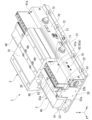
- FIG. 2 is a perspective view of a moving body and a linear motor module according to an embodiment.
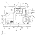
- 1 is a diagram showing a moving body and a linear motor module according to an embodiment as viewed from the X-axis direction.
- FIG. 1 is a perspective view of a linear motor module according to one embodiment.
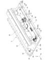
- FIG. 2 is a perspective view of a base member and a driving substrate according to an embodiment.
- 6 is a plan view of the base member and the drive substrate shown in FIG. 5 .
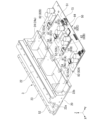
- FIG. 11 is a perspective view showing an assembly state of a base member and a drive substrate according to an embodiment.
- FIG. 1 is an overall view of a linear transport system 1 according to an embodiment.
- the linear transport system 1 includes a moving body 2 and a linear motor module 3.
- the moving body 2 is also called a mover unit.
- the linear motor module 3 is also called a stator unit.
- the linear motor module 3 includes a track body 30 that guides the moving body 2, and a linear encoder 60 arranged along the track body 30.
- the multiple linear motor modules 3 can be connected so that the multiple track bodies 30 are continuous.
- three linear motor modules 3 are connected.
- a connecting rail 31 is provided between the track body 30 of one linear motor module 3 and the track body 30 of an adjacent linear motor module 3.
- the moving body 2 can move along the adjacent track bodies 30 that are connected together by the connecting rail 31.
- the X-axis direction is the length direction of the track body 30 (the direction of movement of the moving body 2).
- the Y-axis direction is the width direction of the track body 30, which is perpendicular to the X-axis direction.
- the Z-axis direction is the height direction of the track body 30, which is perpendicular to the X-axis and Y-axis directions.
- Fig. 2 is a perspective view of the moving body 2 and the linear motor module 3 according to one embodiment.
- Fig. 3 is a view of the moving body 2 and the linear motor module 3 according to one embodiment as viewed from the X-axis direction.
- the moving body 2 includes a table 10 , a slider block 11 , a magnet 12 , and a linear scale 13 .
- the table 10 has a top plate portion that extends along the X-Y plane, and a pair of side walls that hang down from both ends of the top plate portion in the Y-axis direction.
- An object to be transported (not shown) can be fixed to the upper surface side of the top plate portion of the table 10.
- a slider block 11 is attached to the underside of the top plate of the table 10.
- the slider block 11 is engaged with the track body 30 so as to be movable in the X-axis direction.
- Recesses are formed on both side surfaces of the track body 30 in the Y-axis direction, and the slider block 11 has protrusions that engage with the recesses.
- a rolling element transfer path for endlessly transferring rolling elements may be formed between the recess of the track body 30 and the protrusion of the slider block 11.
- the rolling element transfer path may be provided, for example, in two rows, one on each side of the track body 30 in the Y-axis direction, or in four rows, two on each side of the track body 30 in the Y-axis direction.
- a magnet 12 is attached to the underside of the top plate of the table 10.
- the magnet 12 is disposed on the -Y side of the slider block 11.
- the magnetic poles of the magnet 12 face downward.
- the downward magnetic poles of the magnet 12 are arranged so that the N poles and S poles are alternately arranged in the X-axis direction.
- a linear scale 13 is attached to the inner wall surface of the side wall on the +Y side of the table 10.
- the linear scale 13 is formed in the shape of a thin rod extending in the X-axis direction.
- the linear scale 13 faces the detection unit 64a of the linear encoder 60 in the Y-axis direction.
- the linear scale 13 and the linear encoder 60 may be either optical or magnetic.
- the linear motor module 3 comprises a base member 20, a track body 30, a coil unit 40, a drive board 50, a linear encoder 60, and a cover 70.
- the base member 20 is preferably a lightweight metal member with heat dissipation properties, such as aluminum, and comprises a bottom plate portion 21, a pedestal portion 22, and a column portion 23.
- the bottom plate portion 21 is formed in a plate shape extending along the X-Y plane.
- the pedestal portion 22 stands upward (towards the +Z side) from the centre of the bottom plate portion 21 in the Y-axis direction.
- the track body 30 described above is attached to the top of the pedestal portion 22. As shown in FIG. 2, the pedestal portion 22 extends in the X-axis direction together with the track body 30.
- a first mounting portion 22a (step) is formed on the surface of the pedestal portion 22 facing the -Y side.
- the pillar portion 23 is disposed on the -Y side of the base portion 22, and stands upward (to the +Z side) from the bottom plate portion 21.
- the pillar portion 23 also extends in the X-axis direction together with the base portion 22 (first mounting portion 22a).
- the height of the top of the pillar portion 23 is the same as the height of the first mounting portion 22a.
- a support member 41 is installed between the pillar portion 23 and the first mounting portion 22a.
- the support member 41 is formed in an L-shape when viewed from the X-axis direction.
- the support member 41 supports the coil unit 40.
- the coil unit 40 faces the magnet 12 in the Z-axis direction.
- the coil unit 40 has U-phase, V-phase, and W-phase coil groups aligned along the X-axis direction. For example, multiple coil units 40 (four in this embodiment) are arranged side by side in the X-axis direction.
- the drive board 50 is disposed below the coil unit 40 (-Z side) and fixed onto the bottom plate 21.
- the drive board 50 includes a connector 81 that is connected to the coil unit 40 via a cable (not shown), and a motor driver 82 that controls the movement of the moving body 2 in the X-axis direction by passing a current through the coil unit 40 via the cable.
- the drive board 50 is disposed so as to penetrate the base 22 in the Y-axis direction (described later).
- the cover 70 covers the portion (base 51) of the drive board 50 that protrudes from the base 22 to the +Y side.
- the cover 70 is provided with various connectors that connect the drive board 50 to an external device (not shown).
- reference numerals 71 and 72 in FIG. 2 are communication connectors.
- Reference numeral 73 is a power connector.
- Reference numeral 74 is a USB connector.
- a second mounting portion 22b (step) is formed on the surface of the base portion 22 facing the +Y side.
- a linear encoder 60 is attached to the second mounting portion 22b. As shown in FIG. 3, the linear encoder 60 is formed in an L-shape when viewed from the X-axis direction.
- the linear encoder 60 includes a mounting base 61, a positioning plate 62, a sensor cover 63, and a position detection sensor 64.
- the mounting base 61 is formed in a plate shape extending along the X-Y plane, and is fixed to the second mounting portion 22b.
- a positioning plate 62 is attached to the +Y side end of the mounting base 61 by a screw member 61a.
- the positioning plate 62 stands upright above (on the +Z side) the +Y side end of the mounting base 61.
- the positioning plate 62 extends along the X-Z plane.
- the positioning plate 62 extends along the movement direction (X-axis direction) of the movable body 2 and faces the linear scale 13 in the Y-axis direction.
- a protective film 62a is attached to the surface of the positioning plate 62 facing the linear scale 13.
- the surface of the positioning plate 62 not facing the linear scale 13 is covered by a sensor cover 63.
- a position detection sensor 64 is arranged inside the sensor cover 63.
- FIG. 4 is a perspective view of a linear motor module 3 according to one embodiment. Note that in FIG. 4, the moving body 2 and the cover 70 are not shown in order to improve visibility.
- the reference numeral 75 in FIG. 4 denotes a mounting frame for attaching the cover 70 to the base member 20.
- the linear motor module 3 has four coil units 40A to 40D.
- the four coil units 40A to 40D are arranged side by side in the X-axis direction.
- FIG. 5 is a perspective view of the base member 20 and the drive board 50 according to one embodiment. Note that in FIG. 5, the coil unit 40, the support member 41, and the mounting frame 75 are not shown in order to improve visibility compared to FIG. 4.
- a plurality of spaces are formed at intervals in the X-axis direction on the side of the base portion 22.
- Each of the plurality of through holes 24 is located below (on the -Z side) the second mounting portion 22b and penetrates the base portion 22 in the Y-axis direction.
- the drive board 50 is fixed to the bottom plate portion 21 at multiple locations by screw members 91 and spacers 92.
- the drive board 50 is fixed in a state where it is slightly floating above (towards the +Z side) the bottom plate portion 21 by the spacers 92.
- Fig. 6 is a plan view of the base member 20 and the drive substrate 50 shown in Fig. 5.
- Fig. 7 is a perspective view showing the assembly of the base member 20 and the drive substrate 50 according to one embodiment.
- the drive substrate 50 is formed with a plurality of protrusions (hereinafter, comb-tooth portions 52 ) that are inserted into the plurality of through holes 24 .
- the drive substrate 50 has a base 51 extending in the X-axis direction and a number of comb-tooth portions 52 extending from the base 51 toward the -Y side.
- the drive substrate 50 of this embodiment has three comb-tooth portions 52 and is formed in an E-shape in plan view when viewed from the Z-axis direction.
- a motor driver 82 that controls the coil unit 40 is provided at the tip of the comb-tooth portion 52. As shown in FIG. 3, the motor driver 82 is disposed on the surface of the comb-tooth portion 52 facing the -Z side opposite the bottom plate portion 21, and is in contact with the bottom plate portion 21 via a heat transfer member 83. Heat generated by the motor driver 82 is transferred to the base member 20 via the heat transfer member 83 and dissipated.
- the base portion 22 has the three through holes 24 described above.
- the through holes 24 include two different sizes of through holes 24 (first through hole 24a and second through hole 24b).
- the first through hole 24a is formed at both ends of the base portion 22 in the X-axis direction.
- the second through hole 24b is formed in the center of the base portion 22 in the X-axis direction.
- the first through hole 24a is formed with a first length D1 in the X-axis direction.
- the second through hole 24b is formed with a second length D2 in the X-axis direction.
- the second length D2 is longer than the first length D1.
- the second length D2 is approximately twice the dimension of the first length D1.
- the comb tooth portions 52 include two different sizes of comb tooth portions 52 (first comb tooth portions 52a and second comb tooth portions 52b).
- the first comb tooth portions 52a are formed on both ends of the base portion 51 in the X-axis direction.
- the second comb tooth portions 52b are formed on the center of the base portion 51 in the X-axis direction.
- the first comb tooth portion 52a is formed with a first width W1 in the X-axis direction.
- the second through hole 24b is formed with a second width W2 in the X-axis direction.
- the second width W2 is larger than the first width W1.
- the second width W2 is approximately twice the dimension of the first width W1.
- the first comb tooth portion 52a can be inserted into the first through hole 24a.
- the first width W1 has a dimension slightly smaller than the first length D1.
- the second comb tooth portion 52b can be inserted into the second through hole 24b but cannot be inserted into the first through hole 24a.
- the second width W2 has a dimension slightly smaller than the second length D2 and larger than the first length D1.
- the second comb tooth portion 52b is provided with a greater number of motor drivers 82 than the first comb tooth portion 52a.
- the first comb tooth portion 52a arranged on the +X side is provided with a connector 81A connected to the coil unit 40A (see FIG. 4) via a cable (not shown), and a motor driver 82A that controls the coil unit 40A via the cable.
- Screw members 91 (and spacers 92) are arranged at four points around the motor driver 82A, and the motor driver 82A is in contact with the bottom plate portion 21 via the heat transfer member 83 while receiving a substantially uniform load.
- the first comb tooth portion 52a arranged on the -X side is provided with a connector 81D that is connected to the coil unit 40D via a cable (not shown), and a motor driver 82D that controls the coil unit 40D via the cable.
- Screw members 91 (and spacers 92) are arranged at four points around the motor driver 82D, and the motor driver 82D is in contact with the bottom plate portion 21 via the heat transfer member 83 while receiving a substantially uniform load.
- the second comb tooth portion 52b is provided with a connector 81B that is connected to the coil unit 40B via a cable (not shown), and a motor driver 82B that controls the coil unit 40B via the cable.
- the second comb tooth portion 52b is provided with a connector 81C that is connected to the coil unit 40C via a cable (not shown), and a motor driver 82B that controls the coil unit 40C via the cable.
- Screw members 91 are arranged at four locations around motor driver 82B and four locations around motor driver 82C, and motor driver 82B and motor driver 82C are subjected to a substantially uniform load and are in contact with the bottom plate portion 21 via the heat transfer member 83.
- the four screw members 91 arranged around motor driver 82B and the four screw members 91 arranged around motor driver 82C share two screw members 91c arranged between motor driver 82B and motor driver 82C. In other words, motor driver 82B and motor driver 82C are fixed with a total of six screw members 91.
- a beam member 90 is attached above three of the six screw members 91 that are positioned on an extension line of the first mounting portion 22a in the plan view shown in FIG. 6.
- the beam member 90 is detachably attached to the base portion 22 via screw members and forms part of the first mounting portion 22a. By removing the beam member 90 from the base portion 22, the three screw members 91 that are positioned on an extension line of the first mounting portion 22a can be tightened or untightened.
- At least a part of the control chip 84 that collectively controls the motor drivers 82A to 82D is provided in the second comb tooth portion 52b.
- the second comb tooth portion 52b is wider in the X-axis direction than the first comb tooth portion 52a, making it easier to layout the control chip 84.
- the dimension of the base 51 in the Y-axis direction can be made smaller than if the control chip 84 were laid out only on the base 51. Note that in this embodiment, the control chip 84 is laid out across the second comb tooth portion 52b and the base 51, but the control chip 84 may be laid out only on the second comb tooth portion 52b.
- multiple through holes 24 are formed on the side of the base 22, and the comb-tooth portion 52 of the drive board 50 is inserted into the through holes 24, allowing the drive board 50 to be positioned horizontally along the X-Y plane.
- This allows the height dimension of the linear motor module 3 to be reduced, as shown in FIG. 3.
- the drive board 50 can be positioned on both sides of the base 22 in the Y-axis direction. This allows the footprint of the linear motor module 3 to be smaller than if the drive board 50 were positioned only on one side of the base 22 in the Y-axis direction.
- the linear motor module 3 of this embodiment includes a track body 30 that guides the moving body 2, a plurality of coil units 40 arranged along the track body 30, a drive board 50 electrically connected to the plurality of coil units 40, and a base member 20 that supports the track body 30, the plurality of coil units 40, and the drive board 50.
- the base member 20 is provided with a pedestal portion 22 that supports the track body 30, and a plurality of through holes 24 are formed on the side of the pedestal portion 22 at intervals in the longitudinal direction of the track body 30, and the drive board 50 is formed with a plurality of comb tooth portions 52 that are inserted into the plurality of through holes 24.
- This configuration makes it possible to provide a linear motor module 3 that has a small footprint and a small height dimension.
- the comb tooth portion 52 is provided with a motor driver 82 that controls the coil unit 40.
- the motor driver 82 can be disposed below the coil unit 40, and the motor driver 82 and the coil unit 40 can be connected over a short distance.
- the base member 20 is provided with a bottom plate portion 21 that supports the pedestal portion 22, and the motor driver 82 is disposed on the surface of the comb tooth portion 52 that faces the bottom plate portion 21 and is in contact with the bottom plate portion 21 via a heat transfer member 83.
- heat generated by the motor driver 82 can be transferred to the bottom plate portion 21 via the heat transfer member 83 and dissipated efficiently.
- the plurality of through holes 24 include a first through hole 24a formed with a first length D1 in the length direction and a second through hole 24b formed with a second length D2 longer than the first length D1 in the length direction
- the plurality of comb teeth 52 include a first comb teeth 52a inserted into the first through hole 24a and a second comb teeth 52b inserted into the second through hole 24b and having a width in the length direction larger than that of the first comb teeth 52a.
- the second comb teeth 52b is provided with more motor drivers 82 than the first comb teeth 52a, and is provided with a control chip 84 that controls the motor drivers 82.
- the second comb teeth 52b is provided with two motor drivers 82B and 82C, and the control chip 84 is easily laid out. If four comb teeth 52 are formed corresponding to the four motor drivers 82, four through holes 24 must also be formed in the base 22. If the number of through holes 24 in the base portion 22 increases, the processing cost of the base member 20 increases and it becomes difficult to ensure the rigidity of the base portion 22 that supports the track body 30. Therefore, it is preferable to provide a wide second comb tooth portion 52b as in this embodiment.
- the linear transport system 1 of this embodiment also includes the linear motor module 3, and a moving body 2 that is guided along a track body 30 and includes a magnet 12 that can face multiple coil units 40, and the multiple linear motor modules 3 can be connected so that the multiple track bodies 30 are continuous.
- a linear transport system 1 with a small footprint and small height dimension can be constructed.
- a through hole has been described as the space, this is not limiting.
- the same effect can be obtained by inserting the protruding portion of the drive board into a hole or groove that does not penetrate the base.
Landscapes
- Engineering & Computer Science (AREA)
- Power Engineering (AREA)
- Physics & Mathematics (AREA)
- Chemical & Material Sciences (AREA)
- Combustion & Propulsion (AREA)
- Electromagnetism (AREA)
- Microelectronics & Electronic Packaging (AREA)
- Linear Motors (AREA)
Abstract
Description
リニア搬送システム1は、図1に示すように、移動体2と、リニアモータモジュール3と、を備えている。なお、移動体2は、可動子ユニットとも言う。また、リニアモータモジュール3は、固定子ユニットとも言う。リニアモータモジュール3は、移動体2を案内する軌道体30と、軌道体30に沿って配置されたリニアエンコーダ60と、を備えている。
図3に示すように、移動体2は、テーブル10と、スライダブロック11と、マグネット12と、リニアスケール13と、を備えている。
図6及び図7に示すように、駆動基板50には、複数の貫通孔24に挿入される複数の突出部(以下では、櫛歯部52)が形成されている。
2 移動体
3 リニアモータモジュール
12 マグネット
20 ベース部材
21 底板部
22 台座部
24 貫通孔(空間部)
24a 第1貫通孔
24b 第2貫通孔
30 軌道体
40 コイルユニット
50 駆動基板
52 櫛歯部(突出部)
52a 第1櫛歯部
52b 第2櫛歯部
82 モータドライバ
83 伝熱部材
84 制御チップ
D1 第1長さ
D2 第2長さ
W1 第1幅
W2 第2幅
Claims (5)
- 移動体を案内する軌道体と、
前記軌道体に沿って配置された複数のコイルユニットと、
前記複数のコイルユニットと電気的に接続された駆動基板と、
前記軌道体、前記複数のコイルユニット、及び前記駆動基板を支持するベース部材と、
を備え、
前記ベース部材には、前記軌道体を支持する台座部が設けられ、
前記台座部の側部には、前記軌道体が延びる長さ方向に間隔をあけて、複数の空間部が形成され、
前記駆動基板には、前記複数の空間部に挿入される複数の突出部が形成されている、
リニアモータモジュール。 - 前記突出部には、前記コイルユニットを制御するモータドライバが設けられている、
請求項1に記載のリニアモータモジュール。 - 前記ベース部材には、前記台座部を支持する底板部が設けられ、
前記モータドライバは、前記突出部の前記底板部と対向する面に配置されると共に、伝熱部材を介して前記底板部に接触している、
請求項2に記載のリニアモータモジュール。 - 前記複数の空間部は、
前記長さ方向において第1長さで形成された第1空間部と、
前記長さ方向において前記第1長さよりも長い、第2長さで形成された第2空間部と、
を備え、
前記複数の突出部は、
前記第1空間部に挿入される第1突出部と、
前記第2空間部に挿入され、前記第1突出部よりも前記長さ方向における幅が大きい第2突出部と、
を備え、
前記第2突出部には、前記第1突出部の個数より多い個数の前記モータドライバが設けられると共に、前記モータドライバを制御する制御チップの少なくとも一部が設けられている、
請求項2または3に記載のリニアモータモジュール。 - 請求項1~3のいずれか一項に記載のリニアモータモジュールと、
前記複数のコイルユニットと対向可能なマグネットを備え、前記軌道体に沿って案内される移動体と、
を備え、
複数の前記リニアモータモジュールは、複数の前記軌道体が連続するように連結可能である、
リニア搬送システム。
Priority Applications (3)
| Application Number | Priority Date | Filing Date | Title |
|---|---|---|---|
| DE112024002477.7T DE112024002477T5 (de) | 2023-06-09 | 2024-05-28 | Linearmotor-Modul und lineares Fördersystem |
| KR1020257040541A KR20260020930A (ko) | 2023-06-09 | 2024-05-28 | 리니어 모터 모듈 및 리니어 반송 시스템 |
| CN202480037290.9A CN121444325A (zh) | 2023-06-09 | 2024-05-28 | 线性马达模块以及线性搬运系统 |
Applications Claiming Priority (2)
| Application Number | Priority Date | Filing Date | Title |
|---|---|---|---|
| JP2023-095688 | 2023-06-09 | ||
| JP2023095688A JP2024176852A (ja) | 2023-06-09 | 2023-06-09 | リニアモータモジュール及びリニア搬送システム |
Publications (1)
| Publication Number | Publication Date |
|---|---|
| WO2024252984A1 true WO2024252984A1 (ja) | 2024-12-12 |
Family
ID=93795948
Family Applications (1)
| Application Number | Title | Priority Date | Filing Date |
|---|---|---|---|
| PCT/JP2024/019534 Ceased WO2024252984A1 (ja) | 2023-06-09 | 2024-05-28 | リニアモータモジュール及びリニア搬送システム |
Country Status (6)
| Country | Link |
|---|---|
| JP (1) | JP2024176852A (ja) |
| KR (1) | KR20260020930A (ja) |
| CN (1) | CN121444325A (ja) |
| DE (1) | DE112024002477T5 (ja) |
| TW (1) | TW202508212A (ja) |
| WO (1) | WO2024252984A1 (ja) |
Citations (2)
| Publication number | Priority date | Publication date | Assignee | Title |
|---|---|---|---|---|
| JP2013099192A (ja) * | 2011-11-04 | 2013-05-20 | Yamaha Motor Co Ltd | リニアモータおよびリニア搬送装置 |
| JP2021178721A (ja) * | 2020-05-15 | 2021-11-18 | ヤマハ発動機株式会社 | トラバーサ型水平循環装置 |
Family Cites Families (2)
| Publication number | Priority date | Publication date | Assignee | Title |
|---|---|---|---|---|
| JP5819748B2 (ja) | 2012-02-24 | 2015-11-24 | ヤマハ発動機株式会社 | リニアモータ並びにリニア搬送装置 |
| JP7651126B2 (ja) | 2021-12-24 | 2025-03-26 | 株式会社大一商会 | 遊技機 |
-
2023
- 2023-06-09 JP JP2023095688A patent/JP2024176852A/ja active Pending
-
2024
- 2024-05-28 WO PCT/JP2024/019534 patent/WO2024252984A1/ja not_active Ceased
- 2024-05-28 DE DE112024002477.7T patent/DE112024002477T5/de active Pending
- 2024-05-28 CN CN202480037290.9A patent/CN121444325A/zh active Pending
- 2024-05-28 KR KR1020257040541A patent/KR20260020930A/ko active Pending
- 2024-06-05 TW TW113120727A patent/TW202508212A/zh unknown
Patent Citations (2)
| Publication number | Priority date | Publication date | Assignee | Title |
|---|---|---|---|---|
| JP2013099192A (ja) * | 2011-11-04 | 2013-05-20 | Yamaha Motor Co Ltd | リニアモータおよびリニア搬送装置 |
| JP2021178721A (ja) * | 2020-05-15 | 2021-11-18 | ヤマハ発動機株式会社 | トラバーサ型水平循環装置 |
Also Published As
| Publication number | Publication date |
|---|---|
| DE112024002477T5 (de) | 2026-05-13 |
| TW202508212A (zh) | 2025-02-16 |
| CN121444325A (zh) | 2026-01-30 |
| KR20260020930A (ko) | 2026-02-12 |
| JP2024176852A (ja) | 2024-12-19 |
Similar Documents
| Publication | Publication Date | Title |
|---|---|---|
| JP6626982B2 (ja) | リニアコンベア装置 | |
| US7633188B2 (en) | Sliding device with onboard moving-magnet linear motor | |
| US9502953B2 (en) | Sliding device | |
| US6326708B1 (en) | Slider unit with built-in moving-coil linear motor | |
| JPH05227729A (ja) | 直流リニアモータ及びこれを具備した直動ユニット | |
| US6552449B2 (en) | Stage system with onboard linear motor | |
| US10906171B2 (en) | Motor unit and robot | |
| US7880344B2 (en) | X-Y table actuator | |
| US10340163B2 (en) | Mounting apparatus | |
| JP6676765B2 (ja) | リニアコンベアおよび中継ユニット | |
| JP4150411B2 (ja) | ステージ装置 | |
| JP4328364B2 (ja) | ステージ装置 | |
| JP2024176852A (ja) | リニアモータモジュール及びリニア搬送システム | |
| JP6129689B2 (ja) | リニアコンベア | |
| JP7603677B2 (ja) | コンベアテーブル移載装置、搬送システムおよびコンベアテーブル移載方法 | |
| CN104081636B (zh) | 线性马达以及组件安装装置 | |
| CN103997881A (zh) | 致动器、具备其的移载头、使用移载头的部件安装装置及方法 | |
| KR101078011B1 (ko) | 이송 유니트 및 이를 구비하는 이송 장치 | |
| JP7422001B2 (ja) | トラバーサ型水平循環装置 | |
| JP7127114B2 (ja) | 作業機 | |
| JPH0680529U (ja) | 駆動装置及びこれを具備したxy駆動装置 | |
| US10449667B2 (en) | Robot pedestal having support structure for controller | |
| JP5271966B2 (ja) | リニアモータを内蔵した立型xzスライド装置 | |
| JP4220505B2 (ja) | ステージ装置(stageapparatus) | |
| WO2024252991A1 (ja) | リニアエンコーダ及びリニア搬送システム |
Legal Events
| Date | Code | Title | Description |
|---|---|---|---|
| 121 | Ep: the epo has been informed by wipo that ep was designated in this application |
Ref document number: 24819215 Country of ref document: EP Kind code of ref document: A1 |
|
| WWE | Wipo information: entry into national phase |
Ref document number: CN2024800372909 Country of ref document: CN |
|
| WWE | Wipo information: entry into national phase |
Ref document number: 112024002477 Country of ref document: DE |
|
| WWP | Wipo information: published in national office |
Ref document number: 112024002477 Country of ref document: DE |
|
| 122 | Ep: pct application non-entry in european phase |
Ref document number: 24819215 Country of ref document: EP Kind code of ref document: A1 |