WO2024252979A1 - 伸縮性デバイス - Google Patents
伸縮性デバイス Download PDFInfo
- Publication number
- WO2024252979A1 WO2024252979A1 PCT/JP2024/019490 JP2024019490W WO2024252979A1 WO 2024252979 A1 WO2024252979 A1 WO 2024252979A1 JP 2024019490 W JP2024019490 W JP 2024019490W WO 2024252979 A1 WO2024252979 A1 WO 2024252979A1
- Authority
- WO
- WIPO (PCT)
- Prior art keywords
- stretchable
- wiring
- substrate
- elastic
- ratio
- Prior art date
- Legal status (The legal status is an assumption and is not a legal conclusion. Google has not performed a legal analysis and makes no representation as to the accuracy of the status listed.)
- Ceased
Links
Images

Classifications
-
- H—ELECTRICITY
- H05—ELECTRIC TECHNIQUES NOT OTHERWISE PROVIDED FOR
- H05K—PRINTED CIRCUITS; CASINGS OR CONSTRUCTIONAL DETAILS OF ELECTRIC APPARATUS; MANUFACTURE OF ASSEMBLAGES OF ELECTRICAL COMPONENTS
- H05K1/00—Printed circuits
- H05K1/02—Details
- H05K1/0277—Bendability or stretchability details
- H05K1/0283—Stretchable printed circuits
-
- H—ELECTRICITY
- H05—ELECTRIC TECHNIQUES NOT OTHERWISE PROVIDED FOR
- H05K—PRINTED CIRCUITS; CASINGS OR CONSTRUCTIONAL DETAILS OF ELECTRIC APPARATUS; MANUFACTURE OF ASSEMBLAGES OF ELECTRICAL COMPONENTS
- H05K1/00—Printed circuits
- H05K1/02—Details
-
- H—ELECTRICITY
- H05—ELECTRIC TECHNIQUES NOT OTHERWISE PROVIDED FOR
- H05K—PRINTED CIRCUITS; CASINGS OR CONSTRUCTIONAL DETAILS OF ELECTRIC APPARATUS; MANUFACTURE OF ASSEMBLAGES OF ELECTRICAL COMPONENTS
- H05K1/00—Printed circuits
- H05K1/02—Details
- H05K1/03—Use of materials for the substrate
-
- H—ELECTRICITY
- H05—ELECTRIC TECHNIQUES NOT OTHERWISE PROVIDED FOR
- H05K—PRINTED CIRCUITS; CASINGS OR CONSTRUCTIONAL DETAILS OF ELECTRIC APPARATUS; MANUFACTURE OF ASSEMBLAGES OF ELECTRICAL COMPONENTS
- H05K1/00—Printed circuits
- H05K1/02—Details
- H05K1/09—Use of materials for the conductive, e.g. metallic pattern
-
- H—ELECTRICITY
- H05—ELECTRIC TECHNIQUES NOT OTHERWISE PROVIDED FOR
- H05K—PRINTED CIRCUITS; CASINGS OR CONSTRUCTIONAL DETAILS OF ELECTRIC APPARATUS; MANUFACTURE OF ASSEMBLAGES OF ELECTRICAL COMPONENTS
- H05K2201/00—Indexing scheme relating to printed circuits covered by H05K1/00
- H05K2201/01—Dielectrics
- H05K2201/0104—Properties and characteristics in general
- H05K2201/0133—Elastomeric or compliant polymer
Definitions
- the present invention relates to a stretchable device.
- Stretchable devices that include a stretchable substrate and stretchable wiring arranged on the stretchable substrate have been known for some time.
- the proportion of the stretchable substrate relative to the stretchable wiring is relatively large, which can lead to a large contribution to the stretching behavior of the device as a whole. Therefore, if the stretchable substrate is prone to plastic deformation (i.e., prone to sagging) when stretched, this can cause the stretchable wiring arranged on the stretchable substrate to gradually stretch, which can increase the wiring resistance of the stretchable wiring.
- the stretchable substrate which is a component of a stretchable device, to be resistant to plastic deformation when the device stretches.
- the present invention aims to provide a stretchable device that has a stretchable substrate that is resistant to plastic deformation when stretched.
- a stretchable substrate and a stretchable wiring disposed on the stretchable substrate A stretchable device is provided, wherein the loss modulus E''(S) of the stretchable substrate is less than the loss modulus E''(W) of the stretchable wiring.
- the stretchable device makes it possible to make the stretchable substrate less susceptible to plastic deformation during stretching.
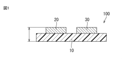
- FIG. 1 is a cross-sectional view that illustrates a stretchable device according to a first embodiment of the present invention.
- FIG. 2 is a cross-sectional view that illustrates a stretchable device according to a second embodiment of the present invention.
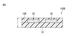
- FIG. 3 is a cross-sectional view that illustrates a stretchable device according to a third embodiment of the present invention.
- Fig. 1 is a cross-sectional view that typically illustrates the stretchable device according to the first embodiment of the present invention.
- the stretchable device 100 comprises a stretchable substrate 10 and at least one stretchable wiring disposed on the stretchable substrate 10.
- the at least one stretchable wiring include a first stretchable wiring 20 and a second stretchable wiring 30.
- above includes a state where it is located above an element and separated from it, i.e., above an element via another object, a state where it is located above an element with a gap, and a state where it is located directly above an element and in contact with it.
- stretchable wiring arranged on a stretchable substrate includes stretchable wiring in contact with the main surface of the stretchable substrate, and stretchable wiring that is not in direct contact with the main surface of the stretchable substrate and is separated from the main surface via another member (for example, a resin layer described below).
- the resin layer may be formed of at least one resin material selected from the group consisting of polyimide-based, epoxy-based, urethane-based, and acrylic-based resins.
- the resin layer may also be formed of an inorganic material such as alumina or silicon dioxide.
- the elastic substrate is a sheet-like or film-like substrate that can stretch, and is made of, for example, a resin material that has elasticity.
- resin materials for the elastic substrate include styrene-based elastomers, olefin-based elastomers, urethane-based elastomers, and silicone-based elastomers.
- the thickness of the elastic substrate is not particularly limited, but from the viewpoint of not inhibiting the expansion and contraction of the surface of the living body when attached to the living body, it is preferably 100 ⁇ m or less, and more preferably 50 ⁇ m or less. In addition, from the viewpoint of ensuring a certain strength, the thickness of the elastic substrate is preferably 10 ⁇ m or more.
- Each elastic wire contains conductive particles and resin.
- each elastic wire may be a mixture of metal powder such as Ag, Cu, Ni, etc. as conductive particles and a resin material such as an acrylic or silicone-based material.
- the average particle size of the conductive particles is not particularly limited, but is preferably 0.01 ⁇ m or more and 10 ⁇ m or less.
- the conductive particles are preferably spherical in shape.
- each elastic wire is not particularly limited, but is preferably 100 ⁇ m or less, and more preferably 50 ⁇ m or less.
- the thickness of each elastic wire is preferably 0.01 ⁇ m or more.
- the line width of each elastic wire is not particularly limited, but is preferably 0.1 ⁇ m or more, and more preferably 1 mm or less.
- the shape, etc. of each elastic wire is not particularly limited.
- the inventors of the present application conducted extensive research into a solution for providing a stretchable substrate that is resistant to plastic deformation when the stretchable device is stretched. As a result, the inventors of the present application focused on the viscoelastic properties, rather than the structure or shape of each component of the stretchable device, and came up with the present invention.
- the present invention is characterized in that in the stretchable device 100, the loss modulus E'' (S) of the stretchable substrate 10 is smaller than the loss modulus E'' (W) of the stretchable wiring 20, 30.
- the loss modulus as used in this specification refers to a measure of the energy lost from the components due to heat generation or the like during deformation, and refers to the degree of sagging of the stretchable substrate/stretchable wiring. The larger this value is, the more likely the components are to sag, and the smaller this value is, the less likely the components are to sag.
- the elastic substrate 10 is smaller than the loss modulus E'' (W) of the elastic wiring 20, 30, the elastic substrate is less susceptible to plastic deformation than the elastic wiring during stretching. In other words, the elastic substrate is less susceptible to sagging than the elastic wiring during stretching. This makes it possible to suppress gradual stretching of the elastic wiring 20, 30 arranged on the elastic substrate 10, and as a result, it is possible to suppress an increase in the wiring resistance of the elastic wiring 20, 30.
- the ratio of the loss modulus E''(S) of the elastic substrate 10 to the loss modulus E''(W) of the elastic wiring 20, 30 is smaller than 1, from the viewpoint of making the elastic substrate less susceptible to plastic deformation than the elastic wiring.
- the upper limit of the above ratio may be, for example, 0.6 or less.
- the upper limit of the above ratio is preferably 0.1 or less, and may be, for example, 0.07, more preferably 0.05 or less, and even more preferably 0.02 or less.
- the storage modulus E'(S) of the elastic substrate 10 is smaller than the storage modulus E'(W) of the elastic wiring 20, 30.
- the storage modulus refers to a measure of the energy stored in the components during deformation, and is a value that indicates the degree of hardness of the stretchable substrate/stretchable wiring. The larger this value is, the harder the components are in comparison, and the smaller this value is, the softer the components are.
- the stretchable substrate 10 can be selected to be relatively softer than the stretchable wirings 20 and 30, making it possible to prevent interference with the expansion of the stretchable wiring when the stretchable device 100 is stretched.
- the ratio of the storage modulus E'(S) of the elastic substrate 10 to the storage modulus E'(W) of the elastic wiring 20, 30 is 0.001 or more from the viewpoint of ensuring the elasticity of the substrate 10 itself, and is smaller than 1.0 from the viewpoint of making it softer than the elastic wiring.
- the upper limit of the above ratio is preferably 0.5 or less, for example 0.2 or less, from the viewpoint of appropriately softening the stretchable substrate 10. From the viewpoint of even more appropriately softening the stretchable substrate, the upper limit of the above ratio is more preferably 0.1 or less, for example 0.06, and even more preferably 0.05 or less.
- the ratio of the loss tangent tan ⁇ (S) of the stretchable substrate 10 to the loss tangent tan ⁇ (W) of the stretchable wiring 20, 30 is 0.01 or more from the viewpoint of ensuring the viscoelasticity of the stretchable substrate/stretchable wiring, and is 6.0 or less from the viewpoint of suppressing the rate of increase in wiring resistance after repeated stretching to a predetermined level or less.
- the loss tangent tan ⁇ in this specification refers to the ratio of the loss modulus E'' of the elastic wiring or elastic substrate to the storage modulus E' of the elastic wiring or elastic substrate, and indicates whether the elastic property or the viscous property is more prominent in the deformation of a certain viscoelastic body.
- the ratio of the loss modulus E''(S) of the elastic substrate to the loss modulus E''(W) of the elastic wiring is 0.1 or less
- the ratio of the loss tangent tan ⁇ (S) of the elastic substrate 10 to the loss tangent tan ⁇ (W) of the elastic wiring 20, 30 is preferably 1.5 or less, more preferably 1.0 or less, and even more preferably 0.5 or less, from the viewpoint of suitably suppressing the rate of increase in the wiring resistance after repeated stretching.
- the loss modulus E'' (S) of the stretchable substrate 10 is smaller than the loss modulus E'' (W) of the stretchable wirings 20, 30, when the stretchable substrate 10 and the stretchable wirings 20, 30 have predetermined values, the following characteristics can be obtained. Specifically, it is preferable that the ratio of the thickness of the stretchable wirings 20, 30 to the total thickness of the stretchable device 100 is 50% or less.
- This characteristic makes it possible to suppress an increase in wiring resistance that can occur when the proportion of stretchable wiring in the entire stretchable device 100 is relatively high. From the viewpoint of suitably suppressing such an increase in wiring resistance, it is more preferable that the thickness ratio of the above-mentioned stretchable wiring is 30% or less, and more preferably 15% or less. Furthermore, from the viewpoint of ensuring the wiring function in the stretchable device 100, it is preferable that the thickness ratio of the above-mentioned stretchable wiring is 5% or more.
- the ratio of the cross-sectional area of the stretchable wirings 20 and 30 to the total cross-sectional area of the stretchable device 100 is 50% or less.
- This feature makes it possible to suppress an increase in wiring resistance that can occur when the proportion of stretchable wiring in the entire stretchable device 100 is relatively high. From the viewpoint of suitably suppressing such an increase in wiring resistance, it is more preferable that the ratio of the cross-sectional area of the above-mentioned stretchable wiring is 30% or less, and more preferably 15% or less. Furthermore, from the viewpoint of ensuring the wiring function in the stretchable device 100, it is preferable that the ratio of the cross-sectional area of the above-mentioned stretchable wiring is 2% or more.
- the stretchable device 100 can be fabricated through the following steps. Specifically, first, a stretchable substrate 10 is prepared. The stretchable substrate 10 is selected to have a loss modulus E'' (S) smaller than the loss modulus E'' (W) of the stretchable wiring to be formed later.
- S loss modulus
- W loss modulus
- the covering layer 40 has viscoelastic properties similar to those of the elastic substrate 10.
- the loss modulus E'' (S) of the covering layer 40 is smaller than the loss modulus E'' (W) of the elastic wiring 20, 30.
- the stretchable substrate 10 and the covering layer 40 do not need to have the same material composition.
- the third embodiment is different from the first embodiment in that the third embodiment further includes a covering layer 10B that covers the stretchable substrate 10 and the stretchable wires 20, 30.
- This covering layer 10B can have the same function as the covering layer 40 in the second embodiment described above.
- the stretchable substrate 10 and the covering layer 10B can have the same material composition. Therefore, both the stretchable substrate 10 and the covering layer 10B can be made less susceptible to plastic deformation at the same level than the stretchable wiring during stretching. As a result, the stretchable device 100B as a whole can more suitably suppress an increase in the wiring resistance of the stretchable wirings 20 and 30, even if the covering layer 10B is present.
- the elastic substrate 10 was prepared.
- the elastic substrate 10 was selected to have a loss modulus E'' (S) smaller than the loss modulus E'' (W) of the elastic wiring to be formed later.
- a styrene-based elastomer was prepared as the elastic substrate 10.
- the elastic substrate 10 was selected to have the (1) loss modulus E′′(S), (2) storage modulus E'(S), and (3) loss tangent tan ⁇ (S) (E′′(S)/E'(S)) shown in Table 1.
- the wiring material used was a mixture of Ag particles and an acrylic resin containing Ag particles.
- the wiring material had a material composition that would result in a stretchable wiring having the (1) loss modulus E′′(W), (2) storage modulus E′(W), and (3) loss tangent tan ⁇ (W) (E′′(W)/E′(W)) shown in Table 1 after device fabrication.
- the wiring material was screen-printed on the prepared stretchable substrate 10, and then dried using a drying device. In this way, a stretchable device 100 was produced that included the stretchable substrate 10 and the stretchable wiring 20, 30 formed on the stretchable substrate (see FIG. 1).
- the (1) loss modulus E'', (2) storage modulus E', and (3) loss tangent tan ⁇ (E''/E') of the elastic substrate 10 and elastic wiring 20, 30 were measured using a dynamic viscoelasticity measuring device (RSA-G2, manufactured by TA Instruments). Specifically, the elastic substrate was vibrated up and down to deform and distort it, and the (1) loss modulus E'' and (2) storage modulus E' were measured from the shear stress waveform as a response and their phase difference. Furthermore, the (3) loss tangent tan ⁇ (E''/E') was calculated from these measured values.
- RSA-G2 dynamic viscoelasticity measuring device
- the ratio of the loss modulus E''(S) of the elastic substrate to the loss modulus E''(W) of the elastic wiring was 0.56.
- the ratio of the storage modulus E'(S) of the elastic substrate to the storage modulus E'(W) of the elastic wiring was 0.12.
- the ratio of the loss tangent tan ⁇ (S) of the elastic substrate to the loss tangent tan ⁇ (W) of the elastic wiring was 5.08.
- the thickness of the stretchable wiring was 30 ⁇ m, and the total thickness of the stretchable device was 100 ⁇ m.
- the cross-sectional area of the thickness of the stretchable wiring was 30% of the total cross-sectional area of the stretchable device.
- the wiring resistance of the stretchable wiring before (initial) use of the stretchable device 100 was measured by a four-terminal measurement method.
- the wiring resistance at this time was set to 100 (index) as a reference.
- the wiring resistance of the stretchable wiring was measured after the wiring was stretched by 10% and stretched 70 times.
- the wiring resistance (index) at this time was 150 with the wiring resistance (index) of 100 before (initial) use of the stretchable device 100 as a reference. From the above, the wiring resistance increase rate was +50%.
- the stretchable device 100 was able to stretch.
- Example 2 The following describes Example 2 and onwards, focusing on the differences from Example 1. Descriptions that overlap with those in Example 1 will be omitted or omitted.
- Example 2 differs from Example 1 in that the ratio of the thickness of the stretchable wire to the total thickness of the obtained stretchable device and the ratio of the cross-sectional area of the stretchable wire to the total cross-sectional area of the stretchable device were changed from 30% to 50%.
- the ratios of the loss modulus, storage modulus, and loss tangent of the stretchable wire and the stretchable substrate were the same as those of Example 1.
- the wiring resistance (index) after stretching was 200, based on the wiring resistance (index) of 100 before (initial) use of the stretchable device 100. From the above, the rate of increase in wiring resistance was +100%. Note that, as in Example 1, the stretchable device 100 was able to stretch.
- Example 3 differs from Example 1 in that the ratio of the thickness of the stretchable wire to the total thickness of the obtained stretchable device and the ratio of the cross-sectional area of the stretchable wire to the total cross-sectional area of the stretchable device were changed from 30% to 15%.
- the ratios of the loss modulus, storage modulus, and loss tangent of the stretchable wire and the stretchable substrate were the same as those of Example 1.
- the wiring resistance (index) after stretching was 135, based on the wiring resistance (index) of 100 before (initial) use of the stretchable device 100. From the above, the rate of increase in wiring resistance was +35%. Note that, similar to Example 1, the stretchable device 100 was able to stretch.
- Example 4 In Example 4, compared to Example 1, an elastic substrate 10 was selected that had the (1) loss modulus E′′(S), (2) storage modulus E'(S), and (3) loss tangent tan ⁇ (S) (E′′(S)/E'(S)) shown in Table 1.
- the ratio of the thickness of the stretchable wiring to the total thickness of the obtained stretchable device, the ratio of the cross-sectional area of the stretchable wiring to the total cross-sectional area of the stretchable device, and the (1) loss modulus E''(W), (2) storage modulus E'(W), and (3) loss tangent tan ⁇ of the stretchable wiring were the same as in Example 1.
- the ratio of the loss modulus E''(S) of the elastic substrate to the loss modulus E''(W) of the elastic wiring was 0.07.
- the ratio of the storage modulus E'(S) of the elastic substrate to the storage modulus E'(W) of the elastic wiring was 0.06.
- the ratio of the loss tangent tan ⁇ (S) of the elastic substrate to the loss tangent tan ⁇ (W) of the elastic wiring was 1.06.
- the wiring resistance (index) after stretching was 135, based on the wiring resistance (index) of 100 before (initial) use of the stretchable device 100. From the above, the rate of increase in wiring resistance was +35%. Note that, similar to Example 1, the stretchable device 100 was able to stretch.
- Example 5 The following describes Example 5 and onwards, focusing on the differences from Example 4. Any descriptions that overlap with those in Example 4 will be omitted or omitted.
- Example 5 differs from Example 4 in that the ratio of the thickness of the stretchable wiring to the total thickness of the obtained stretchable device and the ratio of the cross-sectional area of the stretchable wiring to the total cross-sectional area of the stretchable device were changed from 30% to 50%.
- the ratios of the loss modulus, storage modulus, and loss tangent of the stretchable wiring and the stretchable substrate were the same as those of Example 4.
- the wiring resistance (index) after stretching was 160, based on the wiring resistance (index) of 100 before (initial) use of the stretchable device 100. From the above, the rate of increase in wiring resistance was +60%. Note that, similar to Example 1, the stretchable device 100 was able to stretch.
- Example 6 differs from Example 4 in that the ratio of the thickness of the stretchable wiring to the total thickness of the obtained stretchable device and the ratio of the cross-sectional area of the stretchable wiring to the total cross-sectional area of the stretchable device were changed from 30% to 15%.
- the ratios of the loss modulus, storage modulus, and loss tangent of the stretchable wiring and the stretchable substrate were the same as those of Example 4.
- the wiring resistance (index) after stretching was 120, based on the wiring resistance (index) of 100 before (initial) use of the stretchable device 100. From the above, the rate of increase in wiring resistance was +20%. Note that, as in Example 1, the stretchable device 100 was able to stretch.
- Example 7 The following describes Examples 7 and onward, focusing on the differences from Example 1. Descriptions that overlap with those in Example 1 will be omitted or omitted.
- Example 7 In Example 7, compared to Example 1, an elastic substrate 10 was selected that had the (1) loss modulus E′′(S), (2) storage modulus E'(S), and (3) loss tangent tan ⁇ (S) (E′′(S)/E'(S)) shown in Table 1.
- the ratio of the thickness of the stretchable wiring to the total thickness of the obtained stretchable device, the ratio of the cross-sectional area of the stretchable wiring to the total cross-sectional area of the stretchable device, and the (1) loss modulus E''(W), (2) storage modulus E'(W), and (3) loss tangent tan ⁇ of the stretchable wiring were the same as in Example 1.
- the ratio of the loss modulus E''(S) of the elastic substrate to the loss modulus E''(W) of the elastic wiring was 0.05.
- the ratio of the storage modulus E'(S) of the elastic substrate to the storage modulus E'(W) of the elastic wiring was 0.06.
- the ratio of the loss tangent tan ⁇ (S) of the elastic substrate to the loss tangent tan ⁇ (W) of the elastic wiring was 0.78.
- the wiring resistance (index) after stretching was 125, based on the wiring resistance (index) of 100 before (initial) use of the stretchable device 100. From the above, the rate of increase in wiring resistance was +25%. Note that, similar to Example 1, the stretchable device 100 was able to stretch.
- Example 8 In Example 8, compared to Example 1, an elastic substrate 10 was selected that had the (1) loss modulus E′′(S), (2) storage modulus E'(S), and (3) loss tangent tan ⁇ (S) (E′′(S)/E'(S)) shown in Table 1.
- the ratio of the thickness of the stretchable wiring to the total thickness of the obtained stretchable device, the ratio of the cross-sectional area of the stretchable wiring to the total cross-sectional area of the stretchable device, and the (1) loss modulus E''(W), (2) storage modulus E'(W), and (3) loss tangent tan ⁇ of the stretchable wiring were the same as in Example 1.
- the ratio of the loss modulus E''(S) of the elastic substrate to the loss modulus E''(W) of the elastic wiring was 0.02.
- the ratio of the storage modulus E'(S) of the elastic substrate to the storage modulus E'(W) of the elastic wiring was 0.05.
- the ratio of the loss tangent tan ⁇ (S) of the elastic substrate to the loss tangent tan ⁇ (W) of the elastic wiring was 0.45.
- the wiring resistance (index) after stretching was 120, based on the wiring resistance (index) of 100 before (initial) use of the stretchable device 100. From the above, the rate of increase in wiring resistance was +20%. Note that, as in Example 1, the stretchable device 100 was able to stretch.
- Comparative Example 1 In Comparative Example 1, compared to Example 1, an elastic substrate was selected that had the (1) loss modulus E′′(S), (2) storage modulus E′(S), and (3) loss tangent tan ⁇ (S) (E′′(S)/E′(S)) shown in Table 1.
- the ratio of the thickness of the stretchable wiring to the total thickness of the obtained stretchable device, the ratio of the cross-sectional area of the stretchable wiring to the total cross-sectional area of the stretchable device, and the (1) loss modulus E''(W), (2) storage modulus E'(W), and (3) loss tangent tan ⁇ of the stretchable wiring were the same as in Example 1.
- the ratio of the loss modulus E''(S) of the elastic substrate to the loss modulus E''(W) of the elastic wiring was 1.52.
- the ratio of the storage modulus E'(S) of the elastic substrate to the storage modulus E'(W) of the elastic wiring was 0.91.
- the ratio of the loss tangent tan ⁇ (S) of the elastic substrate to the loss tangent tan ⁇ (W) of the elastic wiring was 1.68.
- the wiring resistance (index) after stretching was 220, based on the wiring resistance (index) of 100 before (initial) use of the stretchable device. From the above, the rate of increase in wiring resistance was +120%. As with Example 1, the stretchable device was able to stretch.
- Comparative Example 2 In Comparative Example 2, compared to Example 1, an elastic substrate was selected that had the (1) loss modulus E′′(S), (2) storage modulus E'(S), and (3) loss tangent tan ⁇ (S) (E′′(S)/E'(S)) shown in Table 1.
- the ratio of the thickness of the stretchable wiring to the total thickness of the obtained stretchable device, the ratio of the cross-sectional area of the stretchable wiring to the total cross-sectional area of the stretchable device, and the (1) loss modulus E''(W), (2) storage modulus E'(W), and (3) loss tangent tan ⁇ of the stretchable wiring were the same as in Example 1.
- the ratio of the loss modulus E''(S) of the elastic substrate to the loss modulus E''(W) of the elastic wiring was 2.4.
- the ratio of the storage modulus E'(S) of the elastic substrate to the storage modulus E'(W) of the elastic wiring was 4.1.
- the ratio of the loss tangent tan ⁇ (S) of the elastic substrate to the loss tangent tan ⁇ (W) of the elastic wiring was 0.6.
- Comparative Example 3 In Comparative Example 3, compared to Example 1, an elastic substrate was selected that had the (1) loss modulus E′′(S), (2) storage modulus E'(S), and (3) loss tangent tan ⁇ (S) (E′′(S)/E'(S)) shown in Table 1.
- the ratio of the thickness of the stretchable wiring to the total thickness of the obtained stretchable device, the ratio of the cross-sectional area of the stretchable wiring to the total cross-sectional area of the stretchable device, and the (1) loss modulus E''(W), (2) storage modulus E'(W), and (3) loss tangent tan ⁇ of the stretchable wiring were the same as in Example 1.
- the ratio of the loss modulus E''(S) of the elastic substrate to the loss modulus E''(W) of the elastic wiring was 9.5.
- the ratio of the storage modulus E'(S) of the elastic substrate to the storage modulus E'(W) of the elastic wiring was 23.0.
- the ratio of the loss tangent tan ⁇ (S) of the elastic substrate to the loss tangent tan ⁇ (W) of the elastic wiring was 0.4.
- the stretchable substrate is less susceptible to plastic deformation than the stretchable wiring when the stretchable device stretches, i.e., the stretchable substrate is less susceptible to sagging than the stretchable wiring when stretched. From the viewpoint of ensuring the tenacity of the stretchable substrate 10 itself, it is believed that the above ratio is preferably 0.001 or more.
- Comparative Examples 1 to 3 compared to Examples 1 to 8, it was found that in a stretchable device, when the loss modulus E'' (S) of the stretchable substrate is larger than the loss modulus E'' (W) of the stretchable wiring, the increase rate of the wiring resistance is +120%. Also, as shown in Comparative Examples 2 and 3, compared to the Examples, the storage modulus E' (S) of the stretchable substrate is considerably larger (about 35 times or more), and therefore it was found that stretching itself is not possible.
- the storage modulus E'(S) of the elastic substrate 10 is smaller than the storage modulus E'(W) of the elastic wiring 20, 30, specifically, when the ratio of the storage modulus E'(S) of the elastic substrate 10 to the storage modulus E'(W) of the elastic wiring 20, 30 is smaller than 1.0, the increase rate of the wiring resistance is +100% or less. This is believed to be due to the elastic substrate being softer than the elastic wiring when the stretchable device stretches.
- the ratio of the loss modulus E''(S) of the elastic substrate to the loss modulus E''(W) of the elastic wiring is 0.1 or less, and the ratio of the loss tangent tan ⁇ (S) of the elastic substrate 10 to the loss tangent tan ⁇ (W) of the elastic wiring 20, 30 is 1.5 or less (see Examples 4 to 8), it was found that the increase rate of the wiring resistance after repeated stretching can be suppressed more favorably than in Examples 1 to 3. Furthermore, when the ratio is 1.0 or less (see Examples 7 and 8), it was found that the increase rate of the wiring resistance after repeated stretching can be suppressed more favorably than in Examples 4 to 6. Furthermore, when the ratio is 0.5 or less (see Example 8), it was found that the increase rate of the wiring resistance after repeated stretching can be suppressed even more favorably than in Examples 4 to 7.
- Example 2 when the ratio of the thickness/cross-sectional area of the stretchable wirings 20, 30 to the total thickness/total cross-sectional area of the stretchable device 100 is 50%, the wiring resistance increase rate is +100%, whereas in Example 1, when this ratio is 30%, the wiring resistance increase rate is +50%. Also, in Example 3, when this ratio is 15%, the wiring resistance increase rate is +35%.
- Example 5 when the ratio of the thickness/cross-sectional area of the stretchable wirings 20, 30 to the total thickness/total cross-sectional area of the stretchable device 100 is 50%, the wiring resistance increase rate is +60%, whereas in Example 4, when this ratio is 30%, the wiring resistance increase rate is +35%. Also, in Example 6, when this ratio is 15%, the wiring resistance increase rate is +20%.
- the stretchable device may have the following features. ⁇ 1> A stretchable substrate and a stretchable wiring disposed on the stretchable substrate, A stretchable device, wherein the loss modulus E''(S) of the stretchable substrate is smaller than the loss modulus E''(W) of the stretchable wiring. ⁇ 2> The ratio of the loss modulus E''(S) of the elastic substrate to the loss modulus E''(W) of the elastic wiring is 0.001 or more and less than 1. The stretchable device according to ⁇ 1>. ⁇ 3> The stretchable device according to ⁇ 1> or ⁇ 2>, wherein the storage modulus E'(S) of the stretchable substrate is smaller than the storage modulus E'(W) of the stretchable wiring.
- Stretchable device 10 Stretchable substrate 20: First stretchable wiring 30: Second stretchable wiring 40: Covering layer 10B: Covering layer
Landscapes
- Engineering & Computer Science (AREA)
- Microelectronics & Electronic Packaging (AREA)
- Internal Circuitry In Semiconductor Integrated Circuit Devices (AREA)
- Structure Of Printed Boards (AREA)
Priority Applications (3)
| Application Number | Priority Date | Filing Date | Title |
|---|---|---|---|
| CN202480005236.6A CN120323089A (zh) | 2023-06-06 | 2024-05-28 | 伸缩性设备 |
| JP2025518024A JP7803463B2 (ja) | 2023-06-06 | 2024-05-28 | 伸縮性デバイス |
| US19/227,713 US20250301569A1 (en) | 2023-06-06 | 2025-06-04 | Stretchable device |
Applications Claiming Priority (2)
| Application Number | Priority Date | Filing Date | Title |
|---|---|---|---|
| JP2023093163 | 2023-06-06 | ||
| JP2023-093163 | 2023-06-06 |
Related Child Applications (1)
| Application Number | Title | Priority Date | Filing Date |
|---|---|---|---|
| US19/227,713 Continuation US20250301569A1 (en) | 2023-06-06 | 2025-06-04 | Stretchable device |
Publications (1)
| Publication Number | Publication Date |
|---|---|
| WO2024252979A1 true WO2024252979A1 (ja) | 2024-12-12 |
Family
ID=93795973
Family Applications (1)
| Application Number | Title | Priority Date | Filing Date |
|---|---|---|---|
| PCT/JP2024/019490 Ceased WO2024252979A1 (ja) | 2023-06-06 | 2024-05-28 | 伸縮性デバイス |
Country Status (4)
| Country | Link |
|---|---|
| US (1) | US20250301569A1 (https=) |
| JP (1) | JP7803463B2 (https=) |
| CN (1) | CN120323089A (https=) |
| WO (1) | WO2024252979A1 (https=) |
Citations (5)
| Publication number | Priority date | Publication date | Assignee | Title |
|---|---|---|---|---|
| JPH1140950A (ja) * | 1997-07-18 | 1999-02-12 | Hitachi Chem Co Ltd | 多層配線板 |
| JP2008243989A (ja) * | 2007-03-26 | 2008-10-09 | Arisawa Mfg Co Ltd | フレキシブルプリント配線板及び該フレキシブルプリント配線板を用いたスライド式携帯電話端末 |
| CN109439231A (zh) * | 2018-11-09 | 2019-03-08 | 吉林大学 | 一种基于碳材料/杂多酸/氨基酸的复合水基导电胶及其制备方法 |
| WO2020189790A1 (ja) * | 2019-03-20 | 2020-09-24 | 大日本印刷株式会社 | 配線基板及び配線基板の製造方法 |
| WO2022004504A1 (ja) * | 2020-06-30 | 2022-01-06 | 株式会社村田製作所 | 積層基板 |
-
2024
- 2024-05-28 CN CN202480005236.6A patent/CN120323089A/zh active Pending
- 2024-05-28 JP JP2025518024A patent/JP7803463B2/ja active Active
- 2024-05-28 WO PCT/JP2024/019490 patent/WO2024252979A1/ja not_active Ceased
-
2025
- 2025-06-04 US US19/227,713 patent/US20250301569A1/en active Pending
Patent Citations (5)
| Publication number | Priority date | Publication date | Assignee | Title |
|---|---|---|---|---|
| JPH1140950A (ja) * | 1997-07-18 | 1999-02-12 | Hitachi Chem Co Ltd | 多層配線板 |
| JP2008243989A (ja) * | 2007-03-26 | 2008-10-09 | Arisawa Mfg Co Ltd | フレキシブルプリント配線板及び該フレキシブルプリント配線板を用いたスライド式携帯電話端末 |
| CN109439231A (zh) * | 2018-11-09 | 2019-03-08 | 吉林大学 | 一种基于碳材料/杂多酸/氨基酸的复合水基导电胶及其制备方法 |
| WO2020189790A1 (ja) * | 2019-03-20 | 2020-09-24 | 大日本印刷株式会社 | 配線基板及び配線基板の製造方法 |
| WO2022004504A1 (ja) * | 2020-06-30 | 2022-01-06 | 株式会社村田製作所 | 積層基板 |
Also Published As
| Publication number | Publication date |
|---|---|
| CN120323089A (zh) | 2025-07-15 |
| US20250301569A1 (en) | 2025-09-25 |
| JP7803463B2 (ja) | 2026-01-21 |
| JPWO2024252979A1 (https=) | 2024-12-12 |
Similar Documents
| Publication | Publication Date | Title |
|---|---|---|
| TWI321148B (https=) | ||
| JP5705311B2 (ja) | 銅箔複合体及びそれに使用される銅箔、並びに成形体及びその製造方法 | |
| JP2012229485A5 (ja) | アルミニウム合金線、アルミニウム合金撚り線、被覆電線、及びワイヤーハーネス | |
| JP6223567B2 (ja) | プローブニードル及びプローブニードルの製造方法 | |
| CN104756610B (zh) | 印刷布线板 | |
| JP2014236103A (ja) | 伸縮性回路基板、その製造方法、及びそれによって製造された伸縮性回路基板 | |
| KR20180061003A (ko) | 전도성 유연 소자 | |
| CN105281076A (zh) | 连接器 | |
| JP2015055615A (ja) | エラスティックフレキシブルセンサ | |
| JP2023175747A (ja) | パラジウム-銅-銀-ルテニウム合金 | |
| WO2024252979A1 (ja) | 伸縮性デバイス | |
| JPWO2020004577A5 (https=) | ||
| CN116987454A (zh) | 一种晶圆减薄用胶带,其制备方法及一种晶圆研磨方法 | |
| US6815962B2 (en) | Connection/inspection device for semiconductor elements | |
| CN117545869A (zh) | 电气特性测试用导线及其制造方法 | |
| CN101238402A (zh) | 用于眼镜的结构部件、包含该结构部件的眼镜框架和用于制备结构部件和眼镜框架的方法 | |
| WO2020105206A1 (ja) | 伸縮性配線基板及び伸縮性配線基板の製造方法 | |
| JP7147767B2 (ja) | 導電性ペースト、伸縮性導体およびそれを用いた電子部品、衣服型電子機器 | |
| JP2012104227A5 (https=) | ||
| JP5321834B2 (ja) | 粘着テープ用基材フィルム | |
| WO2021187361A1 (ja) | 配線シート及びシート状ヒーター | |
| CN108957057A (zh) | 用于探针卡的探针及其制造方法 | |
| EP3924422A1 (en) | Polymeric compositions for cable jackets | |
| Hooper et al. | Family Spirasigmidae Hallmann, 1912 | |
| US20090069877A1 (en) | Electrode device for physiological use, in particular in cardiology |
Legal Events
| Date | Code | Title | Description |
|---|---|---|---|
| 121 | Ep: the epo has been informed by wipo that ep was designated in this application |
Ref document number: 24819210 Country of ref document: EP Kind code of ref document: A1 |
|
| WWE | Wipo information: entry into national phase |
Ref document number: 2025518024 Country of ref document: JP |
|
| WWE | Wipo information: entry into national phase |
Ref document number: 202480005236.6 Country of ref document: CN |
|
| WWP | Wipo information: published in national office |
Ref document number: 202480005236.6 Country of ref document: CN |
|
| NENP | Non-entry into the national phase |
Ref country code: DE |