WO2024252801A1 - 水素ガス製造システム及び水素ガス製造方法 - Google Patents
水素ガス製造システム及び水素ガス製造方法 Download PDFInfo
- Publication number
- WO2024252801A1 WO2024252801A1 PCT/JP2024/015484 JP2024015484W WO2024252801A1 WO 2024252801 A1 WO2024252801 A1 WO 2024252801A1 JP 2024015484 W JP2024015484 W JP 2024015484W WO 2024252801 A1 WO2024252801 A1 WO 2024252801A1
- Authority
- WO
- WIPO (PCT)
- Prior art keywords
- hydrogen gas
- raw water
- tank
- electrolysis
- electrolysis device
- Prior art date
- Legal status (The legal status is an assumption and is not a legal conclusion. Google has not performed a legal analysis and makes no representation as to the accuracy of the status listed.)
- Ceased
Links
Images


Classifications
-
- C—CHEMISTRY; METALLURGY
- C25—ELECTROLYTIC OR ELECTROPHORETIC PROCESSES; APPARATUS THEREFOR
- C25B—ELECTROLYTIC OR ELECTROPHORETIC PROCESSES FOR THE PRODUCTION OF COMPOUNDS OR NON-METALS; APPARATUS THEREFOR
- C25B9/00—Cells or assemblies of cells; Constructional parts of cells; Assemblies of constructional parts, e.g. electrode-diaphragm assemblies; Process-related cell features
- C25B9/17—Cells comprising dimensionally-stable non-movable electrodes; Assemblies of constructional parts thereof
- C25B9/19—Cells comprising dimensionally-stable non-movable electrodes; Assemblies of constructional parts thereof with diaphragms
- C25B9/23—Cells comprising dimensionally-stable non-movable electrodes; Assemblies of constructional parts thereof with diaphragms comprising ion-exchange membranes in or on which electrode material is embedded
-
- C—CHEMISTRY; METALLURGY
- C25—ELECTROLYTIC OR ELECTROPHORETIC PROCESSES; APPARATUS THEREFOR
- C25B—ELECTROLYTIC OR ELECTROPHORETIC PROCESSES FOR THE PRODUCTION OF COMPOUNDS OR NON-METALS; APPARATUS THEREFOR
- C25B1/00—Electrolytic production of inorganic compounds or non-metals
- C25B1/01—Products
- C25B1/02—Hydrogen or oxygen
- C25B1/04—Hydrogen or oxygen by electrolysis of water
-
- C—CHEMISTRY; METALLURGY
- C25—ELECTROLYTIC OR ELECTROPHORETIC PROCESSES; APPARATUS THEREFOR
- C25B—ELECTROLYTIC OR ELECTROPHORETIC PROCESSES FOR THE PRODUCTION OF COMPOUNDS OR NON-METALS; APPARATUS THEREFOR
- C25B15/00—Operating or servicing cells
- C25B15/02—Process control or regulation
-
- Y—GENERAL TAGGING OF NEW TECHNOLOGICAL DEVELOPMENTS; GENERAL TAGGING OF CROSS-SECTIONAL TECHNOLOGIES SPANNING OVER SEVERAL SECTIONS OF THE IPC; TECHNICAL SUBJECTS COVERED BY FORMER USPC CROSS-REFERENCE ART COLLECTIONS [XRACs] AND DIGESTS
- Y02—TECHNOLOGIES OR APPLICATIONS FOR MITIGATION OR ADAPTATION AGAINST CLIMATE CHANGE
- Y02E—REDUCTION OF GREENHOUSE GAS [GHG] EMISSIONS, RELATED TO ENERGY GENERATION, TRANSMISSION OR DISTRIBUTION
- Y02E60/00—Enabling technologies; Technologies with a potential or indirect contribution to GHG emissions mitigation
- Y02E60/30—Hydrogen technology
- Y02E60/36—Hydrogen production from non-carbon containing sources, e.g. by water electrolysis
Definitions
- the present invention relates to a hydrogen gas production system and a hydrogen gas production method that produce hydrogen gas by electrolyzing water.
- Stable isotopes of hydrogen atoms that compose naturally occurring water, hydrogen gas, etc. include hydrogen 1H (hereinafter also referred to as H), which has a mass number of 1 (the atomic nucleus is composed of only one proton), deuterium 2H (hereinafter also referred to as D), which has a mass number of 2 (the atomic nucleus is composed of one proton and one neutron), and tritium 3H (hereinafter also referred to as T), which has a mass number of 3 (the atomic nucleus is composed of one proton and two neutrons), and the content ratio of D or T is overwhelmingly smaller than that of H.
- H hydrogen 1H
- D deuterium 2H
- T tritium 3H
- T tritium 3H
- Patent Document 1 proposes a technology for generating deuterium-enriched hydrogen gas using a batch-type electrolysis device.
- the content ratio of D in the total hydrogen atoms in the finally obtained hydrogen gas will be equal to the content ratio of D in the total hydrogen atoms in the raw water.
- the electrodes need to be immersed in the raw water, and in the case of a flow-type electrolysis device, a minimum amount of liquid needs to be secured to drive the liquid delivery pump, and it is unavoidable that raw water will remain in the electrolysis device.
- the conventional hydrogen gas production method has the problem that the content ratio of D in the total hydrogen atoms in the obtained hydrogen gas is lower than the content ratio of D in the total hydrogen atoms in the raw water.
- the present invention aims to provide a hydrogen gas production system and method capable of producing hydrogen gas with a high recovery rate, the hydrogen gas having a deuterium D content equal to or greater than the content of deuterium D in the total hydrogen atoms in the raw water.
- the inventors of the present invention have made extensive research to solve the above problems, and have come to the following findings.
- the D content ratio of all hydrogen atoms in the hydrogen gas can be averaged over time.
- the D content ratio of all hydrogen atoms in the raw water remaining in the device is higher than before the start of electrolysis. Therefore, as the amount of raw water in the electrolysis device decreases, hydrogen gas with a higher D content ratio can be continuously generated by replenishing the electrolysis device with deuterium-enriched water (raw water). By combining these, hydrogen gas with a D content ratio equal to or higher than the D content ratio of all hydrogen atoms in the raw water can be produced without discarding the generated hydrogen gas.
- the gist of the present invention is as follows:
- the electrolysis device comprises: an electrolysis cell in which an anode chamber containing an anode and a cathode chamber containing a cathode are adjacent to each other via an ion exchange membrane; A second tank that accommodates the raw water supplied from the first tank; a liquid supply pipe connecting the second tank and the anode chamber and supplying the raw water from the second tank to the anode chamber; a return pipe connecting the anode chamber and the second tank and for returning the raw water from the anode chamber to the second tank; a circulation device that circulates the raw water between the second tank and the anode chamber via the liquid supply pipe and the return pipe;
- the hydrogen gas production system according to [1] above.
- a method for producing hydrogen gas comprising continuously supplying the hydrogen gas generated in the electrolysis device to the storage tank before and after the replenishment, and storing the hydrogen gas generated in the electrolysis device in the storage tank before and after the replenishment.
- the electrolysis device includes an electrolysis cell in which an anode chamber accommodating an anode and a cathode chamber accommodating a cathode are adjacent to each other via an ion exchange membrane, and a second tank accommodating the raw water supplied from the first tank;
- the raw water is supplied from the second tank to the anode chamber via a liquid supply piping connecting the second tank and the anode chamber, while the raw water is returned from the anode chamber to the second tank via a return piping connecting the anode chamber and the second tank, thereby circulating the raw water between the second tank and the anode chamber via the liquid supply piping and the return piping.
- the hydrogen gas production system and method of the present invention make it possible to produce hydrogen gas with a deuterium D content equal to or greater than the content of deuterium D in the total hydrogen atoms in the raw water with a high recovery rate.
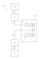
- FIG. 1 is a schematic diagram showing the device configuration of a hydrogen gas production system according to one embodiment of the present invention.
- 1 is a schematic diagram showing the device configuration of a hydrogen gas production system having a flow-type electrolyzer in one embodiment of the present invention.
- FIG. FIG. 1 is a schematic diagram showing the device configuration of a hydrogen gas production system having a batch-type electrolyzer in one embodiment of the present invention.
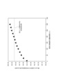
- 1 is a graph showing the content ratio of D to all hydrogen atoms in hydrogen gas obtained versus the operating time of an electrolyzer in a comparative example.
- [Hydrogen gas production system and hydrogen gas production method] 1 shows the configuration of a hydrogen gas production system 100 according to an embodiment of the present invention.
- the hydrogen gas production system 100 includes a first tank 10 for storing raw water containing heavy water, an electrolyzer 30 for generating hydrogen gas by electrolyzing the raw water, a reservoir 50 for storing hydrogen gas, a liquid delivery device 20 for delivering raw water from the first tank 10 to the electrolyzer 30, and an air delivery device 40 for delivering hydrogen gas generated in the electrolyzer 30 to the reservoir 50.
- the hydrogen gas production system 100 is further characterized in that the liquid delivery device 20 is controlled to replenish raw water from the first tank 10 to the electrolyzer 30 as the amount of raw water remaining in the electrolyzer 30 decreases, the air delivery device 40 is controlled to continuously deliver hydrogen gas generated in the electrolyzer 30 to the reservoir 50 before and after the replenishment, and the reservoir 50 stores the hydrogen gas generated in the electrolyzer 30 before and after the replenishment of raw water.
- piping 60 connects the first tank 10 and the liquid delivery device 20, and defines a flow path through which raw water is delivered.
- Pipe 62 connects the liquid delivery device 20 and the electrolysis device 30, and defines a flow path through which raw water is delivered.
- Pipe 64 connects the electrolysis device 30 and the gas delivery device 40, and defines a flow path through which hydrogen gas is delivered.
- Pipe 66 connects the gas delivery device 40 and the reservoir 50, and defines a flow path through which hydrogen gas is delivered.
- the hydrogen gas production method can be suitably carried out using the hydrogen gas production system 100, and includes the steps of storing raw water containing heavy water in the first tank 10, sending the raw water from the first tank 10 to the electrolysis device 30, electrolyzing the raw water in the electrolysis device 30 to generate hydrogen gas, and sending the hydrogen gas generated in the electrolysis device 30 to the reservoir 50.
- the hydrogen gas production method is further characterized in that as the amount of raw water remaining in the electrolysis device 30 decreases, the raw water is replenished from the first tank 10 to the electrolysis device 30, and the hydrogen gas generated in the electrolysis device 30 is continuously sent to the reservoir 50 before and after the replenishment, and the reservoir 50 stores the hydrogen gas generated in the electrolysis device 30 before and after the replenishment.
- the raw water is water containing heavy water (D 2 O). If the content ratio of D in the total hydrogen atoms in the raw water (deuterium enriched water) is 90 [atom% D] or more, hydrogen gas in which D is sufficiently concentrated can be obtained, which is preferable.
- the upper limit of the content ratio of D in the total hydrogen atoms in the raw water (deuterium enriched water) is not particularly limited, but from an industrial point of view, the content ratio of D in the total hydrogen atoms in the raw water (deuterium enriched water) is approximately 99.98 [atom% D] or less.
- the raw water may contain a portion of semi-heavy water (HDO), and the D contained in semi-heavy water is also included in the above content ratio.
- the raw water may contain a supporting salt such as potassium hydroxide or hypochlorite depending on the electrolysis device used.
- the ratio of D to all hydrogen atoms in the raw water can be determined by subjecting the raw water to analysis using a nuclear magnetic resonance spectrometer (e.g., manufactured by JEOL), measuring the areas of H and D atoms, and calculating the ratio of the area of D atoms to the total area of H and D atoms.
- a nuclear magnetic resonance spectrometer e.g., manufactured by JEOL
- the first tank 10 is a device that stores raw water, and is connected to the liquid delivery device 20 by a pipe 60.
- the material of the first tank 10 is not particularly limited, but for example, a material that is easily permeable to air components, such as a resin, may allow moisture in the air to pass through, which may reduce the content ratio of D in the total hydrogen atoms in the raw water in the first tank 10. Therefore, it is preferable to use a material such as SUS or glass that is not permeable to air components.
- the liquid delivery device 20 is a device that delivers raw water from the first tank 10 to the electrolyzer 30, and is connected to the first tank 10 via a pipe 60 and to the electrolyzer 30 via a pipe 62.
- the liquid delivery device 20 may be, for example, a liquid delivery pump.
- the liquid delivery process is a process of delivering raw water from the first tank 10 to the electrolyzer 30 using the liquid delivery device 20. By delivering raw water, the amount of water in the electrolyzer 30 is increased so that the electrolyzer 30 can operate.
- the amount of liquid to be delivered is preferably the upper limit amount that the electrolyzer 30 can accommodate.
- the liquid delivery device 20 is controlled to replenish raw water from the first tank 10 to the electrolysis device 30 as the amount of raw water remaining in the electrolysis device 30 decreases during the process of electrolysis of raw water by the electrolysis device 30.
- the control for replenishing raw water is not limited, but the following mode is preferable.
- the electrolysis device 30 is preferably equipped with a liquid level sensor.
- the liquid level sensor detects the liquid level of the raw water in the electrolysis device 30 (i.e., the amount of raw water remaining) and outputs a signal when the liquid level falls to a predetermined threshold value.
- the output signal of the liquid level sensor is sent to a control unit (CPU, etc.), and the control unit operates the liquid delivery device 20 in response to the input of the signal from the liquid level sensor to replenish raw water to the electrolysis device 30.
- the output signal of the liquid level sensor may be in the form of light, sound, etc., or an operator may recognize the output signal of the liquid level sensor and operate the liquid delivery device 20 to replenish raw water to the electrolysis device 30.
- the timing for replenishing the raw water is preferably when the liquid level falls to a predetermined threshold value.
- the threshold value of the liquid level may be the liquid level at the operating limit of the electrolysis device 30 described later, or may be set to a value higher than the operating limit so that the raw water can be replenished before the operating limit is reached.
- an operator may periodically check the liquid level, and when it is determined that the liquid level has decreased, the liquid delivery device 20 may be operated to replenish the raw water.
- the consumption rate of the raw water can be determined based on the capacity of the electrolysis device 30 and the electrolysis conditions, the consumption amount of the raw water may be calculated in advance, and after performing electrolysis for a certain period of time, the control unit may automatically operate the liquid delivery device 20 or an operator may operate it to replenish the raw water.
- the timing for replenishing the raw water is not particularly limited, and the raw water may be constantly replenished during electrolysis.
- the electrolyzer 30 When the electrolyzer 30 generates hydrogen gas, light water (H 2 O) contained in the raw water is decomposed first due to the isotope effect. Therefore, the content ratio of D to all hydrogen atoms in the raw water remaining in the electrolyzer 30 increases over time.
- the electrolyzer 30 is able to electrolyze raw water having a higher content ratio of D by replenishing the raw water by the liquid delivery device 20, and as a result, hydrogen gas having a higher content ratio of D than the hydrogen gas obtained before the replenishing of the raw water is obtained.
- the hydrogen gas production system 100 has a pipe 60 that connects the first tank 10 and the liquid delivery device 20 and defines a flow path through which the raw water is delivered from the first tank 10 to the liquid delivery device 20.
- the hydrogen gas production system 100 further has a pipe 62 that connects the liquid delivery device 20 and the electrolysis device 30 and defines a flow path through which the raw water is delivered from the liquid delivery device 20 to the electrolysis device 30.
- the material of the pipes 60 and 62 is not particularly limited, but a material that is easily permeable to air components, such as resin, may allow moisture in the air to pass through, which may reduce the content ratio of D in the total hydrogen atoms in the raw water in the pipes 60 and 62, so it is preferable to use a SUS or glass material that is not permeable to air components.
- the electrolyzer 30 is a device that electrolyzes raw water, and is connected to the liquid delivery device 20 via a pipe 62, and to the air delivery device 40 via a pipe 64.
- the electrolyzer 30 is not particularly limited as long as it is capable of electrolyzing raw water to generate hydrogen gas, and a conventionally known electrolyzer can be used.
- a flow type and a batch type are widely used: a flow type and a batch type.
- FIG. 2 shows a schematic diagram of a hydrogen gas production system 102 having a flow-type electrolyzer 30A in one embodiment of the present invention.
- the configuration other than that of the electrolyzer 30A is the same as that of FIG. 1.
- the electrolyzer 30A has an electrolysis cell 80, and the electrolysis cell 80 has a configuration in which an anode chamber 82 that accommodates an anode and a cathode chamber 84 that accommodates a cathode are adjacent to each other via an ion exchange membrane 86.
- the electrolyzer 30A has a second tank 32 that accommodates raw water supplied from the first tank 10 by the liquid supply device 20, and a circulation device 38 that circulates raw water between the second tank 32 and the anode chamber 82 via the liquid supply pipe 34 and the return pipe 36.
- the liquid supply pipe 34 is a pipe that connects the second tank 32 and the anode chamber 82 and supplies raw water from the second tank 32 to the anode chamber 82.
- the return pipe 36 connects the second tank 32 and the anode chamber 82, and is a pipe for returning the raw water from the anode chamber 82 to the second tank 32.
- the circulation device 38 may be, for example, a liquid delivery pump.
- the location where the circulation device 38 is installed is not particularly limited, but it is installed, for example, in the liquid delivery pipe 34 as shown in FIG. 2.
- FIG. 3 shows a schematic diagram of a hydrogen gas production system 104 having a batch-type electrolyzer 30B in one embodiment of the present invention.
- the configuration other than that of the electrolyzer 30B is the same as that of FIG. 1.
- the electrolyzer 30B has an electrolysis cell 90, which contains an anode 92 and a cathode 94, and which are immersed in raw water 96 also contained in the electrolysis cell 90.
- Pipe 68 is used when oxygen gas by-produced at the anode 92 of the electrolysis cell 90 is discharged.
- the electrolysis step is a step of generating hydrogen gas using the electrolysis device 30.
- the circulation device 38 it is preferable to operate the circulation device 38 at all times during electrolysis to circulate the raw water between the second tank 32 and the anode chamber 82.
- raw water is decomposed into oxygen gas and hydrogen ions in the anode chamber 82 in the electrolysis cell 80 by the oxidation reaction shown in the following formula (1).
- the hydrogen ions generated in the anode chamber 82 permeate the ion exchange membrane 86 and move to the cathode chamber 84, where they become hydrogen gas by the reduction reaction shown in the following formula (2).
- the hydrogen gas generated in the cathode chamber 84 is sent to the reservoir 50 via the pipes 64 and 66 by the gas supply device 40.
- the hydrogen gas obtained by electrolysis of heavy water ( D2O ) is deuterium gas ( D2 ).
- the hydrogen gas obtained by electrolysis of semi-heavy water is semi-deuterium gas (HD).
- the obtained hydrogen gas is also deuterium-enriched hydrogen gas (hydrogen gas having a higher proportion of deuterium D than normal hydrogen gas).
- the oxidation reaction shown in the above formula (1) occurs at the anode 92 in the electrolysis cell 90
- the reduction reaction shown in the above formula (2) occurs at the cathode 94.
- the electrolysis cell 90 does not have an ion exchange membrane 86, but has spaces on the anode side and the upper part of the cathode side, as shown in FIG. 3.
- the oxygen gas generated at the anode 92 and the hydrogen gas generated at the cathode 94 do not mix with each other, and the oxygen gas moves to the space above the anode 92 side, and the hydrogen gas moves to the space above the cathode 94 side.
- the hydrogen gas is sent to the reservoir 50 by the gas supply device 40 through the pipes 64 and 66.
- the oxygen gas by-produced at the anode 92 of the electrolysis cell 90 is discharged through the pipe 68.
- the electrolysis process begins when the electrolysis device 30 has contained raw water up to its upper limit, the raw water in the electrolysis device 30 is decomposed and gradually decreases.
- the liquid delivery device 20 replenishes raw water from the first tank 10 to the electrolysis device 30. The raw water is replenished before the amount of raw water remaining in the electrolysis device 30 reaches the operating limit of the electrolysis device 30.
- the operating limit refers to a state in which the minimum amount of raw water required to drive the circulation device 38 is reached in the case of the flow-type electrolysis device 30A, or a state in which the amount of raw water reaches such a level that the anode 92 or cathode 94 rises above the liquid surface of the raw water in the case of the batch-type electrolysis device 30B.
- the electrolysis device 30 When hydrogen gas is generated in the electrolysis process, light water (H 2 O) contained in the raw water is decomposed first due to the isotope effect. Therefore, the content ratio of D to all hydrogen atoms in the raw water remaining in the electrolysis device 30 increases over time.
- the electrolysis device 30 is able to electrolyze raw water having a higher content ratio of D by replenishing the raw water to the electrolysis device 30 using the liquid delivery device 20, and as a result, hydrogen gas having a higher content ratio of D is obtained than the hydrogen gas obtained before the replenishing of the raw water.
- the gas supply device 40 is a device that supplies hydrogen gas from the electrolyzer 30 to the reservoir 50, and is connected to the electrolyzer 30 by a pipe 64, and to the reservoir 50 by a pipe 66.
- the gas supply device 40 is controlled so as to continuously supply hydrogen gas generated in the electrolyzer 30 to the reservoir 50 before and after the liquid supply device 20 replenishes the electrolyzer 30 with raw water.
- a booster can be used as the gas supply device 40.
- the gas supply process is a process of supplying hydrogen gas generated in the electrolyzer 30 to the reservoir 50 using the gas supply device 40.
- the gas supply to the reservoir 50 is continuously performed before and after the liquid supply device 20 replenishes the raw water to the electrolyzer 30.
- the hydrogen gas stored in the reservoir 50 has an averaged content ratio of D to all hydrogen atoms in the continuously obtained hydrogen gas.
- the hydrogen gas generated in the electrolyzer 30 generally has a pressure of about 0.3 MPa.
- the inside of the reservoir 50 is reduced in pressure before the operation of the electrolyzer 30, and immediately after the operation of the electrolyzer 30, the reservoir 50 is filled with the self-pressure of the generated hydrogen gas, and the hydrogen gas can be further pressurized by the gas supply device 40 and filled into the reservoir 50.
- the hydrogen gas production system 100 has a pipe 64 that connects the electrolyzer 30 and the gas supply device 40 and defines a flow path through which hydrogen gas is supplied from the electrolyzer 30 to the gas supply device 40.
- the material of the pipe 64 is not particularly limited, but since a material that is easily permeable to air components, such as resin, leads to a decrease in the purity of the obtained hydrogen gas, it is preferable to use a SUS or glass material that is not permeable to air components.
- devices such as a mass flow controller or a back pressure valve for controlling the amount of hydrogen gas sent, a purifier for removing moisture and air components from the generated hydrogen gas, and a compressor for increasing the pressure of the generated hydrogen gas may be appropriately installed.
- the reservoir 50 is a device for storing hydrogen gas obtained by electrolysis, and is connected to the gas supply device 40 by a pipe 66.
- the reservoir 50 continuously stores the hydrogen gas generated in the electrolysis device 30 before and after the liquid supply device 20 replenishes the raw water to the electrolysis device 30.
- the content ratio of D to all hydrogen atoms in the stored hydrogen gas is averaged.
- the material of the reservoir 50 is not particularly limited, but materials that are easily permeable to air components, such as resin, will lead to a decrease in the purity of the resulting hydrogen gas, so it is preferable to use SUS or glass materials that are not permeable to air components.
- the hydrogen gas production system 100 has a pipe 66 that connects the gas supply device 40 and the reservoir 50 and defines a flow path through which hydrogen gas is supplied from the gas supply device 40 to the reservoir 50.
- the material of the pipe 66 is not particularly limited, but since a material that is easily permeable to air components, such as resin, leads to a decrease in the purity of the obtained hydrogen gas, it is preferable to use a SUS or glass material that is not permeable to air components.
- Hydrogen gas having a content ratio of D equal to or greater than the content ratio of deuterium D in all hydrogen atoms in the raw water (deuterium-enriched water) can be obtained without discarding the hydrogen gas generated in the initial stage.
- the content ratio of D in all hydrogen atoms in the raw water is 90 [atom% D] or more
- hydrogen gas having a content ratio of D in all hydrogen atoms in the hydrogen gas of 90 [atom% D] or more can be obtained, which is preferable.
- the upper limit of the content ratio of D in all hydrogen atoms in the hydrogen gas is not particularly limited, and the content ratio of D in all hydrogen atoms in the hydrogen gas can be 100.00 [atom% D] or less. As described above, from an industrial point of view, the upper limit of the content ratio of D in all hydrogen atoms in the raw water is 99.98 [atom% D], and in this case, the content ratio of D in all hydrogen atoms in the obtained hydrogen gas can be 99.98 [atom% D] or more.
- the hydrogen gas may contain a portion of deuterium gas (HD), and the D contained in deuterium gas is also included in the above content ratio. The content ratio of D to all hydrogen atoms in the hydrogen gas can be determined in the same manner as for the raw water.
- Example 1 Using an apparatus with the same configuration as that shown in Fig. 2, 940 g of raw water (deuterium-enriched water) with a D content of 99.84 atom%D was first charged into the electrolyzer, and the first operation of the apparatus was started. Six hours after the start of operation, the D content of the hydrogen gas stored in the reservoir was measured and found to be 99.81 atom%D. At this time, 400 g of raw water remained in the electrolyzer, and the D content of the remaining raw water was 99.92 atom%D.
- 940 g of raw water (deuterium-enriched water) with a D content of 99.84 atom%D was first charged into the electrolyzer, and the first operation of the apparatus was started. Six hours after the start of operation, the D content of the hydrogen gas stored in the reservoir was measured and found to be 99.81 atom%D. At this time, 400 g of raw water remained in the electrolyzer, and the D content of the remaining raw water was 99.92 atom%D.
- Recovery rate of hydrogen gas generated from the electrolysis device which has a D content equal to or higher than the D content in all hydrogen atoms in the raw water in the reservoir, was ⁇ 99%.
- the recovery rate was calculated as follows.
- Recovery rate [%] (amount of hydrogen gas recovered in the storage tank [L] / total amount of hydrogen gas generated by the electrolysis device [L]) ⁇ 100 [%]
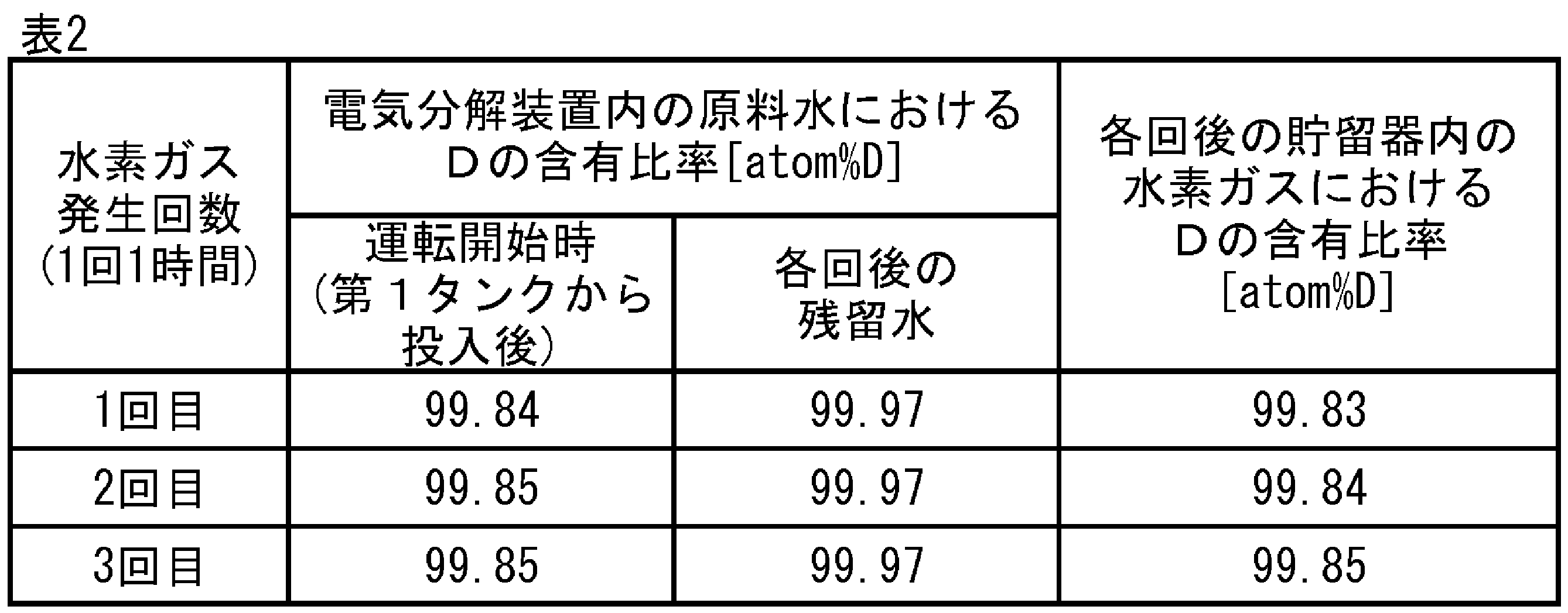
- Example 2 Using an apparatus with the same configuration as that shown in Fig. 3, 100 g of raw water (deuterium-enriched water) with a D content of 99.84 atom% D was first charged into the electrolyzer, and the first operation of the apparatus was started. One hour after the start of operation, the D content of the hydrogen gas stored in the reservoir was measured and found to be 99.83 atom% D. At this time, 12 g of raw water remained in the electrolyzer, and the D content of the remaining raw water was 99.97 atom% D.
- raw water deuterium-enriched water
- the recovery rate was calculated in the same manner as in Example 1.
- the recovery rate of hydrogen gas generated from the electrolysis device which has a D content equal to or greater than the D content of all hydrogen atoms in the raw water in the reservoir, was ⁇ 99%.
- Example 1 Among the devices used in Example 1, the electrolysis device was used to electrolyze raw water (deuterium-enriched water) having a content ratio of D of 99.84 atom%D, without using the first tank and the reservoir. The generated hydrogen gas was sampled periodically to measure the content ratio of D.
- FIG. 4 shows the content ratio of D in the total hydrogen atoms in the hydrogen gas obtained versus the operation time of the electrolysis device. As a result, it took 3.8 hours or more of operation until the content ratio of D in the generated hydrogen gas reached 99.84 atom%D, which is the content ratio of D in the raw water.
- Hydrogen gas production system 102 Hydrogen gas production system having a flow type electrolyzer 104 Hydrogen gas production system having a batch type electrolyzer 10 First tank 20 Liquid delivery device 30 Electrolyzer 30A Flow type electrolyzer 30B Batch type electrolyzer 32 Second tank 34 Liquid delivery pipe 36 Return pipe 38 Circulation device 40 Gas delivery device 50 Reservoir 60 Pipe 62 Pipe 64 Pipe 66 Pipe 68 Pipe 80 Flow type electrolysis cell 82 Anode chamber 84 Cathode chamber 86 Ion exchange membrane 90 Batch type electrolysis cell 92 Anode 94 Cathode 96 Raw water
Landscapes
- Chemical & Material Sciences (AREA)
- Engineering & Computer Science (AREA)
- Chemical Kinetics & Catalysis (AREA)
- Electrochemistry (AREA)
- Materials Engineering (AREA)
- Metallurgy (AREA)
- Organic Chemistry (AREA)
- Inorganic Chemistry (AREA)
- Automation & Control Theory (AREA)
- Electrolytic Production Of Non-Metals, Compounds, Apparatuses Therefor (AREA)
Abstract
原料水と同等以上の重水素Dの含有比率を有する水素ガスを高い回収率で製造することが可能な水素ガス製造システムを提供する。本発明の水素ガス製造システム100は、重水を含む原料水を収容する第1タンク10と、原料水を電気分解して水素ガスを発生させる電気分解装置30と、水素ガスを貯留する貯留器50と、原料水を第1タンク10から電気分解装置30に送液する送液装置20と、電気分解装置30で発生した水素ガスを貯留器50に送気する送気装置40と、を有し、送液装置20が、電気分解装置30内に残存する原料水の減少に伴い、第1タンク10から電気分解装置30に原料水を補充するように制御され、送気装置40が、補充の前後にわたり継続的に、電気分解装置30で発生した水素ガスを貯留器50に送気するように制御され、貯留器50が、補充の前後にわたり電気分解装置30で発生した水素ガスを貯留する。
Description
本発明は、水を電気分解することにより水素ガスを製造する水素ガス製造システム及び水素ガス製造方法に関する。
天然に存在する水や水素ガス等を構成する水素原子の安定同位体として、質量数が1である(原子核が1個の陽子のみからなる)水素1H(以下、Hとも記す)と、質量数が2である(原子核が1個の陽子と1個の中性子からなる)重水素2H(以下、Dとも記す)と、質量数が3である(原子核が1個の陽子と2個の中性子からなる)三重水素3H(以下、Tとも記す)があり、D又はTの含有比率はHに比べて圧倒的に小さい。半導体製造分野や原子力分野においては、Dが特に有効となる用途が知られている。このため、Dの含有比率を高めた水や水素ガスを低コストで製造することが求められている。
ところで、一般的な水素ガスの製造方法としては、水を電気分解して酸素ガスと水素ガスとを発生させる電気分解法がよく用いられている。電気分解法において、重水素濃縮水(通常の純水よりも重水素Dの含有比率が高められた水)を原料水として用いることで、重水素濃縮水素ガス(通常の水素ガスよりも重水素Dの含有比率が高められた水素ガス)を製造することが可能であることが知られている。特許文献1には、バッチ式の電気分解装置を用いて重水素濃縮水素ガスを発生させる技術が提案されている。
しかしながら、原料水としての重水素濃縮水を電気分解して重水素濃縮水素ガスを得る場合、同位体効果により、原料水に含まれる軽水(H2O)が先に分解される。そのため、得られる水素ガス中の全水素原子に占めるDの含有比率は、電気分解開始直後は低く、徐々に上昇していくという経時変化が生じる。従来、重水素濃縮水素ガスを製造する際は、目的とするDの含有比率に達するまでに発生させた水素ガスを廃棄していたため、水素ガスの回収率が低く、製造コストが高くなるという課題があった。
また、理論上は、電気分解装置に一度投入した重水素濃縮水(原料水)に含まれるDの全量を水素ガスに変換できれば、最終的に得られる水素ガス中の全水素原子に占めるDの含有比率は、原料水中の全水素原子に占めるDの含有比率と同等となる。しかし、実際の電気分解装置の運用においては、特許文献1に記載されるようなバッチ式の電気分解装置の場合は電極が原料水に浸かる必要があり、フロー式の電気分解装置の場合は送液ポンプを駆動させるために最低限の液量を確保する必要があり、電気分解装置内に原料水が残留することが避けられない。そのため、投入した原料水の全量を電気分解することは不可能であり、前述した経時変化が生じる事象も踏まえると、従来の水素ガス製造方法では、得られる水素ガス中の全水素原子に占めるDの含有比率は、原料水中の全水素原子に占めるDの含有比率よりも低くなるという課題があった。
上記課題を鑑みて、本発明は、原料水中の全水素原子に占める重水素Dの含有比率と同等以上の重水素Dの含有比率を有する水素ガスを高い回収率で製造することが可能な水素ガス製造システム及び水素ガス製造方法を提供することを目的とする。
本発明者らは、上記課題を解決するべく鋭意検討した結果、以下の知見を得た。電気分解装置から得られる水素ガスを貯留器で貯留することで、水素ガス中の全水素原子に占めるDの含有比率を経時的に平均化することができる。また、電気分解装置の運用上、装置内に残留した原料水中の全水素原子に占めるDの含有比率は、電気分解開始前よりも高くなっているため、電気分解装置内の原料水の量の減少に伴い、電気分解装置に重水素濃縮水(原料水)を補充することによって、Dの含有比率がより高い水素ガスを継続的に発生させることができる。これらを組み合わせることで、発生した水素ガスを廃棄することなく、原料水中の全水素原子に占めるDの含有比率と同等以上のDの含有比率を有する水素ガスを製造することができる。
すなわち、本発明の要旨構成は次のとおりである。
[1]重水を含む原料水を収容する第1タンクと、
前記原料水を電気分解して水素ガスを発生させる電気分解装置と、
前記水素ガスを貯留する貯留器と、
前記原料水を前記第1タンクから前記電気分解装置に送液する送液装置と、
前記電気分解装置で発生した前記水素ガスを前記貯留器に送気する送気装置と、
を有し、
前記送液装置が、前記電気分解装置内に残存する前記原料水の量の減少に伴い、前記第1タンクから前記電気分解装置に前記原料水を補充するように制御され、
前記送気装置が、前記補充の前後にわたり継続的に、前記電気分解装置で発生した前記水素ガスを前記貯留器に送気するように制御され、前記貯留器が、前記補充の前後にわたり前記電気分解装置で発生した前記水素ガスを貯留することを特徴とする水素ガス製造システム。
前記原料水を電気分解して水素ガスを発生させる電気分解装置と、
前記水素ガスを貯留する貯留器と、
前記原料水を前記第1タンクから前記電気分解装置に送液する送液装置と、
前記電気分解装置で発生した前記水素ガスを前記貯留器に送気する送気装置と、
を有し、
前記送液装置が、前記電気分解装置内に残存する前記原料水の量の減少に伴い、前記第1タンクから前記電気分解装置に前記原料水を補充するように制御され、
前記送気装置が、前記補充の前後にわたり継続的に、前記電気分解装置で発生した前記水素ガスを前記貯留器に送気するように制御され、前記貯留器が、前記補充の前後にわたり前記電気分解装置で発生した前記水素ガスを貯留することを特徴とする水素ガス製造システム。
[2]前記電気分解装置が、
陽極を収容する陽極室と陰極を収容する陰極室とがイオン交換膜を介して隣り合う電気分解セルと、
前記第1タンクから供給される前記原料水を収容する第2タンクと、
前記第2タンクと前記陽極室とを連結し、前記第2タンクから前記陽極室に前記原料水を供給するための送液配管と、
前記陽極室と前記第2タンクとを連結し、前記陽極室から前記第2タンクに前記原料水を返送するための返送配管と、
前記送液配管及び前記返送配管を介して、前記第2タンクと前記陽極室との間で前記原料水を循環させる循環装置と、
を有する、上記[1]に記載の水素ガス製造システム。
陽極を収容する陽極室と陰極を収容する陰極室とがイオン交換膜を介して隣り合う電気分解セルと、
前記第1タンクから供給される前記原料水を収容する第2タンクと、
前記第2タンクと前記陽極室とを連結し、前記第2タンクから前記陽極室に前記原料水を供給するための送液配管と、
前記陽極室と前記第2タンクとを連結し、前記陽極室から前記第2タンクに前記原料水を返送するための返送配管と、
前記送液配管及び前記返送配管を介して、前記第2タンクと前記陽極室との間で前記原料水を循環させる循環装置と、
を有する、上記[1]に記載の水素ガス製造システム。
[3]重水を含む原料水を第1タンクに収容する工程と、
前記原料水を前記第1タンクから電気分解装置に送液する工程と、
前記電気分解装置にて前記原料水を電気分解して水素ガスを発生させる電気分解工程と、
前記電気分解装置で発生した前記水素ガスを貯留器に送気する工程と、
を有し、
前記電気分解装置内に残存する前記原料水の量の減少に伴い、前記第1タンクから前記電気分解装置に前記原料水を補充し、
前記補充の前後にわたり継続的に、前記電気分解装置で発生した前記水素ガスを前記貯留器に送気し、前記貯留器が、前記補充の前後にわたり前記電気分解装置で発生した前記水素ガスを貯留することを特徴とする水素ガス製造方法。
前記原料水を前記第1タンクから電気分解装置に送液する工程と、
前記電気分解装置にて前記原料水を電気分解して水素ガスを発生させる電気分解工程と、
前記電気分解装置で発生した前記水素ガスを貯留器に送気する工程と、
を有し、
前記電気分解装置内に残存する前記原料水の量の減少に伴い、前記第1タンクから前記電気分解装置に前記原料水を補充し、
前記補充の前後にわたり継続的に、前記電気分解装置で発生した前記水素ガスを前記貯留器に送気し、前記貯留器が、前記補充の前後にわたり前記電気分解装置で発生した前記水素ガスを貯留することを特徴とする水素ガス製造方法。
[4]前記電気分解装置が、陽極を収容する陽極室と陰極を収容する陰極室とがイオン交換膜を介して隣り合う電気分解セルと、前記第1タンクから供給される前記原料水を収容する第2タンクと、を有し、
前記電気分解工程では、前記第2タンクと前記陽極室とを連結する送液配管を介して、前記第2タンクから前記陽極室に前記原料水を供給しつつ、前記陽極室と前記第2タンクとを連結する返送配管を介して、前記陽極室から前記第2タンクに前記原料水を返送することで、前記送液配管及び前記返送配管を介して、前記第2タンクと前記陽極室との間で前記原料水を循環させる、上記[3]に記載の水素ガス製造方法。
前記電気分解工程では、前記第2タンクと前記陽極室とを連結する送液配管を介して、前記第2タンクから前記陽極室に前記原料水を供給しつつ、前記陽極室と前記第2タンクとを連結する返送配管を介して、前記陽極室から前記第2タンクに前記原料水を返送することで、前記送液配管及び前記返送配管を介して、前記第2タンクと前記陽極室との間で前記原料水を循環させる、上記[3]に記載の水素ガス製造方法。
本発明の水素ガス製造システム及び水素ガス製造方法によれば、原料水中の全水素原子に占める重水素Dの含有比率と同等以上の重水素Dの含有比率を有する水素ガスを高い回収率で製造することが可能である。
以下、本発明に係る水素ガス製造システム及び水素ガス製造方法の実施形態を説明する。なお、以下に説明する実施形態は、本発明を具体化した一例であって、その具体例をもって本発明の構成を限定するものではない。
[水素ガス製造システム及び水素ガス製造方法]
図1に本発明の一実施形態における水素ガス製造システム100の装置構成を示す。水素ガス製造システム100は、重水を含む原料水を収容する第1タンク10と、原料水を電気分解して水素ガスを発生させる電気分解装置30と、水素ガスを貯留する貯留器50と、原料水を第1タンク10から電気分解装置30に送液する送液装置20と、電気分解装置30で発生した水素ガスを貯留器50に送気する送気装置40と、を有する。水素ガス製造システム100はさらに、送液装置20が、電気分解装置30内に残存する原料水の量の減少に伴い、第1タンク10から電気分解装置30に原料水を補充するように制御され、送気装置40が、補充の前後にわたり継続的に、電気分解装置30で発生した水素ガスを貯留器50に送気するように制御され、貯留器50が、原料水の補充の前後にわたり電気分解装置30で発生した水素ガスを貯留することを特徴とする。
図1に本発明の一実施形態における水素ガス製造システム100の装置構成を示す。水素ガス製造システム100は、重水を含む原料水を収容する第1タンク10と、原料水を電気分解して水素ガスを発生させる電気分解装置30と、水素ガスを貯留する貯留器50と、原料水を第1タンク10から電気分解装置30に送液する送液装置20と、電気分解装置30で発生した水素ガスを貯留器50に送気する送気装置40と、を有する。水素ガス製造システム100はさらに、送液装置20が、電気分解装置30内に残存する原料水の量の減少に伴い、第1タンク10から電気分解装置30に原料水を補充するように制御され、送気装置40が、補充の前後にわたり継続的に、電気分解装置30で発生した水素ガスを貯留器50に送気するように制御され、貯留器50が、原料水の補充の前後にわたり電気分解装置30で発生した水素ガスを貯留することを特徴とする。
図1において、配管60は、第1タンク10と送液装置20とを連結し、原料水が送液される流路を区画する配管である。配管62は、送液装置20と電気分解装置30とを連結し、原料水が送液される流路を区画する配管である。配管64は、電気分解装置30と送気装置40とを連結し、水素ガスが送気される流路を区画する配管である。配管66は、送気装置40と貯留器50とを連結し、水素ガスが送気される流路を区画する配管である。
本発明の一実施形態に係る水素ガス製造方法は、水素ガス製造システム100を用いて好適に実施することができ、重水を含む原料水を第1タンク10に収容する工程と、原料水を第1タンク10から電気分解装置30に送液する工程と、電気分解装置30にて原料水を電気分解して水素ガスを発生させる電気分解工程と、電気分解装置30で発生した水素ガスを貯留器50に送気する工程と、を有する。水素ガス製造方法はさらに、電気分解装置30内に残存する原料水の量の減少に伴い、第1タンク10から電気分解装置30に原料水を補充し、補充の前後にわたり継続的に、電気分解装置30で発生した水素ガスを貯留器50に送気し、貯留器50が、補充の前後にわたり電気分解装置30で発生した水素ガスを貯留することを特徴とする。
(原料水)
原料水は、重水(D2O)を含む水とする。原料水(重水素濃縮水)中の全水素原子に占めるDの含有比率が90[atom%D]以上であると、Dが十分に濃縮された水素ガスを得ることができ、好ましい。原料水(重水素濃縮水)中の全水素原子に占めるDの含有比率の上限は特に限定されないが、工業的な観点から、原料水(重水素濃縮水)中の全水素原子に占めるDの含有比率は、概ね99.98[atom%D]以下である。なお、原料水は、半重水(HDO)を一部含んでいてもよく、半重水に含まれるDも上記含有比率に含まれる。また、使用する電気分解装置に応じて原料水に水酸化カリウムや次亜塩素酸塩などの支持塩が含まれていてもよい。
原料水は、重水(D2O)を含む水とする。原料水(重水素濃縮水)中の全水素原子に占めるDの含有比率が90[atom%D]以上であると、Dが十分に濃縮された水素ガスを得ることができ、好ましい。原料水(重水素濃縮水)中の全水素原子に占めるDの含有比率の上限は特に限定されないが、工業的な観点から、原料水(重水素濃縮水)中の全水素原子に占めるDの含有比率は、概ね99.98[atom%D]以下である。なお、原料水は、半重水(HDO)を一部含んでいてもよく、半重水に含まれるDも上記含有比率に含まれる。また、使用する電気分解装置に応じて原料水に水酸化カリウムや次亜塩素酸塩などの支持塩が含まれていてもよい。
原料水中の全水素原子に占めるDの含有比率は、原料水を核磁気共鳴分光装置(例えば日本電子製)による分析に供して、H原子及びD原子の面積を測定し、H原子及びD原子の総面積に対するD原子の面積の比率を計算することで求めることができる。
(第1タンク10)
第1タンク10は、原料水を収容する装置であり、送液装置20と配管60により連結されたものとする。第1タンク10の材質は特に限定されないが、例えば樹脂などの空気成分を透過しやすい材質は、空気中の水分を透過させることで第1タンク10内の原料水中の全水素原子に占めるDの含有比率が下がってしまう恐れがあるため、空気成分を透過しないSUSやガラス材料を使用することが好ましい。
第1タンク10は、原料水を収容する装置であり、送液装置20と配管60により連結されたものとする。第1タンク10の材質は特に限定されないが、例えば樹脂などの空気成分を透過しやすい材質は、空気中の水分を透過させることで第1タンク10内の原料水中の全水素原子に占めるDの含有比率が下がってしまう恐れがあるため、空気成分を透過しないSUSやガラス材料を使用することが好ましい。
(送液装置20及び送液工程)
送液装置20は、原料水を第1タンク10から電気分解装置30に送液する装置であり、第1タンク10と配管60により連結され、電気分解装置30と配管62により連結されたものとする。送液装置20は、例えば送液ポンプであり得る。送液工程は、原料水を第1タンク10から電気分解装置30に、送液装置20を用いて送液する工程である。原料水を送液して電気分解装置30内の水量を増やし、電気分解装置30が稼働できるようにする。送液する液量は、電気分解装置30の収容できる上限量とすることが好ましい。
送液装置20は、原料水を第1タンク10から電気分解装置30に送液する装置であり、第1タンク10と配管60により連結され、電気分解装置30と配管62により連結されたものとする。送液装置20は、例えば送液ポンプであり得る。送液工程は、原料水を第1タンク10から電気分解装置30に、送液装置20を用いて送液する工程である。原料水を送液して電気分解装置30内の水量を増やし、電気分解装置30が稼働できるようにする。送液する液量は、電気分解装置30の収容できる上限量とすることが好ましい。
送液装置20は、電気分解装置30による原料水の電気分解の過程で、電気分解装置30内に残存する原料水の量の減少に伴い、第1タンク10から電気分解装置30に原料水を補充するように制御されるものとする。原料水を補充する制御としては、限定されるものではないが、以下のような態様が好ましい。電気分解装置30は、液面センサーが設置されていることが好ましい。液面センサーは、電気分解装置30内の原料水の液面(すなわち、残留している原料水の液量)を感知し、液面高さが所定の閾値まで下がると信号を出力する。液面センサーの出力信号は制御部(CPU等)に送られ、制御部は、液面センサーからの信号の入力を受けて、送液装置20を稼働し、原料水を電気分解装置30に補充する。あるいは、液面センサーの出力信号は光や音等の形式でもよく、作業員が液面センサーの出力信号を認識して、作業員が送液装置20を稼働することで、原料水を電気分解装置30に補充してもよい。
原料水を補充するタイミングとしては、上記のような液面センサーが電気分解装置30に設置されている場合は、液面高さが所定の閾値まで下がった時とすることが好ましい。ここで、液面高さの閾値とは、後述する電気分解装置30の運転限界の液面としてもよく、運転限界に達する前に原料水を補充できるように、運転限界よりも高い値を設定してもよい。液面センサーが電気分解装置30に設置されていない場合は、作業員が定期的に液量を確認し、液量が減少していると判断した場合に、送液装置20を稼働して原料水を補充してもよい。原料水の消費速度は、電気分解装置30の容量や電気分解の条件等によって求めることができるため、あらかじめ原料水の消費量を計算し、一定時間電気分解を行った後に、送液装置20を制御部が自動で稼働し、又は作業員が稼働して、原料水を補充してもよい。なお、原料水を補充するタイミングは特に限定されず、電気分解中に常時補充を行ってもよい。
電気分解装置30が水素ガスを発生させる際、同位体効果により原料水に含まれる軽水(H2O)が先に分解される。そのため、電気分解装置30に残留する原料水中の全水素原子に占めるDの含有比率は、経時的に高くなる。電気分解装置30による原料水の電気分解の過程で、送液装置20によって原料水を電気分解装置30に補充することで、電気分解装置30はDの含有比率がより高い原料水を電気分解することが可能となり、結果として、原料水補充前に得られた水素ガスよりもDの含有比率が高い水素ガスが得られる。
(配管60,62)
水素ガス製造システム100は、第1タンク10と送液装置20とを連結し、原料水が第1タンク10から送液装置20に送液される流路を区画する配管60を有する。水素ガス製造システム100はさらに、送液装置20と電気分解装置30とを連結し、原料水が送液装置20から電気分解装置30に送液される流路を区画する配管62を有する。配管60,62の材質は特に限定されないが、例えば樹脂などの空気成分を透過しやすい材質は、空気中の水分を透過させることで配管60,62内の原料水中の全水素原子に占めるDの含有比率が下がってしまう恐れがあるため、空気成分を透過しないSUSやガラス材料を使用することが好ましい。
水素ガス製造システム100は、第1タンク10と送液装置20とを連結し、原料水が第1タンク10から送液装置20に送液される流路を区画する配管60を有する。水素ガス製造システム100はさらに、送液装置20と電気分解装置30とを連結し、原料水が送液装置20から電気分解装置30に送液される流路を区画する配管62を有する。配管60,62の材質は特に限定されないが、例えば樹脂などの空気成分を透過しやすい材質は、空気中の水分を透過させることで配管60,62内の原料水中の全水素原子に占めるDの含有比率が下がってしまう恐れがあるため、空気成分を透過しないSUSやガラス材料を使用することが好ましい。
(電気分解装置30)
電気分解装置30は、原料水を電気分解する装置であり、送液装置20と配管62によって連結され、送気装置40と配管64によって連結されたものとする。電気分解装置30は、原料水を電気分解して水素ガスを発生させるものであれば特に限定されず、従来公知のものを用いることができる。一般に、電気分解装置30はフロー式とバッチ式の2種が広く使用されている。
電気分解装置30は、原料水を電気分解する装置であり、送液装置20と配管62によって連結され、送気装置40と配管64によって連結されたものとする。電気分解装置30は、原料水を電気分解して水素ガスを発生させるものであれば特に限定されず、従来公知のものを用いることができる。一般に、電気分解装置30はフロー式とバッチ式の2種が広く使用されている。
図2に、本発明の一実施形態における、フロー式の電気分解装置30Aを有する水素ガス製造システム102の模式図を示す。電気分解装置30A以外の構成については図1と同様である。電気分解装置30Aは電気分解セル80を有し、電気分解セル80は、陽極を収容する陽極室82と陰極を収容する陰極室84とがイオン交換膜86を介して隣り合う構成を有する。さらに、電気分解装置30Aは、第1タンク10から送液装置20により供給される原料水を収容する第2タンク32と、送液配管34及び返送配管36を介して第2タンク32と陽極室82との間で原料水を循環させる循環装置38と、を有する。送液配管34は、第2タンク32と陽極室82とを連結し、第2タンク32から陽極室82に原料水を供給するための配管である。返送配管36は、第2タンク32と陽極室82とを連結し、陽極室82から第2タンク32に原料水を返送するための配管である。循環装置38は、例えば送液ポンプであり得る。循環装置38の設置位置は特に限定されないが、図2に示すように、例えば送液配管34に設置される。
図3に、本発明の一実施形態における、バッチ式の電気分解装置30Bを有する水素ガス製造システム104の模式図を示す。電気分解装置30B以外の構成については図1と同様である。電気分解装置30Bは電気分解セル90を有し、電気分解セル90内には、陽極92及び陰極94が収容され、陽極92及び陰極94は、同じく電気分解セル90に収容される原料水96に浸かる。配管68は、電気分解セル90の陽極92にて副生する酸素ガスが排出される際に用いる配管である。
(電気分解工程)
電気分解工程は、電気分解装置30を用いて水素ガスを発生させる工程である。図2に示すフロー式の電気分解装置30Aを使用する場合は、電気分解を行っている間、常時循環装置38を稼働させて、第2タンク32と陽極室82との間で原料水を循環させることが好ましい。
電気分解工程は、電気分解装置30を用いて水素ガスを発生させる工程である。図2に示すフロー式の電気分解装置30Aを使用する場合は、電気分解を行っている間、常時循環装置38を稼働させて、第2タンク32と陽極室82との間で原料水を循環させることが好ましい。
図2に示すフロー式の電気分解装置30Aを用いて電気分解を行う場合、電気分解セル80内の陽極室82においては、以下の式(1)に示す酸化反応により、原料水は酸素ガスと水素イオンとに分解される。陽極室82で発生した水素イオンはイオン交換膜86を透過して陰極室84に移動し、以下の式(2)に示す還元反応により水素ガスとなる。陰極室84で発生した水素ガスは送気装置40により配管64及び配管66を介して貯留器50に送気される。なお、陽極室82で発生した酸素ガスの大半はイオン交換膜86を透過しないが、透過したごく微量の酸素ガスも、陰極室84の還元条件下で水素イオンと反応し水になるため、陰極室84で発生した水素ガスには含まれない。
H2O→1/2O2+2H++2e-・・・(1)
2H++2e-→H2・・・(2)
H2O→1/2O2+2H++2e-・・・(1)
2H++2e-→H2・・・(2)
なお、重水(D2O)の電気分解により得られる水素ガスは重水素ガス(D2)である。また、原料水が半重水(HDO)を含む場合、半重水の電気分解により得られる水素ガスは、半重水素ガス(HD)である。原料水が重水素濃縮水の場合、得られる水素ガスも重水素濃縮水素ガス(通常の水素ガスよりも重水素Dの存在比率が多い水素ガス)となる。
図3に示すバッチ式の電気分解装置30Bを使用した場合も同様に、電気分解セル90において、陽極92で上記式(1)に示す酸化反応、陰極94で上記式(2)に示す還元反応が起こる。電気分解セル90はイオン交換膜86を有さないが、図3に示すように陽極側及び陰極側の上部にそれぞれ空間が設けられている。このような構造をとることで、陽極92で発生した酸素ガスと陰極94で発生した水素ガスとは、互いに混ざることなく、酸素ガスは陽極92側上部の空間へ、水素ガスは陰極94側上部の空間へ移動する。水素ガスは、送気装置40によって配管64及び配管66を介して貯留器50へ送気される。電気分解セル90の陽極92にて副生した酸素ガスは、配管68を介して排出される。
電気分解装置30がその上限量まで原料水を収容した段階で電気分解工程を開始すると、電気分解装置30内の原料水は分解されて徐々に減少する。そこで、電気分解装置30による原料水の電気分解の過程で、電気分解装置30内に残存する原料水の量の減少に伴い、送液装置20により第1タンク10から電気分解装置30に原料水を補充する。原料水の補充は、電気分解装置30内に残存する原料水の量が電気分解装置30の運転限界の液量となる前に行う。運転限界とは、フロー式の電気分解装置30Aの場合は循環装置38を駆動させるために必要な原料水の最低量に達してしまった状態や、バッチ式の電気分解装置30Bの場合は陽極92又は陰極94が原料水の液面から出てしまう液量に達してしまった状態等を指す。
電気分解工程において水素ガスを発生させる際、同位体効果により原料水に含まれる軽水(H2O)が先に分解される。そのため、電気分解装置30に残留する原料水中の全水素原子に占めるDの含有比率は、経時的に高くなる。電気分解装置30による原料水の電気分解の過程で、送液装置20によって原料水を電気分解装置30に補充することで、電気分解装置30はDの含有比率がより高い原料水を電気分解することが可能となり、結果として、原料水補充前に得られた水素ガスよりもDの含有比率が高い水素ガスが得られる。
(送気装置40)
送気装置40は、水素ガスを電気分解装置30から貯留器50に送気する装置であり、電気分解装置30に配管64により連結され、貯留器50に配管66により連結されたものとする。送気装置40は、送液装置20が原料水を電気分解装置30に補充する前後にわたり継続的に、電気分解装置30で発生した水素ガスを貯留器50に送気するように制御されるものとする。送気装置40としては、昇圧器を使用することができる。
送気装置40は、水素ガスを電気分解装置30から貯留器50に送気する装置であり、電気分解装置30に配管64により連結され、貯留器50に配管66により連結されたものとする。送気装置40は、送液装置20が原料水を電気分解装置30に補充する前後にわたり継続的に、電気分解装置30で発生した水素ガスを貯留器50に送気するように制御されるものとする。送気装置40としては、昇圧器を使用することができる。
(送気工程)
送気工程は、電気分解装置30で発生した水素ガスを、送気装置40を用いて貯留器50に送気する工程である。貯留器50への送気は、送液装置20が原料水を電気分解装置30に補充する前後にわたり継続的に行う。これにより、貯留器50に貯留された水素ガスは、継続的に得られた水素ガス中の全水素原子に占めるDの含有比率が平均化されたものとなる。電気分解装置30で発生した水素ガスは、一般に0.3MPa程度の圧力を有する。そのため、送気工程の一例としては、電気分解装置30の稼働前に貯留器50内を減圧状態にして、電気分解装置30の稼働直後は発生した水素ガスの自圧で貯留器50に充填し、さらに送気装置40で水素ガスを昇圧して貯蓄器50へ充填することができる。
送気工程は、電気分解装置30で発生した水素ガスを、送気装置40を用いて貯留器50に送気する工程である。貯留器50への送気は、送液装置20が原料水を電気分解装置30に補充する前後にわたり継続的に行う。これにより、貯留器50に貯留された水素ガスは、継続的に得られた水素ガス中の全水素原子に占めるDの含有比率が平均化されたものとなる。電気分解装置30で発生した水素ガスは、一般に0.3MPa程度の圧力を有する。そのため、送気工程の一例としては、電気分解装置30の稼働前に貯留器50内を減圧状態にして、電気分解装置30の稼働直後は発生した水素ガスの自圧で貯留器50に充填し、さらに送気装置40で水素ガスを昇圧して貯蓄器50へ充填することができる。
(配管64)
水素ガス製造システム100は、電気分解装置30と送気装置40とを連結し、水素ガスが電気分解装置30から送気装置40に送気される流路を区画する配管64を有する。配管64の材質は特に限定されないが、例えば樹脂などの空気成分を透過しやすい材質は、得られる水素ガスの純度の低下につながるため、空気成分を透過しないSUSやガラス材料を使用することが好ましい。
水素ガス製造システム100は、電気分解装置30と送気装置40とを連結し、水素ガスが電気分解装置30から送気装置40に送気される流路を区画する配管64を有する。配管64の材質は特に限定されないが、例えば樹脂などの空気成分を透過しやすい材質は、得られる水素ガスの純度の低下につながるため、空気成分を透過しないSUSやガラス材料を使用することが好ましい。
また、電気分解装置30から発生した水素ガスを貯留器50へ送気する流路の間には、マスフローコントローラーや背圧弁などの水素ガス送気量を制御する機器や、発生した水素ガス中の水分や空気成分を除去する精製器、発生した水素ガスを昇圧させるための圧縮機などを適宜設けてよい。
(貯留器50)
貯留器50は、電気分解により得られた水素ガスを貯留する装置であり、送気装置40と配管66により連結されたものとする。貯留器50は、送液装置20が原料水を電気分解装置30に補充する前後にわたり継続的に、電気分解装置30で発生した水素ガスを貯留するものとする。貯留器50が水素ガスを継続的に貯留することによって、貯留された水素ガスにおける全水素原子に占めるDの含有比率が平均化される。
貯留器50は、電気分解により得られた水素ガスを貯留する装置であり、送気装置40と配管66により連結されたものとする。貯留器50は、送液装置20が原料水を電気分解装置30に補充する前後にわたり継続的に、電気分解装置30で発生した水素ガスを貯留するものとする。貯留器50が水素ガスを継続的に貯留することによって、貯留された水素ガスにおける全水素原子に占めるDの含有比率が平均化される。
貯留器50の材質は特に限定されないが、例えば樹脂などの空気成分を透過しやすい材質は、得られる水素ガスの純度の低下につながるため、空気成分を透過しないSUSやガラス材料を使用することが好ましい。
(配管66)
水素ガス製造システム100は、送気装置40と貯留器50を連結し、水素ガスが送気装置40から貯留器50に送気される流路を区画する配管66を有する。配管66の材質は特に限定されないが、例えば樹脂などの空気成分を透過しやすい材質は、得られる水素ガスの純度の低下につながるため、空気成分を透過しないSUSやガラス材料を使用することが好ましい。
水素ガス製造システム100は、送気装置40と貯留器50を連結し、水素ガスが送気装置40から貯留器50に送気される流路を区画する配管66を有する。配管66の材質は特に限定されないが、例えば樹脂などの空気成分を透過しやすい材質は、得られる水素ガスの純度の低下につながるため、空気成分を透過しないSUSやガラス材料を使用することが好ましい。
(水素ガス)
以上説明した本発明の実施形態に係る水素ガス製造システム及び水素ガス製造方法によれば、初期に発生した水素ガスを廃棄することなく、原料水(重水素濃縮水)中の全水素原子に占める重水素Dの含有比率と同等以上のDの含有比率を有する水素ガスが得られる。特に、原料水中の全水素原子に占めるDの含有比率が90[atom%D]以上であると、水素ガス中の全水素原子に占めるDの含有比率が90[atom%D]以上である水素ガスが得られるため好ましい。水素ガス中の全水素原子に占めるDの含有比率の上限は特に限定されず、水素ガス中の全水素原子に占めるDの含有比率は100.00[atom%D]以下であり得る。既述のとおり、工業的な観点から、原料水中の全水素原子に占めるDの含有比率の上限は99.98[atom%D]であり、この場合には、得られる水素ガス中の全水素原子に占めるDの含有比率は99.98[atom%D]以上となり得る。また、水素ガスは、半重水素ガス(HD)を一部含んでいてもよく、半重水に含まれるDも上記含有比率に含まれる。なお、水素ガス中の全水素原子に占めるDの含有比率は、原料水と同様にして求めることができる。
以上説明した本発明の実施形態に係る水素ガス製造システム及び水素ガス製造方法によれば、初期に発生した水素ガスを廃棄することなく、原料水(重水素濃縮水)中の全水素原子に占める重水素Dの含有比率と同等以上のDの含有比率を有する水素ガスが得られる。特に、原料水中の全水素原子に占めるDの含有比率が90[atom%D]以上であると、水素ガス中の全水素原子に占めるDの含有比率が90[atom%D]以上である水素ガスが得られるため好ましい。水素ガス中の全水素原子に占めるDの含有比率の上限は特に限定されず、水素ガス中の全水素原子に占めるDの含有比率は100.00[atom%D]以下であり得る。既述のとおり、工業的な観点から、原料水中の全水素原子に占めるDの含有比率の上限は99.98[atom%D]であり、この場合には、得られる水素ガス中の全水素原子に占めるDの含有比率は99.98[atom%D]以上となり得る。また、水素ガスは、半重水素ガス(HD)を一部含んでいてもよく、半重水に含まれるDも上記含有比率に含まれる。なお、水素ガス中の全水素原子に占めるDの含有比率は、原料水と同様にして求めることができる。
なお、本発明に記載されていない工程及び条件については定法を使用することができる。
[実施例1]
図2と同様の構成の装置を用いて、初めに電気分解装置内にDの含有比率が99.84atom%Dである原料水(重水素濃縮水)を940g投入し、1回目の装置運転を開始した。運転開始から6時間後に、貯留器に貯留した水素ガスのDの含有比率を測定すると、99.81atom%Dであった。この時、電気分解装置内には400gの原料水が残留しており、残留していた原料水におけるDの含有比率は99.92atom%Dであった。
図2と同様の構成の装置を用いて、初めに電気分解装置内にDの含有比率が99.84atom%Dである原料水(重水素濃縮水)を940g投入し、1回目の装置運転を開始した。運転開始から6時間後に、貯留器に貯留した水素ガスのDの含有比率を測定すると、99.81atom%Dであった。この時、電気分解装置内には400gの原料水が残留しており、残留していた原料水におけるDの含有比率は99.92atom%Dであった。
次に、第1タンクからDの含有比率が99.84atom%Dである原料水540gを投入して電気分解装置内の原料水におけるDの含有比率を99.87atom%Dとし、2回目の装置運転を開始し水素ガスを発生させた。運転開始から6時間後に貯留器に貯留した水素ガスのDの含有比率を測定すると99.83atom%Dであった。この時、電気分解装置内には400gの原料水が残留しており、残留していた原料水におけるDの含有比率は99.95atom%Dであった。
そこで、同様に第1タンクからDの含有比率が99.84atom%Dである原料水540gを投入して電気分解装置内の原料水におけるDの含有比率を99.88atom%Dとし、3回目の装置運転を開始し水素ガスを発生させた。運転開始から6時間後に貯留器に貯留した水素ガスのDの含有比率を測定すると99.84atom%Dであった。この時、電気分解装置内には400gの原料水が残留しており、残留していた原料水におけるDの含有比率は99.95atom%Dであった。
さらに、同様に第1タンクからDの含有比率が99.84atom%Dである原料水540gを投入して電気分解装置内の原料水におけるDの含有比率を99.88atom%Dとし、4回目の装置運転を開始し水素ガスを発生させた。運転開始から6時間後に貯留器に貯留した水素ガスのDの含有比率を測定すると99.85atom%Dであった。この時、電気分解装置内には400gの原料水が残留しており、残留していた原料水におけるDの含有比率は99.95atom%Dであった。表1に各測定結果を示す。
電気分解装置より発生した水素ガスに対する、貯留器での原料水中の全水素原子に占めるDの含有比率と同等以上のDの含有比率を有する水素ガスとしての回収率は≧99%となった。なお、回収率は以下のようにして計算した。
回収率[%]=(貯留器での水素ガス回収量[L]/電気分解装置より発生した水素ガス総量[L])×100[%]
回収率[%]=(貯留器での水素ガス回収量[L]/電気分解装置より発生した水素ガス総量[L])×100[%]

[実施例2]
図3と同様の構成の装置を用いて、初めに電気分解装置内にDの含有比率が99.84atom%Dである原料水(重水素濃縮水)100gを投入し、1回目の装置運転を開始した。運転開始から1時間後に、貯留器に貯留した水素ガスのDの含有比率を測定すると、99.83atom%Dであった。この時、電気分解装置内には12gの原料水が残留しており、残留していた原料水におけるDの含有比率は99.97atom%Dであった。
図3と同様の構成の装置を用いて、初めに電気分解装置内にDの含有比率が99.84atom%Dである原料水(重水素濃縮水)100gを投入し、1回目の装置運転を開始した。運転開始から1時間後に、貯留器に貯留した水素ガスのDの含有比率を測定すると、99.83atom%Dであった。この時、電気分解装置内には12gの原料水が残留しており、残留していた原料水におけるDの含有比率は99.97atom%Dであった。
次に、第1タンクからDの含有比率が99.84atom%Dである原料水88gを投入して電気分解装置内の原料水におけるDの含有比率を99.85atom%Dとし、2回目の装置運転を開始し水素ガスを発生させた。運転開始から1時間後に貯留器に貯留した水素ガスのDの含有比率を測定すると99.84atom%Dであった。この時、電気分解装置内には12gの原料水が残留しており、残留していた原料水におけるDの含有比率は99.97atom%Dであった。
そこで、同様に第1タンクからDの含有比率が99.84atom%Dである原料水88gを投入して電気分解装置内の原料水におけるDの含有比率を99.85atom%Dとし、3回目の装置運転を開始し水素ガスを発生させた。運転開始から1時間後に貯留器に貯留した水素ガスのDの含有比率を測定すると99.85atom%Dであった。この時、電気分解装置内には12gの原料水が残留しており、残留していた原料水におけるDの含有比率は99.97atom%Dであった。表2に各測定結果を示す。
実施例1と同様に、回収率を計算した。電気分解装置より発生した水素ガスに対する、貯留器での原料水中の全水素原子に占めるDの含有比率と同等以上のDの含有比率を有する水素ガスとしての回収率は≧99%となった。
[比較例1]
実施例1で使用した装置のうち、第1タンクと貯留器を用いずに、電気分解装置を用いてDの含有比率が99.84atom%Dである原料水(重水素濃縮水)の電気分解を行った。発生した水素ガスを定期的にサンプリングして、Dの含有比率を測定した。図4に、電気分解装置の運転時間に対して得られた水素ガス中の全水素原子に占めるDの含有比率を示す。その結果、発生した水素ガスのDの含有比率が原料水におけるDの含有比率である99.84atom%Dに到達するまで3.8時間以上の運転が必要であった。すなわち、貯留器を使用しない場合は、Dの含有比率が99.84atom%Dである水素ガスを得るためには、到達するまでの3.8時間分の水素ガスは廃棄する必要がある。3.8時間分の水素ガスを廃棄したと仮定して、実施例1と同様に回収率を計算すると、貯留器での原料水中の全水素原子に占めるDの含有比率と同等以上のDの含有比率を有する水素ガスとしての回収率は37%となった。
実施例1で使用した装置のうち、第1タンクと貯留器を用いずに、電気分解装置を用いてDの含有比率が99.84atom%Dである原料水(重水素濃縮水)の電気分解を行った。発生した水素ガスを定期的にサンプリングして、Dの含有比率を測定した。図4に、電気分解装置の運転時間に対して得られた水素ガス中の全水素原子に占めるDの含有比率を示す。その結果、発生した水素ガスのDの含有比率が原料水におけるDの含有比率である99.84atom%Dに到達するまで3.8時間以上の運転が必要であった。すなわち、貯留器を使用しない場合は、Dの含有比率が99.84atom%Dである水素ガスを得るためには、到達するまでの3.8時間分の水素ガスは廃棄する必要がある。3.8時間分の水素ガスを廃棄したと仮定して、実施例1と同様に回収率を計算すると、貯留器での原料水中の全水素原子に占めるDの含有比率と同等以上のDの含有比率を有する水素ガスとしての回収率は37%となった。
100 水素ガス製造システム
102 フロー式電気分解装置を有する水素ガス製造システム
104 バッチ式電気分解装置を有する水素ガス製造システム
10 第1タンク
20 送液装置
30 電気分解装置
30A フロー式電気分解装置
30B バッチ式電気分解装置
32 第2タンク
34 送液配管
36 返送配管
38 循環装置
40 送気装置
50 貯留器
60 配管
62 配管
64 配管
66 配管
68 配管
80 フロー式電気分解セル
82 陽極室
84 陰極室
86 イオン交換膜
90 バッチ式電気分解セル
92 陽極
94 陰極
96 原料水
102 フロー式電気分解装置を有する水素ガス製造システム
104 バッチ式電気分解装置を有する水素ガス製造システム
10 第1タンク
20 送液装置
30 電気分解装置
30A フロー式電気分解装置
30B バッチ式電気分解装置
32 第2タンク
34 送液配管
36 返送配管
38 循環装置
40 送気装置
50 貯留器
60 配管
62 配管
64 配管
66 配管
68 配管
80 フロー式電気分解セル
82 陽極室
84 陰極室
86 イオン交換膜
90 バッチ式電気分解セル
92 陽極
94 陰極
96 原料水
Claims (4)
- 重水を含む原料水を収容する第1タンクと、
前記原料水を電気分解して水素ガスを発生させる電気分解装置と、
前記水素ガスを貯留する貯留器と、
前記原料水を前記第1タンクから前記電気分解装置に送液する送液装置と、
前記電気分解装置で発生した前記水素ガスを前記貯留器に送気する送気装置と、
を有し、
前記送液装置が、前記電気分解装置内に残存する前記原料水の量の減少に伴い、前記第1タンクから前記電気分解装置に前記原料水を補充するように制御され、
前記送気装置が、前記補充の前後にわたり継続的に、前記電気分解装置で発生した前記水素ガスを前記貯留器に送気するように制御され、前記貯留器が、前記補充の前後にわたり前記電気分解装置で発生した前記水素ガスを貯留することを特徴とする水素ガス製造システム。 - 前記電気分解装置が、
陽極を収容する陽極室と陰極を収容する陰極室とがイオン交換膜を介して隣り合う電気分解セルと、
前記第1タンクから供給される前記原料水を収容する第2タンクと、
前記第2タンクと前記陽極室とを連結し、前記第2タンクから前記陽極室に前記原料水を供給するための送液配管と、
前記陽極室と前記第2タンクとを連結し、前記陽極室から前記第2タンクに前記原料水を返送するための返送配管と、
前記送液配管及び前記返送配管を介して、前記第2タンクと前記陽極室との間で前記原料水を循環させる循環装置と、
を有する、請求項1に記載の水素ガス製造システム。 - 重水を含む原料水を第1タンクに収容する工程と、
前記原料水を前記第1タンクから電気分解装置に送液する工程と、
前記電気分解装置にて前記原料水を電気分解して水素ガスを発生させる電気分解工程と、
前記電気分解装置で発生した前記水素ガスを貯留器に送気する工程と、
を有し、
前記電気分解装置内に残存する前記原料水の量の減少に伴い、前記第1タンクから前記電気分解装置に前記原料水を補充し、
前記補充の前後にわたり継続的に、前記電気分解装置で発生した前記水素ガスを前記貯留器に送気し、前記貯留器が、前記補充の前後にわたり前記電気分解装置で発生した前記水素ガスを貯留することを特徴とする水素ガス製造方法。 - 前記電気分解装置が、陽極を収容する陽極室と陰極を収容する陰極室とがイオン交換膜を介して隣り合う電気分解セルと、前記第1タンクから供給される前記原料水を収容する第2タンクと、を有し、
前記電気分解工程では、前記第2タンクと前記陽極室とを連結する送液配管を介して、前記第2タンクから前記陽極室に前記原料水を供給しつつ、前記陽極室と前記第2タンクとを連結する返送配管を介して、前記陽極室から前記第2タンクに前記原料水を返送することで、前記送液配管及び前記返送配管を介して、前記第2タンクと前記陽極室との間で前記原料水を循環させる、請求項3に記載の水素ガス製造方法。
Priority Applications (1)
| Application Number | Priority Date | Filing Date | Title |
|---|---|---|---|
| KR1020257039176A KR20260021608A (ko) | 2023-06-07 | 2024-04-18 | 수소 가스 제조 시스템 및 수소 가스 제조 방법 |
Applications Claiming Priority (2)
| Application Number | Priority Date | Filing Date | Title |
|---|---|---|---|
| JP2023-094362 | 2023-06-07 | ||
| JP2023094362A JP7571197B1 (ja) | 2023-06-07 | 2023-06-07 | 水素ガス製造システム及び水素ガス製造方法 |
Publications (1)
| Publication Number | Publication Date |
|---|---|
| WO2024252801A1 true WO2024252801A1 (ja) | 2024-12-12 |
Family
ID=93150994
Family Applications (1)
| Application Number | Title | Priority Date | Filing Date |
|---|---|---|---|
| PCT/JP2024/015484 Ceased WO2024252801A1 (ja) | 2023-06-07 | 2024-04-18 | 水素ガス製造システム及び水素ガス製造方法 |
Country Status (3)
| Country | Link |
|---|---|
| JP (1) | JP7571197B1 (ja) |
| KR (1) | KR20260021608A (ja) |
| WO (1) | WO2024252801A1 (ja) |
Citations (4)
| Publication number | Priority date | Publication date | Assignee | Title |
|---|---|---|---|---|
| JPH08109006A (ja) * | 1994-10-06 | 1996-04-30 | Mitsubishi Heavy Ind Ltd | 重水素製造装置 |
| CN101092704A (zh) * | 2006-06-20 | 2007-12-26 | 柯香文 | 以重水为原料制取特高纯氘气的方法 |
| JP2015029921A (ja) * | 2013-07-31 | 2015-02-16 | ペルメレック電極株式会社 | 重水の電解濃縮方法 |
| CN112408326A (zh) * | 2020-11-16 | 2021-02-26 | 徐州亚兴医疗科技有限公司 | 一种高纯度重水的生产设备及其提纯工艺 |
Family Cites Families (1)
| Publication number | Priority date | Publication date | Assignee | Title |
|---|---|---|---|---|
| JP3977446B2 (ja) | 1995-05-31 | 2007-09-19 | ペルメレック電極株式会社 | 重水素の濃縮装置 |
-
2023
- 2023-06-07 JP JP2023094362A patent/JP7571197B1/ja active Active
-
2024
- 2024-04-18 KR KR1020257039176A patent/KR20260021608A/ko active Pending
- 2024-04-18 WO PCT/JP2024/015484 patent/WO2024252801A1/ja not_active Ceased
Patent Citations (4)
| Publication number | Priority date | Publication date | Assignee | Title |
|---|---|---|---|---|
| JPH08109006A (ja) * | 1994-10-06 | 1996-04-30 | Mitsubishi Heavy Ind Ltd | 重水素製造装置 |
| CN101092704A (zh) * | 2006-06-20 | 2007-12-26 | 柯香文 | 以重水为原料制取特高纯氘气的方法 |
| JP2015029921A (ja) * | 2013-07-31 | 2015-02-16 | ペルメレック電極株式会社 | 重水の電解濃縮方法 |
| CN112408326A (zh) * | 2020-11-16 | 2021-02-26 | 徐州亚兴医疗科技有限公司 | 一种高纯度重水的生产设备及其提纯工艺 |
Also Published As
| Publication number | Publication date |
|---|---|
| KR20260021608A (ko) | 2026-02-13 |
| JP7571197B1 (ja) | 2024-10-22 |
| JP2024176104A (ja) | 2024-12-19 |
Similar Documents
| Publication | Publication Date | Title |
|---|---|---|
| JP6826699B2 (ja) | ガス製造装置及びガス製造方法 | |
| CN111699279B (zh) | 碱性水电解装置及气体制造方法 | |
| KR101226640B1 (ko) | 고농도의 차아염소산나트륨 발생장치 | |
| CN115233249A (zh) | 用于碱性电解的电解装置及其方法 | |
| JP2019178356A (ja) | 水素製造装置及び水素製造方法 | |
| US12404595B2 (en) | Electrochemical method, apparatus and system with improved production efficiency and CO2 sequestration | |
| JP2000265289A (ja) | 次亜塩素酸塩の製造装置および製造方法 | |
| JP7571197B1 (ja) | 水素ガス製造システム及び水素ガス製造方法 | |
| JP2018108562A (ja) | 電解水生成装置及び電解水生成方法 | |
| JP2014198880A (ja) | 水素・酸素発生装置及びガス製造方法 | |
| JP4089965B2 (ja) | 電解イオン水の生成方法及びそのための装置 | |
| CN210458383U (zh) | 一种适用于无机盐电解的装置 | |
| JP2015150483A (ja) | 海水電解システム及び電解液注入方法 | |
| JPH06173062A (ja) | 塩化アルカリ水溶液の電解方法 | |
| US20140332399A1 (en) | Low Capacity Sodium Hypochlorite Generation System | |
| CN207877335U (zh) | 电解水生成装置 | |
| JP2014118619A (ja) | 水電解装置 | |
| JP7660776B1 (ja) | ガス製造装置の停止方法、並びに、酸素ガス及び水素ガスの製造方法 | |
| JP2764337B2 (ja) | Ni又はNi―Zn合金又はNi―Zn―Co合金メッキ方法 | |
| JP6503054B2 (ja) | 電解水生成装置、電極ユニット、および電解水生成方法 | |
| JP2003328198A (ja) | 銅イオン発生方法およびその装置,硫酸銅製造方法およびその装置,金属イオン発生方法およびその装置,酸性水製造方法およびその装置 | |
| JP2017087087A (ja) | 水素水製造装置 | |
| JP3592753B2 (ja) | 塩水直接電解式次亜液生成装置 | |
| CN222119402U (zh) | 气体制造装置 | |
| JP2019119922A (ja) | 電解槽及びアルカリ電解水生成装置 |
Legal Events
| Date | Code | Title | Description |
|---|---|---|---|
| 121 | Ep: the epo has been informed by wipo that ep was designated in this application |
Ref document number: 24819039 Country of ref document: EP Kind code of ref document: A1 |
|
| NENP | Non-entry into the national phase |
Ref country code: DE |