WO2024252713A1 - ボールねじの状態判定装置及び状態判定方法 - Google Patents
ボールねじの状態判定装置及び状態判定方法 Download PDFInfo
- Publication number
- WO2024252713A1 WO2024252713A1 PCT/JP2024/000793 JP2024000793W WO2024252713A1 WO 2024252713 A1 WO2024252713 A1 WO 2024252713A1 JP 2024000793 W JP2024000793 W JP 2024000793W WO 2024252713 A1 WO2024252713 A1 WO 2024252713A1
- Authority
- WO
- WIPO (PCT)
- Prior art keywords
- vibration information
- ball screw
- vibration
- period
- state
- Prior art date
- Legal status (The legal status is an assumption and is not a legal conclusion. Google has not performed a legal analysis and makes no representation as to the accuracy of the status listed.)
- Ceased
Links
Images






Classifications
-
- F—MECHANICAL ENGINEERING; LIGHTING; HEATING; WEAPONS; BLASTING
- F16—ENGINEERING ELEMENTS AND UNITS; GENERAL MEASURES FOR PRODUCING AND MAINTAINING EFFECTIVE FUNCTIONING OF MACHINES OR INSTALLATIONS; THERMAL INSULATION IN GENERAL
- F16H—GEARING
- F16H25/00—Gearings comprising primarily only cams, cam-followers and screw-and-nut mechanisms
- F16H25/18—Gearings comprising primarily only cams, cam-followers and screw-and-nut mechanisms for conveying or interconverting oscillating or reciprocating motions
- F16H25/20—Screw mechanisms
- F16H25/24—Elements essential to such mechanisms, e.g. screws, nuts
-
- G—PHYSICS
- G01—MEASURING; TESTING
- G01M—TESTING STATIC OR DYNAMIC BALANCE OF MACHINES OR STRUCTURES; TESTING OF STRUCTURES OR APPARATUS, NOT OTHERWISE PROVIDED FOR
- G01M13/00—Testing of machine parts
- G01M13/02—Gearings; Transmission mechanisms
- G01M13/028—Acoustic or vibration analysis
Definitions
- the present invention relates to a ball screw condition determination device and a condition determination method.
- Patent Document 1 describes that in a rolling linear motion device such as a ball screw, if the preload decreases due to deformation of the raceway surface caused by the movement of the rolling elements or wear of the rolling elements, the vibration intensity decreases and the inspection accuracy of the operating state decreases.
- technology has been disclosed that detects a decrease in the preload applied to a ball screw by monitoring the vibration value of a vibration signal in a specific frequency band (for example, Patent Document 2).
- Patent Document 2 describes monitoring the vibration value of a vibration signal in the low frequency band from 10 Hz to 10 kHz. However, it is difficult to eliminate the effects of noise components generated in production sites where ball screws are used in the low frequency band from 10 Hz to 10 kHz, making it difficult to apply.
- the present invention was made in consideration of the above problems, and aims to provide a ball screw condition determination device and a condition determination method that can improve noise resistance.
- a ball screw state determination device includes a vibration information generation unit that generates vibration information indicating the relationship between the nut position of the ball screw and the frequency-vibration level characteristics that change according to the nut position, based on a vibration signal acquired by a vibration sensor when the ball screw is in operation, and a determination unit that executes a state determination process for the ball screw based on first vibration information generated based on the vibration signal acquired in a first period and second vibration information acquired in a second period that is later than the first period.
- noise resistance can be improved by applying the first vibration information generated based on the vibration signal acquired in the first period during which the preload is assumed to be normally applied to the second vibration information generated based on the vibration signal acquired in the second period during which the state of the ball screw is determined.
- the vibration information generating unit preferably performs an averaging process on the multiple pieces of first vibration information acquired during the first period.
- the vibration information generating unit preferably generates first vibration information by removing periodic vibration components from the vibration signal acquired during the first period.
- the vibration information generating unit preferably performs an averaging process on the multiple pieces of first vibration information acquired during the first period.
- the vibration information generating unit preferably performs an averaging process on the multiple pieces of second vibration information acquired during the second period.
- the vibration information generating unit preferably generates second vibration information by removing periodic vibration components from the vibration signal acquired during the second period.
- the device further includes a processing unit that calculates third vibration information by multiplying the second vibration information by the first vibration information.
- the determination unit determines the degree of wear of the ball screw based on the statistical value of the third vibration information.
- a preferred embodiment of the ball screw condition determination device is one that further includes a processing unit that calculates the degree of agreement between the second vibration information and the first vibration information.
- the determination unit preferably determines the degree of wear of the ball screw based on the degree of coincidence.
- a method for determining the state of a ball screw includes a first step of generating first vibration information indicating the relationship between the nut position of the ball screw and the frequency-vibration level characteristics that change according to the nut position based on a vibration signal acquired during operation of the ball screw during a first period of time, a second step of generating second vibration information indicating the relationship between the nut position of the ball screw and the frequency-vibration level characteristics that change according to the nut position based on a vibration signal acquired during operation of the ball screw during a second period after the first period of time, and a third step of executing a state determination process for the ball screw based on the first vibration information and the second vibration information.
- noise resistance can be improved by applying the first vibration information generated based on the vibration signal acquired in the first period during which the preload is assumed to be normally applied to the second vibration information generated based on the vibration signal acquired in the second period during which the state of the ball screw is determined.
- the ball screw condition determination method in the first step, it is preferable to perform an averaging process of the multiple pieces of first vibration information acquired during the first period.
- the ball screw condition determination method in the first step, it is preferable to generate first vibration information by removing the periodic vibration components of the vibration signal acquired during the first period.
- the ball screw condition determination method in the first step, it is preferable to perform an averaging process of the multiple pieces of first vibration information acquired during the first period.
- the second step it is preferable to perform an averaging process on the multiple pieces of second vibration information acquired during the second period.
- the second step it is preferable to generate second vibration information by removing the periodic vibration components of the vibration signal acquired during the second period.
- the third step it is preferable to calculate third vibration information by multiplying the second vibration information by the first vibration information.
- the third step it is preferable to determine the degree of wear of the ball screw based on the statistical value of the third vibration information.
- the third step it is preferable to calculate the degree of agreement between the second vibration information and the first vibration information.
- the third step it is preferable to determine the degree of wear of the ball screw based on the degree of agreement.
- the present invention provides a ball screw condition determination device and a condition determination method that can improve noise resistance.
- FIG. 1 is a diagram showing an example of a schematic configuration of a ball screw state determination system.
- FIG. 2 is a block diagram illustrating an example of a ball screw state determination device according to an embodiment.
- FIG. 3A is a conceptual diagram illustrating an example of vibration information generated by the vibration information generating unit.
- FIG. 3B is a conceptual diagram illustrating an example of vibration information generated by the vibration information generating unit.
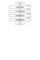
- FIG. 4 is a flowchart illustrating an example of the first vibration information acquisition process according to the first embodiment.
- FIG. 5 is a flowchart illustrating an example of the second vibration information acquisition process according to the first embodiment.
- FIG. 6 is a flowchart illustrating an example of a state determination process according to the first embodiment.
- FIG. 1 is a diagram showing an example of a schematic configuration of a ball screw state determination system.
- FIG. 2 is a block diagram illustrating an example of a ball screw state determination device according to an embodiment.
- FIG. 3A is a conceptual diagram illustrating
- FIG. 7 is a flowchart illustrating an example of a state determination process according to a modification of the first embodiment.
- FIG. 8A is a conceptual diagram illustrating an example of vibration information generated by the vibration information generating unit.
- FIG. 8B is a conceptual diagram showing an example of vibration information generated by the vibration information generating unit.
- FIG. 9 is a flowchart illustrating an example of the first vibration information acquisition process according to the second embodiment.
- FIG. 10 is a conceptual diagram illustrating an example of first vibration information generated by a first vibration information acquisition process according to the second embodiment.
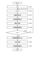
- FIG. 11 is a flowchart illustrating an example of a first vibration information acquisition process according to the third embodiment.
- FIG. 12 is a conceptual diagram illustrating an example of first vibration information generated by a first vibration information acquisition process according to the third embodiment.
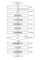
- FIG. 13 is a flowchart illustrating an example of a first vibration information acquisition process according to a modification of the third embodiment.
- FIG. 14 is a conceptual diagram illustrating an example of first vibration information generated by a first vibration information acquisition process according to a modification of the third embodiment.
- FIG. 15 is a flowchart illustrating an example of the second vibration information acquisition process according to the fourth embodiment.
- FIG. 16 is a flowchart illustrating an example of a second vibration information acquisition process according to a modification of the fourth embodiment.
- Figure 1 shows an example of the schematic configuration of a ball screw state determination system.
- the ball screw 1 has a screw shaft 11 and a nut 12 that is fitted onto the screw shaft 11 via multiple rolling elements (not shown) so as to be slidable.
- Both ends of the screw shaft 11 are rotatably supported by bearings 13 and 14, and one end of the screw shaft 11 (the right side in FIG. 1) is connected to the output shaft of a driving motor 15.
- the screw shaft 11 rotates, the nut 12 moves linearly in the axial direction of the screw shaft 11 (the direction of the arrow in FIG. 1) between ends A and B shown in FIG. 1.
- the state determination device 2 of the ball screw 1 determines the state of the ball screw 1 based on a vibration signal acquired while the ball screw 1 is in operation.
- the state determination device 2 outputs a drive control command and a rotation control command for the motor 15 to the drive control device 3.
- the drive control device 3 drives the motor 15 to operate the ball screw 1 and move the nut 12 over the entire area of the screw shaft 11.
- the drive control device 3 outputs the rotational speed of the motor 15, in other words, the rotational speed of the screw shaft 11 of the ball screw 1, to the state determination device 2.
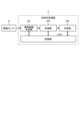
- FIG. 2 is a block diagram showing an example of a state determination device for a ball screw according to an embodiment.
- the state determination device 2 for the ball screw 1 according to the embodiment includes a vibration information generating unit 201, a determination unit 202, a storage unit 203, and a processing unit 204.
- a vibration signal acquired by a vibration sensor 21 during operation of the ball screw 1 is input to the state determination device 2.
- the vibration sensor 21 is installed, for example, on the nut 12 of the ball screw 1 shown in FIG. 1.
- the vibration sensor 21 is exemplified by an acceleration sensor such as an acceleration pickup.
- the direction of acceleration detection by the vibration sensor 21 may be the axial direction of the screw shaft 11 (the direction of the arrow shown in FIG. 1) or a direction perpendicular to the axial direction of the screw shaft 11.
- the installation location of the vibration sensor 21 may be any position that can detect vibrations during operation of the ball screw 1, and is not limited to the nut 12.
- the vibration sensor 21 is not limited to an acceleration sensor.
- the vibration sensor 21 may be, for example, a displacement sensor or a sound pressure sensor such as a microphone.
- the vibration information generating unit 201 generates vibration information indicating the relationship between the nut position of the ball screw and the frequency-vibration level characteristics that change according to the nut position, based on the vibration signal detected by the vibration sensor 21.
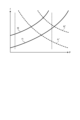
- Figures 3A and 3B are conceptual diagrams showing an example of vibration information generated by the vibration information generating unit.
- the horizontal axis indicates the position P of the nut 12 (hereinafter also simply referred to as the "nut position")
- the vertical axis indicates the frequency f.
- the frequency range of the vibration information is set to a predetermined range, for example, between 10 Hz and 10 kHz.
- the frequency spectrum of the vibration signal acquired during operation of the ball screw 1 has a natural frequency that changes depending on the nut position.
- Figures 3A and 3B show, by way of example, a frequency f1 corresponding to the primary natural frequency in the primary natural mode between nut positions N and A, a frequency f2 corresponding to the secondary natural frequency in the primary natural mode between nut positions N and A, a frequency f1' corresponding to the primary natural frequency in the primary natural mode between nut positions N and B, and a frequency f2' corresponding to the secondary natural frequency in the primary natural mode between nut positions N and B.
- the degree of wear of the ball screw 1 can be determined based on the vibration information generated by the vibration information generating unit 201.
- FIG. 3A illustrates vibration information acquired in a state where a normal preload is applied, for example, immediately after the manufacture of the ball screw 1.
- FIG. 3B illustrates vibration information acquired in a state where a decrease in the preload of the ball screw 1 has occurred due to deformation of the raceway surface accompanying the movement of the rolling elements or wear of the rolling elements.
- the magnitude of the vibration level for each frequency defined by the magnitude of the frequency spectrum is represented by the thickness of the ridge lines that appear in the vibration information, in other words, the lines that indicate the frequency change corresponding to each natural frequency.
- the amount and size of noise components that appear in the vibration information uncorrelated to each natural vibration are represented by the density of the hatching.
- the vibration information shown in Figure 3B shows an example in which the vibration levels of each natural vibration are relatively small and the vibration levels of noise components uncorrelated to each natural vibration are large compared to the vibration information shown in Figure 3A.
- the state determination device 2 of the ball screw 1 determines the degree of wear of the ball screw 1 using the first vibration information acquired in a state in which a normal preload has been applied and the second vibration information acquired when performing the state determination.
- the state determination device 2 of the ball screw 1 first acquires first vibration information during a first period during which the ball screw 1 can be assumed to be in a normally applied preload state (first vibration information acquisition process), and acquires second vibration information during a second period during which the state determination of the ball screw 1 is performed (second vibration information acquisition process). The state determination device 2 then uses the first vibration information acquired during the first period and the second vibration information acquired during the second period to determine the degree of wear of the ball screw 1 (state determination process).
- the object of judgment is a change in state due to damage or wear associated with the operation of the ball screw 1.
- the first period for acquiring the first vibration information is a period during which it is assumed that the normal preload state is maintained, and is set to a period from the start of operation of the ball screw 1 until the passage of approximately 1/10 of the period assumed as the operation period of the ball screw 1. Specifically, for example, it is preferable to set the period to approximately one month in an operation in which the ball screw 1 is replaced every year, and approximately one year in an operation in which the ball screw 1 is replaced every 10 years.
- FIG. 4 is a flowchart illustrating an example of the first vibration information acquisition process according to the first embodiment.
- the state determination device 2 operates the ball screw 1 during a first period during which it is assumed that the ball screw 1 is in a normal preloaded state, and acquires first vibration information. Specifically, in the state determination system for the ball screw 1 shown in FIG. 1, the state determination device 2 outputs a drive control command and a rotation control command for the motor 15 to the drive control device 3. Based on the control command from the state determination device 2, the drive control device 3 drives the motor 15 to operate the ball screw 1.
- the vibration information generating unit 201 acquires a vibration signal that has been converted into digital data by an AD conversion processing unit (not shown) (step S110), and generates first vibration information indicating the relationship between the nut position of the ball screw 1 and the vibration level for each frequency based on the acquired vibration signal (step S120).
- the vibration information generating unit 201 stores the first vibration information generated in step S120 in the storage unit 203 (step S130), and ends the first vibration information acquisition process.
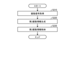
- FIG. 5 is a flowchart showing an example of the second vibration information acquisition process according to the first embodiment.
- the state determination device 2 first operates the ball screw 1 in a second period in which the state of the ball screw 1 is determined after the first period in which the first vibration information was generated, and acquires the second vibration information. Specifically, in the state determination system for the ball screw 1 shown in FIG. 1, the state determination device 2 outputs a drive control command and a rotation control command for the motor 15 to the drive control device 3. Based on the control command from the state determination device 2, the drive control device 3 drives the motor 15 to operate the ball screw 1.
- the second vibration information acquisition process may be executed, for example, when the ball screw 1 is started, or may be executed, for example, at a specified time or every time a specified period of time has elapsed.
- the vibration information generating unit 201 acquires a vibration signal that has been converted into digital data by an AD conversion processing unit (not shown) (step S210), and generates second vibration information indicating the relationship between the nut position of the ball screw 1 and the vibration level for each frequency based on the acquired vibration signal (step S220).
- the vibration information generating unit 201 stores the second vibration information generated in step S220 in the storage unit 203 (step S230), and ends the second vibration information acquisition process.
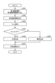
- FIG. 6 is a flowchart showing an example of the state determination process according to the first embodiment.
- the processing unit 204 first reads out the first vibration information and the second vibration information stored in the storage unit 203 (step S301).
- the first vibration information and the second vibration information are information that holds vibration values V(P, f) for each coordinate (P, f) defined by the nut position (P) and frequency (f) of the ball screw 1, as shown in Fig. 3A and Fig. 3B.
- the first vibration information generated based on the vibration signal acquired in the first period assumed to be in a state in which preload is normally applied has a high vibration level at each natural frequency, as shown in Fig. 3A, for example, and the frequency change corresponding to each natural frequency is clearly expressed.
- the second vibration information generated based on the vibration signal acquired in the second period in which the state of the ball screw 1 is determined has a lower vibration level at each natural frequency, as shown in Fig. 3B, for example, and it is assumed that the difference between the vibration level corresponding to each natural frequency and the noise component that appears uncorrelated with each natural frequency is reduced.
- the state determination device 2 determines the degree of wear of the ball screw 1 using the first vibration information acquired in the first period and the second vibration information acquired in the second period.
- the processing unit 204 generates third vibration information by applying the first vibration information to the second vibration information (step S302), and outputs the third vibration information to the determination unit 202. More specifically, the processing unit 204 multiplies the second vibration information by the first vibration information to calculate the third vibration information.
- the processing unit 204 multiplies the vibration values of the corresponding coordinates between the first vibration information and the second vibration information to obtain the vibration value of each coordinate in the third vibration information.
- the vibration value V3(P,f) at the coordinate (P,f) of the third vibration information can be expressed by the following formula (1) where the vibration value at the coordinate (P,f) of the first vibration information is V1(P,f) and the vibration value at the coordinate (P,f) of the second vibration information is V2(P,f).
- V3(P,f) V2(P,f) ⁇ V1(P,f)...(1)
- third vibration information is obtained in which noise components that are uncorrelated with each other between the first vibration information and the second vibration information are relatively reduced for the vibration value of each natural vibration component.
- the determination unit 202 determines the degree of wear of the ball screw 1 using the third vibration information generated by the processing unit 204.
- the determination unit 202 executes a statistical value calculation process on the third vibration information generated by the processing unit 204 (step S303). More specifically, for example, the effective value Vrms of the vibration value at each coordinate of the third vibration information is calculated.
- the determination unit 202 executes a threshold determination process on the statistical value calculated in step S303 to determine the state of the ball screw 1. Specifically, the determination unit 202 determines, for example, whether the effective value Vrms calculated in step S303 is equal to or greater than a pre-stored threshold value Vth (step S304).
- the threshold value Vth is set by simulation as the lower limit of the effective value at which the ball screw 1 is assumed to be normal.
- step S304 If the effective value Vrms statistical value is equal to or greater than the threshold value Vth (Vrms ⁇ Vth, step S304; Yes), the judgment unit 202 judges that the ball screw 1 is normal (step S305), outputs the judgment result (step S307), and ends the state judgment process.
- the judgment unit 202 judges that an abnormality has occurred in the ball screw 1 (step S306), outputs the judgment result (step S307), and ends the state judgment process.
- first vibration information generated based on a vibration signal acquired during a first period during which a normal preload is assumed is held, and third vibration information is generated by applying the first vibration information to second vibration information generated based on a vibration signal acquired during a second period during which the state of the ball screw 1 is determined.
- the processing unit 204 calculates the third vibration information by multiplying the second vibration information by the first vibration information.
- a statistical value calculation process is performed on the generated third vibration information, and the calculated statistical value (e.g., effective value) is used as information indicating the degree of wear of the ball screw 1. This can improve noise resistance and increase the accuracy of determining the degree of wear of the ball screw 1.
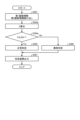
- Modification 7 is a flowchart showing an example of a state determination process according to a modification of the first embodiment.
- the first vibration information acquisition process and the second vibration information acquisition process according to the modification of the first embodiment are similar to those of the first embodiment described above, and therefore detailed description thereof will be omitted here.
- processing different from that of the first embodiment will be described in detail, and detailed description of processing similar to that of the first embodiment may be omitted here.
- the processing unit 204 executes a process of calculating the degree of coincidence S between the first vibration information and the second vibration information read out in step S301 (step S303a) instead of the third vibration information generation process (step S302) and the statistical value calculation process (step S303) shown in FIG. 6.
- the processing unit 204 calculates the degree of agreement (similarity) S between the first vibration information and the second vibration information using a template matching method such as SSD (Sum of Squared Difference) or SAD (Sum of Absolute Difference). More specifically, the processing unit 204 calculates the degree of agreement (similarity) of the second vibration information to the first vibration information by using the first vibration information as a template image and the second vibration information as a search image.
- a template matching method such as SSD (Sum of Squared Difference) or SAD (Sum of Absolute Difference). More specifically, the processing unit 204 calculates the degree of agreement (similarity) of the second vibration information to the first vibration information by using the first vibration information as a template image and the second vibration information as a search image.
- the determination unit 202 determines the degree of wear of the ball screw 1 using the degree of coincidence S calculated by the processing unit 204.
- the determination unit 202 performs a threshold determination process on the degree of coincidence S calculated by the processing unit 204 to determine the state of the ball screw 1.
- FIGS. 8A and 8B are conceptual diagrams showing an example of vibration information generated by the vibration information generating unit.
- FIG. 8A illustrates an example of second vibration information in which the degree of agreement S calculated by the processing unit 204 for the first vibration information acquired in the first period that can be assumed to be in a state in which preload is normally applied is equal to or less than the threshold value Sth.
- FIG. 8B illustrates an example of second vibration information in which the degree of agreement S calculated by the processing unit 204 for the first vibration information acquired in the first period that can be assumed to be in a state in which preload is normally applied is greater than the threshold value Sth.
- the threshold value Sth is set by simulation as the upper limit of the degree of agreement at which the ball screw 1 is assumed to be normal.
- the vibration information includes vibration spectra that correspond to each natural vibration, as well as vibration spectra that are uncorrelated with each natural vibration.
- the vibration spectra that correspond to each natural vibration are also referred to as "stationary continuous spectra.”
- the vibration spectrum components that appear on the dashed lines shown in Figures 8A and 8B are also referred to as “non-stationary continuous spectra.”
- the point-like vibration spectrum components that appear discretely in Figures 8A and 8B are also referred to as “discrete spectra.”
- non-stationary continuous spectra are vibration components that appear regardless of the degree of wear of the ball screw 1.
- the discrete spectrum includes mechanical noise components that occur at production sites, etc., in addition to periodic vibration components that occur as the ball screw 1 is driven.
- step S303a As the preload of the ball screw 1 decreases, the vibration spectrum caused by wear of the ball screw 1 increases, and the degree of match S calculated by the processing unit 204 in step S303a increases.
- the determination unit 202 determines whether the degree of match S calculated in step S303a is equal to or less than a threshold value Sth stored in advance (step S304a).
- the determination unit 202 determines that the ball screw 1 is normal (step S305), outputs the determination result (step S307), and ends the state determination process.
- the judgment unit 202 judges that an abnormality has occurred in the ball screw 1 (step S306), outputs the judgment result (step S307), and ends the state judgment process.
- SSD and SAD are exemplified as template matching methods, but the present invention is not limited to these.
- the degree of match may be calculated using normalized cross-correlation (NCC: Normalized Cross-Correlation, ZNCC: Zero-mean Normalized Cross-Correlation).
- NCC Normalized Cross-Correlation
- ZNCC Zero-mean Normalized Cross-Correlation
- an optimal determination method may be adopted depending on the template matching method of the processing unit 204 in step S303a.
- the degree of agreement (similarity) between the second vibration information and the first vibration information is used as information indicating the degree of wear of the ball screw 1.
- noise resistance can be improved as in the first embodiment, and the accuracy of determining the degree of wear of the ball screw 1 can be improved.
- FIG. 9 is a flowchart showing an example of the first vibration information acquisition process according to the second embodiment.
- the second vibration information acquisition process and the state determination process according to the second embodiment are the same as those of the first embodiment, and therefore detailed description thereof will be omitted here.
- the second embodiment may adopt the state determination process shown in FIG. 6 described in the first embodiment (a process for determining the degree of wear of the ball screw 1 using the statistical value of the third vibration information obtained by multiplying the first vibration information and the second vibration information), or may adopt the state determination process shown in FIG. 7 (a process for determining the degree of wear of the ball screw 1 using the degree of agreement (similarity) of the second vibration information with respect to the first vibration information).
- FIG. 6 a process for determining the degree of wear of the ball screw 1 using the statistical value of the third vibration information obtained by multiplying the first vibration information and the second vibration information
- FIG. 7 a process for determining the degree of wear of the ball screw 1 using the degree of agreement (similarity) of the second vibration information with respect to the first
- the vibration information generating unit 201 executes a process of removing noise components from the vibration signal acquired in step S110 (step S111).
- the vibration information generating unit 201 removes periodic vibration components of the vibration signal as noise components, for example, by using Cepstrum Pre-Whitening (CPW) processing or Cepstrum Editing Process (CEP processing) including CPW.
- CPW Cepstrum Pre-Whitening
- CEP processing Cepstrum Editing Process
- the vibration information generating unit 201 generates first vibration information based on the vibration signal after the noise components have been removed (step S120a), stores the first vibration information in the storage unit 203 (step S130), and ends the first vibration information acquisition process.
- FIG. 10 is a conceptual diagram showing an example of first vibration information generated by the first vibration information acquisition process according to the second embodiment.
- a noise component removal process step S111
- the first vibration information from which the discrete spectrum described in FIGS. 8A and 8B has been removed is obtained, as shown in FIG. 10. This makes it possible to improve noise resistance compared to the first embodiment, and to increase the accuracy of determining the degree of wear of the ball screw 1.
- FIG. 11 is a flowchart showing an example of the first vibration information acquisition process according to the third embodiment.
- the second vibration information acquisition process and the state determination process according to the third embodiment are the same as those of the first embodiment, and therefore detailed description thereof will be omitted here.
- the third embodiment may adopt the state determination process shown in FIG. 6 described in the first embodiment (a process for determining the degree of wear of the ball screw 1 using the statistical value of the third vibration information obtained by multiplying the first vibration information and the second vibration information), or may adopt the state determination process shown in FIG. 7 (a process for determining the degree of wear of the ball screw 1 using the degree of agreement (similarity) of the second vibration information with respect to the first vibration information).
- FIG. 6 a process for determining the degree of wear of the ball screw 1 using the statistical value of the third vibration information obtained by multiplying the first vibration information and the second vibration information
- FIG. 7 a process for determining the degree of wear of the ball screw 1 using the degree of agreement (similarity) of the second vibration information with respect to the first
- the first vibration information is acquired 10 or more times (N ⁇ 10) during the first period until about 1/10 of the period assumed to be the operation period of the ball screw 1 has elapsed.
- the vibration information generating unit 201 acquires the vibration signal that has been converted into digital data by an AD conversion processing unit (not shown) (step S110), and generates first vibration information indicating the relationship between the nut position of the ball screw 1 and the vibration level for each frequency based on the acquired vibration signal (step S120).
- the vibration information generating unit 201 performs a normalization process on the first vibration information generated in step S120 (step S123).
- the vibration information generating unit 201 executes a standardization process on the first vibration information generated in step S120. More specifically, the vibration information generating unit 201 scales the average of the first vibration information to "0" and the standard deviation (or variance) to "1.”
- the vibration information generating unit 201 may perform a normalization process on the first vibration information generated in step S120 instead of the standardization process. More specifically, the vibration information generating unit 201 may scale the minimum of the first vibration information to "-1" (or "0") and the maximum to "1".
- the processing from step S110 onwards may be performed, for example, when the ball screw 1 is started, or may be performed, for example, at a specified time or every time a specified period of time has elapsed. It is desirable that the interval at which the processing from step S110 onwards is performed is set so that step S131 is satisfied within a first period defined as the period for acquiring the first vibration information. Alternatively, if the first period has elapsed before step S131 is satisfied, it is desirable that the first period is extended until the number of times n that the first vibration information is acquired becomes N.
- the vibration information generating unit 201 After acquiring the N pieces of first vibration information, the vibration information generating unit 201 reads out the N pieces of first vibration information stored in the storage unit 203 (step S132), and performs an averaging process on the read out N pieces of first vibration information (step S133). More specifically, the vibration information generating unit 201 calculates the average value of the vibration values of the corresponding coordinates among the N pieces of first vibration information.
- FIG. 12 is a conceptual diagram showing an example of first vibration information generated by the first vibration information acquisition process according to the third embodiment.
- FIG. 13 is a flowchart showing an example of a first vibration information acquisition process according to a modified example of the third embodiment.
- Fig. 14 is a conceptual diagram showing an example of first vibration information generated by a first vibration information acquisition process according to a modified example of the third embodiment. Note that the second vibration information acquisition process and the state determination process according to the modified example of the third embodiment are similar to those of the third embodiment described above, and therefore detailed descriptions thereof will be omitted here. Also, here, processes different from those of the third embodiment will be described in detail, and detailed descriptions of processes similar to those of the third embodiment may be omitted.
- the first vibration information acquisition process according to the modified example of the third embodiment is combined with the noise component removal process (step S111) of the second embodiment.
- the noise component removal process step S111
- the first vibration information is obtained from which the discrete spectrum and non-stationary continuous spectrum described in FIG. 8A and FIG. 8B have been removed. This makes it possible to further improve noise resistance compared to the second and third embodiments, and to increase the accuracy of determining the degree of wear of the ball screw 1.
- FIG. 15 is a flowchart showing an example of the second vibration information acquisition process according to the fourth embodiment.
- the first vibration information acquisition process and the state determination process according to the fourth embodiment are the same as those of the third embodiment, and therefore detailed description thereof will be omitted here.
- the fourth embodiment may adopt the state determination process shown in FIG. 6 described in the first embodiment (a process for determining the degree of wear of the ball screw 1 using the statistical value of the third vibration information obtained by multiplying the first vibration information and the second vibration information), or may adopt the state determination process shown in FIG. 7 (a process for determining the degree of wear of the ball screw 1 using the degree of agreement (similarity) of the second vibration information with respect to the first vibration information).
- FIG. 7 a process for determining the degree of wear of the ball screw 1 using the degree of agreement (similarity) of the second vibration information with respect to the first vibration information.
- the number M of times the second vibration information is acquired in the second period is, for example, the same as the number N of times the first vibration information is acquired. Specifically, the second vibration information is acquired, for example, 10 times or more in the second period (M ⁇ 10).
- the vibration information generating unit 201 acquires the vibration signal that has been converted into digital data by an AD conversion processing unit (not shown) (step S210), and generates second vibration information indicating the relationship between the nut position of the ball screw 1 and the vibration level for each frequency based on the acquired vibration signal (step S220).
- the vibration information generating unit 201 performs a normalization process on the second vibration information generated in step S220 (step S223).
- the vibration information generating unit 201 performs a standardization process on the second vibration information generated in step S220. More specifically, the vibration information generating unit 201 scales the average of the second vibration information to "0" and the standard deviation (or variance) to "1.”
- the vibration information generating unit 201 may perform a normalization process on the first vibration information generated in step S220 instead of the standardization process. More specifically, the vibration information generating unit 201 may scale the minimum of the second vibration information to "-1" (or "0") and the maximum to "1".
- the method of standardizing the second vibration information in the second vibration information acquisition process according to the fourth embodiment is preferably the same as the method of standardizing the first vibration information.
- the first vibration information acquisition process (step S123 in FIG. 11 or FIG. 13) is performed as a standardization process for the first vibration information
- the second vibration information acquisition process (step S223) is also similarly performed as a standardization process for the second vibration information.
- the first vibration information acquisition process (step S123 in FIG. 11 or FIG. 13) is performed as a normalization process for the first vibration information
- the second vibration information acquisition process (step S223) is also similarly performed as a normalization process for the second vibration information.
- the vibration information generating unit 201 After acquiring the M pieces of second vibration information, the vibration information generating unit 201 reads out the M pieces of second vibration information stored in the storage unit 203 (step S232), and performs an averaging process on the M pieces of second vibration information that have been read out (step S233). More specifically, the vibration information generating unit 201 calculates the average value of the vibration values of the corresponding coordinates between the M pieces of second vibration information.
- Modification 16 is a flowchart showing an example of a second vibration information acquisition process according to a modification of the fourth embodiment.
- the first vibration information acquisition process and the state determination process according to the fourth embodiment are similar to those of the fourth embodiment described above, and therefore detailed descriptions thereof will be omitted here.
- processes different from the second vibration information acquisition process according to the fourth embodiment will be described in detail, and detailed descriptions of processes similar to those of the fourth embodiment may be omitted.
- a noise component removal process similar to the noise component removal process (step S111) for the first vibration information in embodiment 2 is combined with the second vibration information acquisition process according to embodiment 4 described above.
- the discrete spectrum and non-stationary continuous spectrum described in FIG. 8A and FIG. 8B are removed, and more accurate second vibration information is obtained. This makes it possible to further improve noise resistance compared to embodiment 4, and further increase the accuracy of determining the degree of wear of the ball screw 1.
- the state determination device 2 and state determination method for the ball screw 1 can improve noise resistance and increase the accuracy of determining the degree of wear of the ball screw 1.
- the vibration information may be binary information, for example, with vibration values equal to or greater than a predetermined value being "1" and vibration values less than the predetermined value being "0.”
Landscapes
- Physics & Mathematics (AREA)
- Engineering & Computer Science (AREA)
- General Engineering & Computer Science (AREA)
- Acoustics & Sound (AREA)
- General Physics & Mathematics (AREA)
- Mechanical Engineering (AREA)
- Testing Of Devices, Machine Parts, Or Other Structures Thereof (AREA)
- Transmission Devices (AREA)
Abstract
Description
図4は、実施形態1に係る第1振動情報取得処理の一例を示すフローチャートである。
図7は、実施形態1の変形例に係る状態判定処理の一例を示すフローチャートである。なお、実施形態1の変形例に係る第1振動情報取得処理及び第2振動情報取得処理は、上述した実施形態1と同様であるので、ここでの詳細な説明は省略する。また、ここでは、実施形態1とは異なる処理について詳細に説明し、実施形態1と同様の処理については詳細な説明を省略する場合がある。
図9は、実施形態2に係る第1振動情報取得処理の一例を示すフローチャートである。なお、実施形態2に係る第2振動情報取得処理及び状態判定処理は、上述した実施形態1と同様であるので、ここでの詳細な説明は省略する。具体的に、実施形態2では、実施形態1において説明した図6に示す状態判定処理(第1振動情報と第2振動情報とを掛け合わせた第3振動情報の統計値を用いてボールねじ1の損耗度合いを判定する処理)を採用する態様であっても良いし、図7に示す状態判定処理(第1振動情報に対する第2振動情報の一致度(類似度)を用いてボールねじ1の損耗度合いを判定する処理)を採用する態様であっても良い。また、ここでは、実施形態1とは異なる処理について詳細に説明し、実施形態1と同様の処理については詳細な説明を省略する場合がある。
図11は、実施形態3に係る第1振動情報取得処理の一例を示すフローチャートである。なお、実施形態3に係る第2振動情報取得処理及び状態判定処理は、上述した実施形態1と同様であるので、ここでの詳細な説明は省略する。具体的に、実施形態3では、実施形態1において説明した図6に示す状態判定処理(第1振動情報と第2振動情報とを掛け合わせた第3振動情報の統計値を用いてボールねじ1の損耗度合いを判定する処理)を採用する態様であっても良いし、図7に示す状態判定処理(第1振動情報に対する第2振動情報の一致度(類似度)を用いてボールねじ1の損耗度合いを判定する処理)を採用する態様であっても良い。また、ここでは、実施形態1とは異なる処理について詳細に説明し、実施形態1と同様の処理については詳細な説明を省略する場合がある。
図13は、実施形態3の変形例に係る第1振動情報取得処理の一例を示すフローチャートである。図14は、実施形態3の変形例に係る第1振動情報取得処理により生成される第1振動情報の一例を示す概念図である。なお、実施形態3の変形例に係る第2振動情報取得処理及び状態判定処理は、上述した実施形態3と同様であるので、ここでの詳細な説明は省略する。また、ここでは、実施形態3とは異なる処理について詳細に説明し、実施形態3と同様の処理については詳細な説明を省略する場合がある。
図15は、実施形態4に係る第2振動情報取得処理の一例を示すフローチャートである。なお、実施形態4に係る第1振動情報取得処理及び状態判定処理は、実施形態3と同様であるので、ここでの詳細な説明は省略する。具体的に、実施形態4では、実施形態1において説明した図6に示す状態判定処理(第1振動情報と第2振動情報とを掛け合わせた第3振動情報の統計値を用いてボールねじ1の損耗度合いを判定する処理)を採用する態様であっても良いし、図7に示す状態判定処理(第1振動情報に対する第2振動情報の一致度(類似度)を用いてボールねじ1の損耗度合いを判定する処理)を採用する態様であっても良い。また、ここでは、実施形態3とは異なる処理について詳細に説明し、実施形態3と同様の処理については詳細な説明を省略する場合がある。
図16は、実施形態4の変形例に係る第2振動情報取得処理の一例を示すフローチャートである。なお、実施形態4の変形例に係る第1振動情報取得処理及び状態判定処理は、上述した実施形態4と同様であるので、ここでの詳細な説明は省略する。また、ここでは、実施形態4に係る第2振動情報取得処理とは異なる処理について詳細に説明し、実施形態4と同様の処理については詳細な説明を省略する場合がある。
2 状態判定装置
3 駆動制御装置
11 ねじ軸
12 ナット
13,14 軸受
15 モータ
21 振動センサ
201 振動情報生成部
202 判定部
203 記憶部
204 処理部
Claims (20)
- ボールねじの作動時において振動センサにより取得された振動信号に基づき、前記ボールねじのナット位置と、当該ナット位置に応じて変化する周波数-振動レベル特性との関係を示す振動情報を生成する振動情報生成部と、
第1期間において取得した振動信号に基づき生成される第1振動情報、及び、前記第1期間よりも後の第2期間において取得した第2振動情報に基づき、前記ボールねじの状態判定処理を実行する判定部と、
を備える、
ボールねじの状態判定装置。 - 前記振動情報生成部は、
前記第1期間において取得した複数の第1振動情報の平均化処理を実行する、
請求項1に記載のボールねじの状態判定装置。 - 前記振動情報生成部は、
前記第1期間において取得した振動信号の周期的振動成分を除去した第1振動情報を生成する、
請求項1に記載のボールねじの状態判定装置。 - 前記振動情報生成部は、
前記第1期間において取得した複数の第1振動情報の平均化処理を実行する、
請求項3に記載のボールねじの状態判定装置。 - 前記振動情報生成部は、
前記第2期間において取得した複数の第2振動情報の平均化処理を実行する、
請求項4に記載のボールねじの状態判定装置。 - 前記振動情報生成部は、
前記第2期間において取得した振動信号の周期的振動成分を除去した第2振動情報を生成する、
請求項5に記載のボールねじの状態判定装置。 - 前記第2振動情報に前記第1振動情報を乗じた第3振動情報を算出する処理部をさらに備える、
請求項1から6の何れか一項に記載のボールねじの状態判定装置。 - 前記判定部は、
前記第3振動情報の統計値に基づき、前記ボールねじの損耗度合いを判定する、
請求項7に記載のボールねじの状態判定装置。 - 前記第1振動情報に対する前記第2振動情報の一致度を算出する処理部をさらに備える、
請求項1から6の何れか一項に記載のボールねじの状態判定装置。 - 前記判定部は、
前記一致度に基づき、前記ボールねじの損耗度合いを判定する、
請求項9に記載のボールねじの状態判定装置。 - 第1期間において、ボールねじの作動時に取得された振動信号に基づき、前記ボールねじのナット位置と、当該ナット位置に応じて変化する周波数-振動レベル特性との関係を示す第1振動情報を生成する第1ステップと、
前記第1期間よりも後の第2期間において、前記ボールねじの作動時に取得された振動信号に基づき、前記ボールねじのナット位置と、当該ナット位置に応じて変化する周波数-振動レベル特性との関係を示す第2振動情報を生成する第2ステップと、
前記第1振動情報及び前記第2振動情報に基づき、前記ボールねじの状態判定処理を実行する第3ステップと、
を有する、
ボールねじの状態判定方法。 - 前記第1ステップにおいて、
前記第1期間において取得した複数の第1振動情報の平均化処理を実行する、
請求項11に記載のボールねじの状態判定方法。 - 前記第1ステップにおいて、
前記第1期間において取得した振動信号の周期的振動成分を除去した第1振動情報を生成する、
請求項11に記載のボールねじの状態判定方法。 - 前記第1ステップにおいて、
前記第1期間において取得した複数の第1振動情報の平均化処理を実行する、
請求項13に記載のボールねじの状態判定方法。 - 前記第2ステップにおいて、
前記第2期間において取得した複数の第2振動情報の平均化処理を実行する、
請求項14に記載のボールねじの状態判定方法。 - 前記第2ステップにおいて、
前記第2期間において取得した振動信号の周期的振動成分を除去した第2振動情報を生成する、
請求項15に記載のボールねじの状態判定方法。 - 前記第3ステップにおいて、
前記第2振動情報に前記第1振動情報を乗じた第3振動情報を算出する、
請求項11から16の何れか一項に記載のボールねじの状態判定方法。 - 前記第3ステップにおいて、
前記第3振動情報の統計値に基づき、前記ボールねじの損耗度合いを判定する、
請求項17に記載のボールねじの状態判定方法。 - 前記第3ステップにおいて、
前記第1振動情報に対する前記第2振動情報の一致度を算出する、
請求項11から16の何れか一項に記載のボールねじの状態判定方法。 - 前記第3ステップにおいて、
前記一致度に基づき、前記ボールねじの損耗度合いを判定する、
請求項19に記載のボールねじの状態判定方法。
Priority Applications (2)
| Application Number | Priority Date | Filing Date | Title |
|---|---|---|---|
| EP24747969.4A EP4726351A1 (en) | 2023-06-06 | 2024-01-15 | State determination device and state determination method for ball screw |
| CN202480001593.5A CN119452236A (zh) | 2023-06-06 | 2024-01-15 | 滚珠丝杠的状态判定装置和状态判定方法 |
Applications Claiming Priority (2)
| Application Number | Priority Date | Filing Date | Title |
|---|---|---|---|
| JP2023093206A JP2024175424A (ja) | 2023-06-06 | 2023-06-06 | ボールねじの状態判定装置及び状態判定方法 |
| JP2023-093206 | 2023-06-06 |
Publications (1)
| Publication Number | Publication Date |
|---|---|
| WO2024252713A1 true WO2024252713A1 (ja) | 2024-12-12 |
Family
ID=93795194
Family Applications (1)
| Application Number | Title | Priority Date | Filing Date |
|---|---|---|---|
| PCT/JP2024/000793 Ceased WO2024252713A1 (ja) | 2023-06-06 | 2024-01-15 | ボールねじの状態判定装置及び状態判定方法 |
Country Status (4)
| Country | Link |
|---|---|
| EP (1) | EP4726351A1 (ja) |
| JP (1) | JP2024175424A (ja) |
| CN (1) | CN119452236A (ja) |
| WO (1) | WO2024252713A1 (ja) |
Cited By (1)
| Publication number | Priority date | Publication date | Assignee | Title |
|---|---|---|---|---|
| CN119673506A (zh) * | 2024-12-19 | 2025-03-21 | 中国核动力研究设计院 | 滚轮丝杠控制棒驱动机构状态在线监测方法、系统及介质 |
Citations (9)
| Publication number | Priority date | Publication date | Assignee | Title |
|---|---|---|---|---|
| JP2007285874A (ja) * | 2006-04-17 | 2007-11-01 | Nsk Ltd | 異常診断装置及び異常診断方法 |
| JP2009198398A (ja) | 2008-02-22 | 2009-09-03 | Nsk Ltd | 転がり直動装置の作動状態検査方法および作動状態検査装置 |
| JP2013257253A (ja) * | 2012-06-14 | 2013-12-26 | Nsk Ltd | ボールねじ装置の異常検出装置及び異常検出方法 |
| US20150147007A1 (en) * | 2010-05-27 | 2015-05-28 | Hiwin Technologies Corp. | Bearing failure monitoring device for ball screw |
| JP2016031307A (ja) * | 2014-07-29 | 2016-03-07 | Jfeアドバンテック株式会社 | 信号処理方法及び信号処理装置 |
| JP2019105317A (ja) * | 2017-12-13 | 2019-06-27 | Thk株式会社 | ボールねじユニットの診断システムおよびモータ制御システム |
| JP2019168412A (ja) * | 2018-03-26 | 2019-10-03 | Ntn株式会社 | 異常検出装置および異常検出方法 |
| CN110781612A (zh) * | 2019-11-14 | 2020-02-11 | 哈工大机器人(山东)智能装备研究院 | 滚珠丝杠的故障诊断方法、装置、计算机设备和存储介质 |
| WO2020090479A1 (ja) | 2018-10-29 | 2020-05-07 | 日本精工株式会社 | ボールねじの予圧低下検出方法及び直動駆動装置 |
-
2023
- 2023-06-06 JP JP2023093206A patent/JP2024175424A/ja active Pending
-
2024
- 2024-01-15 CN CN202480001593.5A patent/CN119452236A/zh active Pending
- 2024-01-15 WO PCT/JP2024/000793 patent/WO2024252713A1/ja not_active Ceased
- 2024-01-15 EP EP24747969.4A patent/EP4726351A1/en active Pending
Patent Citations (9)
| Publication number | Priority date | Publication date | Assignee | Title |
|---|---|---|---|---|
| JP2007285874A (ja) * | 2006-04-17 | 2007-11-01 | Nsk Ltd | 異常診断装置及び異常診断方法 |
| JP2009198398A (ja) | 2008-02-22 | 2009-09-03 | Nsk Ltd | 転がり直動装置の作動状態検査方法および作動状態検査装置 |
| US20150147007A1 (en) * | 2010-05-27 | 2015-05-28 | Hiwin Technologies Corp. | Bearing failure monitoring device for ball screw |
| JP2013257253A (ja) * | 2012-06-14 | 2013-12-26 | Nsk Ltd | ボールねじ装置の異常検出装置及び異常検出方法 |
| JP2016031307A (ja) * | 2014-07-29 | 2016-03-07 | Jfeアドバンテック株式会社 | 信号処理方法及び信号処理装置 |
| JP2019105317A (ja) * | 2017-12-13 | 2019-06-27 | Thk株式会社 | ボールねじユニットの診断システムおよびモータ制御システム |
| JP2019168412A (ja) * | 2018-03-26 | 2019-10-03 | Ntn株式会社 | 異常検出装置および異常検出方法 |
| WO2020090479A1 (ja) | 2018-10-29 | 2020-05-07 | 日本精工株式会社 | ボールねじの予圧低下検出方法及び直動駆動装置 |
| CN110781612A (zh) * | 2019-11-14 | 2020-02-11 | 哈工大机器人(山东)智能装备研究院 | 滚珠丝杠的故障诊断方法、装置、计算机设备和存储介质 |
Cited By (1)
| Publication number | Priority date | Publication date | Assignee | Title |
|---|---|---|---|---|
| CN119673506A (zh) * | 2024-12-19 | 2025-03-21 | 中国核动力研究设计院 | 滚轮丝杠控制棒驱动机构状态在线监测方法、系统及介质 |
Also Published As
| Publication number | Publication date |
|---|---|
| EP4726351A1 (en) | 2026-04-15 |
| JP2024175424A (ja) | 2024-12-18 |
| CN119452236A (zh) | 2025-02-14 |
Similar Documents
| Publication | Publication Date | Title |
|---|---|---|
| JP2022103461A (ja) | 診断装置、診断方法、プログラムおよび診断システム | |
| JP2017173321A (ja) | 状態監視システムおよび風力発電装置 | |
| Hiruta et al. | Unsupervised learning based diagnosis model for anomaly detection of motor bearing with current data | |
| Singh et al. | Discrete wavelet transform based measurement of inner race defect width in taper roller bearing | |
| WO2018008708A1 (ja) | 震央距離推定装置、震央距離推定方法、及びコンピュータ読み取り可能な記録媒体 | |
| JP6822294B2 (ja) | 評価プログラム、情報処理装置、及び評価方法 | |
| JP2024175424A (ja) | ボールねじの状態判定装置及び状態判定方法 | |
| JP2019168412A (ja) | 異常検出装置および異常検出方法 | |
| CN112740004A (zh) | 滚珠丝杠的预压降低检测方法和直动驱动装置 | |
| WO2024201970A1 (ja) | モータの異常判定装置および異常判定システム | |
| Attoui et al. | Novel machinery monitoring strategy based on time–frequency domain similarity measurement with limited labeled data | |
| CN111159846A (zh) | 基于分数levy稳定运动的滚动轴承剩余有效寿命预测方法 | |
| CN119557766A (zh) | 一种基于ds证据理论的多源数据融合故障诊断方法与系统 | |
| JP7238984B2 (ja) | 振動計測装置、振動計測方法、及びプログラム | |
| JP6330472B2 (ja) | 欠陥検出方法及び欠陥検出システム | |
| US20200073375A1 (en) | Apparatus, method, and computer-readable, non-transitory medium | |
| CN120800819A (zh) | 一种远程诊断牵引车的动力系统故障的方法及系统 | |
| CN119779679A (zh) | 一种轴承故障诊断方法及系统 | |
| JP7349339B2 (ja) | 振動機械の異常診断装置、および、異常診断方法 | |
| US20260043712A1 (en) | Monitoring device and monitoring method | |
| CN117218097B (zh) | 一种轴套类丝网垫圈零件表面缺陷检测方法及装置 | |
| CN117710375A (zh) | 一种电机转子与定子的对中性检测方法及系统 | |
| JP4753654B2 (ja) | 転がり軸受部品の評価法 | |
| CN113994088B (zh) | 用于对风涡轮机的部件进行计算机实现的监测的方法 | |
| CN116539309A (zh) | 一种轴承监测方法、装置及系统 |
Legal Events
| Date | Code | Title | Description |
|---|---|---|---|
| WWE | Wipo information: entry into national phase |
Ref document number: 202480001593.5 Country of ref document: CN |
|
| 121 | Ep: the epo has been informed by wipo that ep was designated in this application |
Ref document number: 24747969 Country of ref document: EP Kind code of ref document: A1 |
|
| WWP | Wipo information: published in national office |
Ref document number: 202480001593.5 Country of ref document: CN |
|
| WWE | Wipo information: entry into national phase |
Ref document number: 2024747969 Country of ref document: EP |
|
| NENP | Non-entry into the national phase |
Ref country code: DE |
|
| ENP | Entry into the national phase |
Ref document number: 2024747969 Country of ref document: EP Effective date: 20260107 |
|
| ENP | Entry into the national phase |
Ref document number: 2024747969 Country of ref document: EP Effective date: 20260107 |
|
| ENP | Entry into the national phase |
Ref document number: 2024747969 Country of ref document: EP Effective date: 20260107 |
|
| ENP | Entry into the national phase |
Ref document number: 2024747969 Country of ref document: EP Effective date: 20260107 |
|
| ENP | Entry into the national phase |
Ref document number: 2024747969 Country of ref document: EP Effective date: 20260107 |