WO2024252623A1 - 浴室暖房乾燥換気システム - Google Patents
浴室暖房乾燥換気システム Download PDFInfo
- Publication number
- WO2024252623A1 WO2024252623A1 PCT/JP2023/021376 JP2023021376W WO2024252623A1 WO 2024252623 A1 WO2024252623 A1 WO 2024252623A1 JP 2023021376 W JP2023021376 W JP 2023021376W WO 2024252623 A1 WO2024252623 A1 WO 2024252623A1
- Authority
- WO
- WIPO (PCT)
- Prior art keywords
- drying
- bathroom
- heating
- ventilation
- main body
- Prior art date
- Legal status (The legal status is an assumption and is not a legal conclusion. Google has not performed a legal analysis and makes no representation as to the accuracy of the status listed.)
- Ceased
Links
Images











Classifications
-
- F—MECHANICAL ENGINEERING; LIGHTING; HEATING; WEAPONS; BLASTING
- F24—HEATING; RANGES; VENTILATING
- F24D—DOMESTIC- OR SPACE-HEATING SYSTEMS, e.g. CENTRAL HEATING SYSTEMS; DOMESTIC HOT-WATER SUPPLY SYSTEMS; ELEMENTS OR COMPONENTS THEREFOR
- F24D15/00—Other domestic- or space-heating systems
-
- F—MECHANICAL ENGINEERING; LIGHTING; HEATING; WEAPONS; BLASTING
- F24—HEATING; RANGES; VENTILATING
- F24F—AIR-CONDITIONING; AIR-HUMIDIFICATION; VENTILATION; USE OF AIR CURRENTS FOR SCREENING
- F24F7/00—Ventilation
- F24F7/007—Ventilation with forced flow
-
- F—MECHANICAL ENGINEERING; LIGHTING; HEATING; WEAPONS; BLASTING
- F24—HEATING; RANGES; VENTILATING
- F24H—FLUID HEATERS, e.g. WATER OR AIR HEATERS, HAVING HEAT-GENERATING MEANS, e.g. HEAT PUMPS, IN GENERAL
- F24H15/00—Control of fluid heaters
- F24H15/20—Control of fluid heaters characterised by control inputs
- F24H15/281—Input from user
-
- F—MECHANICAL ENGINEERING; LIGHTING; HEATING; WEAPONS; BLASTING
- F24—HEATING; RANGES; VENTILATING
- F24H—FLUID HEATERS, e.g. WATER OR AIR HEATERS, HAVING HEAT-GENERATING MEANS, e.g. HEAT PUMPS, IN GENERAL
- F24H15/00—Control of fluid heaters
- F24H15/30—Control of fluid heaters characterised by control outputs; characterised by the components to be controlled
- F24H15/33—Control of dampers
-
- F—MECHANICAL ENGINEERING; LIGHTING; HEATING; WEAPONS; BLASTING
- F24—HEATING; RANGES; VENTILATING
- F24H—FLUID HEATERS, e.g. WATER OR AIR HEATERS, HAVING HEAT-GENERATING MEANS, e.g. HEAT PUMPS, IN GENERAL
- F24H15/00—Control of fluid heaters
- F24H15/30—Control of fluid heaters characterised by control outputs; characterised by the components to be controlled
- F24H15/395—Information to users, e.g. alarms
-
- F—MECHANICAL ENGINEERING; LIGHTING; HEATING; WEAPONS; BLASTING
- F24—HEATING; RANGES; VENTILATING
- F24H—FLUID HEATERS, e.g. WATER OR AIR HEATERS, HAVING HEAT-GENERATING MEANS, e.g. HEAT PUMPS, IN GENERAL
- F24H15/00—Control of fluid heaters
- F24H15/40—Control of fluid heaters characterised by the type of controllers
- F24H15/414—Control of fluid heaters characterised by the type of controllers using electronic processing, e.g. computer-based
- F24H15/421—Control of fluid heaters characterised by the type of controllers using electronic processing, e.g. computer-based using pre-stored data
- F24H15/429—Control of fluid heaters characterised by the type of controllers using electronic processing, e.g. computer-based using pre-stored data for selecting operation modes
-
- F—MECHANICAL ENGINEERING; LIGHTING; HEATING; WEAPONS; BLASTING
- F24—HEATING; RANGES; VENTILATING
- F24H—FLUID HEATERS, e.g. WATER OR AIR HEATERS, HAVING HEAT-GENERATING MEANS, e.g. HEAT PUMPS, IN GENERAL
- F24H15/00—Control of fluid heaters
- F24H15/40—Control of fluid heaters characterised by the type of controllers
- F24H15/414—Control of fluid heaters characterised by the type of controllers using electronic processing, e.g. computer-based
- F24H15/45—Control of fluid heaters characterised by the type of controllers using electronic processing, e.g. computer-based remotely accessible
-
- F—MECHANICAL ENGINEERING; LIGHTING; HEATING; WEAPONS; BLASTING
- F24—HEATING; RANGES; VENTILATING
- F24H—FLUID HEATERS, e.g. WATER OR AIR HEATERS, HAVING HEAT-GENERATING MEANS, e.g. HEAT PUMPS, IN GENERAL
- F24H15/00—Control of fluid heaters
- F24H15/40—Control of fluid heaters characterised by the type of controllers
- F24H15/414—Control of fluid heaters characterised by the type of controllers using electronic processing, e.g. computer-based
- F24H15/45—Control of fluid heaters characterised by the type of controllers using electronic processing, e.g. computer-based remotely accessible
- F24H15/457—Control of fluid heaters characterised by the type of controllers using electronic processing, e.g. computer-based remotely accessible using telephone networks or Internet communication
-
- F—MECHANICAL ENGINEERING; LIGHTING; HEATING; WEAPONS; BLASTING
- F24—HEATING; RANGES; VENTILATING
- F24F—AIR-CONDITIONING; AIR-HUMIDIFICATION; VENTILATION; USE OF AIR CURRENTS FOR SCREENING
- F24F2110/00—Control inputs relating to air properties
- F24F2110/50—Air quality properties
- F24F2110/65—Concentration of specific substances or contaminants
Definitions
- This disclosure relates to a bathroom heating, drying and ventilation system that can be remotely controlled using a remote control terminal.
- Patent Document 1 describes a bathroom dryer system that allows a bathroom dryer to be operated from a mobile terminal and has a function that allows wireless operation to be enabled or disabled from an operating unit installed near the bathroom to prevent unpleasant operation while using the bathroom.
- the bathroom drying system in Patent Document 1 has a function that does not accept operation instructions from a mobile device, but providing this function in the operation unit uses lamps and operation space, which may reduce the functions that the user needs in the operation unit.
- the present disclosure has been made in consideration of the above, and aims to provide a bathroom heating, drying and ventilation system that can be remotely controlled from a remote control terminal other than the control device and in which the functions that the user wants to operate are provided on the control device.
- the bathroom heating, drying and ventilation system disclosed herein comprises a main body unit that circulates air taken in from the bathroom back to the bathroom and expels the air taken in from the bathroom outside the bathroom, an operation device that is installed indoors in the same room as the bathroom and accepts operations on the main body unit, and a remote control terminal that is used indoors or outdoors and accepts external operations that are operations on the main body unit.
- the main body unit is capable of operating in accordance with external operations from the remote control terminal by receiving instructions from the remote control terminal.
- the operation device has some of the remote control functions that remotely control the main body unit possessed by the remote control terminal.
- the present disclosure has the effect of providing a bathroom heating, drying and ventilation system that can be remotely controlled from a remote control terminal other than the control device and in which the functions that the user desires to operate are provided on the control device.
- FIG. 1 is a diagram showing a configuration example of a bathroom heating, drying and ventilation system including a bathroom heating, drying and ventilation device according to a first embodiment.
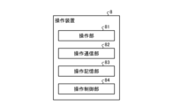
- FIG. 1 is a diagram showing a functional configuration of an operating device of a bathroom heating, drying and ventilation system according to a first embodiment.
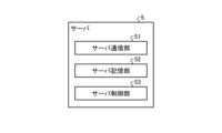
- FIG. 1 is a diagram showing a functional configuration of a server of a bathroom heating, drying and ventilation system according to a first embodiment.
- FIG. 1 is a diagram showing a functional configuration of a remote control terminal of a bathroom heating, drying and ventilation system according to a first embodiment.
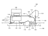
- FIG. 1 is a schematic diagram showing an example of the structure of a bathroom dryer according to a first embodiment; FIG.
- FIG. 1 is a diagram showing a functional configuration of a control unit in a bathroom dryer of a bathroom heating, drying and ventilation system according to a first embodiment.
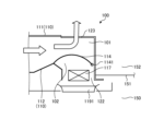
- FIG. 1 is a diagram showing an example of an air path state during ventilation operation of the bathroom dryer according to the first embodiment.
- FIG. 1 is a diagram showing an example of a state of an air passage during heating operation of a bathroom dryer according to a first embodiment.
- FIG. 1 is a diagram showing an example of a state of an air passage during a drying operation of a bathroom dryer according to a first embodiment.
- FIG. 1 is a diagram showing an operating device of a bathroom heating, drying and ventilating apparatus according to a first embodiment.
- FIG. 1 is a sequence diagram for explaining the operation procedure of the bathroom dryer and the operating device when the bathroom dryer according to the first embodiment is operated to perform a heating operation from the operating device;
- FIG. 11 is a sequence diagram for explaining the operation procedure of the bathroom dryer, the server, and the remote control terminal when the bathroom dryer according to the first embodiment is operated in a heating mode from the remote control terminal.
- FIG. 13 is a diagram showing an example of an operation screen displayed on a terminal display unit of a remote control terminal when operating the bathroom dryer according to the first embodiment;
- FIG. 1 is a sequence diagram for explaining the operation procedure of the bathroom dryer and the operating device when the bathroom dryer according to the first embodiment is operated to perform a heating operation from the operating device
- FIG. 11 is a sequence diagram for explaining the operation procedure of the bathroom dryer, the server, and the remote control terminal when the bathroom dryer according to the first embodiment is operated in a heating mode from the
- FIG. 13 is a diagram showing an example of a drying operation setting screen displayed on a terminal display unit of a remote control terminal when remotely controlling the bathroom dryer according to the first embodiment.
- FIG. 13 is a diagram showing an example of a warning screen displayed on a terminal display unit of a remote control terminal when remotely controlling the bathroom dryer according to the first embodiment;
- FIG. 11 is a sequence diagram for explaining the operation procedure of the bathroom dryer, the server, and the remote control terminal when the bathroom dryer according to the first embodiment is operated in a drying mode from the remote control terminal.
- FIG. 13 shows an operating device of the bathroom heating, drying and ventilating device according to the second embodiment.
- FIG. 11 is a sequence diagram illustrating the operation procedure of the bathroom dryer and the operating device when the bathroom dryer is operated to perform a drying operation from the operating device in the second embodiment.
- FIG. 11 is a sequence diagram illustrating the operation procedure of the bathroom dryer, the server, and the remote control terminal when the bathroom dryer is operated in heating mode from the remote control terminal in the second embodiment.
- FIG. 13 shows an example of an operation screen displayed on a terminal display unit of a remote control terminal when remotely controlling a bathroom dryer in the second embodiment.
- FIG. 13 shows an example of a heating operation setting screen displayed on the terminal display unit of the remote control terminal when remotely controlling the bathroom dryer in the second embodiment.
- FIG. 13 is a diagram showing an example of a warning screen displayed on the terminal display unit of the remote control terminal when remotely controlling the bathroom dryer in the second embodiment.
- FIG. 1 is a diagram showing a configuration in which the functions of the control unit according to the first and second embodiments are realized by hardware.
- FIG. 1 is a diagram showing a configuration in which the functions of the control unit according to the first and second embodiments are realized by software.
- Fig. 1 is a diagram showing an example of the configuration of a bathroom heating, drying and ventilation system 1 including a bathroom heating, drying and ventilation device 2 according to embodiment 1.
- the bathroom heating, drying and ventilation system 1 shown in Fig. 1 is a bathroom drying system including a bathroom heating, drying and ventilation device 2.
- Bathroom heating, drying and ventilation system 1 includes a bathroom heating, drying and ventilation device 2, a wireless LAN (Local Area Network) adapter 3, a broadband router 4, a server 5 and a remote control terminal 6.
- LAN Local Area Network
- the bathroom heating, drying and ventilation device 2 is one of the electrical appliances used in the home.
- the bathroom heating, drying and ventilation device 2 can perform ventilation operation, heating operation, and drying operation.
- ventilation operation the bathroom heating, drying and ventilation device 2 exhausts air taken in from the bathroom outside the bathroom.
- heating operation the bathroom heating, drying and ventilation device 2 warms the air taken in from the bathroom and circulates the warm air into the bathroom.
- drying operation the bathroom heating, drying and ventilation device 2 exhausts air taken in from the bathroom outside the bathroom and at the same time circulates warm or cool air into the bathroom.
- the bathroom heating, drying and ventilation device 2 has a main body 7, which is the main body of the bathroom heating, drying and ventilation device 2, and an operating device 8 that accepts operations on the main body 7.
- the main body 7 circulates the air taken in from the bathroom back to the bathroom, and also exhausts the air taken in from the bathroom outside the bathroom.
- the main body 7 is installed on the ceiling of the bathroom.
- the main body 7 is connected to an exhaust duct installed in the ceiling of the bathroom. Air exhausted from the bathroom is exhausted to the outdoors through the exhaust duct.
- the exhaust duct is not shown in the illustration.
- the inside of the house in which the bathroom heating, drying and ventilation device 2 is installed is referred to as the indoors, and the outside of the house is referred to as the outdoors.
- the operating device 8 is a dedicated operating terminal used to operate the bathroom heating, drying and ventilation device 2.
- the operating device 8 is connected to the main body 7 via wiring.
- the operating device 8 is installed indoors, in the same place as the bathroom.
- the operating device 8 is installed, for example, in a changing room adjacent to the bathroom.
- the operating device 8 may also be installed in a space other than the changing room, or in the bathroom.
- the operating device 8 is installed in a position that is easy for the user to operate when using the bathroom.
- FIG. 2 is a diagram showing the functional configuration of the operation device 8 of the bathroom heating, drying and ventilation system 1 according to the first embodiment.
- the operation device 8 includes an operation unit 81, an operation communication unit 82, an operation memory unit 83, and an operation control unit 84.
- Operation unit 81 has an operation button (not shown) for instructing operation of bathroom heating, drying and ventilation device 2, and a stop button for stopping operation of bathroom heating, drying and ventilation device 2, and is an input unit that accepts operations for controlling bathroom heating, drying and ventilation device 2 from the user. Operation unit 81 accepts control information input by the user using the buttons and transmits it to operation control unit 84.
- the operation button is an input unit that accepts an operation to operate the bathroom heating, drying and ventilation device 2.
- the stop button is an input unit that accepts an operation to stop the bathroom heating, drying and ventilation device 2.
- the operation communication unit 82 communicates with the dryer communication unit 1201 of the main body 7, which will be described later.
- the operation memory unit 83 is a memory unit that stores various information, including control instruction information for the bathroom heating, drying and ventilation device 2.
- the operation control unit 84 is a control unit that controls the overall processing of the operation device 8.
- the operation control unit 84 transmits control instruction information for the bathroom heating, drying and ventilating device 2 sent from the operation unit 81 to the main body unit 7 of the bathroom heating, drying and ventilating device 2 via the operation communication unit 82. This allows the user to control the operation of the bathroom heating, drying and ventilating device 2 using the operation control unit 84.
- the wireless LAN adapter 3 is an external communications adapter that enables the bathroom heating, drying and ventilation device 2 to communicate with devices external to the bathroom heating, drying and ventilation device 2.
- the wireless LAN adapter 3 is installed in the changing room.
- the wireless LAN adapter 3 is connected to the main body unit 7.
- the wireless LAN adapter 3 may also be installed in a space other than the changing room.
- the wireless LAN adapter 3 and the broadband router 4 are connected to each other via a wireless LAN.
- the wireless LAN adapter 3 may be integrated with the operating device 8.
- the broadband router 4 is installed indoors.
- the broadband router 4 is connected to the wireless LAN adapter 3 and the Internet line 9.
- the bathroom heating/drying/ventilation device 2, the wireless LAN adapter 3, and the broadband router 4 make up a home network system.
- the broadband router 4 is an interface for connecting the home network to the Internet line 9. Note that electrical devices other than the bathroom heating/drying/ventilation device 2 may also be connected to the home network system.
- Server 5 is an information processing device that processes and stores information. Server 5 is operated by a business that provides services through the use of bathroom heating, drying and ventilation system 1. Server 5 is connected to internet line 9. Bathroom heating, drying and ventilation device 2 communicates with server 5 via internet line 9. Server 5 may be a cloud server or a physical server.
- the server 5 receives control instruction information, which is information that instructs the control of the bathroom heating, drying and ventilating device 2, from the remote control terminal 6. That is, the server 5 receives from the remote control terminal 6 the control instruction information for the bathroom heating, drying and ventilating device 2 that the user inputs to the remote control terminal 6.
- the server 5 transmits the control instruction information received from the remote control terminal 6 to the bathroom heating, drying and ventilating device 2 via the Internet line 9. That is, the server 5 transmits the control instruction information received from the remote control terminal 6 to the main body 7 of the bathroom heating, drying and ventilating device 2 via the Internet line 9, the broadband router 4 and the wireless LAN adapter 3.
- FIG. 3 is a diagram showing the functional configuration of the server 5 of the bathroom heating, drying and ventilation system 1 according to the first embodiment.
- the server 5 includes a server communication unit 51, a server storage unit 52, and a server control unit 53.
- the server communication unit 51 connects to the Internet line 9 and communicates with the remote control terminal 6.
- the server communication unit 51 also connects to the Internet line 9 and communicates with the main body 7 of the bathroom heating, drying and ventilating device 2 via the broadband router 4 and the wireless LAN adapter 3.
- the server communication unit 51 transmits various information received from the remote control terminal 6 or the main body 7 of the bathroom heating, drying and ventilating device 2 to the server control unit 53.
- the server communication unit 51 also transmits various information received from the server control unit 53 to the remote control terminal 6 or the main body 7 of the bathroom heating, drying and ventilating device 2.
- the server storage unit 52 stores various information related to the processing of the server 5, including the control instruction information obtained from the remote control terminal 6.
- the server control unit 53 is a control unit that controls the overall processing of the server 5.
- the server control unit 53 controls the processing for receiving control instruction information for the bathroom heating, drying and ventilating device 2 transmitted from the remote control terminal 6.
- the server control unit 53 controls the processing for transmitting the control instruction information for the bathroom heating, drying and ventilating device 2 transmitted from the remote control terminal 6 to the main body unit 7 of the bathroom heating, drying and ventilating device 2.
- the remote control terminal 6 is an operation terminal used to operate the bathroom heating, drying and ventilation apparatus 2, and is a communications terminal capable of transmitting control instruction information for the bathroom heating, drying and ventilation apparatus 2 to the bathroom heating, drying and ventilation apparatus 2.
- the remote control terminal 6 is connected to the Internet line 9 via an access point or a base station. The access point and base station are not shown in the drawings.
- the remote control terminal 6 communicates with the server 5 via the Internet line 9. Note that if the remote control terminal 6 and the broadband router 4 are connectable to each other via a wireless LAN, the remote control terminal 6 may be connected to the Internet line 9 via the broadband router 4 indoors.
- the remote control terminal 6 may be a portable wireless communication information terminal such as a smartphone or a tablet terminal.
- a stationary personal computer may also be used as the remote control terminal 6.
- the personal computer is connected to the Internet line 9 via the broadband router 4.
- FIG. 4 is a diagram showing the functional configuration of the remote control terminal 6 of the bathroom heating, drying and ventilation system 1 according to the first embodiment.
- the remote control terminal 6 includes a terminal operation unit 61, a terminal display unit 62, a terminal storage unit 63, a terminal communication unit 64, and a terminal control unit 65.
- the terminal operation unit 61 is an input unit that accepts setting operations from the user.
- the terminal operation unit 61 accepts control instruction information for the bathroom heating, drying and ventilation device 2 that is input and set by the user, and transmits the control instruction information to the terminal storage unit 63 and the terminal control unit 65.
- the terminal display unit 62 is a display unit that displays various information.
- the terminal memory unit 63 is a memory unit that stores various information, including control instruction information for the bathroom heating, drying and ventilation device 2.
- the terminal communication unit 64 performs wireless communication with the public line, connects to the Internet line 9 via the public line, and communicates with the server 5.
- the terminal control unit 65 is a control unit that controls the overall processing of the remote control terminal 6.
- the terminal control unit 65 transmits control instruction information for the bathroom heating, drying and ventilating device 2 sent from the terminal operation unit 61 to the server 5 via the terminal communication unit 64.
- the terminal control unit 65 transmits the control instruction information to the main body unit 7 of the bathroom heating, drying and ventilating device 2 via the server 5, broadband router 4 and wireless LAN adapter 3. This allows the user to control the operation of the bathroom heating, drying and ventilating device 2 using the remote control terminal 6.
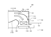
- FIG. 5 is a schematic diagram showing an example of the structure of bathroom dryer 100 in embodiment 1.
- Bathroom dryer 100 is installed through an opening formed in ceiling surface 151 of bathroom 150, which is an example of a room, passing from bathroom 150 to the attic 152.
- the bathroom dryer 100 comprises a housing 110 and a ventilation duct connection part 113.
- the housing 110 has an internal air passage, a housing main body 111 with an opening on the side facing the bathroom 150, and an orifice 112, which is a bottom plate provided at the opening of the housing main body 111 and is provided to cover the opening of the housing main body 111.
- the orifice 112 has an intake port 121 that draws in air from inside the bathroom 150, and a circulation outlet port 122 that blows air into the bathroom 150.
- the housing 110 has a hollow rectangular parallelepiped shape.
- the housing 110 has a ventilation connection port 123 at a position corresponding to the circulation outlet 122 on the surface facing the orifice 112.
- the circulation outlet 122 corresponds to an outlet that blows air sucked in from the intake port 121 into the bathroom 150.
- the ventilation connection port 123 corresponds to an exhaust port that exhausts air sucked in from the intake port 121 to the outdoors.
- the ventilation duct connection part 113 is provided so as to cover the ventilation connection port 123 of the housing main body part 111 from the outside.
- the ventilation duct connection part 113 is connected to a ventilation duct (not shown) that exhausts the air inside the bathroom 150 to the outside.
- the ventilation duct connection part 113 has a ventilation exhaust port 1131 at the part that is connected to the ventilation duct.
- Bathroom dryer 100 is provided with a damper 114 for switching air paths inside housing 110, and a stepping motor 33 (described later) for driving damper 114.
- Damper 114 is provided at a position inside housing 110 where ventilation air path 101 and circulation air path 102 branch off.
- Ventilation air path 101 is an air path that directs air taken into housing 110 to ventilation duct connection 113, and is an air path connecting intake port 121 and ventilation connection port 123.
- Circulation air path 102 is an air path that directs air taken into housing 110 to bathroom 150, and is an air path connecting intake port 121 and circulation outlet 122.
- damper 114 is placed below ventilation connection port 123 inside housing 110, and is formed into a plate shape with flat tip and base ends and a curved middle portion. Damper 114 rotates around damper rotation shaft 1141 provided at the base end.
- Bathroom dryer 100 is equipped with a damper drive mechanism including stepping motor 33 that rotates damper 114 around damper rotation shaft 1141.
- Damper drive mechanism 30 is an example of a drive-related component.
- FIG. 6 is a schematic diagram showing an example of the configuration of a damper drive mechanism in a bathroom dryer according to the first embodiment.
- the damper drive mechanism 30 has a sector gear 31, a small gear 32, and a stepping motor 33.
- the sector gear 31 and the small gear 32 are combined to form a reducer, i.e., a gear, that drives the damper 114.
- the sector gear 31 is fixed to the damper rotating shaft 1141 at the pivot part of the sector.
- the sector gear 31 is also fixed to the base end of the damper 114 at its sector surface.
- the pinion gear 32 is arranged so as to mesh with the teeth of the sector gear 31.
- the stepping motor 33 is a driving means for rotating the pinion gear 32 around the center of the pinion gear 32 as an axis.
- the pinion gear 32 is connected to a rotating shaft which is the output shaft of the stepping motor 33, and can be rotated by the stepping motor 33.
- the small gear 32 fixed to the rotation shaft of the stepping motor 33 rotates, and the sector gear 31 rotates around the damper rotation shaft 1141 in response to the rotation of the small gear 32. Since the damper 114 is fixed to the sector gear 31 and the damper rotation shaft 1141, the damper 114 rotates around the damper rotation shaft 1141 in response to the rotation of the sector gear 31. In other words, the rotation is transmitted from the small gear 32 attached to the rotation shaft of the stepping motor 33 to the sector gear 31 attached to the damper rotation shaft 1141, driving the damper 114.
- the degree of opening of the ventilation air passage 101 and the circulation air passage 102 is adjusted by rotating the damper 114.
- the damper 114 in order to position the stepping motor 33, i.e., to determine the reference position, the damper 114 is rotated and abutted against the inside of the housing 110. After this, the power supply to the stepping motor 33 is temporarily stopped, and the stress on the parts related to the stepping motor 33 and the damper 114 is released, and then excitation is performed.
- Bathroom dryer 100 has blower 115, motor 116, heater 117, filter 118, design panel 119, and control unit 120.
- Blower 115 is provided inside housing 110. Blower 115 takes in air from bathroom 150 through suction port 121 into housing 110, generating air flow inside housing 110.
- blower 115 is a single-suction sirocco fan blower. In the example of FIG. 5, blower 115 is arranged upstream of ventilation air duct 101 and circulation air duct 102 so as to face suction port 121. Motor 116 drives blower 115. In the example of FIG. 5, motor 116 is arranged outside housing 110.
- the heater 117 is a heating unit that heats the air taken into the housing 110.
- the heater 117 is disposed near the circulation outlet 122.
- the heater 117 may be capable of switching the heating intensity.
- the heater 117 is an electric heater 117.
- the filter 118 is disposed upstream of the intake port 121.
- the filter 118 removes dust and other particles from the air.
- the decorative panel 119 covers the surface of the housing 110 facing the bathroom 150. In other words, the decorative panel 119 covers the part of the housing 110 exposed to the bathroom 150.
- the decorative panel 119 is formed flat and is attached with a gap between the ceiling surface 151 and the outer peripheral upward side wall of the decorative panel 119. As a result, air from the bathroom 150 is sucked into the housing 110 from the gap between the ceiling surface 151 and the decorative panel 119, which extends around the entire circumference of the decorative panel 119.
- An opening, the blowing section 1191 is provided at a position on the decorative panel 119 corresponding to the circulation blowing port 122. The air that flows through the circulation air passage 102 is blown out from the blowing section 1191 into the bathroom 150.
- the control unit 120 controls the bathroom dryer 100.
- the control unit 120 has a memory element in which a predetermined control program is stored, and responds to operation instructions input from the operation device 8 or remote control terminal 6 by individually controlling the blower 115, heater 117, and damper 114, causing the bathroom dryer 100 to perform heating operation, ventilation operation, drying operation, etc.
- Bathroom dryer 100 drives blower 115 to take air from bathroom 150 into casing 110.
- heating operation bathroom dryer 100 blows air that has passed through circulating air duct 102 and been heated by heater 117 into bathroom 150.
- ventilation operation bathroom dryer 100 sends air from ventilation air duct 101 to ventilation duct connection 113.
- drying operation bathroom dryer 100 sends air that has been taken into casing 110 from ventilation air duct 101 to ventilation duct connection 113, and blows air that has passed through circulating air duct 102 and been heated by heater 117 into bathroom 150.
- bathroom dryer 100 may blow cool air into bathroom 150 instead of warm air. Switching between heating operation, ventilation operation, and drying operation is performed by the position of damper 114.
- the control unit 120 switches between heating operation, ventilation operation, and drying operation by controlling the blower 115, the damper 114, and the heater 117.
- the control unit 120 wants to make the circulation air duct 102 or the ventilation air duct 101 blocked, it rotates the damper 114 to abut against the inside of the housing 110, and after the abutment occurs, it cuts off the power to the stepping motor 33 and releases the stepping motor 33 from holding the rotating shaft, and then it again energizes the stepping motor 33 and holds the rotating shaft so that it does not rotate due to an external force.
- FIG. 7 is a diagram showing the functional configuration of control unit 120 in bathroom dryer 100 of bathroom heating, drying and ventilation system 1 according to embodiment 1.
- Control unit 120 includes a dryer communication unit 1201, a dryer memory unit 1202, and a dryer control unit 1203.
- the dryer communication unit 1201 communicates with the operation communication unit 82 of the operation device 8.
- the dryer communication unit 1201 also connects to the Internet line 9 via the wireless LAN adapter 3 and the broadband router 4, and communicates with the server communication unit 51 of the server 5.
- the dryer communication unit 1201 transmits various types of information received from the operation communication unit 82 of the operation device 8 and the server communication unit 51 of the server 5 to the dryer control unit 1203.
- the dryer communication unit 1201 transmits control instruction information for the bathroom heating, drying and ventilating device 2 received from the operation communication unit 82 of the operation device 8 and the server communication unit 51 of the server 5 to the dryer control unit 1203.
- the dryer communication unit 1201 also transmits various types of information received from the dryer control unit 1203 to the operation communication unit 82 of the operation device 8 or the server communication unit 51 of the server 5.
- the dryer memory unit 1202 stores information used to control the operation device 8.
- the dryer control unit 1203 is a control unit that controls the operation of the entire bathroom dryer 100, and is a control unit that controls the main body unit 7 of the bathroom heating, drying and ventilating device 2.
- the dryer control unit 1203 controls the operation of the bathroom dryer 100 according to the control instruction information for the bathroom heating, drying and ventilating device 2 received from the operation device 8 or the remote operation terminal 6.
- Figure 8 is a diagram showing an example of the state of the air duct during ventilation operation of bathroom dryer 100 in embodiment 1.
- the white arrows in Figure 8 represent the air flow.
- ventilation duct connection part 113 is not shown in Figure 8. The same applies to the following figures.
- the damper 114 is positioned to prevent the air taken into the housing 110 from the bathroom 150 from flowing through the heater 117 to the blowing section 1191, and to allow the air taken into the housing 110 from the bathroom 150 to flow to the ventilation connection port 123, forming the ventilation air passage 101. That is, the damper 114 fully closes the circulation air passage 102 and abuts against a member inside the housing 110. In this example, the tip of the damper 114 abuts against the orifice 112. As a result, the ventilation air passage 101 is formed inside the housing 110. In addition, the reference position is detected by abutting the damper 114 against the orifice 112.
- the position of the damper 114 is based on the position at which the circulation air passage 102 is fully closed and blocked.
- the position of the damper 114 where the circulation air passage 102 is fully closed and the ventilation air passage 101 is fully open is defined as the fully closed position of the damper 114.
- the state of the damper 114 held in the fully closed position is defined as the fully closed state of the damper 114.
- air from the bathroom 150 is drawn into the housing 110 by driving the blower 115.
- the air drawn into the housing 110 by the blower 115 flows through the ventilation air passage 101 from the intake port 121. That is, the air from the bathroom 150 is guided by the damper 114 to the ventilation connection port 123 and exhausted to the outside via the ventilation duct connection part 113.
- damper 114 when switching from heating operation to ventilation operation, from drying operation to ventilation operation, and from stopped to ventilation operation, the damper 114 performs the abutting operation as described above.
- damper 114 performs the abutting operation with its tip in contact with orifice 112. Then, electricity to stepping motor 33 is temporarily stopped to release the stress on the rotating shaft and gear of stepping motor 33, and electricity is then applied again to excite it. This makes it possible to block circulation outlet 122 in a state where the stress on the rotating shaft and gear of stepping motor 33 is weaker than the stress applied during the abutting operation.
- damper 114 is arranged to block ventilation connection port 123 and direct air taken into housing 110 from bathroom 150 toward blowing section 1191 via heater 117, forming circulation air passage 102. That is, damper 114 is in a fully open state in which it opens circulation air passage 102 in a fully open state and blocks ventilation air passage 101 in a fully closed state, and is in a state in which it abuts against a member inside housing 110. In this example, the tip of damper 114 abuts against the top surface of housing 110. As a result, circulation air passage 102 is formed inside housing 110.
- the reference position is detected by abutting damper 114 against the top surface of housing 110. Then, a heating operation is possible in which air taken into housing 110 from bathroom 150 is heated by heater 117 and returned to bathroom 150.
- the position of the damper 114 in which the circulation air passage 102 is fully open and the ventilation air passage 101 is fully closed is referred to as the fully open position of the damper 114.
- the state of the damper 114 held in the fully open position is referred to as the fully open state of the damper 114.
- air from the bathroom 150 is drawn into the housing 110 by driving the blower 115.
- the air drawn into the housing 110 by the blower 115 passes through the circulation air passage 102, is heated by the heater 117, and is then blown out of the circulation outlet 122 through the blowing section 1191 into the bathroom 150.
- FIG 10 is a diagram showing an example of the state of the air duct during drying operation of bathroom dryer 100 according to embodiment 1.
- damper 114 is positioned to form circulation air duct 102, in which part of the air taken into housing 110 from bathroom 150 is heated by heater 117 and returned to bathroom 150 from blowing section 1191, and ventilation air duct 101, in which the remaining air taken into housing 110 from bathroom 150 is exhausted to the outdoors from ventilation connection port 123. That is, damper 114 is held in a position between orifice 112 and the top surface of housing 110. That is, damper 114 does not contact either orifice 112 or the top surface of housing 110.
- the air flow taken into the housing 110 from the bathroom 150 is divided into two, and the circulation air duct 102 that flows toward the heater 117 and the ventilation air duct 101 that flows toward the ventilation connection port 123 are secured inside the housing 110.
- the damper 114 opens both the circulation air duct 102 and the ventilation air duct 101.
- the position of the damper 114 that opens both the circulation air duct 102 and the ventilation air duct 101 is referred to as the half-open position of the damper 114.
- the state of the damper 114 held in the half-open position is referred to as the half-open state of the damper 114.
- warm air is blown into the bathroom 150 for ventilation, allowing the bathroom 150 or clothes hung out to dry in the bathroom 150 to be dried, and the bathroom dryer 100 can function as a warm air dryer.
- the damper 114 does not come into contact with either the orifice 112 or the upper surface of the housing 110. In other words, the damper 114 does not perform abutting operations, so it can be excited immediately after being driven by the stepping motor 33.
- the damper 114 is controlled by a stepping motor to a predetermined half-open position where it does not come into contact with either the orifice 112 or the top surface of the housing 110.
- bathroom dryer 100 can switch between heating operation and drying operation by opening damper 114 fully or opening damper 114 halfway.
- bathroom dryer 100 can switch between heating operation and drying operation simply by switching the control of the rotation angle command, which is a command that indicates the rotation angle of stepping motor 33.
- the rotation angle command is stored in the dryer control unit 1203 as a command corresponding to each of the control commands for heating operation, drying operation, and ventilation operation, which are transmitted from the operating device 8 or the remote control terminal 6 to the dryer control unit 1201.
- the dryer control unit 1203 controls the rotation angle of the stepping motor 33, i.e., the drive of the stepping motor 33, based on the rotation angle command corresponding to each of the control commands for heating operation, drying operation, and ventilation operation.
- the rotation angle command may be stored in the dryer memory unit 1202.
- the fully open state of the circulation air duct 102 in heating operation shown in FIG. 9 is a state in which the stepping motor 33 has been rotated approximately 1000 pulses based on the fully closed state of the circulation air duct 102 in ventilation operation shown in FIG. 8.
- the half-open state of the circulation air duct 102 in drying operation shown in FIG. 10 is a state in which the stepping motor 33 has been rotated approximately 500 pulses based on the fully closed state of the circulation air duct 102 in ventilation operation shown in FIG. 8.
- bathroom dryer 100 can switch between heating operation and drying operation simply by changing the rotation command value of stepping motor 33 from the fully closed state, which corresponds to the fully closed state of circulating air duct 102, so it is possible to add a heating operation function or a drying operation function without adding any special configuration.
- FIG. 11 is a diagram showing the operating device 8 of the bathroom heating, drying and ventilating apparatus 2 according to the first embodiment.
- the operating device 8 has a switch 11 that accepts operations on the main body 7, and a lamp 12 that indicates the state of the main body 7.
- the switches 11 include an operation switch 13, a stop switch 14, a 24-hour ventilation pause switch 15, and a timer switch 16.
- the operation switches 13 include a ventilation switch 13a, a heating switch 13b, and a setting switch 13c for operating the heating temperature setting.
- the operating device 8 accepts an operation to start ventilation operation at the ventilation switch 13a.
- the operating device 8 accepts an operation to start heating operation at the heating switch 13b.
- the operating device 8 accepts an operation to switch to continuous ventilation operation at the 24-hour ventilation pause switch 15.
- the operating device 8 accepts an operation to stop operation at the stop switch 14.
- the main body 7 When the ventilation switch 13a is pressed while the bathroom dryer 100 (main body 7) is stopped or while the main body 7 is performing an operation other than ventilation operation, the main body 7 starts ventilation operation. Also, when the setting switch 13c is operated during ventilation operation, the main body 7 switches the ventilation strength between "strong” and "weak.”
- pressing the heating switch 13b causes the main body 7 to start heating operation.
- the main body 7 also switches the heating strength between “strong” and “weak” by operating the setting switch 13c during heating operation.
- the main unit 7 stops operation.
- Bathroom heating, drying and ventilation device 2 has a 24-hour ventilation function that provides constant ventilation indoors.
- Bathroom heating, drying and ventilation device 2 performs constant ventilation operation to comply with the Building Standards Act during normal times when operation is not being performed by operation on control device 8 or external operation via remote control terminal 6.
- constant ventilation operation bathroom heating, drying and ventilation device 2 exhausts air taken in from the bathroom to the outside of the bathroom.
- constant ventilation operation bathroom heating, drying and ventilation device 2 performs ventilation at a preset air volume.
- Control device 8 accepts operations to temporarily suspend constant ventilation and to cancel the temporary suspension of constant ventilation at 24-hour ventilation temporary stop switch 15.
- the lamps 12 include an operation lamp 12a that indicates the operating state of the main body 7, a constant ventilation lamp 12b that indicates the constant ventilation state, a timer remaining time lamp 12c that displays the remaining time of timer operation, and a remote operation lamp 12d that indicates operation based on remote control by the remote control terminal 6.
- the operation lamps 12a include two lamps that indicate “strong” and “weak” ventilation operation, two lamps that indicate “strong” and “weak” heating operation, and three lamps that indicate the heating set temperature.
- Each lamp included in the operation lamps 12a and the remote operation lamp 12d are display elements that indicate the operating state of the main unit 7.
- the operating device 8 displays the current operating state of the main unit 7 by turning on only the lamp among the operation lamps 12a that indicates the current operating state. Additionally, during timer operation, the operating device 8 displays the remaining time of timer operation using the timer remaining time lamp 12c.
- the constant ventilation lamp 12b is a display element that indicates the constant ventilation status of the main body unit 7.
- the operating device 8 displays the constant ventilation status by turning on the constant ventilation lamp 12b when the main body unit 7 is performing constant ventilation and by flashing the constant ventilation lamp 12c when the main body unit 7 has temporarily stopped constant ventilation.
- the operation device 8 switches the heating set temperature.
- the remote operation lamp 12d of the operating device 8 turns on to indicate that the main body 7 is in remote operation.
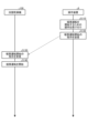
- FIG 12 shows the operating procedure of bathroom dryer 100 and operation device 8 when heating switch 13b is pressed.
- operation device 8 accepts operations to start heating operation.
- the operations to start heating operation are the operation of pressing heating switch 13b and the operation of setting switch 13c.
- operation device 8 sends an instruction to start heating operation to bathroom dryer 100.
- bathroom dryer 100 receives the instruction to start heating operation sent from operation device 8.
- bathroom dryer 100 starts heating operation in accordance with the instruction to start heating operation.
- FIG. 13 is a sequence diagram for explaining the operating procedure of bathroom dryer 100, server 5 and remote control terminal 6 when bathroom dryer 100 according to embodiment 1 is operated in heating operation from remote control terminal 6.
- Fig. 14 is a diagram showing an example of operation screen 66 displayed on terminal display unit 62 of remote control terminal 6 when operating bathroom dryer 100 according to embodiment 1.
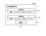
- Fig. 15 is a diagram showing an example of drying operation setting screen 67 displayed on terminal display unit 62 of remote control terminal 6 when remotely operating bathroom dryer 100 according to embodiment 1.
- Fig. 16 is a diagram showing an example of warning screen 68 displayed on terminal display unit 62 of remote control terminal 6 when remotely operating bathroom dryer 100 according to embodiment 1.
- An application for enabling external operation of bathroom dryer 100 is installed on remote control terminal 6.
- the application is provided to the user of bathroom dryer 100 by a business that provides services through the use of bathroom heating, drying and ventilation system 1.
- Operation screen 66 shown in FIG. 14 is displayed by starting the application on remote control terminal 6.
- the operation screen 66 displays operation buttons that accept operations on the bathroom dryer 100, which is the main body 7.
- the operation buttons include a ventilation button 62a, a heating button 62b, a stop button 62c, and a drying (charge) button 62d.
- the remote control terminal 6 accepts an operation to start ventilation operation at the ventilation button 62a.
- the remote control terminal 6 accepts an operation to start heating operation at the heating button 62b.
- the remote control terminal 6 accepts an operation to start drying operation at the drying (charge) button 62d.
- the remote control terminal 6 accepts an operation to stop operation at the stop button 62c.
- the drying (charge) button 62d is a function addition button for adding a remote control function for drying operation to the bathroom dryer 100 for a fee.
- the remote control function for drying operation for a fee can be used after a usage fee is paid to the download source of the application installed on the remote control terminal 6, i.e., the business that provides the service through the use of the application, via a billing system provided by the business.
- the main body 7 When the ventilation button 62a is pressed while the bathroom dryer 100 (main body 7) is stopped or while the main body 7 is performing an operation other than ventilation operation, the main body 7 starts ventilation operation. Furthermore, the main body 7 switches the ventilation strength between “strong” and “weak” by repeatedly pressing the ventilation button 62a during ventilation operation. Note that when the ventilation button 62a is pressed, a setting screen for switching the ventilation strength between “strong” and “weak” is displayed, and the ventilation strength can be selected between “strong” and "weak” on this screen.
- the main body 7 When the heating button 62b is pressed while the bathroom dryer 100 (main body 7) is stopped or while the main body 7 is performing an operation other than heating, the main body 7 starts heating operation. Furthermore, the main body 7 switches the heating strength between “strong” and “weak” by repeatedly pressing the heating button 62b during heating operation. Note that when the heating button 62b is pressed, a settings screen for switching the heating strength between “strong” and “weak” is displayed, and the heating strength can be selected between “strong” and "weak” on this screen.
- a Drying Operation Setting Screen 67 which is a screen for setting the drying operation, is displayed on the terminal display unit 62, as shown in FIG. 15.
- the drying operation setting screen 67 is a screen where the details of the drying operation functions are set, and includes a bathroom drying button 67a, a clothes drying button 67b, and a settings button 67c.
- the remote control terminal 6 accepts operations to set the conditions for bathroom drying operation via the bathroom drying button 67a.
- the "Auto” button on the bathroom drying button 67a is a button for setting automatic operation.
- the “Thorough” button on the bathroom drying button 67a is a button for setting operation that thoroughly dries the bathroom.
- the “Energy saving” button on the bathroom drying button 67a is a button for setting energy saving operation.
- the “Timer” button on the bathroom drying button 67a is a button for setting timer operation.
- the remote control terminal 6 accepts operations for setting the conditions for the clothes drying operation via the clothes drying button 67b.
- the "Auto” button on the clothes drying button 67b is a button for setting automatic operation.
- the “Thorough” button on the clothes drying button 67b is a button for setting an operation that thoroughly dries the clothes.
- the “Energy saving” button on the clothes drying button 67b is a button for setting an energy saving operation.
- the "Timer” button on the clothes drying button 67b is a button for setting a timer operation.
- a warning screen 68 which is a screen for asking the user questions and encouraging them to be careful before the drying operation starts, is displayed on the terminal display unit 62, as shown in FIG. 16.
- the attention screen 68 displays questions such as "Is there anyone in the bathroom?" and "Is the bathroom door closed?” to prompt the user to be careful before starting the drying operation.
- a drying operation instruction to instruct the drying operation is sent from the terminal control unit 65 to the main unit 7.
- the bathroom dryer 100 which is the main unit 7
- the main unit 7 starts the drying operation according to the drying operation instruction.
- the drying operation instruction includes the detailed conditions of the bathroom drying operation or the detailed conditions of the clothes drying operation set in FIG. 15. Pressing the OK button 68a and the OK button 68b is an input operation of information indicating that the user has confirmed and approved the questions.
- the main body 7 starts ventilation operation only when the Drying (Charge) button 62d is pressed on the operation screen 66 of FIG. 14 on the remote control terminal 6, the conditions for drying operation are set on the drying operation setting screen 67 of FIG. 15, and information is entered on the attention screen 68 of FIG. 16 indicating that all questions have been confirmed and approved.
- the drying operation can be remotely controlled on the remote control terminal 6 by charging.
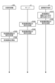
- FIG. 13 shows the operational procedure of bathroom dryer 100, server 5, and remote control terminal 6 when heating button 62b is pressed.
- remote control terminal 6 accepts an operation to start heating operation.
- the operation to start heating operation is an operation to press heating button 62b.
- remote control terminal 6 sends an instruction to start heating operation to server 5.
- step S230 server 5 receives an instruction to start heating operation sent from remote control terminal 6.
- step S240 server 5 sends an instruction to start heating operation to bathroom dryer 100.
- step S250 bathroom dryer 100 receives the instruction to start heating operation sent from server 5.
- step S260 bathroom dryer 100 starts heating operation in accordance with the instruction to start heating operation.
- bathroom dryer 100 sends operation status information to server 5 indicating that heating operation is being performed.
- the operation status information indicates whether the operation currently being performed by bathroom dryer 100 is ventilation operation, heating operation, or drying operation.
- Server 5 receives the operation status information sent from bathroom dryer 100.
- Server 5 sends the operation status information to operation device 8.
- Operation device 8 displays the operation status corresponding to the operation status information with lamp 12.
- FIG. 17 is a sequence diagram for explaining the operating procedure of bathroom dryer 100, server 5, and remote control terminal 6 when bathroom dryer 100 according to embodiment 1 is operated in drying mode from remote control terminal 6.
- FIG. 17 shows the operating procedure of bathroom dryer 100, server 5, and remote control terminal 6 when dry (charge) button 62d is pressed.
- step S310 the remote control terminal 6 accepts an operation to start the drying operation.
- the operation to start the drying operation includes an operation of pressing the Drying (Charge) button 62d on the operation screen of FIG. 14, an operation of setting the conditions for the drying operation on the drying operation setting screen 67 of FIG. 15, and an operation of inputting information to the effect that all questions have been confirmed and approved on the attention screen 68 of FIG. 16.
- step S320 the remote control terminal 6 transmits an instruction to start the drying operation to the server 5.
- step S330 server 5 receives an instruction to start drying operation sent from remote control terminal 6.
- step S340 server 5 sends an instruction to start drying operation to bathroom dryer 100.
- step S350 bathroom dryer 100 receives the instruction to start drying operation sent from server 5.
- step S360 bathroom dryer 100 starts drying operation in accordance with the instruction to start drying operation.
- bathroom dryer 100 which is main body 7, has a ventilation operation function for performing ventilation operation, a heating operation function for performing heating operation, and a drying operation function for performing drying operation.
- remote control terminal 6 has a ventilation operation remote control function for remotely controlling the ventilation operation of bathroom dryer 100, which is main body 7, a heating operation remote control function for remotely controlling the heating operation of bathroom dryer 100, and a drying operation remote control function for remotely controlling the drying operation of bathroom dryer 100.
- operation device 8 has a ventilation operation remote control function for remotely controlling the ventilation operation of bathroom dryer 100, which is main body unit 7, and a heating operation remote control function for remotely controlling the heating operation of bathroom dryer 100, but does not have a drying operation remote control function for remotely controlling the drying operation of bathroom dryer 100.
- operation device 8 has some of the remote control functions out of the multiple remote control functions that remote operation terminal 6 has for remotely controlling the operation of main body unit 7.
- the operating device 8 can accommodate the switch 11 that accepts operations on the main body 7 and the lamp 12 that indicates the state of the main body 7 within a limited space. This allows the operating device 8 to be made smaller, improving the freedom of installation in a home and making it possible to produce it at low cost.
- the operating device 8 has a small number of switches 11 and lamps 12, the user can enjoy the benefit of good visibility of the switches 11 and lamps 12, and the benefit of easy operation of the switches 11 on the operating device 8.
- the operating device 8 has the effect of being able to selectively display the functions required by the user to operate the bathroom dryer 100, as well as the switches and lamps related to the detailed settings of those functions.
- bathroom dryer 100 which is main body 7, can switch between heating operation and drying operation by opening damper 114 fully or halfway. That is, bathroom dryer 100 can switch between heating operation and drying operation simply by switching the control of the rotation angle command, which is a command that indicates the rotation angle of stepping motor 33. Therefore, when using drying operation in response to a fee, bathroom dryer 100 can easily enable the drying operation function without adding special components to achieve drying operation. Therefore, bathroom heating, drying and ventilation system 1 can be implemented inexpensively without the increased cost of special components to achieve drying operation.
- the bathroom heating, drying and ventilation system 1 has the effect of providing a remote control function, while also allowing the user to use the control device 8 to display and set the required functions and their detailed settings.
- Embodiment 2 a modified example of operation device 2 provided in bathroom heating, drying and ventilation system 1 according to embodiment 1 will be described.
- Figure 18 is a diagram showing operation device 8 provided in bathroom heating, drying and ventilation system 1 according to embodiment 2. Functions and processes that differ from those in embodiment 1 will be described below.
- the operating device 8 has a switch 11 that accepts operations on the main body 7, and a lamp 12 that indicates the state of the main body 7.
- the switches 11 include an operation switch 13, a stop switch 14, a 24-hour ventilation pause switch 15, and a timer switch 16.
- the operation switches 13 include a ventilation switch 13a, a drying switch 13d, and a setting switch 13e for operating the drying settings.
- the operating device 8 accepts an operation to start the drying operation at the drying switch 13d.
- the main body 7 When the drying switch 13d is pressed while the bathroom dryer 100 (main body 7) is stopped or while the main body 7 is performing an operation other than a drying operation, the main body 7 starts a drying operation. In addition, the main body 7 switches the strength of the airflow during the drying operation between "strong” and “weak” by operating the setting switch 13e during the drying operation.
- the lamps 12 include an operation lamp 12e that indicates the operating state of the main body 7, a constant ventilation lamp 12b that indicates the constant ventilation state, a timer remaining time lamp 12c that displays the remaining time of timer operation, and a remote operation lamp 12d that indicates operation based on remote operation by the remote operation terminal 6.
- the operation lamps 12e include two lamps that indicate the "strong” and “weak” ventilation operation, two lamps that indicate the “strong” and “weak” drying operation, and two lamps that indicate the operating state of the drying operation, whether the drying operation is in automatic operation or timer operation.
- Each lamp included in the operation lamps 12e and the remote operation lamp 12d are display elements that indicate the operating state of the main body unit 7.
- Figure 19 is a sequence diagram for explaining the operating procedure of bathroom dryer 100 and operation device 8 when bathroom dryer 100 is operated to perform drying operation from operation device 8 in embodiment 2.
- FIG 19 shows the operating procedure of bathroom dryer 100 and operating device 8 when drying switch 13d is pressed.
- operating device 8 accepts an operation to start drying operation.
- the operations to start drying operation are the operation of pressing drying switch 13d and the operation of setting switch 13e.
- operating device 8 sends an instruction to start drying operation to bathroom dryer 100.
- bathroom dryer 100 receives the instruction to start drying operation sent from operating device 8.
- bathroom dryer 100 starts drying operation in accordance with the instruction to start drying operation.
- Figure 20 is a sequence diagram for explaining the operating procedure of bathroom dryer 100, server 5 and remote control terminal 6 when bathroom dryer 100 is operated in heating operation from remote control terminal 6 in embodiment 2.
- Figure 21 is a diagram showing an example of operation screen 69 displayed on terminal display unit 62 of remote control terminal 6 when bathroom dryer 100 is remotely operated in embodiment 2.
- Figure 22 is a diagram showing an example of heating operation setting screen 70 displayed on terminal display unit 62 of remote control terminal 6 when bathroom dryer 100 is remotely operated in embodiment 2.
- Figure 23 is a diagram showing an example of warning screen 71 displayed on terminal display unit 62 of remote control terminal 6 when bathroom dryer 100 is remotely operated in embodiment 2.
- the operation screen 69 displays operation buttons that accept operations on the bathroom dryer 100, which is the main body 7.
- the operation buttons include a ventilation button 62a, a drying button 62e, a stop button 62c, and a heating (charge) button 62f.
- the remote control terminal 6 accepts an operation to start drying operation at the drying button 62e.
- the remote control terminal 6 accepts an operation to start heating operation at the heating (charge) button 62f.
- the heating (charge) button 62f is a function addition button for adding a remote control function for heating operation to the bathroom dryer 100 for a fee.
- the remote control function for heating operation for a fee can be used after a usage fee is paid to the download source of the application installed on the remote control terminal 6, i.e., the business that provides the service through the use of the application, via a billing system provided by the business.
- the main body 7 When the drying button 62e is pressed while the bathroom dryer 100 (main body 7) is stopped or while the main body 7 is performing an operation other than a drying operation, the main body 7 starts a drying chamber operation. In addition, the main body 7 switches the airflow strength of the drying operation between “strong” and “weak” by repeatedly pressing the drying button 62e during the drying operation. Note that when the drying button 62e is pressed, a setting screen for switching the airflow strength of the drying operation between "strong” and “weak” is displayed, and the screen may be configured to allow the user to select the airflow strength of the drying operation between "strong” and “weak.”
- a heating operation setting screen 70 which is a screen for setting the heating operation, is displayed on the terminal display unit 62.
- the heating operation setting screen 70 is a screen where the details of the heating operation functions are set, and includes a pre-bath heating temperature setting button 70a, a bathing heating temperature setting button 70b, and a bathing time elapsed notification button 70c.
- the remote control terminal 6 accepts operations to set the heating temperature conditions before bathing via the pre-bath heating temperature setting button 70a.
- the pre-bath heating temperature setting button 70a is provided with multiple temperature setting buttons such as "40°C”, “35°C”, and "30°C”.
- the remote control terminal 6 accepts operations to set the heating temperature conditions during bathing through the bathing heating temperature setting button 70b.
- the bathing heating temperature setting button 70b is provided with multiple temperature setting buttons such as "40°C”, “35°C”, and "30°C”.
- the remote control terminal 6 accepts an operation to set the timer time conditions for notifying the user of the elapsed time since starting bathing through the bathing elapsed time notification button 70c.
- the bathing elapsed time notification button 70c is provided with multiple bathing elapsed time setting buttons such as "10 minutes,” “20 minutes,” and "30 minutes.”
- a warning screen 71 which is a screen for asking the user questions and encouraging them to be careful before the heating operation starts, is displayed on the terminal display unit 62, as shown in FIG. 23.
- the warning screen 71 displays questions such as "Is there anyone in the bathroom?" and "Do you want to start taking a bath?" to alert the user before starting heating operation.
- a heating operation instruction to start heating operation is sent from the terminal control unit 65 to the main unit 7.
- the bathroom dryer 100 which is the main unit 7
- the main unit 7 starts heating operation in accordance with the heating operation instruction.
- the heating operation instruction includes the detailed conditions for heating operation set in FIG. 22. Pressing the OK button 71a and the start button 71b is an input operation of information that the user has confirmed and approved the questions.
- the main unit 7 starts heating operation only when the heating (charge) button 62f is pressed on the operation screen 69 of FIG. 21 on the remote control terminal 6, the heating operation conditions are set on the heating operation setting screen 70 of FIG. 22, and information is entered on the attention screen 71 of FIG. 23 indicating that all questions have been confirmed and approved.
- the remote control terminal 6 allows remote control of heating operation by charging.
- FIG. 20 shows the operation procedure of the bathroom dryer 100, server 5, and remote control terminal 6 when the heating (billing) button 62f is pressed.
- step S510 the remote control terminal 6 accepts an operation to start heating operation.
- operations to start heating operation include an operation of pressing the heating (billing) button 62f on the operation screen of FIG. 21, an operation of setting the heating operation conditions on the heating operation setting screen 70 of FIG. 22, and an operation of inputting information to the effect that all questions have been confirmed and approved on the attention call screen 71 of FIG. 23.
- step S520 the remote control terminal 6 transmits an instruction to start heating operation to the server 5.
- step S530 server 5 receives an instruction to start heating operation sent from remote control terminal 6.
- step S540 server 5 sends an instruction to start heating operation to bathroom dryer 100.
- step S550 bathroom dryer 100 receives the instruction to start heating operation sent from server 5.
- step S560 bathroom dryer 100 starts heating operation in accordance with the instruction to start heating operation.
- the bathroom dryer 100 When the bathroom dryer 100 starts the heating operation, it starts measuring the time that has elapsed since the start of the heating operation, and after the elapsed bathing time set in the elapsed bathing time notification button 70c has elapsed, it sends notification information to the remote control terminal 6 to inform the user that the set elapsed bathing time has elapsed.
- the remote control terminal 6 When the remote control terminal 6 receives the notification information, it displays the notification information on the terminal display unit 62.
- the operating device 8 can arrange the switch 11 for receiving operations to the main body 7 and the lamp 12 for indicating the state of the main body 7 in a limited space. This allows the operating device 8 to be made smaller, improving the freedom of installation in a house and enabling it to be realized at low cost.
- the operating device 8 has a small number of switches 11 and lamps 12, the user can enjoy the benefit of good visibility of the switches 11 and lamps 12, and the benefit of easy operation of the switches 11 on the operating device 8.
- the operating device 8 has the effect of being able to selectively display the functions required by the user to operate the bathroom dryer 100, as well as the switches and lamps related to the detailed settings of those functions.
- the bathroom heating, drying and ventilation system 1 it is possible to obtain a bathroom heating, drying and ventilation system that can be remotely controlled from a remote control terminal other than the control device, and in which the functions that the user wants to operate are provided on the control device.
- the bathroom heating, drying and ventilation system 1 according to the second embodiment has the effect that, while being provided with a remote control function, the control device 8 allows the user to display and set the required functions and their detailed settings.
- the control units 90 according to the first and second embodiments correspond to the operation control unit 84 of the operation device 8, the server control unit 53 of the server 5, the terminal control unit 65 of the remote operation terminal 6, and the dryer control unit 1203 of the control unit 120, respectively, according to the first and second embodiments.
- Each function of the control unit 90 according to the first and second embodiments is realized by a processing circuit.
- the processing circuit may be dedicated hardware, or may be a processing device that executes a program stored in a storage device.
- FIG. 24 is a diagram showing a configuration in which the functions of the control unit 90 in the first and second embodiments are realized by hardware.
- the processing circuit 91 incorporates a logic circuit 91a that realizes the functions of the control unit 90.
- the processing circuit 91 is a processing device, the functions of the control unit 90 are realized by software, firmware, or a combination of software and firmware.
- the processing circuit 91 has a processor 911 that executes the program 91b, a random access memory 912 that the processor 911 uses as a work area, and a storage device 913 that stores the program 91b.
- the processor 911 deploys the program 91b stored in the storage device 913 on the random access memory 912 and executes it, thereby realizing the functions of the control unit 90.
- the software or firmware is written in a programming language and stored in the storage device 913.
- the processor 911 can be exemplified by a central processing unit, but is not limited to this.
- the storage device 913 can be a semiconductor memory such as a RAM (Random Access Memory), a ROM (Read Only Memory), a flash memory, an EPROM (Erasable Programmable Read Only Memory), or an EEPROM (registered trademark) (Electrically Erasable Programmable Read Only Memory).
- the semiconductor memory may be a non-volatile memory or a volatile memory.
- the storage device 913 may be a magnetic disk, a flexible disk, an optical disk, a compact disk, a mini disk, or a DVD (Digital Versatile Disc).
- the processor 911 may output data such as the results of calculations to the storage device 913 for storage, or may store the data in an auxiliary storage device (not shown) via the random access memory 912.
- the processing circuit 91 realizes the functions of the control unit 90 by reading and executing the program 91b stored in the storage device 913. It can also be said that the program 91b causes the computer to execute the procedures and methods for realizing the functions of the control unit 90.
- processing circuit 91 may implement some of the functions of the control unit 90 using dedicated hardware, and some of the functions of the control unit 90 using software or firmware.
- the processing circuit 91 can realize each of the above-mentioned functions through hardware, software, firmware, or a combination of these.
Landscapes
- Engineering & Computer Science (AREA)
- Chemical & Material Sciences (AREA)
- Combustion & Propulsion (AREA)
- Mechanical Engineering (AREA)
- General Engineering & Computer Science (AREA)
- Physics & Mathematics (AREA)
- Thermal Sciences (AREA)
- Computer Hardware Design (AREA)
- Central Heating Systems (AREA)
- Drying Of Solid Materials (AREA)
Abstract
浴室暖房乾燥換気システム(1)は、浴室から取り込まれた空気を浴室へ循環させ、かつ、浴室から取り込まれた空気を浴室の外へ排出させる本体部(7)と、浴室と同じ屋内に設置され、本体部(7)への操作を受け付ける操作装置(8)と、屋内または屋外において使用され、本体部(7)への操作である外部操作を受け付ける遠隔操作端末(6)と、を備える。本体部(7)は、遠隔操作端末(6)からの指示を受信することによって、遠隔操作端末(6)からの外部操作に従って動作可能である。操作装置(8)は、遠隔操作端末(6)が有する本体部(7)を遠隔制御する複数の遠隔制御機能のうち一部の遠隔制御機能を備える。操作装置(8)は、ユーザが必要とする本体部(7)の運転を操作する機能と、当該機能の詳細な設定に関するスイッチおよびランプを選択的に表示できるという効果を有する。
Description
本開示は、遠隔操作端末による遠隔操作が可能な浴室暖房乾燥換気システムに関する。
家庭において使用されるさまざまな電気機器について、遠隔操作端末からの操作を可能としたシステムが知られている。特許文献1には、浴室用の乾燥機を携帯端末で操作可能であり、浴室使用時に不快な操作がされないように浴室近傍に設置された操作部で無線操作の有効、無効を切り替えられる機能を持つ浴室乾燥システムが記載されている。
しかしながら、上記特許文献1にかかる浴室乾燥システムでは、携帯端末からの操作指示を受け付けない機能を有するが、この機能を操作部に設けるためにランプおよび操作スペースを使用してしまうことにより、操作部においてユーザが必要とする機能を減らしてしまう可能性があった。
本開示は、上記に鑑みてなされたものであって、操作装置以外の遠隔操作端末からの遠隔操作が可能であり使用者が操作したい機能を操作装置に設けられる浴室暖房乾燥換気システムを得ることを目的とする。
上述した課題を解決し、目的を達成するために、本開示にかかる浴室暖房乾燥換気システムは、浴室から取り込まれた空気を浴室へ循環させ、かつ、浴室から取り込まれた空気を浴室の外へ排出させる本体部と、浴室と同じ屋内に設置され、本体部への操作を受け付ける操作装置と、屋内または屋外において使用され、本体部への操作である外部操作を受け付ける遠隔操作端末と、を備える。本体部は、遠隔操作端末からの指示を受信することによって、遠隔操作端末からの外部操作に従って動作可能である。操作装置は、遠隔操作端末が有する本体部を遠隔制御する複数の遠隔制御機能のうち一部の遠隔制御機能を備える。
本開示によれば、操作装置以外の遠隔操作端末からの遠隔操作が可能であり使用者が操作したい機能を操作装置に設けられる浴室暖房乾燥換気システムが得られる、という効果を奏する。
以下に、実施の形態にかかる浴室暖房乾燥換気システムを図面に基づいて詳細に説明する。また、以下に示す図面においては、理解の容易のため、各部材の縮尺が実際とは異なる場合がある。各図面間においても同様である。
実施の形態1.
図1は、実施の形態1にかかる浴室暖房乾燥換気装置2を含む浴室暖房乾燥換気システム1の構成例を示す図である。図1に示す浴室暖房乾燥換気システム1は、浴室暖房乾燥換気装置2を含む浴室乾燥システムである。浴室暖房乾燥換気システム1は、浴室暖房乾燥換気装置2と、無線LAN(Local Area Network)アダプタ3と、ブロードバンドルータ4と、サーバ5と、遠隔操作端末6とを有する。
図1は、実施の形態1にかかる浴室暖房乾燥換気装置2を含む浴室暖房乾燥換気システム1の構成例を示す図である。図1に示す浴室暖房乾燥換気システム1は、浴室暖房乾燥換気装置2を含む浴室乾燥システムである。浴室暖房乾燥換気システム1は、浴室暖房乾燥換気装置2と、無線LAN(Local Area Network)アダプタ3と、ブロードバンドルータ4と、サーバ5と、遠隔操作端末6とを有する。
浴室暖房乾燥換気装置2は、家庭において使用される電気機器の1つである。浴室暖房乾燥換気装置2は、換気運転と、暖房運転と、乾燥運転とを行うことができる。浴室暖房乾燥換気装置2は、換気運転により、浴室から取り込まれた空気を浴室の外へ排出させる。浴室暖房乾燥換気装置2は、暖房運転により、浴室から取り込まれた空気を温めて浴室へ温風を循環させる。浴室暖房乾燥換気装置2は、乾燥運転により、浴室から取り込まれた空気を浴室の外へ排出すると同時に、浴室へ温風または涼風を循環させる。
浴室暖房乾燥換気装置2は、浴室暖房乾燥換気装置2の本体である本体部7と、本体部7への操作を受け付ける操作装置8とを有する。
本体部7は、浴室から取り込まれた空気を浴室へ循環させ、かつ、浴室から取り込まれた空気を浴室の外へ排出させる。本体部7は、浴室の天井に設置される。本体部7は、浴室の天井裏に設置されている排気ダクトに接続されている。浴室から排出された空気は、排気ダクトを通じて屋外へ排出される。排気ダクトの図示は省略する。なお、浴室暖房乾燥換気装置2が設置されている家屋の中を屋内、当該家屋の外を屋外と称する。
操作装置8は、浴室暖房乾燥換気装置2を操作するために用いられる専用操作端末である。操作装置8は、配線を介して本体部7に接続されている。操作装置8は、浴室と同じ屋内に設置される。操作装置8は、例えば、浴室に隣接する脱衣室に設置される。なお、操作装置8は、脱衣室以外のスペースに設置されてもよく、浴室に設置されてもよい。操作装置8は、浴室を使用する際に使用者が操作し易い位置に設置される。
図2は、実施の形態1にかかる浴室暖房乾燥換気システム1の操作装置8の機能構成を示す図である。操作装置8は、操作部81と、操作通信部82と、操作記憶部83と、操作制御部84と、を備える。
操作部81は、不図示の、浴室暖房乾燥換気装置2の運転を指示する運転ボタンと、浴室暖房乾燥換気装置2の運転を停止する停止ボタンとを有し、ユーザから浴室暖房乾燥換気装置2の制御の操作を受け付ける入力部である。操作部81は、ボタンを用いてユーザから入力される制御の情報を受け付けて、操作制御部84に送信する。
運転ボタンは、浴室暖房乾燥換気装置2を運転させる操作を受け付ける入力部である。停止ボタンは、浴室暖房乾燥換気装置2を停止させる操作を受け付ける入力部である。
操作通信部82は、本体部7の後述する乾燥機通信部1201との間で通信を行う。
操作記憶部83は、浴室暖房乾燥換気装置2の制御指示情報を含む、各種の情報を記憶する記憶部である。
操作制御部84は、操作装置8全体の処理を制御する制御部である。操作制御部84は、操作部81から送信された浴室暖房乾燥換気装置2の制御指示情報を、操作通信部82を介して浴室暖房乾燥換気装置2の本体部7に送信する。これにより、ユーザは、操作制御部84を用いて浴室暖房乾燥換気装置2の運転を制御することができる。
無線LANアダプタ3は、浴室暖房乾燥換気装置2が浴室暖房乾燥換気装置2の外部の機器と通信するための外付けの通信アダプタである。無線LANアダプタ3は、脱衣室に設置される。無線LANアダプタ3は、本体部7に接続されている。なお、無線LANアダプタ3は、脱衣室以外のスペースに設置されてもよい。無線LANアダプタ3とブロードバンドルータ4とは、無線LANを介して互いに接続される。なお、無線LANアダプタ3は、操作装置8と一体であってもよい。
ブロードバンドルータ4は、屋内に設置される。ブロードバンドルータ4は、無線LANアダプタ3およびインターネット回線9に接続される。
浴室暖房乾燥換気装置2、無線LANアダプタ3およびブロードバンドルータ4は、ホームネットワークシステムを構成する。ブロードバンドルータ4は、インターネット回線9にホームネットワークを接続するためのインタフェースである。なお、ホームネットワークシステムには、浴室暖房乾燥換気装置2以外の電気機器が接続されてもよい。
サーバ5は、情報処理と情報の保持とを担う情報処理装置である。サーバ5は、浴室暖房乾燥換気システム1の利用によるサービスを提供する事業者によって運用される。サーバ5は、インターネット回線9に接続されている。浴室暖房乾燥換気装置2は、インターネット回線9を介してサーバ5と通信する。サーバ5には、クラウドサーバあるいは物理サーバが用いられる。
サーバ5は、浴室暖房乾燥換気装置2の制御を指示する情報である制御指示情報を、遠隔操作端末6から受信する。すなわち、サーバ5は、ユーザが遠隔操作端末6に入力した浴室暖房乾燥換気装置2の制御指示情報を、遠隔操作端末6から受信する。サーバ5は、遠隔操作端末6から受信した制御指示情報を、インターネット回線9を介して浴室暖房乾燥換気装置2に送信する。すなわち、サーバ5は、遠隔操作端末6から受信した制御指示情報を、インターネット回線9、ブロードバンドルータ4、無線LANアダプタ3を介して、浴室暖房乾燥換気装置2の本体部7に送信する。
図3は、実施の形態1にかかる浴室暖房乾燥換気システム1のサーバ5の機能構成を示す図である。サーバ5は、サーバ通信部51と、サーバ記憶部52と、サーバ制御部53と、を備える。
サーバ通信部51は、インターネット回線9に接続し、遠隔操作端末6との間で通信を行う。また、サーバ通信部51は、インターネット回線9に接続し、ブロードバンドルータ4および無線LANアダプタ3を介して浴室暖房乾燥換気装置2の本体部7との間で通信を行う。サーバ通信部51は、遠隔操作端末6または浴室暖房乾燥換気装置2の本体部7から受信した各種情報を、サーバ制御部53に送信する。また、サーバ通信部51は、サーバ制御部53から受信した各種情報を、遠隔操作端末6または浴室暖房乾燥換気装置2の本体部7に送信する。
サーバ記憶部52は、遠隔操作端末6から取得した制御指示情報を含む、サーバ5の処理に関する各種の情報を記憶する。
サーバ制御部53は、サーバ5全体の処理を制御する制御部である。サーバ制御部53は、遠隔操作端末6から送信された浴室暖房乾燥換気装置2の制御指示情報を受信する処理を制御する。サーバ制御部53は、遠隔操作端末6から送信された浴室暖房乾燥換気装置2の制御指示情報を、浴室暖房乾燥換気装置2の本体部7に送信する処理を制御する。
遠隔操作端末6は、浴室暖房乾燥換気装置2を操作するために用いられる操作端末であり、浴室暖房乾燥換気装置2の制御指示情報を浴室暖房乾燥換気装置2に対して送信可能な通信端末である。遠隔操作端末6は、アクセスポイントまたは基地局を介してインターネット回線9に接続される。アクセスポイントおよび基地局の図示は省略する。遠隔操作端末6は、インターネット回線9を介してサーバ5と通信する。なお、遠隔操作端末6とブロードバンドルータ4とが無線LANを介して互いに接続可能である場合、遠隔操作端末6は、屋内において、ブロードバンドルータ4を介してインターネット回線9へ接続されてもよい。
遠隔操作端末6には、スマートフォンおよびタブレット端末といった、携帯可能な無線通信情報端末が用いられる。また、遠隔操作端末6には、据え置き型のパーソナルコンピュータが用いられてもよい。パーソナルコンピュータは、ブロードバンドルータ4を介してインターネット回線9に接続する。
図4は、実施の形態1にかかる浴室暖房乾燥換気システム1の遠隔操作端末6の機能構成を示す図である。遠隔操作端末6は、端末操作部61と、端末表示部62と、端末記憶部63と、端末通信部64と、端末制御部65と、を備える。
端末操作部61は、ユーザからの設定操作を受け付ける入力部である。端末操作部61は、ユーザから設定入力される浴室暖房乾燥換気装置2の制御指示情報を受け付けて、当該制御指示情報を端末記憶部63および端末制御部65に送信する。
端末表示部62は、各種情報を表示する表示部である。
端末記憶部63は、浴室暖房乾燥換気装置2の制御指示情報を含む、各種の情報を記憶する記憶部である。
端末通信部64は、公衆回線と無線通信を行い、公衆回線を介してインターネット回線9に接続し、サーバ5との間で通信を行う。
端末制御部65は、遠隔操作端末6全体の処理を制御する制御部である。端末制御部65は、端末操作部61から送信された浴室暖房乾燥換気装置2の制御指示情報を、端末通信部64を介してサーバ5に送信する。すなわち、端末制御部65は、サーバ5とブロードバンドルータ4と無線LANアダプタ3とを介して浴室暖房乾燥換気装置2の本体部7に制御指示情報の情報を送信する。これにより、ユーザは、遠隔操作端末6を用いて浴室暖房乾燥換気装置2の運転を制御することができる。
つぎに、浴室暖房乾燥換気装置2の本体部7である浴室乾燥機100の構成について説明する。本体部7である浴室乾燥機100は、換気運転を行う換気運転機能と、暖房運転を行う暖房運転機能と、乾燥運転を行う乾燥運転機能と、を有する。図5は、実施の形態1にかかる浴室乾燥機100の構造の一例を模式的に示す図である。浴室乾燥機100は、室内の一例である浴室150の天井面151に形成されている開口において浴室150から天井裏152の方へ通されて設置される。
浴室乾燥機100は、筐体110と、換気ダクト接続部113と、を備える。
筐体110は、内部に風路が構成され、浴室150に対向する側の面が開口している筐体本体部111と、筐体本体部111の開口に設けられる底板であり、筐体本体部111の開口を覆うように設けられるオリフィス112と、を有する。
オリフィス112は、浴室150の内部の空気を吸い込む吸込口121と、浴室150の内部に空気を吹き出す循環吹出口122と、を有する。
筐体110は、一例では中空の直方体形状を有する。筐体110は、一例では、オリフィス112と対向する面における循環吹出口122に対応する位置に、換気接続口123を有する。循環吹出口122は、吸込口121から吸い込んだ空気を浴室150に吹き出す吹出口に対応する。換気接続口123は、吸込口121から吸い込んだ空気を屋外へと排気する排気口に対応する。
換気ダクト接続部113は、筐体本体部111の換気接続口123を外部から覆うように設けられる。換気ダクト接続部113は、浴室150の内部の空気を屋外へと排気する図示しない換気ダクトと接続される。換気ダクト接続部113は、換気ダクトと接続される部分に換気排気口1131を有する。
浴室乾燥機100は、筐体110の内部に、風路を切り換えるためのダンパ114と、ダンパ114を駆動する後述するステッピングモータ33と、を備える。ダンパ114は、筐体110の内部の換気風路101と循環風路102とを分岐させる位置に設けられている。換気風路101は、筐体110の内部へ取り込まれた空気を換気ダクト接続部113へ流す風路であり、吸込口121と換気接続口123とを結ぶ風路である。循環風路102は、筐体110の内部へ取り込まれた空気を浴室150へ流す風路であり、吸込口121と循環吹出口122とを結ぶ風路である。
図5の例では、ダンパ114は、筐体110の内部の換気接続口123の下側に配置され、先端部および基端部が平らであり中間部が湾曲した板状に形成されている。ダンパ114は、基端部に設けられるダンパ回転軸1141の回りに回動する。浴室乾燥機100は、ダンパ回転軸1141の回りにダンパ114を回動させるステッピングモータ33を含むダンパ駆動機構を備える。ダンパ駆動機構30は、駆動関連部品の一例である。
図6は、実施の形態1にかかる浴室乾燥機におけるダンパ駆動機構の構成の一例を模式的に示す図である。ダンパ駆動機構30は、扇状歯車31と、小歯車32と、ステッピングモータ33と、を有する。扇状歯車31と小歯車32とを組み合わせることによって、ダンパ114を駆動する減速機、すなわちギアが構成される。
扇状歯車31は、扇状のかなめ部分でダンパ回転軸1141と固定されている。また、扇状歯車31は、扇面でダンパ114の基端部に固定されている。小歯車32は、扇状歯車31の歯部と噛み合うように配置される。ステッピングモータ33は、小歯車32を小歯車32の中心を軸にして回転させる駆動手段である。すなわち、小歯車32は、ステッピングモータ33の出力軸である回転軸と接続され、ステッピングモータ33により回転可能である。
ステッピングモータ33を駆動させることで、ステッピングモータ33の回転軸に固定されている小歯車32が回転し、小歯車32の回転に対応して扇状歯車31が、ダンパ回転軸1141を中心にして、ダンパ回転軸1141の周りを回動する。扇状歯車31およびダンパ回転軸1141には、ダンパ114が固定されているので、扇状歯車31の回動に対応して、ダンパ回転軸1141を中心としてダンパ114が回動する。つまり、ステッピングモータ33の回転軸に取り付けられた小歯車32から、ダンパ回転軸1141に取り付けられた扇状歯車31へ回転が伝えられ、ダンパ114の駆動が行われる。
そして、ダンパ114が回動されることによって、換気風路101の開度と循環風路102の開度とが調節される。なお、実施の形態1では、ステッピングモータ33の位置出しのために、すなわち基準位置決定のために、ダンパ114を回動させて、ダンパ114を筐体110の内部に突き当てる突き当て動作後に、ステッピングモータ33への通電を一旦停止し、ステッピングモータ33およびダンパ114に関連する部品にかかる応力を解放した後に励磁を行う。
浴室乾燥機100は、送風機115と、モータ116と、ヒータ117と、フィルタ118と、意匠パネル119と、制御部120と、を有する。送風機115は、筐体110の内部に設けられる。送風機115は、吸込口121から浴室150の空気を筐体110の内部に取り込み、筐体110の内部で空気の流れを生じさせる。一例では、送風機115は、片吸込式のシロッコファン送風機である。図5の例では、送風機115は、吸込口121に対向するように、換気風路101および循環風路102の上流側に配置されている。モータ116は、送風機115を駆動する。図5の例では、モータ116は、筐体110の外部に配置されている。
ヒータ117は、筐体110の内部に取り込まれた空気を温める加熱部である。ヒータ117は、循環吹出口122付近に配置されている。ヒータ117は、加熱強度を切り換え可能であってもよい。一例では、ヒータ117は、電気式のヒータ117である。
フィルタ118は、吸込口121の上流側に配置される。フィルタ118は、空気中の埃等を取り除く。意匠パネル119は、筐体110における浴室150側の面を覆う。すなわち、意匠パネル119は、筐体110における浴室150に露出する部分を覆う。意匠パネル119は、フラットに形成されていて、天井面151と意匠パネル119の外周上向き側壁との間に間隙を空けて取付けられる。これにより、意匠パネル119全周に亘る、天井面151と意匠パネル119との隙間から筐体110の内部に浴室150の空気が吸込まれる。意匠パネル119における循環吹出口122に対応する位置には、開口である吹出部1191が設けられる。循環風路102を流れた空気が、吹出部1191から浴室150に吹き出される。
制御部120は、浴室乾燥機100を制御する。具体的には、制御部120は、予め定められた制御プログラムが格納された記憶素子を備え、操作装置8あるいは遠隔操作端末6から入力された運転指示に対応して、送風機115、ヒータ117およびダンパ114をそれぞれ個別に制御し、浴室乾燥機100に暖房運転、換気運転、乾燥運転等を行わせる。
浴室乾燥機100は、送風機115を駆動することによって浴室150の空気を筐体110の内部へ取り込む。暖房運転において、浴室乾燥機100は、循環風路102を通りヒータ117によって加熱された空気を浴室150へ吹き出す。換気運転において、浴室乾燥機100は、換気風路101から換気ダクト接続部113へ空気を送り出す。乾燥運転において、浴室乾燥機100は、筐体110の内部へ取り込まれた空気を、換気風路101から換気ダクト接続部113へ送り出すとともに、循環風路102を通りヒータ117によって加熱された空気を浴室150へ吹き出す。乾燥運転において、浴室乾燥機100は、温風ではなく涼風を浴室150へ吹き出してもよい。暖房運転、換気運転および乾燥運転の切り替えは、ダンパ114を配置する位置によって行われる。
制御部120は、送風機115、ダンパ114およびヒータ117を制御することによって、暖房運転と換気運転と乾燥運転との切り換えを行う。実施の形態1では、制御部120は、循環風路102が閉塞されている状態または換気風路101が閉塞されている状態とする場合に、ダンパ114を回転させて、筐体110の内部にダンパ114を突き当て、突き当てが発生した後に、ステッピングモータ33への通電を切って、ステッピングモータ33の回転軸の保持を開放させた後、再びステッピングモータ33に通電し、回転軸が外力によって回転しないように回転軸を保持させる。
図7は、実施の形態1にかかる浴室暖房乾燥換気システム1の浴室乾燥機100における制御部120の機能構成を示す図である。制御部120は、乾燥機通信部1201と、乾燥機記憶部1202と、乾燥機制御部1203とが、実装されている。
乾燥機通信部1201は、操作装置8の操作通信部82との間で通信を行う。また、乾燥機通信部1201は、無線LANアダプタ3およびブロードバンドルータ4を介してインターネット回線9に接続し、サーバ5のサーバ通信部51との間で通信を行う。
乾燥機通信部1201は、操作装置8の操作通信部82およびサーバ5のサーバ通信部51から受信した各種情報を乾燥機制御部1203に送信する。乾燥機通信部1201は、操作装置8の操作通信部82およびサーバ5のサーバ通信部51から受信した浴室暖房乾燥換気装置2の制御指示情報を乾燥機制御部1203に送信する。また、乾燥機通信部1201は、乾燥機制御部1203から受信した各種情報を、操作装置8の操作通信部82またはサーバ5のサーバ通信部51に送信する。
乾燥機記憶部1202は、操作装置8の制御に用いられる情報を記憶する。
乾燥機制御部1203は、浴室乾燥機100全体の動作を制御する制御部であり、浴室暖房乾燥換気装置2の本体部7を制御する制御部である。乾燥機制御部1203は、操作装置8または遠隔操作端末6から受信した浴室暖房乾燥換気装置2の制御指示情報に従って、浴室乾燥機100の運転を制御する。
次に、実施の形態1の浴室乾燥機100の換気運転、暖房運転および乾燥運転について説明する。図8は、実施の形態1にかかる浴室乾燥機100の換気運転時の風路の状態の一例を示す図である。図8中の白抜き矢印は、空気の流れを表している。また、図8では、換気ダクト接続部113の図示を省略している。以下の図でも同様である。
換気運転では、浴室150から筐体110の内部に取り込まれた空気がヒータ117を介して吹出部1191へと向かうことを防ぎ、浴室150から筐体110の内部に取り込まれた空気が換気接続口123へと流れるようにダンパ114が配置されて、換気風路101が形成される。すなわち、ダンパ114は、循環風路102を全閉状態とし、筐体110の内部で部材に突き当たる状態となる。この例では、ダンパ114の先端部がオリフィス112に突き当たる状態となっている。これによって、筐体110の内部には、換気風路101が形成される。また、ダンパ114をオリフィス112に突き当てることで、基準位置が検出される。実施の形態1では、ダンパ114の位置を、循環風路102を全閉状態として塞ぐ位置を基準とする。循環風路102を全閉状態として塞ぐとともに換気風路101を全開状態として開くダンパ114の位置を、ダンパ114の全閉位置とする。全閉位置に保持されたダンパ114の状態を、ダンパ114の全閉状態とする。
換気運転時には、送風機115を駆動することによって、浴室150の空気が筐体110の内部に取り込まれる。送風機115によって筐体110の内部に取り込まれた空気は、吸込口121から換気風路101を流れる。すなわち、浴室150の空気は、ダンパ114により換気接続口123へと導かれ、換気ダクト接続部113を介して屋外へと排気される。
浴室乾燥機100では、暖房運転から換気運転、乾燥運転から換気運転、停止から換気運転への各運転切り替え時に、上記したようにダンパ114の突き当て動作を行う。循環吹出口122を塞ぐために、ダンパ114は、先端部をオリフィス112に接触させた状態で、突き当て動作を実施する。その後、ステッピングモータ33への通電を一旦止めて、ステッピングモータ33の回転軸およびギアにかかる応力を解放してから再び通電し励磁を行う。これによって、ステッピングモータ33の回転軸およびギアにかかる応力が突き当て動作時にかかる応力に比して弱い状態で、循環吹出口122を塞ぐことが可能となる。
図9は、実施の形態1にかかる浴室乾燥機100の暖房運転時の風路の状態の一例を示す図である。暖房運転では、換気接続口123を塞ぎ、浴室150から筐体110の内部に取り込まれた空気がヒータ117を介して吹出部1191へ向かうようにダンパ114が配置されて、循環風路102が形成される。すなわち、ダンパ114は、循環風路102を全開状態として開くとともに換気風路101を全閉状態として塞ぐ全開状態となり、筐体110の内部で部材に突き当たる状態となる。この例では、ダンパ114の先端部が筐体110の上面に突き当たる状態となっている。これによって、筐体110の内部には、循環風路102が形成される。また、ダンパ114を筐体110の上面に突き当てることで、基準位置が検出される。そして、浴室150から筐体110の内部に取り込まれた空気をヒータ117で加熱して浴室150に戻す暖房運転が可能となる。循環風路102を全開状態として開くとともに換気風路101を全閉状態として塞ぐダンパ114の位置を、ダンパ114の全開位置とする。全開位置に保持されたダンパ114の状態を、ダンパ114の全開状態とする。
暖房運転時には、送風機115を駆動することによって、浴室150の空気が筐体110の内部に取り込まれる。送風機115によって筐体110の内部に取り込まれた空気は、循環風路102を通り、ヒータ117によって加熱された後に、循環吹出口122を介して吹出部1191から浴室150に吹き出される。
浴室乾燥機100では、換気運転から暖房運転、乾燥運転から暖房運転、停止から暖房運転への各運転切り替え時に、上記したようにダンパ114の突き当て動作を行う。換気接続口123を塞ぐために、ダンパ114は、先端部を筐体110の上面に接触させた状態で、突き当て動作を実施する。その後、ステッピングモータ33への通電を一旦止めて、応力を解放してから再び通電して励磁を行う。これによって、ステッピングモータ33の回転軸およびギアにかかる応力が突き当て動作時にかかる応力に比して弱い状態で、換気接続口123を塞ぐことが可能となる。
図10は、実施の形態1にかかる浴室乾燥機100の乾燥運転時の風路の状態の一例を示す図である。乾燥運転では、浴室150から筐体110の内部に取り込んだ空気の一部をヒータ117で加熱して吹出部1191から浴室150に戻す循環風路102と、浴室150から筐体110の内部に取り込んだ空気のうち残りの空気を換気接続口123から屋外へ排気する換気風路101と、を形成するようにダンパ114が配置される。つまり、ダンパ114は、オリフィス112と筐体110の上面との間の位置に保持される。すなわち、ダンパ114は、オリフィス112および筐体110の上面のいずれにも接触しない。これによって、浴室150から筐体110の内部に取り込まれた空気の流れが2つに分けられ、ヒータ117の方向へ向かう循環風路102と、換気接続口123の方向へ向かう換気風路101と、が筐体110の内部に確保される。乾燥運転では、ダンパ114は、循環風路102と換気風路101との両方の風路が開いた状態とする。循環風路102と換気風路101との両方の風路が開いた状態とするダンパ114の位置を、ダンパ114の半開位置とする。半開位置に保持されたダンパ114の状態を、ダンパ114の半開状態とする。
乾燥運転では、浴室150の内部へ温風を吹出しながら換気を行って、浴室150または浴室150に干された衣類を乾燥することができ、浴室乾燥機100を温風乾燥機として機能させることができる。
乾燥運転時には、ダンパ114は、オリフィス112および筐体110の上面のいずれにも接触しない。すなわちダンパ114は突き当て動作を行わないため、ステッピングモータ33でダンパ114を駆動した後、すぐに励磁することができる。
乾燥運転時には、ダンパ114が、オリフィス112および筐体110の上面のいずれにも接触しない予め定められた半開位置に来るように、ステッピングモータで制御される。
以上のように、実施の形態1にかかる浴室乾燥機100では、ダンパ114を全開状態とするか、ダンパ114を半開状態とするかによって、暖房運転と乾燥運転とを切り替えることができる。すなわち、浴室乾燥機100では、ステッピングモータ33の回転角度を指示する指令である回転角度指令の制御の切り替えのみで、暖房運転と乾燥運転とを切り替えることができる。
回転角度指令は、操作装置8あるいは遠隔操作端末6から乾燥機制御部1201に送信される、暖房運転と乾燥運転と換気運転とのそれぞれの制御指令に対応する指令として乾燥機制御部1203に記憶されている。乾燥機制御部1203は、暖房運転と乾燥運転と換気運転とのそれぞれの制御指令に対応した回転角度指令に基づいてステッピングモータ33の回転角度、すなわちステッピングモータ33の駆動を制御する。なお、回転角度指令は、乾燥機記憶部1202に記憶されてもよい。
例えば、図9に示す暖房運転における循環風路102の全開状態は、図8に示す換気運転における循環風路102の全閉状態を基準として、ステッピングモータ33を1000パルス程度分だけ回転させた状態である。図10に示す乾燥運転における循環風路102の半開状態は、図8に示す換気運転における循環風路102の全閉状態を基準として、ステッピングモータ33を500パルス程度分だけ回転させた状態である。このとき、図8に示す換気運転における循環風路102の全閉状態からのステッピングモータ33の回転指令値を1000パルスあるいは500パルスのどちらかに変更することのみにより、暖房運転と乾燥運転とを切り替えることができる。
すなわち、浴室乾燥機100では、循環風路102の全閉状態に対応するステッピングモータ33の、全閉状態からのステッピングモータ33の回転指令値を変更することのみにより、暖房運転と乾燥運転とを切り替えることができるので、特別な構成を追加せずに暖房運転機能または乾燥運転機能を追加することができる。
図11は、実施の形態1にかかる浴室暖房乾燥換気装置2が有する操作装置8を示す図である。操作装置8は、本体部7への操作を受け付けるスイッチ11と、本体部7の状態を表すためのランプ12とを有する。スイッチ11には、運転スイッチ13と、停止スイッチ14と、24時間換気一時停止スイッチ15と、タイマースイッチ16と、が含まれる。運転スイッチ13には、換気スイッチ13aと、暖房スイッチ13bと、暖房の温度設定を操作するための設定スイッチ13cとが含まれる。
操作装置8は、換気運転を開始するための操作を換気スイッチ13aにおいて受け付ける。操作装置8は、暖房運転を開始するための操作を暖房スイッチ13bにおいて受け付ける。操作装置8は、常時換気の運転を切り替えるための操作を24時間換気一時停止スイッチ15において受け付ける。操作装置8は、運転を停止するための操作を停止スイッチ14において受け付ける。
本体部7である浴室乾燥機100が運転を停止しているとき、または本体部7が換気運転以外の運転を行っているときに、換気スイッチ13aが押下されると、本体部7は、換気運転を開始する。また、本体部7は、換気運転時に設定スイッチ13cが操作されることによって、換気の強さを「強」と「弱」とにおいて切り換える。
本体部7である浴室乾燥機100が運転を停止しているとき、または本体部7が暖房運転以外の運転を行っているときに、暖房スイッチ13bが押下されると、本体部7は、暖房運転を開始する。また、本体部7は、暖房運転時に設定スイッチ13cが操作されることによって、暖房の強さを「強」と「弱」とにおいて切り換える。
本体部7が、換気運転、暖房運転および遠隔操作端末6による遠隔操作に基づく運転のうちのいずれかの運転を行っているときに停止スイッチ14が押下されると、本体部7は、運転を停止する。
浴室暖房乾燥換気装置2は、屋内の常時換気を行う機能である24時間換気機能を有する。浴室暖房乾燥換気装置2は、操作装置8における操作、および遠隔操作端末6での操作である外部操作による運転が行われていない通常時において、建築基準法への対応のための常時換気運転を行う。浴室暖房乾燥換気装置2は、常時換気運転において、浴室から取り込まれた空気を浴室の外へ排出させる。浴室暖房乾燥換気装置2は、常時換気運転により、あらかじめ設定された風量での換気を行う。操作装置8は、常時換気を一時停止するための操作と、常時換気の一時停止を解除するための操作とを、24時間換気一時停止スイッチ15において受け付ける。
ランプ12は、本体部7の運転状態を表す運転ランプ12aと、常時換気の状態を表す常時換気ランプ12bと、タイマー運転の残り時間を表示するタイマー残時間ランプ12cと、遠隔操作端末6による遠隔操作に基づく運転を表す遠隔運転ランプ12dとを含む。
運転ランプ12aには、換気運転の「強」および「弱」のそれぞれを表す2つのランプと、暖房運転の「強」および「弱」のそれぞれを表す2つのランプと、暖房の設定温度を表す3つのランプとが含まれる。運転ランプ12aに含まれる各ランプおよび遠隔運転ランプ12dは、本体部7の運転状態を表す表示要素である。操作装置8は、運転ランプ12aのうち現在の運転状態を表すランプのみを点灯させることによって、本体部7の現在の運転状態を表示する。また、操作装置8は、タイマー運転時には、タイマー残時間ランプ12cによりタイマー運転の残り時間を表示する。
常時換気ランプ12bは、本体部7の常時換気の状態を表す表示要素である。操作装置8は、本体部7が常時換気を行っているときに常時換気ランプ12bを点灯させ、本体部7が常時換気を一時的に停止しているときに常時換気ランプ12cを点滅させることによって、常時換気の状態を表示する。
操作装置8は、暖房運転時において設定スイッチ13cが押下されると、暖房の設定温度を切り替える。
操作装置8は、本体部7が遠隔操作端末6からの乾燥運転操作に基づく運転を行っている場合は、本体部7が遠隔運転中であることを表す遠隔運転ランプ12dが点灯する。
次に、操作装置8から浴室乾燥機100を操作する場合における浴室暖房乾燥換気システム1の動作について説明する。図12は、実施の形態1にかかる浴室乾燥機100が操作装置8から暖房運転が操作される場合における浴室乾燥機100および操作装置8の動作手順を説明するためのシーケンス図である。
図12には、暖房スイッチ13bが押下された場合における浴室乾燥機100および操作装置8の動作手順を示している。ステップS110において、操作装置8は、暖房運転を開始するための操作を受け付ける。暖房運転を開始するための操作は、暖房スイッチ13bを押下する操作および設定スイッチ13cの操作である。ステップS120において、操作装置8は、暖房運転開始の指示を浴室乾燥機100に送信する。ステップS130において、浴室乾燥機100は、操作装置8から送信された暖房運転開始の指示を受信する。ステップS140において、浴室乾燥機100は、暖房運転開始の指示に従って、暖房運転を開始する。
なお、浴室乾燥機100が操作装置8から換気運転が操作される場合も、換気スイッチ13aが操作されることにより、上記と同様の処理により浴室乾燥機100における換気運転が開始される。
次に、遠隔操作端末6から浴室乾燥機100を操作する場合における浴室暖房乾燥換気システム1の動作について説明する。図13は、実施の形態1にかかる浴室乾燥機100が遠隔操作端末6から暖房運転を操作される場合における浴室乾燥機100、サーバ5および遠隔操作端末6の動作手順を説明するためのシーケンス図である。図14は、実施の形態1にかかる浴室乾燥機100を操作する際に遠隔操作端末6の端末表示部62に表示される操作画面66の例を示す図である。図15は、実施の形態1にかかる浴室乾燥機100を遠隔操作する際に遠隔操作端末6の端末表示部62に表示される乾燥運転設定画面67の例を示す図である。図16は、実施の形態1にかかる浴室乾燥機100を遠隔操作する際に遠隔操作端末6の端末表示部62に表示される注意喚起画面68の例を示す図である。
遠隔操作端末6には、浴室乾燥機100の外部操作を実現するためのアプリケーションがインストールされている。当該アプリケーションは、浴室暖房乾燥換気システム1の利用によるサービスを提供する事業者によって、浴室乾燥機100のユーザに提供される。図14に示す操作画面66は、遠隔操作端末6においてアプリケーションを起動することによって表示される。
操作画面66には、本体部7である浴室乾燥機100への操作を受け付ける操作ボタンが表示される。操作ボタンには、換気ボタン62aと、暖房ボタン62bと、停止ボタン62cと、乾燥(課金)ボタン62dと、が含まれる。遠隔操作端末6は、換気運転を開始するための操作を換気ボタン62aにおいて受け付ける。遠隔操作端末6は、暖房運転を開始するための操作を暖房ボタン62bにおいて受け付ける。遠隔操作端末6は、乾燥運転を開始するための操作を乾燥(課金)ボタン62dにおいて受け付ける。遠隔操作端末6は、運転を停止するための操作を停止ボタン62cにおいて受け付ける。乾燥(課金)ボタン62dは、課金により乾燥運転の遠隔制御機能を浴室乾燥機100に追加するための機能追加ボタンである。課金による乾燥運転の遠隔制御機能は、遠隔操作端末6にインストールされているアプリケーションのダウンロード元、すなわち当該アプリケーションの利用によるサービスを提供する事業者が提供する課金システムにより使用料金を当該事業者に支払い後、使用可能となる。
本体部7である浴室乾燥機100が運転を停止しているとき、または本体部7が換気運転以外の運転を行っているときに、換気ボタン62aが押下されると、本体部7は、換気運転を開始する。また、本体部7は、換気運転時に換気ボタン62aの押下が繰り返されることによって、換気の強さを「強」と「弱」とにおいて切り換える。なお、換気ボタン62aが押下されると、換気の強さを「強」と「弱」とにおいて切り換えるための設定画面が表示され、当該画面で換気の強さを「強」と「弱」とにおいて選択する構成とされてもよい。
本体部7である浴室乾燥機100が運転を停止しているとき、または本体部7が暖房運転以外の運転を行っているときに、暖房ボタン62bが押下されると、本体部7は、暖房運転を開始する。また、本体部7は、暖房運転時に暖房ボタン62bの押下が繰り返されることによって、暖房の強さを「強」と「弱」とにおいて切り換える。なお、暖房ボタン62bが押下されると、暖房の強さを「強」と「弱」とにおいて切り換えるための設定画面が表示され、当該画面で暖房の強さを「強」と「弱」とにおいて選択する構成とされてもよい。
本体部7である浴室乾燥機100が運転を停止しているとき、または本体部7が乾燥運転以外の運転を行っているときに、乾燥(課金)ボタン62dが押下されると、本体部7は、乾燥運転を開始する。また、乾燥(課金)ボタン62dが押下されると、図15に示すように、乾燥運転の設定を行うための画面である乾燥運転設定画面67が端末表示部62に表示される。
乾燥運転設定画面67は、乾燥運転の機能の詳細が設定される画面であり、浴室乾燥ボタン67aと、衣類乾燥ボタン67bと、設定ボタン67cと、が含まれる。
遠隔操作端末6は、浴室乾燥運転の条件を設定するための操作を浴室乾燥ボタン67aにおいて受け付ける。浴室乾燥ボタン67aにおける「自動」のボタンは、自動運転を設定するためのボタンである。浴室乾燥ボタン67aにおける「しっかり」のボタンは、浴室をしっかりと乾燥させる運転を設定するためのボタンである。浴室乾燥ボタン67aにおける「省エネ」のボタンは、省エネルギー運転を設定するためのボタンである。浴室乾燥ボタン67aにおける「タイマー」のボタンは、タイマー運転を設定するためのボタンである。
遠隔操作端末6は、衣類乾燥運転の条件を設定するための操作を衣類乾燥ボタン67bにおいて受け付ける。衣類乾燥ボタン67bにおける「自動」のボタンは、自動運転を設定するためのボタンである。衣類乾燥ボタン67bにおける「しっかり」のボタンは、衣類をしっかりと乾燥させる運転を設定するためのボタンである。衣類乾燥ボタン67bにおける「省エネ」のボタンは、省エネルギー運転を設定するためのボタンである。衣類乾燥ボタン67bにおける「タイマー」のボタンは、タイマー運転を設定するためのボタンである。
浴室乾燥ボタン67aを押下することによって浴室乾燥運転の条件が設定された後に、あるいは衣類乾燥ボタン67bを押下することによって衣類乾燥運転の条件が設定された後に、設定ボタン67cが押下されると、図16に示すように、乾燥運転の開始前にユーザに質問を行って注意喚起を促すための画面である注意喚起画面68が端末表示部62に表示される。
注意喚起画面68には、図16に示すように、「浴室に人はいませんか?」、「浴室の扉は閉めましたか?」といった、ユーザに乾燥運転の開始前の注意喚起を促す質問が表示される。ユーザが「浴室に人はいませんか?」の質問に対するOKボタン68aを押下し、「浴室の扉は閉めましたか?」の質問に対するOKボタン68bを押下すると、乾燥運転を指示する乾燥運転指示が端末制御部65から本体部7に送信される。そして、本体部7である浴室乾燥機100が運転を停止しているとき、または本体部7が乾燥運転以外の運転を行っているときに、本体部7は、乾燥運転指示に従って乾燥運転を開始する。乾燥運転指示には、図15において設定された浴室乾燥運転の詳細条件あるいは衣類乾燥運転の詳細条件が含まれている。OKボタン68aおよびOKボタン68bの押下は、ユーザによる質問事項を確認および承認した旨の情報の入力操作である。
すなわち、本体部7は、遠隔操作端末6において、図14の操作画面66で乾燥(課金)ボタン62dが押下され、図15の乾燥運転設定画面67で乾燥運転の条件が設定され、図16の注意喚起画面68で全ての質問事項を確認および承認した旨の情報が入力された場合に、初めて換気運転を開始する。すなわち、遠隔操作端末6では、課金することにより、乾燥運転の遠隔制御が可能となる。
図13には、暖房ボタン62bが押下された場合における浴室乾燥機100、サーバ5および遠隔操作端末6の動作手順を示している。ステップS210において、遠隔操作端末6は、暖房運転を開始するための操作を受け付ける。暖房運転を開始するための操作は、暖房ボタン62bを押下する操作である。ステップS220において、遠隔操作端末6は、暖房運転開始の指示をサーバ5へ送信する。
ステップS230において、サーバ5は、遠隔操作端末6から送信された暖房運転開始の指示を受信する。ステップS240において、サーバ5は、暖房運転開始の指示を浴室乾燥機100へ送信する。ステップS250において、浴室乾燥機100は、サーバ5から送信された暖房運転開始の指示を受信する。ステップS260において、浴室乾燥機100は、暖房運転開始の指示に従って、暖房運転を開始する。
なお、暖房運転を開始すると、浴室乾燥機100は、暖房運転が行われていることを示す運転状態情報をサーバ5へ送信する。運転状態情報は、浴室乾燥機100が現在行っている運転が、換気運転、暖房運転および乾燥運転のいずれであるかを示す情報である。サーバ5は、浴室乾燥機100から送信された運転状態情報を受信する。サーバ5は、運転状態情報を操作装置8に送信する。操作装置8は、運転状態情報に対応する運転状態をランプ12で表示する。
図17は、実施の形態1にかかる浴室乾燥機100が遠隔操作端末6から乾燥運転を操作される場合における浴室乾燥機100、サーバ5および遠隔操作端末6の動作手順を説明するためのシーケンス図である。図17には、乾燥(課金)ボタン62dが押下された場合における浴室乾燥機100、サーバ5および遠隔操作端末6の動作手順を示している。
ステップS310において、遠隔操作端末6は、乾燥運転を開始するための操作を受け付ける。ここで、乾燥運転を開始するための操作は、図14の操作画面で乾燥(課金)ボタン62dが押下される操作、図15の乾燥運転設定画面67で乾燥運転の条件が設定される操作、および図16の注意喚起画面68で全ての質問事項を確認および承認した旨の情報が入力される操作が含まれる。ステップS320において、遠隔操作端末6は、乾燥運転開始の指示をサーバ5へ送信する。
ステップS330において、サーバ5は、遠隔操作端末6から送信された乾燥運転開始の指示を受信する。ステップS340において、サーバ5は、乾燥運転開始の指示を浴室乾燥機100へ送信する。ステップS350において、浴室乾燥機100は、サーバ5から送信された乾燥運転開始の指示を受信する。ステップS360において、浴室乾燥機100は、乾燥運転開始の指示に従って、乾燥運転を開始する。
上述したように、実施の形態1にかかる浴室暖房乾燥換気システム1は、本体部7である浴室乾燥機100が、換気運転を行う換気運転機能と、暖房運転を行う暖房運転機能と、乾燥運転を行う乾燥運転機能と、を有する。また、遠隔操作端末6は、本体部7である浴室乾燥機100の換気運転を遠隔操作する換気運転遠隔操作機能と、浴室乾燥機100の暖房運転を遠隔操作する暖房運転遠隔操作機能と、浴室乾燥機100の乾燥運転を遠隔操作する乾燥運転遠隔操作機能とを有する。
一方、操作装置8は、本体部7である浴室乾燥機100の換気運転を遠隔操作する換気運転遠隔操作機能と、浴室乾燥機100の暖房運転を遠隔操作する暖房運転遠隔操作機能とを有し、浴室乾燥機100の乾燥運転を遠隔操作する乾燥運転遠隔操作機能は有していない。すなわち、操作装置8は、遠隔操作端末6が有している本体部7の運転を遠隔制御するための複数の遠隔制御機能のうち、一部の遠隔制御機能を有している。
これにより、操作装置8は、本体部7への操作を受け付けるスイッチ11と、本体部7の状態を表すためのランプ12とを、限られたスペースの中で配置することができる。このため、操作装置8は、小型化が可能となり、家屋における設置の自由度が向上し、また安価に実現可能となる。
また、操作装置8ではスイッチ11とランプ12との数が少数とされるため、ユーザは、スイッチ11とランプ12との視認性が良好となるというメリットを享受でき、また操作装置8におけるスイッチ11の操作を行い易いというメリットを享受できる。すなわち、操作装置8は、ユーザが必要とする浴室乾燥機100の運転を操作する機能と、当該機能の詳細な設定に関するスイッチおよびランプを選択的に表示できるという効果を有する。
また、本体部7である浴室乾燥機100は、ダンパ114を全開状態とするか、あるいは半開状態とするかによって、暖房運転と乾燥運転とを切り替えることができる。すなわち、浴室乾燥機100では、ステッピングモータ33の回転角度を指示する指令である回転角度指令の制御の切り替えのみで、暖房運転と乾燥運転とを切り替えることができる。このため、浴室乾燥機100は、課金によって乾燥運転を使用するときに、乾燥運転を実現するための特別な構成部品を追加することなく、乾燥運転機能を容易に使用可能とすることができる。したがって、浴室暖房乾燥換気システム1は、乾燥運転を実現するための特別な構成部品によるコストの増加が無く、安価に実現可能である。
したがって、操作装置以外の遠隔操作端末からの遠隔操作が可能であり使用者が操作したい機能を操作装置に設けられる浴室暖房乾燥換気システムが得られる、という効果を奏する。すなわち、実施の形態1にかかる浴室暖房乾燥換気システム1は、遠隔操作機能を備えつつ、操作装置8では、ユーザが必要な機能とその詳細設定と表示をできるという効果を奏する。
実施の形態2.
実施の形態2では、上述した実施の形態1にかかる浴室暖房乾燥換気システム1が有する操作装置2の変形例について説明する。図18は、実施の形態2における浴室暖房乾燥換気システム1が有する操作装置8を示す図である。以下では、実施の形態1の場合と異なる機能および処理について説明する。
実施の形態2では、上述した実施の形態1にかかる浴室暖房乾燥換気システム1が有する操作装置2の変形例について説明する。図18は、実施の形態2における浴室暖房乾燥換気システム1が有する操作装置8を示す図である。以下では、実施の形態1の場合と異なる機能および処理について説明する。
実施の形態2において、操作装置8は、本体部7への操作を受け付けるスイッチ11と、本体部7の状態を表すためのランプ12とを有する。スイッチ11には、運転スイッチ13と、停止スイッチ14と、24時間換気一時停止スイッチ15と、タイマースイッチ16と、が含まれる。実施の形態2では、運転スイッチ13には、換気スイッチ13aと、乾燥スイッチ13dと、乾燥の設定を操作するための設定スイッチ13eとが含まれる。
操作装置8は、乾燥運転を開始するための操作を乾燥スイッチ13dにおいて受け付ける。
本体部7である浴室乾燥機100が運転を停止しているとき、または本体部7が乾燥運転以外の運転を行っているときに、乾燥スイッチ13dが押下されると、本体部7は、乾燥運転を開始する。また、本体部7は、乾燥運転時に設定スイッチ13eが操作されることによって、乾燥運転の風量の強さを「強」と「弱」とにおいて切り換える。
ランプ12は、本体部7の運転状態を表す運転ランプ12eと、常時換気の状態を表す常時換気ランプ12bと、タイマー運転の残り時間を表示するタイマー残時間ランプ12cと、遠隔操作端末6による遠隔操作に基づく運転を表す遠隔運転ランプ12dとを含む。
運転ランプ12eには、換気運転の「強」および「弱」のそれぞれを表す2つのランプと、乾燥運転の「強」および「弱」のそれぞれを表す2つのランプと、乾燥運転が自動運転状態であるかあるいはタイマー運転であるかの乾燥運転の運転状態を表す2つのランプとが含まれる。運転ランプ12eに含まれる各ランプおよび遠隔運転ランプ12dは、本体部7の運転状態を表す表示要素である。
次に、操作装置8から浴室乾燥機100を操作する場合における浴室暖房乾燥換気システム1の動作について説明する。図19は、実施の形態2において浴室乾燥機100が操作装置8から乾燥運転が操作される場合における浴室乾燥機100および操作装置8の動作手順を説明するためのシーケンス図である。
図19には、乾燥スイッチ13dが押下された場合における浴室乾燥機100および操作装置8の動作手順を示している。ステップS410において、操作装置8は、乾燥運転を開始するための操作を受け付ける。乾燥運転を開始するための操作は、乾燥スイッチ13dを押下する操作および設定スイッチ13eの操作である。ステップS420において、操作装置8は、乾燥運転開始の指示を浴室乾燥機100に送信する。ステップS430において、浴室乾燥機100は、操作装置8から送信された乾燥運転開始の指示を受信する。ステップS440において、浴室乾燥機100は、乾燥運転開始の指示に従って、乾燥運転を開始する。
次に、実施の形態2において遠隔操作端末6から浴室乾燥機100を操作する場合における浴室暖房乾燥換気システム1の動作について説明する。図20は、実施の形態2において浴室乾燥機100が遠隔操作端末6から暖房運転を操作される場合における浴室乾燥機100、サーバ5および遠隔操作端末6の動作手順を説明するためのシーケンス図である。図21は、実施の形態2において浴室乾燥機100を遠隔操作する際に遠隔操作端末6の端末表示部62に表示される操作画面69の例を示す図である。図22は、実施の形態2において浴室乾燥機100を遠隔操作する際に遠隔操作端末6の端末表示部62に表示される暖房運転設定画面70の例を示す図である。図23は、実施の形態2において浴室乾燥機100を遠隔操作する際に遠隔操作端末6の端末表示部62に表示される注意喚起画面71の例を示す図である。
操作画面69には、本体部7である浴室乾燥機100への操作を受け付ける操作ボタンが表示される。操作ボタンには、換気ボタン62aと、乾燥ボタン62eと、停止ボタン62cと、暖房(課金)ボタン62fと、が含まれる。遠隔操作端末6は、乾燥運転を開始するための操作を乾燥ボタン62eにおいて受け付ける。遠隔操作端末6は、暖房運転を開始するための操作を暖房(課金)ボタン62fにおいて受け付ける。暖房(課金)ボタン62fは、課金により暖房運転の遠隔制御機能を浴室乾燥機100に追加するための機能追加ボタンである。課金による暖房運転の遠隔制御機能は、遠隔操作端末6にインストールされているアプリケーションのダウンロード元、すなわち当該アプリケーションの利用によるサービスを提供する事業者が提供する課金システムにより使用料金を当該事業者に支払い後、使用可能となる。
本体部7である浴室乾燥機100が運転を停止しているとき、または本体部7が乾燥運転以外の運転を行っているときに、乾燥ボタン62eが押下されると、本体部7は、乾燥房運転を開始する。また、本体部7は、乾燥運転時に乾燥ボタン62eの押下が繰り返されることによって、乾燥運転の風量の強さを「強」と「弱」とにおいて切り換える。なお、乾燥ボタン62eが押下されると、乾燥運転の風量の強さを「強」と「弱」とにおいて切り換えるための設定画面が表示され、当該画面で乾燥運転の風量の強さを「強」と「弱」とにおいて選択する構成とされてもよい。
本体部7である浴室乾燥機100が運転を停止しているとき、または本体部7が暖房運転以外の運転を行っているときに、暖房(課金)ボタン62fが押下されると、本体部7は、暖房運転を開始する。また、暖房(課金)ボタン62fが押下されると、図22に示すように、暖房運転の設定を行うための画面である暖房運転設定画面70が端末表示部62に表示される。
暖房運転設定画面70は、暖房運転の機能の詳細が設定される画面であり、入浴前暖房温度設定ボタン70aと、入浴中暖房温度設定ボタン70bと、入浴経過時間お知らせボタン70cと、が含まれる。
遠隔操作端末6は、入浴前の暖房温度の条件を設定するための操作を入浴前暖房温度設定ボタン70aにおいて受け付ける。入浴前暖房温度設定ボタン70aには、「40℃」、「35℃」、「30℃」といった複数の温度設定ボタンが設けられている。
遠隔操作端末6は、入浴中の暖房温度の条件を設定するための操作を入浴中暖房温度設定ボタン70bにおいて受け付ける。入浴中暖房温度設定ボタン70bには、「40℃」、「35℃」、「30℃」といった複数の温度設定ボタンが設けられている。
遠隔操作端末6は、入浴を開始してからの経過時間を知らせる際のタイマー時間の条件を設定するための操作を入浴経過時間お知らせボタン70cにおいて受け付ける。入浴経過時間お知らせボタン70cには、「10分」、「20分」、「30分」といった複数の入浴経過時間設定ボタンが設けられている。
入浴前暖房温度設定ボタン70aと入浴中暖房温度設定ボタン70bと入浴経過時間お知らせボタン70cとにより暖房運転の機能の詳細が設定された後に、設定ボタン70dが押下されると、図23に示すように、暖房運転の開始前にユーザに質問を行って注意喚起を促すための画面である注意喚起画面71が端末表示部62に表示される。
注意喚起画面71には、図23に示すように、「浴室に人はいませんか?」、「入浴を開始しますか?」といった、ユーザに暖房運転の開始前の注意喚起を促す質問が表示される。ユーザが「浴室に人はいませんか?」の質問に対するOKボタン71aを押下し、「入浴を開始しますか?」の質問に対する開始ボタン71bを押下すると、暖房運転を指示する暖房運転指示が端末制御部65から本体部7に送信される。そして、本体部7である浴室乾燥機100が運転を停止しているとき、または本体部7が暖房運転以外の運転を行っているときに、本体部7は、暖房運転指示に従って暖房運転を開始する。暖房運転指示には、図22において設定された暖房運転の詳細条件が含まれている。OKボタン71aおよび開始ボタン71bの押下は、ユーザによる質問事項を確認および承認した旨の情報の入力操作である。
すなわち、本体部7は、遠隔操作端末6において、図21の操作画面69で暖房(課金)ボタン62fが押下され、図22の暖房運転設定画面70で暖房運転の条件が設定され、図23の注意喚起画面71で全ての質問事項を確認および承認した旨の情報が入力された場合に、初めて暖房運転を開始する。すなわち、遠隔操作端末6では、課金することにより、暖房運転の遠隔制御が可能となる。
図20には、暖房(課金)ボタン62fが押下された場合における浴室乾燥機100、サーバ5および遠隔操作端末6の動作手順を示している。
ステップS510において、遠隔操作端末6は、暖房運転を開始するための操作を受け付ける。ここで、暖房運転を開始するための操作は、図21の操作画面で暖房(課金)ボタン62fが押下される操作、図22の暖房運転設定画面70で暖房運転の条件が設定される操作、および図23の注意喚起画面71で全ての質問事項を確認および承認した旨の情報が入力される操作が含まれる。ステップS520において、遠隔操作端末6は、暖房運転開始の指示をサーバ5へ送信する。
ステップS530において、サーバ5は、遠隔操作端末6から送信された暖房運転開始の指示を受信する。ステップS540において、サーバ5は、暖房運転開始の指示を浴室乾燥機100へ送信する。ステップS550において、浴室乾燥機100は、サーバ5から送信された暖房運転開始の指示を受信する。ステップS560において、浴室乾燥機100は、暖房運転開始の指示に従って、暖房運転を開始する。
なお、浴室乾燥機100は、暖房運転を開始すると、暖房運転の開始からの経過時間の計測を開始し、入浴経過時間お知らせボタン70cにおいて設定された入浴経過時間の経過後に、設定された入浴経過時間が経過した旨のお知らせ情報を遠隔操作端末6に送信する。遠隔操作端末6は、お知らせ情報を受信すると、当該お知らせ情報を端末表示部62に表示させる。
上述したように、実施の形態2によれば、実施の形態1と同様に、操作装置8は、本体部7への操作を受け付けるスイッチ11と、本体部7の状態を表すためのランプ12とを、限られたスペースの中で配置することができる。このため、操作装置8は、小型化が可能となり、家屋における設置の自由度が向上し、また安価に実現可能となる。
また、操作装置8ではスイッチ11とランプ12との数が少数とされるため、ユーザは、スイッチ11とランプ12との視認性が良好となるというメリットを享受でき、また操作装置8におけるスイッチ11の操作を行い易いというメリットを享受できる。すなわち、操作装置8は、ユーザが必要とする浴室乾燥機100の運転を操作する機能と、当該機能の詳細な設定に関するスイッチおよびランプを選択的に表示できるという効果を有する。
したがって、実施の形態2によれば、操作装置以外の遠隔操作端末からの遠隔操作が可能であり使用者が操作したい機能を操作装置に設けられる浴室暖房乾燥換気システムが得られる、という効果を奏する。すなわち、実施の形態2にかかる浴室暖房乾燥換気システム1は、遠隔操作機能を備えつつ、操作装置8では、ユーザが必要な機能とその詳細設定と表示をできるという効果を奏する。
続いて、実施の形態1,2にかかる制御部90のそれぞれのハードウェア構成について説明する。実施の形態1,2にかかる制御部90は、実施の形態1,2における、操作装置8の操作制御部84、サーバ5のサーバ制御部53、遠隔操作端末6の端末制御部65、および制御部120の乾燥機制御部1203のそれぞれに対応する。実施の形態1,2にかかる制御部90のそれぞれの機能は、処理回路により実現される。処理回路は、専用のハードウェアであってもよく、記憶装置に格納されるプログラムを実行する処理装置であってもよい。
処理回路が専用のハードウェアである場合、処理回路は、単一回路、複合回路、プログラム化したプロセッサ、並列プログラム化したプロセッサ、特定用途向け集積回路、フィールドプログラマブルゲートアレイ、またはこれらを組み合わせたものが該当する。図24は、実施の形態1,2にかかる制御部90のそれぞれの機能をハードウェアで実現した構成を示す図である。処理回路91には、制御部90の機能を実現する論理回路91aが組み込まれている。
処理回路91が処理装置の場合、制御部90の機能は、ソフトウェア、ファームウェア、またはソフトウェアとファームウェアとの組み合わせにより実現される。
図25は、実施の形態1,2にかかる制御部90のそれぞれの機能をソフトウェアで実現した構成を示す図である。処理回路91は、プログラム91bを実行するプロセッサ911と、プロセッサ911がワークエリアに用いるランダムアクセスメモリ912と、プログラム91bを記憶する記憶装置913を有する。記憶装置913に記憶されているプログラム91bをプロセッサ911がランダムアクセスメモリ912上に展開し、実行することにより、制御部90の機能が実現される。ソフトウェアまたはファームウェアは、プログラム言語で記述され、記憶装置913に格納される。プロセッサ911は、中央処理装置を例示できるがこれに限定はされない。記憶装置913は、RAM(Random Access Memory)、ROM(Read Only Memory)、フラッシュメモリ、EPROM(Erasable Programmable Read Only Memory)、またはEEPROM(登録商標)(Electrically Erasable Programmable Read Only Memory)といった半導体メモリを適用できる。半導体メモリは、不揮発性メモリでもよいし揮発性メモリでもよい。また、記憶装置913は、半導体メモリ以外にも、磁気ディスク、フレキシブルディスク、光ディスク、コンパクトディスク、ミニディスクまたはDVD(Digital Versatile Disc)を適用できる。なお、プロセッサ911は、演算結果といったデータを記憶装置913に出力して記憶させてもよいし、ランダムアクセスメモリ912を介して不図示の補助記憶装置に当該データを記憶させてもよい。プロセッサ911、ランダムアクセスメモリ912および記憶装置913を1チップに集積することにより、制御部90の機能をマイクロコンピュータにより実現することができる。
処理回路91は、記憶装置913に記憶されたプログラム91bを読み出して実行することにより、制御部90の機能を実現する。プログラム91bは、制御部90の機能を実現する手順および方法をコンピュータに実行させるものであるとも言える。
なお、処理回路91は、制御部90の機能の一部を専用のハードウェアで実現し、制御部90の機能の一部をソフトウェアまたはファームウェアで実現するようにしてもよい。
このように、処理回路91は、ハードウェア、ソフトウェア、ファームウェア、またはこれらの組み合わせによって、上述の各機能を実現することができる。
以上の実施の形態に示した構成は、一例を示すものであり、別の公知の技術と組み合わせることも可能であるし、実施の形態同士を組み合わせることも可能であるし、要旨を逸脱しない範囲で、構成の一部を省略、変更することも可能である。
1 浴室暖房乾燥換気システム、2 浴室暖房乾燥換気装置、3 無線LANアダプタ、4 ブロードバンドルータ、5 サーバ、6 遠隔操作端末、7 本体部、8 操作装置、9 インターネット回線、11 スイッチ、12 ランプ、12a,12e 運転ランプ、12b 常時換気ランプ、12c タイマー残時間ランプ、12d 遠隔運転ランプ、13 運転スイッチ、13a 換気スイッチ、13b 暖房スイッチ、13c,13e 設定スイッチ、13d 乾燥スイッチ、14 停止スイッチ、15 24時間換気一時停止スイッチ、16 タイマースイッチ、30 ダンパ駆動機構、31 扇状歯車、32 小歯車、33 ステッピングモータ、51 サーバ通信部、52 サーバ記憶部、53 サーバ制御部、61 端末操作部、62 端末表示部、62a 換気ボタン、62b 暖房ボタン、62c 停止ボタン、62d 乾燥(課金)ボタン、62e 乾燥ボタン、62f 暖房(課金)ボタン、63 端末記憶部、64 端末通信部、65 端末制御部、66,69 操作画面、67 乾燥運転設定画面、67a 浴室乾燥ボタン、67b 衣類乾燥ボタン、67c,70d 設定ボタン、68,71 注意喚起画面、68a,68b,71a OKボタン、70 暖房運転設定画面、70a 入浴前暖房温度設定ボタン、70b 入浴中暖房温度設定ボタン、70c 入浴経過時間お知らせボタン、71b 開始ボタン、81 操作部、82 操作通信部、83 操作記憶部、84 操作制御部、90,120 制御部、91 処理回路、91a 論理回路、91b プログラム、100 浴室乾燥機、101 換気風路、102 循環風路、110 筐体、111 筐体本体部、112 オリフィス、113 換気ダクト接続部、114 ダンパ、115 送風機、116 モータ、117 ヒータ、118 フィルタ、119 意匠パネル、121 吸込口、122 循環吹出口、123 換気接続口、150 浴室、151 天井面、152 天井裏、911 プロセッサ、912 ランダムアクセスメモリ、913 記憶装置、1131 換気排気口、1141 ダンパ回転軸、1191 吹出部、1201 乾燥機通信部、1202 乾燥機記憶部、1203 乾燥機制御部。
Claims (12)
- 浴室から取り込まれた空気を前記浴室へ循環させ、かつ、前記浴室から取り込まれた空気を前記浴室の外へ排出させる本体部と、
前記浴室と同じ屋内に設置され、前記本体部への操作を受け付ける操作装置と、
前記屋内または屋外において使用され、前記本体部への操作である外部操作を受け付ける遠隔操作端末と、
を備え、
前記本体部は、前記遠隔操作端末からの指示を受信することによって、前記遠隔操作端末からの前記外部操作に従って動作可能であって、
前記操作装置は、前記遠隔操作端末が有する前記本体部を遠隔制御する複数の遠隔制御機能のうち一部の遠隔制御機能を備えること、
を特徴とする浴室暖房乾燥換気システム。 - 前記操作装置は、前記本体部の暖房運転を制御する暖房運転遠隔操作機能と、前記本体部の換気運転を制御する換気運転遠隔操作機能と、を備えること、
を特徴とする請求項1に記載の浴室暖房乾燥換気システム。 - 前記操作装置は、前記本体部の乾燥運転を制御する乾燥運転遠隔操作機能と、前記本体部の換気運転を制御する換気運転遠隔操作機能と、を備えること、
を特徴とする請求項1に記載の浴室暖房乾燥換気システム。 - 前記操作装置は、前記外部操作による運転を表示する機能を備えること、
を特徴とする請求項2または3に記載の浴室暖房乾燥換気システム。 - 前記遠隔操作端末は、前記本体部の暖房運転を制御する暖房運転遠隔操作機能と、前記本体部の換気運転を制御する換気運転遠隔操作機能と、前記本体部の乾燥運転を制御する乾燥運転遠隔操作機能と、を備えること、
を特徴とする請求項1から4のいずれか1つに記載の浴室暖房乾燥換気システム。 - 前記遠隔操作端末は、前記操作装置が備えない前記本体部の運転を制御する遠隔機能を課金することにより使用可能とする機能を備えること、
を特徴とする請求項1から5のいずれか1つに記載の浴室暖房乾燥換気システム。 - 前記遠隔操作端末は、乾燥運転開始前にユーザに対する注意喚起を表示し、前記注意喚起に対する承認の情報が入力された場合に、前記本体部に乾燥運転を指示する指示情報を前記本体部に送信すること、
を特徴とする請求項1から6のいずれか1つに記載の浴室暖房乾燥換気システム。 - 前記遠隔操作端末は、暖房運転開始前にユーザに対する注意喚起を表示し、前記注意喚起に対する承認の情報が入力された場合に、前記本体部に暖房運転を指示する指示情報を前記本体部に送信すること、
を特徴とする請求項1から6のいずれか1つに記載の浴室暖房乾燥換気システム。 - 前記本体部は、
室内の空気を吸い込む吸込口、室内に空気を吹き出す吹出口、および前記吸込口から吸い込んだ前記空気を屋外へと排気する排気口を有する筐体と、
前記筐体の内部で、前記吸込口と前記吹出口とを結ぶ循環風路と、前記吸込口と前記排気口とを結ぶ換気風路と、を回転軸の回りの回動によって切り替えるダンパと、
前記回転軸に接続され前記ダンパを駆動するステッピングモータと、
前記筐体の内部に設けられる送風機と、
を備えることを特徴とする請求項1から7のいずれか1つに記載の浴室暖房乾燥換気システム。 - 前記本体部は、暖房運転時は、前記ダンパが前記循環風路を開き、前記ダンパが前記換気風路を塞ぐ位置に保持される全開状態であること、
を特徴とする請求項9に記載の浴室暖房乾燥換気システム。 - 前記本体部は、乾燥運転時は、前記ダンパが前記換気風路と前記循環風路とが開かれた位置に保持される半開状態であること、
を特徴とする請求項9に記載の浴室暖房乾燥換気システム。 - 前記遠隔操作端末は、
課金による機能追加ボタンを備え、
前記機能追加ボタンにより、暖房運転または乾燥運転を使用可能とすること、
を特徴とする請求項9に記載の浴室暖房乾燥換気システム。
Priority Applications (1)
| Application Number | Priority Date | Filing Date | Title |
|---|---|---|---|
| PCT/JP2023/021376 WO2024252623A1 (ja) | 2023-06-08 | 2023-06-08 | 浴室暖房乾燥換気システム |
Applications Claiming Priority (1)
| Application Number | Priority Date | Filing Date | Title |
|---|---|---|---|
| PCT/JP2023/021376 WO2024252623A1 (ja) | 2023-06-08 | 2023-06-08 | 浴室暖房乾燥換気システム |
Publications (1)
| Publication Number | Publication Date |
|---|---|
| WO2024252623A1 true WO2024252623A1 (ja) | 2024-12-12 |
Family
ID=93795644
Family Applications (1)
| Application Number | Title | Priority Date | Filing Date |
|---|---|---|---|
| PCT/JP2023/021376 Ceased WO2024252623A1 (ja) | 2023-06-08 | 2023-06-08 | 浴室暖房乾燥換気システム |
Country Status (1)
| Country | Link |
|---|---|
| WO (1) | WO2024252623A1 (ja) |
Citations (8)
| Publication number | Priority date | Publication date | Assignee | Title |
|---|---|---|---|---|
| JP2003256531A (ja) * | 2002-02-28 | 2003-09-12 | Mitsubishi Electric Corp | 設備管理装置及びその拡張機能の販売方法 |
| JP2013204929A (ja) * | 2012-03-28 | 2013-10-07 | Max Co Ltd | 設備機器 |
| JP2014236281A (ja) * | 2013-05-31 | 2014-12-15 | マックス株式会社 | 設備機器及び設備機器管理システム |
| JP2021011980A (ja) * | 2019-07-05 | 2021-02-04 | マックス株式会社 | サニタリ空調装置 |
| JP2021071236A (ja) * | 2019-10-31 | 2021-05-06 | 株式会社ノーリツ | 浴室空調システム、浴室空調装置、サーバおよびプログラム |
| JP2021134962A (ja) * | 2020-02-26 | 2021-09-13 | 株式会社ノーリツ | 温水システム |
| WO2022013965A1 (ja) * | 2020-07-15 | 2022-01-20 | 三菱電機株式会社 | 浴室乾燥システム |
| JP2023015929A (ja) * | 2021-07-20 | 2023-02-01 | 株式会社ノーリツ | 給湯システム、サーバおよび給湯装置 |
-
2023
- 2023-06-08 WO PCT/JP2023/021376 patent/WO2024252623A1/ja not_active Ceased
Patent Citations (8)
| Publication number | Priority date | Publication date | Assignee | Title |
|---|---|---|---|---|
| JP2003256531A (ja) * | 2002-02-28 | 2003-09-12 | Mitsubishi Electric Corp | 設備管理装置及びその拡張機能の販売方法 |
| JP2013204929A (ja) * | 2012-03-28 | 2013-10-07 | Max Co Ltd | 設備機器 |
| JP2014236281A (ja) * | 2013-05-31 | 2014-12-15 | マックス株式会社 | 設備機器及び設備機器管理システム |
| JP2021011980A (ja) * | 2019-07-05 | 2021-02-04 | マックス株式会社 | サニタリ空調装置 |
| JP2021071236A (ja) * | 2019-10-31 | 2021-05-06 | 株式会社ノーリツ | 浴室空調システム、浴室空調装置、サーバおよびプログラム |
| JP2021134962A (ja) * | 2020-02-26 | 2021-09-13 | 株式会社ノーリツ | 温水システム |
| WO2022013965A1 (ja) * | 2020-07-15 | 2022-01-20 | 三菱電機株式会社 | 浴室乾燥システム |
| JP2023015929A (ja) * | 2021-07-20 | 2023-02-01 | 株式会社ノーリツ | 給湯システム、サーバおよび給湯装置 |
Similar Documents
| Publication | Publication Date | Title |
|---|---|---|
| JP2006029752A (ja) | 浴室空調装置 | |
| CN106969410A (zh) | 天花板埋入式室内单元 | |
| JP2021139536A (ja) | 浴室乾燥機およびその制御方法 | |
| JP7459999B2 (ja) | 浴室換気乾燥暖房機 | |
| WO2024252623A1 (ja) | 浴室暖房乾燥換気システム | |
| JP2007318572A (ja) | 電子機器 | |
| WO2006009171A1 (ja) | 浴室空調装置 | |
| JP2010117127A (ja) | 浴室空調装置 | |
| ITRM970515A1 (it) | Apparecchio di controllo operativo per un condizionatore di aria e metodo di controllo per esso | |
| JP4506334B2 (ja) | 換気装置 | |
| TWI668395B (zh) | Bathroom dryer | |
| JP2002188849A (ja) | 浴室暖房乾燥機 | |
| JP7494449B2 (ja) | サニタリ空調装置 | |
| JP2005164114A (ja) | 浴室用空調装置 | |
| JP4807036B2 (ja) | 浴室空調装置 | |
| JP2007271191A (ja) | 空調装置 | |
| JPH10244100A (ja) | 換気乾燥機 | |
| JP4788435B2 (ja) | 空調装置 | |
| WO2022013965A1 (ja) | 浴室乾燥システム | |
| JP3129996B2 (ja) | 他室暖房機能付き浴室暖房装置 | |
| JP3129993B2 (ja) | 他室暖房機能付き浴室暖房装置 | |
| JP2006275345A (ja) | 浴室空調装置 | |
| JP3965730B2 (ja) | 浴室暖房乾燥装置 | |
| JP2021071236A (ja) | 浴室空調システム、浴室空調装置、サーバおよびプログラム | |
| JP7456523B2 (ja) | 換気システムおよび昆虫排出制御方法 |
Legal Events
| Date | Code | Title | Description |
|---|---|---|---|
| 121 | Ep: the epo has been informed by wipo that ep was designated in this application |
Ref document number: 23940721 Country of ref document: EP Kind code of ref document: A1 |
|
| NENP | Non-entry into the national phase |
Ref country code: DE |