WO2024252603A1 - 電磁弁機構及び燃料ポンプ - Google Patents
電磁弁機構及び燃料ポンプ Download PDFInfo
- Publication number
- WO2024252603A1 WO2024252603A1 PCT/JP2023/021301 JP2023021301W WO2024252603A1 WO 2024252603 A1 WO2024252603 A1 WO 2024252603A1 JP 2023021301 W JP2023021301 W JP 2023021301W WO 2024252603 A1 WO2024252603 A1 WO 2024252603A1
- Authority
- WO
- WIPO (PCT)
- Prior art keywords
- movable core
- core
- valve mechanism
- fuel
- rod
- Prior art date
- Legal status (The legal status is an assumption and is not a legal conclusion. Google has not performed a legal analysis and makes no representation as to the accuracy of the status listed.)
- Pending
Links
Images


Classifications
-
- F—MECHANICAL ENGINEERING; LIGHTING; HEATING; WEAPONS; BLASTING
- F02—COMBUSTION ENGINES; HOT-GAS OR COMBUSTION-PRODUCT ENGINE PLANTS
- F02M—SUPPLYING COMBUSTION ENGINES IN GENERAL WITH COMBUSTIBLE MIXTURES OR CONSTITUENTS THEREOF
- F02M59/00—Pumps specially adapted for fuel-injection and not provided for in groups F02M39/00 -F02M57/00, e.g. rotary cylinder-block type of pumps
- F02M59/20—Varying fuel delivery in quantity or timing
- F02M59/36—Varying fuel delivery in quantity or timing by variably-timed valves controlling fuel passages to pumping elements or overflow passages
Definitions
- the present invention relates to an electromagnetic valve mechanism and a fuel pump equipped with the electromagnetic valve mechanism.
- the electromagnetic valve mechanism described in Patent Document 1 includes a fixed core and a movable core that is attracted to the fixed core by a magnetic attraction force generated between the fixed core and the movable core when electricity is passed through a coil.
- the fixed core has a first abutment portion that abuts against the movable core
- the movable core has a second abutment portion that abuts against the fixed core, and is characterized in that at least one of the first abutment portion or the second abutment portion is harder than the base material that forms the fixed core or the movable core.
- the objective of this study is to take the above problems into consideration and provide an electromagnetic valve mechanism and fuel pump that can suppress cavitation erosion that occurs between the fixed core and the movable core.
- the solenoid valve mechanism includes a valve body, a rod that engages with the valve body, a movable core with which the rod engages, a fixed core that generates a magnetic attraction force between the movable core and the fixed core, and a rod biasing spring that biases the rod in a direction away from the fixed core.
- the movable core is formed with a through hole that passes through in the direction in which the movable core moves.
- a recess is formed on the collision surface of the fixed core that comes into contact with the movable core. The recess is also positioned opposite the through hole of the movable core.
- the fuel pump also includes a body with a pressurized chamber, a plunger that is supported by the body so that it can reciprocate and that increases or decreases the volume of the pressurized chamber by reciprocating motion, and the above-mentioned solenoid valve mechanism that discharges fuel into the pressurized chamber.
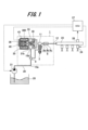
- FIG. 1 is an overall configuration diagram of a fuel supply system using a high-pressure fuel pump according to a first embodiment
- 1 is a vertical sectional view (part 1) of a high-pressure fuel pump according to a first embodiment
- FIG. 1 is a horizontal cross-sectional view of a high-pressure fuel pump according to a first embodiment, as viewed from above
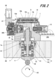
- FIG. 2 is a vertical sectional view (part 2) of the high-pressure fuel pump according to the first embodiment
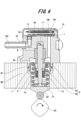
- 2 is an enlarged cross-sectional view showing an electromagnetic valve mechanism of the high-pressure fuel pump according to the first embodiment
- FIG. FIG. 1 is a diagram showing the cavitation generation operation.
- FIG. 1 is a diagram showing the cavitation generation operation.
- 8A and 8B are enlarged views showing the cavitation generation operation.
- FIG. 2 is an enlarged cross-sectional view showing a fixed core and a movable core of the electromagnetic valve mechanism of the high-pressure fuel pump according to the first embodiment
- FIG. 3 is an enlarged cross-sectional view showing the operation of the electromagnetic valve mechanism of the high-pressure fuel pump according to the first embodiment
- FIG. 8 is an enlarged cross-sectional view showing a fixed core and a movable core of an electromagnetic valve mechanism of a high-pressure fuel pump according to a second embodiment.
- FIG. FIG. 13 is a plan view showing a movable core of an electromagnetic valve mechanism of a high-pressure fuel pump according to a third embodiment.
- FIG. 1 is a diagram showing the overall configuration of a fuel supply system using a high-pressure fuel pump according to this embodiment.
- the fuel supply system includes a high-pressure fuel pump 100, an ECU (Engine Control Unit) 27, a fuel tank 20, a common rail 23, and multiple injectors 24.
- the components of the high-pressure fuel pump 100 are integrally assembled into the pump body 1.
- Fuel in the fuel tank 20 is pumped up by a feed pump 21 that is driven based on a signal from the ECU 27.
- the pumped up fuel is pressurized to an appropriate pressure by a pressure regulator (not shown) and sent through a fuel pipe 28 to a low-pressure fuel intake port 10a provided at an intake joint 51 of the high-pressure fuel pump 100.
- the high-pressure fuel pump 100 pressurizes the fuel supplied from the fuel tank 20 and sends it to the common rail 23.
- the common rail 23 is equipped with multiple injectors 24 and a fuel pressure sensor 26.
- the multiple injectors 24 are installed in accordance with the number of cylinders (combustion chambers), and inject fuel according to a drive current output from an ECU 27.
- the fuel supply system of this embodiment is a so-called direct injection engine system in which the injectors 24 inject fuel directly into the cylinders of the engine.
- the fuel pressure sensor 26 outputs the detected pressure data to the ECU 27.
- the ECU 27 calculates the appropriate fuel injection amount (target fuel injection length) and appropriate fuel pressure (target fuel pressure) based on engine state quantities (e.g. crank angle, throttle opening, engine speed, fuel pressure, etc.) obtained from various sensors.
- the ECU 27 also controls the operation of the high-pressure fuel pump 100 and the multiple injectors 24 based on the calculation results of the fuel pressure (target fuel pressure) and the like. That is, the ECU 27 has a pump control unit that controls the high-pressure fuel pump 100 and an injector control unit that controls the injectors 24.
- the high-pressure fuel pump 100 has a plunger 2, a pressure pulsation reduction mechanism 9, a solenoid valve mechanism 300 which is a variable capacity mechanism, a relief valve mechanism 200, and a discharge valve mechanism 8.
- the fuel flowing in from the low-pressure fuel intake port 10a reaches the intake port 31b of the solenoid valve mechanism 300 via the pressure pulsation reduction mechanism 9 and the low-pressure fuel intake passage 10d.
- the fuel that flows into the solenoid valve mechanism 300 passes through the suction valve 30 and flows into the pressurized chamber 11 formed in the pump body 1.
- the pump body 1 holds the plunger 2 in a slidable manner.
- the plunger 2 reciprocates when power is transmitted by the engine cam 93 (see Figure 2).
- One end of the plunger 2 is inserted into the pressurized chamber 11, and increases or decreases the volume of the pressurized chamber 11.
- Fig. 2 is a first longitudinal sectional view of the high-pressure fuel pump 100 taken along a cross section perpendicular to the horizontal direction.
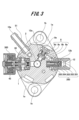
- Fig. 3 is a horizontal sectional view of the high-pressure fuel pump 100 taken along a cross section perpendicular to the vertical direction.
- Fig. 4 is a second longitudinal sectional view of the high-pressure fuel pump 100 taken along a cross section perpendicular to the horizontal direction.
- the pump body 1 of the high-pressure fuel pump 100 is provided with a mounting flange 1a (see Figure 3).
- This mounting flange 1a is in close contact with a fuel pump mounting portion 90 of an engine (internal combustion engine).
- a threaded hole 1b is formed in the flange 1a.
- the pump body 1 is fixed to the fuel pump mounting portion 90 by fastening a number of bolts (screws) (not shown) into the threaded holes 1b formed in the flange 1a.
- an O-ring 61 is interposed between the fuel pump mounting portion 90 and the pump body 1. This O-ring 61 prevents engine oil from leaking between the fuel pump mounting portion 90 and the pump body 1 to the outside of the engine (internal combustion engine).
- a cylinder 6 that guides the reciprocating motion of the plunger 2 is attached to the pump body 1 of the high-pressure fuel pump 100.
- the cylinder 6 is formed in a cylindrical shape, and its outer periphery is press-fitted into the pump body 1.
- the pump body 1 and the cylinder 6 form a pressurizing chamber 11 together with the solenoid valve mechanism 300, the plunger 2, and the discharge valve mechanism 8 (see FIG. 3).
- the pump body 1 has an insertion hole for inserting the cylinder 6 from below.
- the lower end of the insertion hole in the pump body 1 has an inner circumferential convex portion that is deformed inwardly so as to come into contact with the lower surface of the fixing portion 6a provided on the cylinder 6.
- the upper surface of the inner circumferential convex portion of the pump body 1 presses the fixing portion 6a of the cylinder 6 upward in the figure, and the upper end surface of the cylinder 6 seals the pressurized fuel in the pressurized chamber 11 so that it does not leak to the low pressure side.
- a tappet 92 is provided at the lower end of the plunger 2.
- the tappet 92 converts the rotational motion of a cam 93 attached to the engine's camshaft into vertical motion and transmits it to the plunger 2.
- the plunger 2 is biased toward the cam 93 by a spring 4 via a retainer 15, and is pressed against the tappet 92.
- the plunger 2 reciprocates together with the tappet 92, changing the volume of the pressurized chamber 11.
- a seal holder 7 is also disposed between the cylinder 6 and the retainer 15.
- the seal holder 7 is formed in a cylindrical shape into which the plunger 2 is inserted.
- An auxiliary chamber 7a is formed at the upper end of the seal holder 7 on the cylinder 6 side.
- the lower end of the seal holder 7 on the retainer 15 side holds the plunger seal 13.
- the plunger 2 reciprocates up and down.
- the volume of the pressurized chamber 11 expands, and when the plunger 2 ascends, the volume of the pressurized chamber 11 decreases.
- the plunger 2 is arranged to reciprocate in a direction that expands and reduces the volume of the pressurized chamber 11.
- the plunger 2 has a large diameter portion 2a and a small diameter portion 2b.
- the large diameter portion 2a and the small diameter portion 2b are located in the auxiliary chamber 7a. Therefore, the volume of the auxiliary chamber 7a increases and decreases due to the reciprocating motion of the plunger 2.
- the auxiliary chamber 7a is connected to the low-pressure fuel chamber 10.
- fuel flows from the auxiliary chamber 7a to the low-pressure fuel chamber 10, and when the plunger 2 ascends, fuel flows from the low-pressure fuel chamber 10 to the auxiliary chamber 7a. This reduces the amount of fuel flowing into and out of the pump during the intake stroke or return stroke of the high-pressure fuel pump 100, and reduces the pressure pulsation that occurs inside the high-pressure fuel pump 100.
- the pump body 1 is also provided with a relief valve mechanism 200 that communicates with the pressurizing chamber 11.
- the relief valve mechanism 200 has a seat member 201, a relief valve 202, a relief valve holder 203, a relief spring 204, and a spring support member 205.
- the seat member 201 contains the relief spring 204 and forms a relief valve chamber.
- One end of the relief spring 204 abuts against the spring support member 205, and the other end abuts against the relief valve holder 203.
- the relief valve holder 203 engages with the relief valve 202.
- the urging force of the relief spring 204 acts on the relief valve 202 via the relief valve holder 203.
- the relief valve 202 is pressed by the force of the relief spring 204, blocking the fuel passage of the seat member 201.
- the fuel passage of the seat member 201 is connected to the discharge passage 12b (see FIG. 3). The movement of fuel between the pressurized chamber 11 (upstream side) and the seat member 201 (downstream side) is blocked by the relief valve 202 coming into contact (close contact) with the seat member 201.
- the fuel on the seat member 201 side presses against the relief valve 202, moving the relief valve 202 against the biasing force of the relief spring 204.
- the relief valve 202 opens, and the fuel in the discharge passage 12b returns to the pressurized chamber 11 through the fuel passage of the seat member 201. Therefore, the pressure that opens the relief valve 202 is determined by the biasing force of the relief spring 204.
- the relief valve mechanism 200 in this embodiment is connected to the pressurized chamber 11, this is not limited thereto, and it may be connected to, for example, a low pressure passage.
- an intake joint 51 is attached to the side of the pump body 1.
- the intake joint 51 is connected to a fuel pipe 28 through which fuel supplied from the fuel tank 20 passes.
- the fuel in the fuel tank 20 is supplied from the intake joint 51 to the inside of the high-pressure fuel pump 100.
- the intake joint 51 forms the low-pressure fuel intake port 10a.
- the fuel that passes through the intake joint 51 reaches the intake port 31b (see FIG. 5) of the solenoid valve mechanism 300 via the pressure pulsation reduction mechanism 9 provided in the low-pressure fuel chamber 10 and the low-pressure fuel intake passage 10d (see FIG. 2).
- An intake filter 52 is disposed in the fuel passage of the intake joint 51. The intake filter 52 removes foreign matter present between the fuel tank 20 and the low-pressure fuel intake port 10a, preventing foreign matter from entering the high-pressure fuel pump 100.
- the pump body 1 of the high-pressure fuel pump 100 is provided with a low-pressure fuel chamber (damper chamber) 10.
- This low-pressure fuel chamber 10 is covered by a damper cover 14.
- the damper cover 14 is formed, for example, in a cylindrical (cup-shaped) shape with one side closed.
- the low-pressure fuel chamber 10 is divided vertically into an upper damper portion 10b and a lower damper portion 10c by the pressure pulsation reduction mechanism 9.
- the pressure pulsation reduction mechanism 9 is supported from below by a retaining member 9a arranged on the upper end surface of the pump body 1.
- the pressure pulsation reduction mechanism 9 is a metal damper composed of two metal diaphragms stacked on top of each other. Gas of 0.3 MPa to 0.6 MPa is sealed inside the pressure pulsation reduction mechanism 9, and the outer periphery is fixed by welding. For this reason, the outer periphery is thin and is configured to become thicker toward the inner periphery.
- a convex portion is formed on the upper surface of the retaining member 9a for fixing the outer peripheral edge of the pressure pulsation reduction mechanism 9 from below. Meanwhile, a convex portion is formed on the lower surface of the damper cover 14 for fixing the outer peripheral edge of the pressure pulsation reduction mechanism 9 from above.
- These convex portions are formed in a circular shape, and the pressure pulsation reduction mechanism 9 is fixed by being sandwiched between these convex portions.
- the damper cover 14 is fixed by being pressed into the outer peripheral edge of the pump body 1, and at this time the retaining member 9a elastically deforms to support the pressure pulsation reduction mechanism 9.
- the pressure pulsation reduction mechanism 9 divides the low-pressure fuel chamber 10 into an upper damper portion 10b and a lower damper portion 10c.
- a passage is formed in the retaining member 9a that connects the upper and lower sides of the pressure pulsation reduction mechanism 9.
- the suction port 31b is formed in vertical communication with the suction valve seat member 31 that forms the suction valve seat 31a.
- the discharge valve mechanism 8 is connected to the outlet side of the pressurizing chamber 11.
- the discharge valve mechanism 8 includes a discharge valve seat member 8a and a discharge valve 8b that moves toward and away from the discharge valve seat member 8a.
- the discharge valve mechanism 8 also includes a discharge valve spring 8c that biases the discharge valve 8b toward the discharge valve seat member 8a, and a discharge valve stopper 8d that determines the stroke (movement distance) of the discharge valve 8b.
- the discharge valve seat member 8a, discharge valve 8b, discharge valve spring 8c, and discharge valve stopper 8d are housed in a discharge valve chamber 12a formed in the pump body 1.
- the discharge valve chamber 12a is a substantially cylindrical space extending horizontally.
- One end of the discharge valve chamber 12a is connected to the pressurizing chamber 11 via a fuel passage.
- the other end of the discharge valve chamber 12a opens to the side of the pump body 1.
- An abutment portion 8e is formed at the end of the discharge valve stopper 8d.
- the discharge valve chamber 12a and the discharge valve stopper 8d are fixed by welding at the abutment portion 8e. Therefore, the opening at the other end of the discharge valve chamber 12a is sealed by the discharge valve stopper 8d.
- a discharge joint 12 is joined to the pump body 1 by welding.
- the discharge joint 12 has a fuel discharge port.
- the fuel discharge port is connected to the discharge valve chamber 12a via a discharge passage 12b that extends horizontally inside the pump body 1.
- the fuel discharge port of the discharge joint 12 is connected to the common rail 23.
- the discharge valve 8b When the fuel pressure in the pressurized chamber 11 is lower than the fuel pressure in the discharge valve chamber 12a, the discharge valve 8b is pressed against the discharge valve seat member 8a by the differential pressure acting on the discharge valve 8b and the biasing force of the discharge valve spring 8c. As a result, the discharge valve mechanism 8 is in a closed state. On the other hand, when the fuel pressure in the pressurized chamber 11 becomes greater than the fuel pressure in the discharge valve chamber 12a and the differential pressure acting on the discharge valve 8b becomes greater than the biasing force of the discharge valve spring 8c, the discharge valve 8b is pushed by the fuel and moves away from the discharge valve seat member 8a. As a result, the discharge valve mechanism 8 is in an open state.
- the discharge valve mechanism 8 When the discharge valve mechanism 8 opens and closes, fuel is let in and out of the discharge valve chamber 12a. The fuel that leaves the discharge valve chamber 12a is then discharged from the discharge valve mechanism 8 into the discharge passage 12b. As a result, the high-pressure fuel in the pressurized chamber 11 is discharged through the discharge valve chamber 12a, the discharge passage 12b, and the fuel discharge port of the discharge joint 12 into the common rail 23 (see Figure 1). With this configuration, the discharge valve mechanism 8 functions as a check valve that limits the direction of fuel flow.
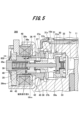
- FIG. 5 is an enlarged cross-sectional view of the solenoid valve mechanism 300.
- the solenoid valve mechanism 300 is inserted into a lateral hole formed in the pump body 1.
- the solenoid valve mechanism 300 includes an intake valve seat member 31 press-fitted into a lateral hole formed in the pump body 1, an intake valve 30 which is an example of a valve body, a stopper 32, an intake valve biasing spring 33, a rod 35, and a movable core 36.
- the solenoid valve mechanism 300 also includes a rod guide 37, an outer core 38, a fixed core 39, a rod biasing spring 40, an anchor biasing spring 41, and an electromagnetic coil (solenoid) 43.
- the suction valve seat member 31 is formed in a cylindrical shape, with a suction valve seat 31a provided on the inner circumference.
- the suction valve seat member 31 is also formed with a suction port 31b that reaches from the outer circumference to the inner circumference. This suction port 31b is connected to the low-pressure fuel suction passage 10d in the low-pressure fuel chamber 10 described above.
- the suction valve seat member 31 is also formed with an opening 31c that opens when the suction valve 30 opens. The fuel passes through the opening 31c and flows into the pressurized chamber 11 via a hole 1c formed laterally in the pump body 1. The hole 1c also constitutes part of the pressurized chamber 11.
- a stopper 32 is disposed in a horizontal hole formed in the pump body 1, facing the suction valve seat 31a of the suction valve seat member 31.
- the suction valve 30 is disposed between the stopper 32 and the suction valve seat 31a.
- a suction valve biasing spring 33 is disposed between the stopper 32 and the suction valve 30. The suction valve biasing spring 33 biases the suction valve 30 toward the suction valve seat 31a.
- the suction valve 30 abuts against the suction valve seat 31a, thereby closing the communication between the suction port 31b and the pressurized chamber 11. This places the solenoid valve mechanism 300 in a closed state.
- the suction valve 30 abuts against the stopper 32, thereby opening the communication between the suction port 31b and the pressurized chamber 11. This places the solenoid valve mechanism 300 in an open state.
- the rod 35 passes through the suction valve seat member 31. One end of the rod 35 abuts against the suction valve 30.
- the rod biasing spring 40 biases the suction valve 30 in the valve opening direction toward the stopper 32 via the rod 35.
- One end of the rod biasing spring 40 engages with a flange portion 35a provided on the outer periphery of the rod 35.
- the other end of the rod biasing spring 40 engages with a fixed core 39 arranged to surround the rod biasing spring 40.
- the fixed core 39 is configured to come into contact with a second yoke 44 that covers an electromagnetic coil chamber in which an electromagnetic coil 43 is arranged.
- the electromagnetic coil 43 is formed by winding a conducting wire around a bobbin 45. Both ends of the conducting wire of the electromagnetic coil 43 are electrically connected to a terminal member 46 (see FIG. 2).
- the terminal member 46 is molded integrally with a connector 47 (see FIG. 2), and the remaining end can be connected to the engine control unit.
- the outer circumference of the electromagnetic coil 43 is surrounded by the first yoke 42, the second yoke 44, and the outer core 38.
- the first yoke 42 and the second yoke 44 are arranged to surround the electromagnetic coil 43.
- the first yoke 42 and the second yoke 44 are then molded and fixed together with a connector, which is a resin member.
- the outer core 38 is pressed into and fixed in a hole in the center of the first yoke 42.
- the outer core 38 is fixed to the pump body 1 by welding or the like.
- the inner diameter side of the second yoke 44 is configured to be in contact with the fixed core 39 or to be adjacent to it with a small clearance.
- the outer diameter side of the second yoke 44 is configured to be in contact with the inner circumference of the first yoke 42 or to be adjacent to it with a small clearance.
- a fixed pin 832 is fixed to the fixed core 39, and generates a biasing force to press the second yoke 44 against the fixed core 39.
- the fixed pin 832 may be inserted into the fixed core 39 at a corner on the inner circumference side, or may be fixed by welding or the like.
- the first yoke 42 and the second yoke 44 are both made of magnetic stainless steel material to form a magnetic circuit and to provide corrosion resistance.
- the bobbin 45 and the connector 47 are made of high-strength, heat-resistant resin to provide strength and heat resistance.
- a seal ring 48 is welded to the outer core 38 on the inner circumference of the electromagnetic coil 43, and its opposite end is welded to the fixed core 39.
- the movable core 36 and rod 35 which are the movable parts, and the rod guide 37, rod biasing spring 40, and anchor biasing spring 41, which are the fixed parts, are arranged.
- the rod 35 is held on the inner circumference side of the rod guide 37 so that it can slide freely in the axial direction, and also holds the movable core 36 so that it can slide freely.
- the movable core 36 faces the end face of the fixed core 39. This movable core 36 engages with a flange portion 35a provided on the outer periphery of the rod 35.
- one end of an anchor biasing spring 41 abuts against the movable core 36 on the side opposite the fixed core 39. The other end of the anchor biasing spring 41 abuts against the rod guide 37.
- the movable core 36 When a current is passed through the electromagnetic coil 43, the movable core 36 is attracted toward the fixed core 39 by the magnetic attraction force that is generated.
- the movable core 36 also has multiple through holes 36a.
- the through holes 36a are formed along the direction of movement of the movable core 36.
- the rod guide 37 has a bearing portion 37b.
- the bearing portion 37b is inserted into the anchor bias spring 41.
- the end of the anchor bias spring 41 abuts against the rod guide 37.
- the rod guide 37 is also provided with a fuel passage 37a, which allows fuel to flow in and out of the space in which the movable core 36 is located.
- the anchor biasing spring 41 also biases the movable core 36 toward the flange portion 35a of the rod 35.
- the amount of movement 36e of the movable core 36 is set to be greater than the amount of movement (valve opening stroke) 30e of the suction valve 30. This allows the suction valve 30 to be reliably abutted (seated) against the suction valve seat 31a, ensuring that the solenoid valve mechanism 300 is in a closed state.
- the solenoid valve mechanism 300 is of a normally open type, which opens in a non-energized state.
- the movable core 36 When the movable core 36 is attracted to the fixed core 39 and moves, the flange portion 35a of the rod 35 engages with the movable core 36, and the rod 35 moves in the valve closing direction together with the movable core 36.
- the suction valve 30 moves in the valve opening direction (away from the suction valve seat 31a) by the amount of the gap of the valve opening stroke 30e, and the valve is opened, and fuel is supplied from the low-pressure fuel suction passage 10d to the pressurized chamber 11.
- the suction valve 30 stops moving when it collides with a stopper 32 that is pressed and fixed inside the housing (rod guide 37) of the solenoid valve mechanism 300.
- the rod 35 and the suction valve 30 are separate and independent structures.
- the suction valve 30 closes the flow path to the pressurized chamber 11 by contacting the suction valve seat 31a of the suction valve seat member 31 arranged on the suction side, and opens the flow path to the pressurized chamber 11 by moving away from the suction valve seat 31a of the suction valve seat member 31.
- the outer core 38 also has an inner circumferential surface against which the outer circumferential surface of the movable core 36 slides.
- the seal ring 48 is made of a material with low hardness (e.g., austenitic stainless steel). This makes it possible to reduce the impact load described below.
- the seal ring 48 is formed to have greater elongation than the fixed core 39 and the movable core 36.
- the seal ring 48 has an elongation rate of, for example, 35% or more.
- the seal ring 48 is also formed of a non-magnetic material (non-magnetic material) for magnetic performance. Specifically, austenitic stainless steel is preferable for the seal ring 48. Austenitic stainless steel is generally non-magnetic and can ensure an elongation rate of 35 to 45% or more.
- the seal ring 48 is formed into a cylinder.
- the fixed core 39 and the outer core 38 have insertion portions 39ins, 38ins that are inserted into the seal ring 48.
- the fixed core 39 and the outer core 38 have outer circumferential surfaces that are flush with the outer circumferential surface CS of the seal ring 48 when inserted into the seal ring 48. This makes it easy to attach other parts, such as the bobbin 45.
- the solenoid valve mechanism 300 As described above, if the solenoid valve mechanism 300 is closed during the compression stroke, the fuel sucked into the pressurized chamber 11 during the intake stroke is pressurized and discharged to the common rail 23. On the other hand, if the solenoid valve mechanism 300 is open during the compression stroke, the fuel in the pressurized chamber 11 is not discharged to the common rail 23. In this way, the discharge of fuel by the high-pressure fuel pump 100 is controlled by opening and closing the solenoid valve mechanism 300. The opening and closing of the solenoid valve mechanism 300 is controlled by the ECU 27.
- the volume of the pressurized chamber 11 increases and the fuel pressure in the pressurized chamber 11 decreases.
- the fuel pressure in the pressurized chamber 11 becomes lower than the pressure in the intake port 31b (see Figure 2), and when the biasing force due to the pressure difference between the two exceeds the biasing force of the intake valve biasing spring 33, the intake valve 30 moves away from the intake valve seat 31a and the solenoid valve mechanism 300 opens. As a result, fuel flows between the intake valve 30 and the intake valve seat 31a and through multiple holes in the stopper 32 into the pressurized chamber 11.
- the high-pressure fuel pump 100 moves to the compression stroke.
- the electromagnetic coil 43 remains in a non-energized state, and no magnetic attraction force acts between the movable core 36 and the fixed core 39.
- the rod biasing spring 40 is set to have a necessary and sufficient biasing force to maintain the intake valve 30 in an open position away from the intake valve seat 31a in the non-energized state.
- the biasing force of the intake valve biasing spring 33 and the fluid force caused by the fuel flowing into the low-pressure fuel intake passage 10d seat the intake valve 30 on the intake valve seat 31a, and the solenoid valve mechanism 300 is in a closed state.
- the fuel in the pressurized chamber 11 is pressurized as the plunger 2 rises, and when the pressure exceeds the pressure at the fuel discharge port, it passes through the discharge valve mechanism 8 and is discharged into the common rail 23 (see Figure 1).
- This stroke is called the discharge stroke.
- the compression stroke from the bottom dead center to the top dead center of the plunger 2 consists of a return stroke and a discharge stroke.
- the amount of high-pressure fuel discharged can be controlled by controlling the timing of energization of the electromagnetic coil 43 of the solenoid valve mechanism 300.
- the timing of energizing the electromagnetic coil 43 If the timing of energizing the electromagnetic coil 43 is advanced, the proportion of the return stroke during the compression stroke will be smaller and the proportion of the discharge stroke will be larger. As a result, less fuel will be returned to the low-pressure fuel intake passage 10d and more fuel will be discharged at high pressure. On the other hand, if the timing of energizing the electromagnetic coil 43 is delayed, the proportion of the return stroke during the compression stroke will be larger and the proportion of the discharge stroke will be smaller. As a result, more fuel will be returned to the low-pressure fuel intake passage 10d and less fuel will be discharged at high pressure. In this way, by controlling the timing of energizing the electromagnetic coil 43, the amount of fuel discharged at high pressure can be controlled to the amount required by the engine (internal combustion engine).
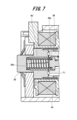
- FIGS. 6 to 8 are diagrams showing the cavitation generation operation.
- the sucked movable core 36 collides with the fixed core 39 and comes into contact with it. Furthermore, as the movable core 36 stops, the flow of fluid into the spring insertion portion 39e of the fixed core 39 also stops. As a result, the fluid in the spring insertion portion 39e of the fixed core 39, which had been under high pressure, flows out from the spring insertion portion 39e toward the through hole 36a of the movable core 36.
- the end of the through hole 36a of the movable core 36 facing the fixed core 39 is in a severe environment for cavitation erosion.
- the collision points of the movable core 36 and the fixed core 39 are hard chrome plated. Therefore, in the conventional technology, in order to apply hard chrome plating, it is necessary to carry out pre-plating and plating, which not only increases the cost of manufacturing the solenoid valve mechanism but also requires labor in manufacturing.
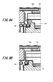
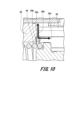
- FIGS. 9 and 10 are enlarged cross-sectional views showing the fixed core 39 and the movable core 36 of the solenoid valve mechanism 300.
- FIG. 9 is enlarged cross-sectional views showing the fixed core 39 and the movable core 36 of the solenoid valve mechanism 300.
- a recess 39b is formed on the collision surface 39a of the fixed core 39 that collides with the movable core 36.
- the recess 39b is formed concentrically with the spring insertion portion 39e at the corner of the spring insertion portion 39e on the collision surface 39a side of the fixed core 39.
- the recess 39b is also located at a position on the collision surface 39a of the fixed core 39 that faces the through hole 36a of the movable core 36, a location where cavitation is likely to occur.
- the recess 39b is an annular recess that is recessed one step from the collision surface 39a in a direction away from the movable core 36.
- FIG. 11 is an enlarged cross-sectional view showing a fixed core and a movable core of the solenoid valve mechanism.
- the solenoid valve mechanism according to the second embodiment has a similar configuration to solenoid valve mechanism 300 according to the first embodiment.
- the solenoid valve mechanism according to the second embodiment differs from solenoid valve mechanism 300 according to the first embodiment in the shape of the recess in the fixed core. Therefore, here, the fixed core will be described, and a description of the configuration common to solenoid valve mechanism 300 according to the first embodiment will be omitted.
- the fixed core 39B has a spring insertion portion 39e into which the rod biasing spring 40 is inserted, a collision surface 39a against which the movable core 36 collides, and a recess 39c.
- the recess 39c is formed in a corner of the spring insertion portion 39e on the collision surface 39a side.
- the recess 39c is disposed in a position on the collision surface 39a of the fixed core 39 facing the through hole 36a of the movable core 36.
- the recess 39c is also formed by chamfering the corner of the spring insertion portion 39e on the collision surface 39a side.
- the volume between the through hole 36a and the collision surface 39a can be increased.
- the pressure fluctuation of the fluid flowing into the through hole 36a can be mitigated by the space formed by the recess 39c.
- the occurrence of cavitation erosion can be suppressed.
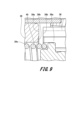
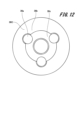
- FIG. 12 is a plan view of the movable core as viewed from the front, that is, from the fixed core side.
- the solenoid valve mechanism according to the third embodiment has a similar configuration to the solenoid valve mechanism 300 according to the first embodiment.
- the solenoid valve mechanism according to the third embodiment differs from the solenoid valve mechanism 300 according to the first embodiment in the shape of the movable core. Therefore, the movable core will be described here, and a description of the configuration common to the solenoid valve mechanism 300 according to the first embodiment will be omitted.
- multiple through holes 36a are formed in the movable core 36C.
- the multiple through holes 36a are formed at approximately equal intervals along the circumferential direction of the movable core 36C.
- a connection recess 36c is formed in the movable core side collision surface 36b of the movable core 36C that abuts against the fixed core 39.
- the connection recess 36c is a recess that is recessed from the movable core side collision surface 36b in a direction away from the fixed core 39.
- the connection recess 36c is formed continuously along the circumferential direction of the movable core 36C, and connects the multiple through holes 36a.
- connection recess 36c makes it possible to increase the volume between the through hole 36a and the collision surface 39a. As a result, when the movable core 36 approaches the fixed core 39B, the pressure fluctuation of the fluid flowing into the through hole 36a can be mitigated by the space formed by the connection recess 36c. As a result, the occurrence of cavitation erosion can be suppressed.
- the fixed core used is either the fixed core 39 in the first embodiment or the fixed core 39B in the second embodiment.
- the recesses 39b, 39c are formed only at the corners of the spring insertion portion 39e and at positions facing the through hole 36a, but this is not limited to the above.
- the recesses may be multiple radial grooves extending from the corners of the spring insertion portion 39e toward the outside in the radial direction of the fixed core, or may have various other shapes.
Landscapes
- Engineering & Computer Science (AREA)
- Chemical & Material Sciences (AREA)
- Combustion & Propulsion (AREA)
- Mechanical Engineering (AREA)
- General Engineering & Computer Science (AREA)
- Fuel-Injection Apparatus (AREA)
Priority Applications (2)
| Application Number | Priority Date | Filing Date | Title |
|---|---|---|---|
| PCT/JP2023/021301 WO2024252603A1 (ja) | 2023-06-08 | 2023-06-08 | 電磁弁機構及び燃料ポンプ |
| JP2025525564A JPWO2024252603A1 (enExample) | 2023-06-08 | 2023-06-08 |
Applications Claiming Priority (1)
| Application Number | Priority Date | Filing Date | Title |
|---|---|---|---|
| PCT/JP2023/021301 WO2024252603A1 (ja) | 2023-06-08 | 2023-06-08 | 電磁弁機構及び燃料ポンプ |
Publications (1)
| Publication Number | Publication Date |
|---|---|
| WO2024252603A1 true WO2024252603A1 (ja) | 2024-12-12 |
Family
ID=93795620
Family Applications (1)
| Application Number | Title | Priority Date | Filing Date |
|---|---|---|---|
| PCT/JP2023/021301 Pending WO2024252603A1 (ja) | 2023-06-08 | 2023-06-08 | 電磁弁機構及び燃料ポンプ |
Country Status (2)
| Country | Link |
|---|---|
| JP (1) | JPWO2024252603A1 (enExample) |
| WO (1) | WO2024252603A1 (enExample) |
Citations (4)
| Publication number | Priority date | Publication date | Assignee | Title |
|---|---|---|---|---|
| JP2003517141A (ja) * | 1999-12-16 | 2003-05-20 | ローベルト ボツシユ ゲゼルシヤフト ミツト ベシユレンクテル ハフツング | 燃料噴射弁 |
| WO2016208359A1 (ja) * | 2015-06-25 | 2016-12-29 | 日立オートモティブシステムズ株式会社 | 流量制御弁及び高圧燃料供給ポンプ |
| JP2019015274A (ja) * | 2017-07-10 | 2019-01-31 | ヤンマー株式会社 | 燃料噴射ポンプ |
| DE102018208909A1 (de) * | 2018-06-06 | 2019-12-12 | Robert Bosch Gmbh | Elektromagnetisch betätigbares Saugventil und Kraftstoff-Hochdruckpumpe |
-
2023
- 2023-06-08 JP JP2025525564A patent/JPWO2024252603A1/ja active Pending
- 2023-06-08 WO PCT/JP2023/021301 patent/WO2024252603A1/ja active Pending
Patent Citations (4)
| Publication number | Priority date | Publication date | Assignee | Title |
|---|---|---|---|---|
| JP2003517141A (ja) * | 1999-12-16 | 2003-05-20 | ローベルト ボツシユ ゲゼルシヤフト ミツト ベシユレンクテル ハフツング | 燃料噴射弁 |
| WO2016208359A1 (ja) * | 2015-06-25 | 2016-12-29 | 日立オートモティブシステムズ株式会社 | 流量制御弁及び高圧燃料供給ポンプ |
| JP2019015274A (ja) * | 2017-07-10 | 2019-01-31 | ヤンマー株式会社 | 燃料噴射ポンプ |
| DE102018208909A1 (de) * | 2018-06-06 | 2019-12-12 | Robert Bosch Gmbh | Elektromagnetisch betätigbares Saugventil und Kraftstoff-Hochdruckpumpe |
Also Published As
| Publication number | Publication date |
|---|---|
| JPWO2024252603A1 (enExample) | 2024-12-12 |
Similar Documents
| Publication | Publication Date | Title |
|---|---|---|
| US11542903B2 (en) | High-pressure fuel supply pump provided with electromagnetic intake valve | |
| JP6689178B2 (ja) | 高圧燃料供給ポンプ | |
| JP7198363B2 (ja) | 電磁吸入弁及び高圧燃料供給ポンプ | |
| US10982638B2 (en) | Device for controlling high-pressure fuel supply pump, and high-pressure fuel supply pump | |
| JP7421646B2 (ja) | 燃料ポンプ | |
| JP7139265B2 (ja) | 高圧燃料供給ポンプ及びリリーフ弁機構 | |
| CN111971470B (zh) | 电磁阀、高压泵以及发动机系统 | |
| US12140113B2 (en) | Electromagnetic valve mechanism and fuel pump | |
| WO2024252603A1 (ja) | 電磁弁機構及び燃料ポンプ | |
| JP7178504B2 (ja) | 燃料ポンプ | |
| WO2019003719A1 (ja) | 高圧燃料供給ポンプ | |
| JP2019167897A (ja) | 燃料供給ポンプ | |
| JP2019100268A (ja) | 燃料供給ポンプ | |
| JP2019090365A (ja) | 燃料供給ポンプ | |
| CN110678642B (zh) | 高压燃料供给泵 | |
| JP7518980B2 (ja) | 燃料ポンプ | |
| JP7024071B2 (ja) | 燃料供給ポンプ | |
| WO2019097990A1 (ja) | リリーフ弁機構およびこれを備えた燃料供給ポンプ | |
| JP7482313B2 (ja) | 燃料ポンプ | |
| CN112243474B (zh) | 电磁阀和高压燃料供给泵 | |
| EP3786442B1 (en) | Fuel supply pump and method for manufacturing fuel supply pump | |
| WO2022269977A1 (ja) | 電磁吸入弁機構及び燃料ポンプ | |
| US20250237186A1 (en) | Electromagnetic Suction Valve and Fuel Supply Pump | |
| JP2019108827A (ja) | 電磁吸入弁及びその電磁吸入弁を備えた燃料供給ポンプ | |
| WO2024084567A1 (ja) | 燃料ポンプ |
Legal Events
| Date | Code | Title | Description |
|---|---|---|---|
| 121 | Ep: the epo has been informed by wipo that ep was designated in this application |
Ref document number: 23940704 Country of ref document: EP Kind code of ref document: A1 |
|
| ENP | Entry into the national phase |
Ref document number: 2025525564 Country of ref document: JP Kind code of ref document: A |
|
| WWE | Wipo information: entry into national phase |
Ref document number: 2025525564 Country of ref document: JP |