WO2024252551A1 - 歯車測定機 - Google Patents
歯車測定機 Download PDFInfo
- Publication number
- WO2024252551A1 WO2024252551A1 PCT/JP2023/021139 JP2023021139W WO2024252551A1 WO 2024252551 A1 WO2024252551 A1 WO 2024252551A1 JP 2023021139 W JP2023021139 W JP 2023021139W WO 2024252551 A1 WO2024252551 A1 WO 2024252551A1
- Authority
- WO
- WIPO (PCT)
- Prior art keywords
- workpiece
- measuring
- measuring device
- gear
- holding device
- Prior art date
- Legal status (The legal status is an assumption and is not a legal conclusion. Google has not performed a legal analysis and makes no representation as to the accuracy of the status listed.)
- Ceased
Links
Images


Classifications
-
- G—PHYSICS
- G01—MEASURING; TESTING
- G01B—MEASURING LENGTH, THICKNESS OR SIMILAR LINEAR DIMENSIONS; MEASURING ANGLES; MEASURING AREAS; MEASURING IRREGULARITIES OF SURFACES OR CONTOURS
- G01B5/00—Measuring arrangements characterised by the use of mechanical techniques
- G01B5/08—Measuring arrangements characterised by the use of mechanical techniques for measuring diameters
Definitions
- the present invention relates to a gear measuring machine.
- Patent Document 1 discloses a configuration in which a gear processing machine is equipped with a gear measuring function.
- Patent Document 2 discloses a configuration in which a gear measuring machine is incorporated into a processing line to perform in-line inspection.
- Patent Documents 1 and 2 do not take into consideration the fact that dust and oil mist generated by gear processing of workpieces on gear processing machines and processing lines can affect the gear measuring machine and reduce measurement accuracy.
- gear measuring machines are usually configured separately from gear processing machines and installed in a measurement room that is outside the processing line and is not affected by dust and oil mist generated on the processing line. In this case, it is necessary to manually carry the processed workpiece into the measurement room and place it on the gear measuring machine to perform measurements, which is time-consuming.
- This disclosure has been made in light of these circumstances, and aims to provide a gear measuring machine that can be installed on a processing line, automates the attachment and detachment of workpieces, and improves measurement accuracy.
- One aspect of the present disclosure is a gear measuring machine provided in a processing line for performing gear processing on a workpiece,
- a workpiece holding device that detachably holds the workpiece; a measuring device for measuring the workpiece by detecting a displacement of a probe brought into contact with the workpiece; a measuring device mounting portion to which the measuring device is attached; a bed supporting the measuring device mounting portion; a cover for collectively covering the workpiece holding device, the measuring device, the measuring device mounting portion, and the bed; the cover has an opening/closing portion that is configured to be opened when the workpiece is attached to the workpiece holding device and removed from the workpiece holding device, and to be closed when the workpiece attached to the workpiece holding device is measured by the measuring device,
- the bed has a moving mechanism for reciprocating the measuring device mounting portion between a retracted position away from the work holding device and a measuring position close to the work holding device, The moving mechanism is configured in a gear measuring machine to move the measuring device mounting portion to the retracted position when the work is held by
- the measuring device mounting section is located in a retracted position when a workpiece is attached or removed, and is located in a measurement position when a workpiece held by the workpiece holding device is measured, so that a conveying device for attaching and removing the workpiece provided on the processing line is prevented from interfering with the measuring device. This makes it possible to automate the attachment and removal of workpieces in the processing line.
- a cover is provided that collectively covers the workpiece holding device, measuring device, measuring device mounting section, and bed, and the cover has an opening and closing section that opens when a workpiece is attached or removed and closes when measuring, so that dust and oil mist generated on the processing line are prevented from entering the gear measuring machine, preventing a decrease in measurement accuracy.
- a gear measuring machine that can be installed on a processing line, can automate the attachment and detachment of workpieces, and can improve measurement accuracy.
- FIG. 1 is a conceptual diagram showing the configuration of a processing line according to the first embodiment.
- FIG. 2 is a partially see-through view of a first side surface of the gear measuring machine of the first embodiment.
- FIG. 3 is a partially see-through view of a second side surface of the gear measuring machine of the first embodiment.
- FIG. 4 is a perspective, partially see-through view of the gear measuring machine of the first embodiment.
- FIG. 5 is a first perspective view of the gear measuring machine of the first embodiment.
- FIG. 6 is a second perspective view of the gear measuring machine of the first embodiment.
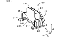
- FIG. 7 is a front perspective view of the measurement device mounting portion according to the first embodiment.
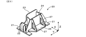
- FIG. 8 is a rear perspective view of the measurement device mounting portion according to the first embodiment.
- FIG. 9 is a top view of the measurement device mounting portion according to the first embodiment.
- FIG. 10 is a vertical cross-sectional view of the workpiece holding device according to the first embodiment with a reference block attached thereto.
- the gear measuring machine 1 of the first embodiment is incorporated in a processing line 100 as shown in FIG. 1.
- the processing line 100 includes a plurality of processing devices 101-103 and the gear measuring machine 1, and the gear measuring machine 1 is provided at the end position of a line L in the processing line 100.
- the direction of movement of the workpiece W in the processing line 100 is L.
- the gear measuring machine 1 may not be disposed at the end position in the processing line 100, but may be disposed at an intermediate position on the line L.
- the processing devices 101-103 are not particularly limited and may be known machine tools.
- the processing line 100 performs gear machining to process and mold the workpiece W, which is the object of processing, into the shape of a gear.
- the gear may be an internal gear or an external gear.
- the processing line 100 multiple processing devices 101 to 103 sequentially process the workpieces W, and the gear measuring machine 1 measures the workpieces W processed by the multiple processing devices 101 to 103. In this way, the processing line 100 continuously processes and measures the workpieces W, and also continuously produces multiple workpieces W.
- the processing line 100 is equipped with a transport device 104 that loads and unloads the workpiece W.
- the transport device 104 may be disposed at each of the processing devices 101-103 and the gear measuring machine 1, or may be disposed across multiple processing devices 101-103 and the gear measuring machine 1.
- the transport device 104 may be, for example, a serial robot type transport device, a loader type transport device, an automated guided vehicle (AGV), or the like.
- the gear measuring machine 1 includes a bed 10, a measuring device mounting section 20, a measuring device 30, a moving mechanism 40, a workpiece holding device 50, a cover 60, and a measurement result transmitting section 70.
- a transport device 104 for loading and unloading the workpiece W into and from the gear measuring machine 1 is provided near the gear measuring machine 1.
- the type of the gear measuring machine 1 is not limited, and it may be a vertical measuring machine that moves a probe vertically to perform measurements, or a horizontal measuring machine that moves a probe horizontally to perform measurements. In this embodiment, a vertical measuring machine is used as described later.
- the front-rear direction parallel to the line L is defined as X
- the vertical direction is defined as Z
- the width direction perpendicular to the X direction and the Z direction is defined as Y.
- the bed 10 constitutes the base of the gear measuring machine 1, has a substantially flat upper surface 11, and is provided with a plurality of legs 12 at the bottom.
- the shape of the bed 10 is not limited, but in this embodiment, the bed 10 is formed by combining metal sheets and is hollow. The hollow portion of the bed 10 may be filled with a filler.
- a recess 13 is formed by recessing the upper surface 11 in an area on the side of the processing device 103 adjacent to the gear measuring machine 1, and a workpiece holding device 50 (described later) is provided therein.
- the measuring device attachment part 20 is provided on the upper surface 11 of the bed 10.
- the measuring device attachment part 20 is also called a slider.
- the measuring device attachment part 20 is capable of reciprocating movement on the upper surface 11 of the bed 10 in the extension direction of the guide rails 41 (in this embodiment, a direction parallel to the line L) via a pair of guide rails 41 constituting a moving mechanism 40 described later.
- the method of determining the shape of the measuring device mounting part 20 is not limited, but in this embodiment, the shape is determined based on the optimized shape obtained by performing topology optimization processing based on the results of stress analysis of the measuring device mounting part 20 based on the elements that vary in the measuring device mounting part 20.
- the elements that vary in the measuring device mounting part 20 are not limited, and examples include temperature changes of the measuring device 30 attached to the measuring device mounting part 20 and the position of the load applied to the measuring device mounting part 20 that varies depending on the position state of the probe in the measuring device 30.
- the measuring device mounting section 20 includes a pair of bases 21 connected to the guide rail 41, and a plurality of side ribs 22 erected in the vertical direction Z on each of the pair of bases 21. Between the side ribs 22 facing each other in the width direction Y, a first central rib 23 and a second central rib 24 are provided, which extend in the width direction Y and the vertical direction Z.
- the first central rib 23 is located on the side (front side) of the processing device 103 adjacent to the gear measuring device 1, and the second central rib 24 is located on the opposite side.
- a flat surface 25 extending in the width direction Y and the front-rear direction X is provided at the lower vertical ends of the first central rib 23 and the second central rib 24.
- the measuring device 30 described later is fixed to the surface of the first central rib 23 on the side (front side) of the processing device 103 adjacent to the gear measuring device 1.
- a back rib 27 erected in the vertical direction Z from the flat surface 25 and extending in the front-rear direction X is connected to the back side of the second central rib 24.
- the end 251 of the planar portion 25 on the side (front side) of the processing device 103 adjacent to the gear measuring device 1 is curved in a wave-like shape with multiple continuous arcs, and has a first through hole 261 with a portion that follows the shape of the end 251 at a position inside (back side) the end 251.
- the planar portion 25 also has a second through hole 262 at a position on the back side of the first through hole 261. Note that a portion of the first central rib 23 overlaps with the first through hole 261 when viewed from above in the vertical direction Z.
- the measuring device 30 includes a probe 31, a probe holding section 32, a first slide base 33, a first guide section 34, a second slide base 35, and a second guide section 36.
- the first guide section 34 extends in the width direction Y
- the first slide base 33 is provided on the first guide section 34 and configured to be movable in the width direction Y.
- the second guide section 36 is provided on the first slide base 33 and extends in the vertical direction Z.
- the second slide base 35 is provided on the second guide section 36 and configured to be movable in the vertical direction Z.
- the probe 31 is substantially rod-shaped and is held by the probe holding section 32.
- the probe holding section 32 is provided on the second slide base 35.
- Moving mechanism 40 The moving mechanism 40 is configured to move the measuring device attachment portion 20 back and forth between a retracted position P1 shown in Fig. 2 and a measuring position P2 shown in Fig. 3.
- the moving mechanism 40 is configured to move the measuring device attachment portion 20 back and forth between a retracted position P1 shown in Fig. 2 and a measuring position P2 shown in Fig. 3.
- the measuring device includes a pair of guide rails 41 provided on the upper surface 11 of the bed 10, and a driving device 42.
- the pair of guide rails 41 are provided on the upper surface 11 of the bed 10 and extend in the front-rear direction X.
- the mounting portion 20 is movable in the front-rear direction X along a pair of guide rails 41 .
- the workpiece holding device 50 includes a workpiece holding section 51 that holds the workpiece W, and a rotation mechanism 52 that rotates the workpiece holding section 51 to a position of an arbitrary rotation angle.
- the workpiece holding section 51 has a plurality of engagement sections 511 that protrude in the vertical direction, and holds the workpiece W by pressing the engagement sections 511 radially outward against the inner cylindrical surface of the workpiece W that constitutes the external gear.
- a cylindrical space 512 with the rotation shaft 50a as its axis is formed inside the plurality of engagement sections 511.
- the workpiece holding section 51 is fixed to a rotation table 521 provided in the rotation mechanism 52.
- the rotation mechanism 52 rotates the disk-shaped rotation table 521 to rotate the workpiece holding section 51 to a position of an arbitrary rotation angle.
- the reference block 53 shown in FIG. 10 When calibrating the work holding device 50, the reference block 53 shown in FIG. 10 is used.
- the reference block 53 is substantially cylindrical, and as shown in FIG. 10, it can be attached to the rotating table 521 via a fixing screw 522 while inserted into the cylindrical space 512 of the work holding section 51.
- the central axis of the inner circumferential surface of the reference block 53 is positioned coaxially with the rotation axis of the rotating table 521.
- the reference block 53 is attached to the rotating table 521 via the cylindrical space 512, and the inner circumferential surface of the opening 531 at the upper end of the reference block 53 is measured with the probe 31, thereby calibrating the center of rotation of the rotating table 521.
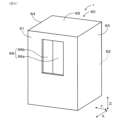
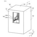
- Cover 60 As shown in Figures 4, 5 and 6, the cover 60 covers the bed 10, the measuring device mounting portion 20, the measuring device 30, the moving mechanism 40 and the workpiece holding device 50 all at once.
- the cover 60 is erected on the floor surface and includes a front wall portion 61, a rear wall portion 62, a right side wall portion 63, a left side wall portion 64 surrounding the above-mentioned components 10 to 50, and a ceiling portion 65 provided at the upper ends of the walls 61 to 64 to cover the upper portions.
- the front wall portion 61 is provided with an opening/closing portion 66.
- the configuration of the opening/closing portion 66 is not limited, in this embodiment, the right door 66a and the left door 66b are configured to move (slide) left and right to open and close. Note that, when the workpiece W is carried in and out from above the workpiece holding device 50, the opening/closing portion 66 may be provided on the ceiling portion 65 instead of the front wall portion 61.
- the opening/closing section 66 is configured to be opened when the workpiece W is attached to the workpiece holding device 50 and removed from the workpiece holding device 50, and to be closed when the workpiece W attached to the workpiece holding device 50 is measured by the measuring device 30.
- the opening and closing operation of the opening/closing section 66 is performed by a drive mechanism (not shown).
- Measurement result transmission unit 70 1 displays the measurement results by the measuring device 30 on a display screen (not shown) of the gear measuring machine 1, or transmits the results to a management device (not shown). Furthermore, the measurement result transmitting unit 70 transmits the measurement results by the measuring device 30 to at least one of the processing devices 101-103 included in the processing line 100.
- the processing devices 101-103 that receive the measurement results can adjust the processing conditions of the processing devices 101-103 in accordance with the measurement results.
- the measuring device mounting portion 20 is located at the retreat position P1 when the workpiece W is attached and detached, and is located at the measurement position P2 when the workpiece W held by the workpiece holding device 50 is measured, so that the conveying device 104 for attaching and detaching the workpiece W provided on the processing line L and the like are prevented from interfering with the measuring device 30. This makes it possible to automate the attachment and detachment of the workpiece W in the processing line L.
- the cover 60 is provided to collectively cover the bed 10, the measuring device 30, the measuring device mounting portion 20, the moving mechanism 40, and the workpiece holding device 50, and the cover 60 is provided with an opening/closing portion 66 that opens when the workpiece W is attached and detached and closes during measurement, thereby suppressing the intrusion of dust and oil mist generated on the processing line L into the gear measuring instrument 1, and preventing a decrease in measurement accuracy.
- the probe 31 is configured to come into contact with the workpiece W by moving vertically downward toward the workpiece W from above the workpiece W in the vertical direction Z when the measuring device mounting portion 20 is located at the measurement position P2.
- the gear measuring machine 1 is a so-called vertical measuring machine, and therefore it is easier to obtain high measurement accuracy compared to a horizontal measuring machine that measures by moving the probe horizontally.
- the probe tilts due to the effects of gravity, and accuracy is particularly poor at the front and rear ends or the left and right ends, but a vertical measuring machine is less susceptible to the effects of gravity and therefore has better accuracy than a horizontal measuring machine.
- the movement mechanism 40 includes a pair of guide rails 41 provided on the upper surface of the bed 10, and a drive device 42 that moves the measurement device mounting part 20 placed on the pair of guide rails 41 back and forth between the retracted position P1 and the measurement position P2 along the pair of guide rails 41. This allows the measurement device mounting part 20 to stably move back and forth between the retracted position P1 and the measurement position P2.
- the bed 10 has a recess 13 recessed downward in the vertical direction Z from the upper surface 11 of the bed 10 at a position vertically Z below the probe 31 when the measuring device mounting part 20 is located at the measurement position P2.
- the work holding device 50 is provided in the recess 13 and has a rotation mechanism 52 that rotates the held work W around an axis in the vertical direction Z. This makes it possible to prevent interference between the transport device 104 and the measuring device 30 when the transport device 104 attaches and detaches the work W to and from the work holding device 50 simply by moving the measuring device mounting part 20 to the retracted position P1, and makes it easy to switch between the retracted position P1 and the measurement position P2.
- the recess 13 is located below the probe 31 in the vertical direction Z when the measuring device mounting part 20 is located at the measurement position P2, and is located between the pair of guide rails 41. This allows the probe 31 to be positioned above the workpiece W in the vertical direction Z with the measuring device 30 being sufficiently supported via the pair of guide rails 41 and the measuring device mounting part 20, improving measurement accuracy.
- the measuring device mounting part 20 is stress analyzed based on the fluctuating factors in the measuring device mounting part 20. Then, topology optimization processing is performed based on the results of the stress analysis.
- the measuring device mounting part 20 has a shape determined based on the optimized shape obtained by the topology optimization processing. This makes it possible to optimize the shape of the measuring device mounting part 20, which has fluctuating factors, with higher precision. For example, one of the fluctuating factors is a change in room temperature inside the factory in which the gear measuring instrument 1 is installed. Since the shape of the measuring device mounting part 20 has a shape determined based on the optimized shape, it is possible to ensure the measurement precision of the gear measuring instrument 1 even if the room temperature inside the factory changes.
- the measuring device mounting part 20 has an end 251 on the front side (workpiece holding device 50 side) of the flat part 25 located vertically Z below the part (first central rib 23) where the measuring device 30 is mounted, which is curved in a wavy shape with multiple arcs continuously, and has a through hole 261 located more inward than the end 251 and having a portion that follows the shape of the end 251. This ensures the rigidity of the measuring device mounting part 20 while reducing its weight.
- the work holding device 50 has a cylindrical space 512 that opens vertically upward on the rotation axis of the work W, and the cylindrical space 512 is configured to allow a reference block 53 to be placed therein for performing positional calibration of the rotation axis 50a of the work W in the work holding device 50.
- the reference block 53 is made of a cylindrical member that is inserted into the cylindrical space 512 and fixed to a rotating table 521, which is a rotating part provided in the work holding device 50, and is configured so that the probe 31 comes into contact with the inner surface of the reference block 53 when performing positional calibration of the rotation axis 50a of the work W. This allows the positional calibration of the rotation axis 50a of the work W to be performed with high accuracy.
- the position of the rotating shaft 50a can be maintained even in a processing line 100 where temperature changes are likely to occur, and the measurement accuracy of the measuring device 30 can be maintained.
- a measurement result transmission unit 70 that transmits the measurement results by the measuring device 30 to at least one of the processing devices 101 to 103 included in the processing line 100. This allows the measurement results by the measuring device 30 to be fed back to the processing devices 101 to 103, thereby improving the processing accuracy of the processing devices 101 to 103.
- a mechanism constituting a tailstock can be used as the workpiece holding device 50 to measure gears formed on a shaft-shaped workpiece W.
- a gear measuring machine that can be installed on a processing line, can automate the attachment and detachment of workpieces, and can improve measurement accuracy.
Landscapes
- Physics & Mathematics (AREA)
- General Physics & Mathematics (AREA)
- Testing Of Devices, Machine Parts, Or Other Structures Thereof (AREA)
Priority Applications (2)
| Application Number | Priority Date | Filing Date | Title |
|---|---|---|---|
| JP2025525519A JPWO2024252551A1 (https=) | 2023-06-07 | 2023-06-07 | |
| PCT/JP2023/021139 WO2024252551A1 (ja) | 2023-06-07 | 2023-06-07 | 歯車測定機 |
Applications Claiming Priority (1)
| Application Number | Priority Date | Filing Date | Title |
|---|---|---|---|
| PCT/JP2023/021139 WO2024252551A1 (ja) | 2023-06-07 | 2023-06-07 | 歯車測定機 |
Publications (1)
| Publication Number | Publication Date |
|---|---|
| WO2024252551A1 true WO2024252551A1 (ja) | 2024-12-12 |
Family
ID=93795591
Family Applications (1)
| Application Number | Title | Priority Date | Filing Date |
|---|---|---|---|
| PCT/JP2023/021139 Ceased WO2024252551A1 (ja) | 2023-06-07 | 2023-06-07 | 歯車測定機 |
Country Status (2)
| Country | Link |
|---|---|
| JP (1) | JPWO2024252551A1 (https=) |
| WO (1) | WO2024252551A1 (https=) |
Citations (6)
| Publication number | Priority date | Publication date | Assignee | Title |
|---|---|---|---|---|
| JPH0634489A (ja) * | 1992-07-14 | 1994-02-08 | Osaka Seimitsu Kikai Kk | ボールマスターギア |
| JPH0814809A (ja) * | 1994-06-29 | 1996-01-19 | Kawasaki Steel Corp | 薄板の表面粗さ測定装置及び方法 |
| JP2005121556A (ja) * | 2003-10-20 | 2005-05-12 | Mitsutoyo Corp | ワーク曲面の測定方法とそのプログラムおよび媒体 |
| CN110889166A (zh) * | 2019-10-30 | 2020-03-17 | 南京理工大学 | 基于热力耦合约束的航空用轴承支架轻量化设计方法 |
| JP2021148770A (ja) * | 2020-03-17 | 2021-09-27 | 株式会社東京精密 | 内面形状測定機の倍率校正方法、及び内面形状測定機 |
| JP2022066416A (ja) * | 2018-03-02 | 2022-04-28 | 株式会社東京精密 | 形状測定装置 |
Family Cites Families (8)
| Publication number | Priority date | Publication date | Assignee | Title |
|---|---|---|---|---|
| JP3132128B2 (ja) * | 1992-03-31 | 2001-02-05 | スズキ株式会社 | ワークの加工装置 |
| JP3072693B2 (ja) * | 1993-06-25 | 2000-07-31 | トヨタ自動車株式会社 | 歯車形状の測定方法 |
| JP3272952B2 (ja) * | 1996-07-02 | 2002-04-08 | キヤノン株式会社 | 3次元形状測定装置 |
| DE102004017172A1 (de) * | 2004-04-02 | 2005-10-20 | Jan Bernd Lugtenburg | Verfahren und Vorrichtung zur Vermessung eines Messobjekts |
| JP5277033B2 (ja) * | 2009-03-25 | 2013-08-28 | 株式会社ミツトヨ | 補正ボール径算出方法および形状測定装置 |
| JP5971902B2 (ja) * | 2011-06-28 | 2016-08-17 | キヤノン株式会社 | ワーク保持装置及び、このワーク保持装置を備えた3次元形状測定装置 |
| JP6001701B2 (ja) * | 2015-01-23 | 2016-10-05 | ファナック株式会社 | ワークに対して作業を即時に行うことが可能なシステム |
| JP7090365B1 (ja) * | 2021-07-30 | 2022-06-24 | 有限会社ピーシー・テクニクス | クランプ装置、固定治具、三次元測定機 |
-
2023
- 2023-06-07 JP JP2025525519A patent/JPWO2024252551A1/ja active Pending
- 2023-06-07 WO PCT/JP2023/021139 patent/WO2024252551A1/ja not_active Ceased
Patent Citations (6)
| Publication number | Priority date | Publication date | Assignee | Title |
|---|---|---|---|---|
| JPH0634489A (ja) * | 1992-07-14 | 1994-02-08 | Osaka Seimitsu Kikai Kk | ボールマスターギア |
| JPH0814809A (ja) * | 1994-06-29 | 1996-01-19 | Kawasaki Steel Corp | 薄板の表面粗さ測定装置及び方法 |
| JP2005121556A (ja) * | 2003-10-20 | 2005-05-12 | Mitsutoyo Corp | ワーク曲面の測定方法とそのプログラムおよび媒体 |
| JP2022066416A (ja) * | 2018-03-02 | 2022-04-28 | 株式会社東京精密 | 形状測定装置 |
| CN110889166A (zh) * | 2019-10-30 | 2020-03-17 | 南京理工大学 | 基于热力耦合约束的航空用轴承支架轻量化设计方法 |
| JP2021148770A (ja) * | 2020-03-17 | 2021-09-27 | 株式会社東京精密 | 内面形状測定機の倍率校正方法、及び内面形状測定機 |
Also Published As
| Publication number | Publication date |
|---|---|
| JPWO2024252551A1 (https=) | 2024-12-12 |
Similar Documents
| Publication | Publication Date | Title |
|---|---|---|
| US8720025B2 (en) | Method for controlling combined lathe apparatus | |
| JP6735149B2 (ja) | 工作機械 | |
| EP2060360B1 (en) | Splash guard for machine tool | |
| TWI495535B (zh) | Machine tool | |
| CN107443145B (zh) | 机床 | |
| EP1795300B1 (en) | Mounting structure for measuring device and grinding machine with the structure | |
| WO2013094367A1 (ja) | 工作機械 | |
| CZ303152B6 (cs) | Zarízení pro manipulaci s obrobky | |
| KR20130129288A (ko) | 림 조립체, 타이어 시험기 및 림 조립체 교환 방법 | |
| WO2024252551A1 (ja) | 歯車測定機 | |
| US20210379709A1 (en) | Machining center and workpiece processing method | |
| JP4274167B2 (ja) | ワーク計測器付き工作機械 | |
| EP0334923B1 (en) | Wide range apparatus for checking linear dimensions of parts | |
| KR101781093B1 (ko) | Cnc 범용 전수검사장치 | |
| KR102397940B1 (ko) | 웨이퍼 반송 로봇 티칭 상태 확인 장치 | |
| JP4044361B2 (ja) | 工具位置検知用センサを付属させたアタッチメント交換装置 | |
| KR101314499B1 (ko) | 공작 기계용 도어 조립체 | |
| JP7568901B2 (ja) | 軌道面研削盤 | |
| JPH09103937A (ja) | 工作機械の工具位置検出装置 | |
| US7866021B2 (en) | Methods and assemblies for manufacturing components | |
| JPH0653913U (ja) | 自動真円度検査装置 | |
| KR20040071823A (ko) | 자동 측정장치의 클램프 | |
| CN117766429A (zh) | 晶圆映射传感器的安装机构 | |
| KR810001929B1 (ko) | 자동 공구검사기를 가진 공작기계조작 장치 | |
| FR2961420A1 (fr) | Procede d'usinage avec compensation de la dilatation de la piece |
Legal Events
| Date | Code | Title | Description |
|---|---|---|---|
| 121 | Ep: the epo has been informed by wipo that ep was designated in this application |
Ref document number: 23940655 Country of ref document: EP Kind code of ref document: A1 |
|
| WWE | Wipo information: entry into national phase |
Ref document number: 2025525519 Country of ref document: JP |
|
| NENP | Non-entry into the national phase |
Ref country code: DE |