WO2024252541A1 - 室内灯制御装置及び室内灯制御方法 - Google Patents
室内灯制御装置及び室内灯制御方法 Download PDFInfo
- Publication number
- WO2024252541A1 WO2024252541A1 PCT/JP2023/021096 JP2023021096W WO2024252541A1 WO 2024252541 A1 WO2024252541 A1 WO 2024252541A1 JP 2023021096 W JP2023021096 W JP 2023021096W WO 2024252541 A1 WO2024252541 A1 WO 2024252541A1
- Authority
- WO
- WIPO (PCT)
- Prior art keywords
- obstacle
- interior light
- driver
- light control
- control device
- Prior art date
- Legal status (The legal status is an assumption and is not a legal conclusion. Google has not performed a legal analysis and makes no representation as to the accuracy of the status listed.)
- Ceased
Links
Images





Classifications
-
- B—PERFORMING OPERATIONS; TRANSPORTING
- B60—VEHICLES IN GENERAL
- B60Q—ARRANGEMENT OF SIGNALLING OR LIGHTING DEVICES, THE MOUNTING OR SUPPORTING THEREOF OR CIRCUITS THEREFOR, FOR VEHICLES IN GENERAL
- B60Q3/00—Arrangement of lighting devices for vehicle interiors; Lighting devices specially adapted for vehicle interiors
- B60Q3/10—Arrangement of lighting devices for vehicle interiors; Lighting devices specially adapted for vehicle interiors for dashboards
- B60Q3/16—Circuits; Control arrangements
- B60Q3/18—Circuits; Control arrangements for varying the light intensity
-
- B—PERFORMING OPERATIONS; TRANSPORTING
- B60—VEHICLES IN GENERAL
- B60Q—ARRANGEMENT OF SIGNALLING OR LIGHTING DEVICES, THE MOUNTING OR SUPPORTING THEREOF OR CIRCUITS THEREFOR, FOR VEHICLES IN GENERAL
- B60Q3/00—Arrangement of lighting devices for vehicle interiors; Lighting devices specially adapted for vehicle interiors
- B60Q3/70—Arrangement of lighting devices for vehicle interiors; Lighting devices specially adapted for vehicle interiors characterised by the purpose
- B60Q3/78—Arrangement of lighting devices for vehicle interiors; Lighting devices specially adapted for vehicle interiors characterised by the purpose for generating luminous strips, e.g. for marking trim component edges
Definitions
- This disclosure relates to an interior light control device and an interior light control method.
- Patent Document 1 only one of the left or right light sources is turned on, based on the direction of the obstacle relative to the vehicle. This causes the problem that the driver can only roughly know the direction in which the obstacle is located, and cannot specifically know the direction of the obstacle and the level of danger. As a result, when the light source is turned on, the driver needs to look for the obstacle while paying a certain amount of attention, which may delay the response to the obstacle.
- the present disclosure has been made in consideration of the above-mentioned problems, and aims to provide technology that can specifically notify the direction and degree of danger of an obstacle.
- the interior light control device is an interior light control device that controls the interior lights of a vehicle, and includes an acquisition unit that acquires obstacle information, which is information about obstacles around the vehicle, and a control unit that determines the direction of the obstacle relative to the driver of the vehicle and the degree of danger of the obstacle based on the obstacle information, and controls the lighting of the parts of the interior lights that correspond to the direction from the driver, among the interior lights that are provided to surround at least the front and sides of the driver continuously or intermittently in a top view, in a manner that has a prominence that corresponds to the degree of danger.
- obstacle information which is information about obstacles around the vehicle
- a control unit determines the direction of the obstacle relative to the driver of the vehicle and the degree of danger of the obstacle based on the obstacle information, and controls the lighting of the parts of the interior lights that correspond to the direction from the driver, among the interior lights that are provided to surround at least the front and sides of the driver continuously or intermittently in a top view, in a manner that has a prominence that corresponds to the degree of danger
- the interior lights which are provided continuously or intermittently surrounding at least the front and sides of the driver in a top view, are controlled to light up the portion of the interior light that corresponds to the direction from the driver in a manner that has a salience that corresponds to the degree of danger.
- this configuration it is possible to specifically notify the driver of the direction and degree of danger of an obstacle.
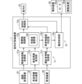
- FIG. 1 is a block diagram showing a configuration of an interior light control device according to a first embodiment
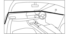
- FIG. 2 is a diagram showing an example of an arrangement of interior lights according to the first embodiment
- FIG. 2 is a top view for explaining the interior light control device according to the first embodiment.
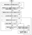
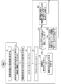
- 4 is a flowchart showing the operation of the interior light control device according to the first embodiment.
- FIG. 11 is a diagram for explaining an interior light control device according to a second embodiment. 10 is a flowchart showing the operation of the interior light control device according to the second embodiment.
- FIG. 10 is a flowchart showing the operation of an interior light control device according to embodiment 4.
- FIG. 13 is a block diagram showing a hardware configuration of an interior light control device according to another modified example.
- FIG. 13 is a block diagram showing a hardware configuration of an interior light control device according to another modified example.
- First embodiment> 1 is a block diagram showing a configuration of an interior light control device 1 according to the present embodiment 1.
- the interior light control device 1 is provided in a vehicle to be controlled by the interior light control device 1, but the present invention is not limited to this and may be provided in, for example, a server capable of wireless communication with the vehicle.
- the interior light control device 1 in FIG. 1 is communicatively connected to a surroundings monitoring device 21, a vehicle information detection device 22, and a vehicle interior light 23, and is capable of controlling the interior light 23.
- a surroundings monitoring device 21, a vehicle information detection device 22, and a vehicle interior light 23 First, before explaining the interior light control device 1, the surroundings monitoring device 21, the vehicle information detection device 22, and the interior light 23 will be explained.
- the surroundings monitoring device 21 detects surrounding information of the vehicle.
- the surroundings information includes obstacle information, which is information about obstacles around the vehicle.
- the obstacle information includes, for example, the direction and distance of the obstacle relative to the vehicle.
- the obstacle information may also include the size of the obstacle.
- the obstacle includes, for example, at least one of a person, another vehicle, and a fallen object.
- the surroundings monitoring device 21 includes, for example, at least one of a distance sensor such as sonar, radar, or Lidar (Light Detection And Ranging), or a camera that captures the surroundings of the vehicle.
- at least one of A, B, C, ..., and Z means any one of all combinations of one or more items selected from the group of A, B, C, ..., and Z.
- the vehicle information detection device 22 detects vehicle information related to the running of the vehicle, such as the steering angle and vehicle speed of the vehicle.
- vehicle information detection device 22 includes, for example, various sensors of the vehicle.
- FIG. 2 is a diagram showing the interior of a vehicle 31 as viewed from the front passenger seat
- FIG. 3 is a top view showing the vehicle 31.
- the interior lights 23 are provided to surround at least the front and sides (e.g., left and right) of the driver 32 of the vehicle 31 continuously or intermittently when viewed from above.
- the interior lights 23 surrounding the driver 32 means that the interior lights 23 are provided over an area larger than the instrument panel.
- the interior lights 23 may surround the front, left side, and right side of the driver 32 as shown in FIG. 3, or may surround the front, left side, right side, and rear of the driver 32.
- the interior light 23 in Figs. 2 and 3 has a line shape, and multiple parts of the line shape can be lit simultaneously.
- the interior light 23 may be composed of, for example, multiple LED arrays arranged in a line shape as multiple segments, each of which can be freely and individually adjusted for brightness, or it may be composed of an LED light chain including multiple LEDs, each of which can be freely and individually adjusted for brightness.
- the interior light 23 in Figs. 2 and 3 is a single continuous light, but may be multiple divided lights.
- the interior light 23 may be, for example, a light for brightening the interior of the vehicle 31, or a light for enhancing the aesthetics of the interior, such as an ambient light or illumination light, or a display device such as an LCD panel or organic EL capable of displaying information.
- the area in which the interior light 23 is provided includes an area corresponding to the blind spot area of the driver 32.
- the area corresponding to the blind spot area includes, for example, the area closest to the blind spot area.
- the blind spot area is an area in which the driver 32 cannot see the outside of the vehicle 31 from the driver's seat, and includes, for example, at least one of the areas of the A-pillar, the hood, and other structures of the vehicle 31.
- the interior light control device 1 in FIG. 1 comprises an obstacle information acquisition unit 11a, a vehicle information acquisition unit 11b, an obstacle recognition unit 12a including a risk level calculation unit 12b, and an interior light control unit 12c.
- the obstacle information acquisition unit 11a and the vehicle information acquisition unit 11b are included in the concept of the acquisition unit 11
- the obstacle recognition unit 12a and the interior light control unit 12c are included in the concept of the control unit 12.
- the obstacle information acquisition unit 11a acquires obstacle information from surrounding information detected by the surroundings monitoring device 21.
- the obstacle information acquisition unit 11a may be an interface to the surroundings monitoring device 21, or may be the surroundings monitoring device 21 itself.
- the vehicle information acquisition unit 11b acquires vehicle information detected by the vehicle information detection device 22.
- the vehicle information acquisition unit 11b may be an interface to the vehicle information detection device 22, or may be the vehicle information detection device 22 itself.
- the obstacle recognition unit 12a determines the direction of the obstacle relative to the driver 32 and the degree of danger of the obstacle based on the obstacle information acquired by the obstacle information acquisition unit 11a and the vehicle information acquired by the vehicle information acquisition unit 11b.
- the obstacle recognition unit 12a may use the direction included in the obstacle information as the direction of the obstacle relative to the driver 32. Also, for example, if the obstacle information includes the direction and distance of the obstacle relative to the vehicle 31, the obstacle recognition unit 12a may calculate the direction of the obstacle relative to the driver 32 based on the direction and distance included in the obstacle information. Note that the direction of the obstacle relative to the driver 32 may be the direction of the obstacle relative to the driver's seat.
- the risk level calculation unit 12b of the obstacle recognition unit 12a determines the distance and type of the obstacle based on the obstacle information and vehicle information, and determines the risk level indicating the possibility of a collision between the vehicle 31 and the obstacle based on the determined distance and type. For example, the risk level calculation unit 12b increases the risk level the shorter the distance, and sets the risk level when the type is a person to be higher than the risk level when the type is a falling object.
- the obstacle recognition unit 12a determines the direction and the degree of danger using both the obstacle information and the vehicle information in order to improve the accuracy of the direction and the degree of danger. However, if there is no need to improve the accuracy of the direction and the degree of danger, the obstacle recognition unit 12a may determine the direction and the degree of danger using the obstacle information without using the vehicle information. In this case, the vehicle information acquisition unit 11b is not essential. The obstacle recognition unit 12a may determine the direction and the degree of danger using the numerical information of the obstacle information as is, or may perform mapping based on the obstacle information and then determine the direction and the degree of danger.
- the interior light control unit 12c controls the lighting of the interior light 23 based on the direction and degree of danger determined by the obstacle recognition unit 12a. Specifically, the interior light control unit 12c controls the lighting of the portion of the interior light 23 that corresponds to the direction from the driver 32 determined by the obstacle recognition unit 12a in a manner that has prominence that corresponds to the degree of danger determined by the obstacle recognition unit 12a.
- the portion of the interior light 23 that corresponds to the above-mentioned direction from the driver 32 may also be referred to as the "obstacle corresponding portion.”
- the obstacle corresponding portion includes at least one of the portion of the interior light 23 located in the direction from the driver 32 determined by the obstacle recognition unit 12a and the surrounding portion. Note that the portion of the interior light 23 that corresponds to the above-mentioned direction from the driver 32 may be the portion of the interior light 23 that corresponds to the above-mentioned direction from the driver's seat.
- the interior light control unit 12c lights up the obstacle corresponding portion of the interior light 23 in a manner that has a conspicuousness that corresponds to the level of danger, with the conspicuousness increasing as the level of danger increases.
- the conspicuousness includes at least one of the following: making the obstacle corresponding portion brighter; increasing the area (e.g., width) of the obstacle corresponding portion; changing the color of the obstacle corresponding portion to a warning color (e.g., red); and, if the obstacle corresponding portion is blinking, shortening the blinking cycle. Note that the conspicuousness is not limited to these, as long as the obstacle corresponding portion is noticeable.
- the obstacle recognition unit 12a and the interior light control unit 12c will be described using Figure 3.
- pedestrians 33a and 33b which are obstacles, are present around the vehicle 31.
- the obstacle recognition unit 12a determines the direction of the pedestrians 33a and 33b relative to the driver 32 and the degree of danger of the pedestrians 33a and 33b. Because the distance between the pedestrian 33a and the vehicle 31 is shorter than the distance between the pedestrian 33b and the vehicle 31, the obstacle recognition unit 12a sets the degree of danger of the pedestrian 33a higher than the degree of danger of the pedestrian 33b.
- the interior light control unit 12c controls the interior light 23 to light up the obstacle corresponding portion 23a corresponding to the direction from the driver 32 to the pedestrian 33a in a manner that has high prominence corresponding to a high level of danger.
- the interior light control unit 12c also controls the interior light 23 to light up the obstacle corresponding portion 23b corresponding to the direction from the driver 32 to the pedestrian 33b in a manner that has low prominence corresponding to a low level of danger.
- the obstacle corresponding portion 23a is lit up in a manner that is more conspicuous than the obstacle corresponding portion 23b by being different from the obstacle corresponding portion 23b in at least one of brightness, area, color, and blinking cycle.
- Fig. 4 is a flowchart showing the operation of the interior light control device 1 according to the embodiment 1. The operation of Fig. 4 is repeatedly performed while the key switch of the vehicle 31 is on or while power is being supplied to the interior light control device 1. Furthermore, when there are a plurality of obstacles, the operation described below is performed for each of the plurality of obstacles.
- step S1 the obstacle information acquisition unit 11a acquires obstacle information, and the vehicle information acquisition unit 11b acquires vehicle information.
- step S2 the obstacle recognition unit 12a determines the direction of the obstacle relative to the driver 32 and the degree of danger of the obstacle based on the obstacle information and vehicle information, and determines whether the degree of danger is equal to or greater than a predetermined threshold. If it is determined that the degree of danger is equal to or greater than the threshold, the process proceeds to step S3, and if it is determined that the degree of danger is less than the threshold, the process returns to step S1.
- step S3 the interior light control unit 12c determines the position and prominence of the obstacle corresponding part based on the direction and degree of danger determined by the obstacle recognition unit 12a.
- step S4 the interior light control unit 12c sends a lighting signal to the interior light 23 indicating the position and prominence of the obstacle corresponding part.
- step S5 the interior light 23 lights up the obstacle-corresponding portion at the position indicated by the lighting signal and in a manner that has the prominence indicated by the lighting signal.
- step S6 the obstacle recognition unit 12a performs the same processing as in steps S1 and S2 to determine whether the danger level is equal to or greater than the threshold. If it is determined that the danger level is equal to or greater than the threshold, the processing returns to step S5, and if it is determined that the danger level is less than the threshold, the processing proceeds to step S7.
- step S7 the interior light control unit 12c stops lighting the obstacle corresponding portion in the above manner. After that, the process returns to step S1.
- the portion of the interior light 23 corresponding to the direction from the driver 32 to the obstacle is turned on in a mode having a saliency corresponding to the degree of danger.
- the driver can specifically know the direction and degree of danger of the obstacle. As a result, for example, the driver can easily find the obstacle and can quickly respond to the obstacle.
- the area in which the interior lights 23 are provided includes an area that corresponds to the blind spot of the driver.
- a block diagram showing the configuration of an interior light control device 1 according to the present embodiment 2 is similar to the block diagram of Fig. 1 described in the embodiment 1.
- components that are the same as or similar to the components described above are given the same or similar reference symbols, and different components will be mainly described.
- the prominence of the obstacle corresponding portion of the interior light 23 is maintained regardless of the time that has passed since the obstacle corresponding portion was turned on.
- the interior light control unit 12c is configured to reduce the prominence of the obstacle corresponding portion as time passes since the obstacle corresponding portion of the interior light 23 was turned on.
- the interior light control unit 12c may relatively increase the area (e.g., width) of the obstacle corresponding portion in order to guide the driver's line of sight, thereby urging the driver to check for the presence of an obstacle.
- the interior light control unit 12c may then reduce the area of the obstacle corresponding portion as time passes from the lighting of the obstacle corresponding portion of the interior light 23, thereby reducing the prominence of the obstacle corresponding portion.
- the interior light control unit 12c may make the obstacle corresponding portion relatively bright in order to guide the driver's line of sight, thereby urging the driver to check for the presence of an obstacle.
- the interior light control unit 12c may then make the obstacle corresponding portion less conspicuous by darkening it as time passes after the obstacle corresponding portion of the interior light 23 is lit.
- the interior light control unit 12c does not need to change the prominence of the obstacle corresponding part linearly with respect to the lighting elapsed time.
- the interior light control unit 12c may change the prominence of the obstacle corresponding part logarithmically with respect to the lighting elapsed time.
- the interior light control unit 12c may momentarily increase the prominence of the obstacle corresponding part as long as the prominence of the obstacle corresponding part is generally decreased as the lighting elapsed time increases.
- the interior light control unit 12c may change the prominence of the obstacle corresponding part discontinuously with respect to time, for example, by lowering the prominence of the obstacle corresponding part to 30% and then increasing the prominence to 60%. In this case, the driver's attention can be drawn to the obstacle.
- the interior light control unit 12c may change the prominence in a stepwise manner with respect to time, instead of changing the prominence with respect to time as shown by the solid line and dotted line in FIG. 5.
- the interior light control unit 12c may be configured to lower the prominence of the obstacle corresponding part as the danger level decreases. With this configuration, when multiple obstacles are present, the driver can prioritize dealing with obstacles whose obstacle corresponding parts are highly conspicuous and therefore of high danger level. Furthermore, when the danger level of an obstacle is equal to or higher than a certain value, the interior light control unit 12c may prohibit lowering of the obstacle corresponding part of that obstacle.
- Fig. 6 is a flowchart showing the operation of the interior light control device 1 according to the embodiment 2.
- the operation of Fig. 6 is similar to the operation of Fig. 4 in that a saliency change process including steps S11a and S11b is added. Therefore, steps S11a and S11b will be mainly described below.
- step S6 If it is determined in step S6 that the risk level is equal to or greater than the threshold, the process proceeds to step S11a, and if it is determined that the risk level is less than the threshold, the process proceeds to step S7.
- step S11a the interior light control unit 12c obtains the time that has elapsed since the lighting in step S5.
- step S11b the interior light control unit 12c compares the acquired time with a logarithmic curve such as that shown in FIG. 5 to determine the amount of attenuation of saliency.
- the interior light control unit 12c then corrects the lighting signal so that the saliency is reduced by the determined amount of attenuation, and transmits the corrected signal to the interior light 23.
- the process proceeds to step S5.
- the saliency of the lighting state of the obstacle corresponding portion is reduced in step S5.
- the saliency of the obstacle corresponding portion of the interior light 23 is reduced as time passes since the obstacle corresponding portion was turned on. With this configuration, the obstacle corresponding portion can be appropriately turned on.
- ⁇ Third embodiment> 7 is a block diagram showing the configuration of an interior light control device 1 according to the present embodiment 3.
- components that are the same as or similar to the components described above are given the same or similar reference numerals, and different components will be mainly described.
- the interior light control device 1 in FIG. 7 is connected to be able to communicate with a monitoring device 24 and an alarm device 25.
- the monitoring device 24 is, for example, a DMS (Driver Monitoring System), which detects the driver's state and generates driver information that is information indicating the driver's state.
- DMS Driver Monitoring System
- the notification device 25 includes a speaker 25a that can notify the driver by voice, and a vibration device 25b that can notify the driver by vibration.
- the notification device 25 is not limited to this, and may be any device that can notify the driver through human senses, and may include, for example, at least one of the speaker 25a, the vibration device 25b, and a display device that can notify the driver by display.
- the configuration of the interior light control device 1 in FIG. 7 is the same as that of the interior light control device 1 in FIG. 1, with the addition of a driver information acquisition unit 11c, an obstacle confirmation determination unit 12d, and a notification control unit 12e.
- the driver information acquisition unit 11c is included in the concept of the acquisition unit 11, and the obstacle confirmation determination unit 12d and the notification control unit 12e are included in the concept of the control unit 12.
- the driver information acquisition unit 11c acquires the driver information generated by the monitoring device 24.
- the driver information acquisition unit 11c may be an interface to the monitoring device 24, or may be the monitoring device 24 itself.
- the obstacle confirmation determination unit 12d determines whether the driver has confirmed an obstacle based on the driver information acquired by the driver information acquisition unit 11c and the direction of the obstacle relative to the driver 32 determined by the obstacle recognition unit 12a. For example, the obstacle confirmation determination unit 12d determines the driver's line of sight based on the driver information, and determines whether the driver has confirmed an obstacle based on whether the direction of the line of sight is substantially the same as the direction of the obstacle relative to the driver 32.
- the interior light control unit 12c reduces the prominence of the obstacle-corresponding portion of the obstacle that has been determined to have been confirmed.
- the notification control unit 12e controls the notification device 25 to notify the driver when the obstacle confirmation determination unit 12d determines that the driver has not confirmed an obstacle even after a predetermined time has elapsed since the obstacle-corresponding portion of the interior light 23 was turned on.
- Fig. 8 is a flowchart showing the operation of the interior light control device 1 according to the third embodiment.
- the operation of Fig. 8 is similar to the operation of Fig. 4 except that step S7 is deleted and steps S31 to S36 are added. Therefore, steps S31 to S36 will be mainly described below.
- step S6 If it is determined in step S6 that the risk level is equal to or greater than the threshold, the process proceeds to step S31; if it is determined that the risk level is less than the threshold, the process proceeds to step S33.
- step S31 the driver information acquisition unit 11c acquires driver information. Then, the obstacle confirmation determination unit 12d determines whether or not the driver has confirmed an obstacle based on the driver information acquired by the driver information acquisition unit 11c and the direction of the obstacle relative to the driver 32 determined by the obstacle recognition unit 12a. If it is determined that the driver has confirmed an obstacle, the process proceeds to step S32, and if it is determined that the driver has not confirmed an obstacle, the process proceeds to step S35.
- step S32 the obstacle recognition unit 12a determines whether the danger level is equal to or greater than a threshold by performing the same processing as in steps S1 and S2.
- the obstacle recognition unit 12a also determines whether the vehicle has taken action to avoid the obstacle based on the obstacle information and the vehicle information. If the danger level is equal to or greater than the threshold and it is determined that the vehicle has not taken action to avoid the obstacle, the process proceeds to step S34; otherwise, the process proceeds to step S33.
- step S33 it has been determined in step S32 that the risk level is below the threshold, or that the vehicle is taking action to avoid an obstacle. Therefore, in step S33, the interior light control unit 12c stops lighting the obstacle corresponding portion in the above manner, and the notification control unit 12e stops the notification from the notification device 25. The process then returns to step S1.
- step S34 it has been determined in step S31 that the driver has at least confirmed the obstacle. Therefore, in step S34, the interior light control unit 12c corrects the lighting signal so as to reduce the prominence of the obstacle-corresponding portion of the obstacle that has been determined to have been confirmed by the driver, and transmits the corrected lighting signal to the interior light 23. After that, the process returns to step S5.
- step S35 the notification control unit 12e determines whether a predetermined time has elapsed since the obstacle corresponding portion of the interior light 23 was turned on. If it is determined that the predetermined time has elapsed, the process proceeds to step S36, and if it is determined that the predetermined time has not elapsed, the process returns to step S5.
- step S36 the notification control unit 12e controls the notification device 25 to notify the driver.
- the interior light control unit 12c may correct the illumination signal and transmit it to the interior light 23 so as to increase the prominence of the obstacle corresponding portion of the obstacle that the obstacle confirmation determination unit 12d has determined not to have been confirmed by the driver. Then, the process returns to step S5.
- control is performed to cause the notification device 25 to notify the driver.
- the monitoring device 24 may not be provided in the third embodiment.
- the notification control unit 12e may control the notification device 25 to notify the driver. Even in this configuration, the driver can be prompted to check for an obstacle.
- the notification device 25 may also include the vehicle's exterior lights. With this configuration, it is possible to highlight the obstacle, thereby informing both the driver and the person who is an obstacle of the dangerous situation and the relative positions of the vehicle and the person who is an obstacle.
- the notification device 25 may also include an instrument panel with a notification function.
- a block diagram showing the configuration of an interior light control device 1 according to the present embodiment 4 is similar to the block diagram of Fig. 1 described in the embodiment 1.
- components that are the same as or similar to the components described above are given the same or similar reference symbols, and different components will be mainly described.
- the interior light control unit 12c is configured to perform control to discontinuously change the state of the obstacle corresponding part of the interior light 23 when at least one of the direction and the danger level of the obstacle to the driver changes continuously.
- the interior light control unit 12c performs control to discontinuously change the state of the obstacle corresponding part of the interior light 23 by changing the blinking cycle of the obstacle corresponding part or changing the lighting color.
- Fig. 9 is a flowchart showing the operation of the interior light control device 1 according to the embodiment 4.
- the operation of Fig. 9 is similar to the operation of Fig. 4 with steps S41 and S42 added. Therefore, steps S41 and S42 will be mainly described below.
- step S6 If it is determined in step S6 that the risk level is equal to or greater than the threshold, the process proceeds to step S41; if it is determined that the risk level is less than the threshold, the process proceeds to step S7.
- step S41 the interior light control unit 12c determines whether or not at least one of the direction and the danger level is continuously changing based on the direction and the danger level of the obstacle determined in step S2 and the direction and the danger level of the obstacle used in the determination in step S6. If it is determined that at least one of the direction and the danger level is continuously changing, the process proceeds to step S42; otherwise, the process proceeds to step S43.
- step S42 the interior light control unit 12c generates a lighting signal for lighting the obstacle corresponding part of the determined obstacle in a discontinuous manner and for causing the obstacle corresponding part to follow the obstacle, and transmits the lighting signal to the interior light 23. Then, the process returns to step S5.
- step S43 the interior light control unit 12c generates a turn-on signal for causing the obstacle-corresponding portion of the undetermined obstacle to follow the obstacle, and transmits the turn-on signal to the interior light 23. Then, the process returns to step S5.
- the interior light control device 1 performs control to discontinuously change the state of the obstacle corresponding part of the interior light 23 when at least one of the direction and the danger of an obstacle to the driver changes continuously.
- the change in the state of the obstacle corresponding part becomes large, so the driver can easily recognize the movement of an obstacle, which changes only slightly. This allows the driver to quickly recognize the danger posed by an obstacle, which changes from moment to moment.
- the acquisition unit 11 and the control unit 12 in FIG. 1 described above will be referred to as "acquisition unit 11, etc.”
- the acquisition unit 11, etc. are realized by a processing circuit 81 shown in FIG. 10. That is, the processing circuit 81 includes an acquisition unit 11 that acquires obstacle information, which is information about obstacles around the vehicle, and a control unit 12 that obtains the direction of the obstacle relative to the driver of the vehicle and the degree of danger of the obstacle based on the obstacle information, and controls the lighting of a portion of the interior light that is provided to surround at least the front and sides of the driver continuously or intermittently in a top view and corresponds to the direction from the driver in a mode having a conspicuousness corresponding to the degree of danger.
- obstacle information which is information about obstacles around the vehicle
- control unit 12 that obtains the direction of the obstacle relative to the driver of the vehicle and the degree of danger of the obstacle based on the obstacle information, and controls the lighting of a portion of the interior light that is provided to surround at least the front and sides of the driver continuously or intermittently in
- the processing circuit 81 may be implemented with dedicated hardware, or may be implemented with a processor that executes a program stored in a memory.
- the processor may be, for example, a central processing unit, a processing unit, an arithmetic unit, a microprocessor, a microcomputer, a DSP (Digital Signal Processor), or the like.
- the processing circuit 81 corresponds to, for example, a single circuit, a composite circuit, a programmed processor, a parallel programmed processor, an ASIC (Application Specific Integrated Circuit), an FPGA (Field Programmable Gate Array), or a combination of these.
- Each function of each unit such as the acquisition unit 11 may be realized by a circuit with distributed processing circuits, or the functions of each unit may be realized together by a single processing circuit.
- the processing circuit 81 When the processing circuit 81 is a processor, the functions of the acquisition unit 11 and the like are realized in combination with software and the like.
- the software and the like includes, for example, software, firmware, or software and firmware.
- the software and the like is written as a program and stored in a memory. As shown in FIG. 11, the processor 82 applied to the processing circuit 81 realizes the functions of each unit by reading and executing a program stored in the memory 83.
- the interior light control device 1 includes a memory 83 for storing a program that, when executed by the processing circuit 81, results in the following steps: acquiring obstacle information, which is information about obstacles around the vehicle; determining the direction of the obstacle with respect to the driver of the vehicle and the degree of danger of the obstacle based on the obstacle information; and controlling the lighting of the part of the interior light that is provided to surround at least the front and sides of the driver continuously or intermittently in a top view and corresponds to the direction from the driver, in a manner having a conspicuousness corresponding to the degree of danger.
- this program can be said to cause a computer to execute the procedures and methods of the acquisition unit 11 and the like.
- memory 83 may be, for example, non-volatile or volatile semiconductor memory such as RAM (Random Access Memory), ROM (Read Only Memory), flash memory, EPROM (Erasable Programmable Read Only Memory), EEPROM (Electrically Erasable Programmable Read Only Memory), HDD (Hard Disk Drive), magnetic disk, flexible disk, optical disk, compact disk, mini disk, DVD (Digital Versatile Disc), drive devices for these, or any storage medium to be used in the future.
- RAM Random Access Memory
- ROM Read Only Memory
- flash memory EPROM (Erasable Programmable Read Only Memory), EEPROM (Electrically Erasable Programmable Read Only Memory), HDD (Hard Disk Drive), magnetic disk, flexible disk, optical disk, compact disk, mini disk, DVD (Digital Versatile Disc), drive devices for these, or any storage medium to be used in the future.
- EPROM Erasable Programmable Read Only Memory
- EEPROM Electrically Erasable Programmable Read Only Memory
- HDD Hard Disk Drive
- magnetic disk
- the above describes a configuration in which the functions of the acquisition unit 11, etc. are realized either by hardware or software, etc.
- this is not limited to the above, and a configuration in which part of the acquisition unit 11, etc. is realized by dedicated hardware and another part is realized by software, etc.
- the function of the acquisition unit 11 can be realized by a processing circuit 81 as dedicated hardware, and the other functions can be realized by the processing circuit 81 as a processor 82 reading and executing a program stored in a memory 83.
- the processing circuit 81 can realize each of the above-mentioned functions through hardware, software, etc., or a combination of these.
Landscapes
- Engineering & Computer Science (AREA)
- Mechanical Engineering (AREA)
- Traffic Control Systems (AREA)
- Arrangements Of Lighting Devices For Vehicle Interiors, Mounting And Supporting Thereof, Circuits Therefore (AREA)
Abstract
障害物の方向及び危険度を具体的に通知可能な技術を提供することを目的とする。車両の室内灯を制御する室内灯制御装置であって、車両の周囲の障害物の情報である障害物情報を取得する取得部と、障害物情報に基づいて、車両の運転者に対する障害物の方向と、障害物の危険度とを求め、上面視にて少なくとも運転者の前方及び側方を連続的にまたは断続的に囲んで設けられた室内灯のうち運転者からの方向に対応する部分を、危険度に対応する顕著性を有する態様で点灯する制御を行う制御部とを備える。
Description
本開示は、室内灯制御装置及び室内灯制御方法に関する。
車両周辺の障害物を検知した場合に、前照灯または補助灯(以下、これらをまとめて「車外灯」と記す)で障害物に投光することによって、車両の運転者に障害物を知らせる技術が知られている。しかしながら、太陽光が存在する昼間のように車両の周囲が明るい環境下では、運転者は車外灯そのものを確認できないという問題がある。そこで、車外灯ではなく、車両室内のインストルメントパネルの左右に設けられた光源を用いて、運転者に障害物を知らせる技術が提案されている(例えば特許文献1)。
しかしながら特許文献1の技術では、車両に対する障害物の方向に基づいて、左右の光源のいずれか1つしか点灯しない。このため、運転者は、障害物が存在する方向を大まかにしか知ることができず、障害物の方向及び危険度を具体的に知ることができないという問題がある。この結果として、光源の点灯時に、運転者は一定の注意を払いながら障害物を探す必要があるため、障害物への対応が遅れてしまう可能性がある。
そこで、本開示は、上記のような問題点に鑑みてなされたものであり、障害物の方向及び危険度を具体的に通知可能な技術を提供することを目的とする。
本開示に係る室内灯制御装置は、車両の室内灯を制御する室内灯制御装置であって、車両の周囲の障害物の情報である障害物情報を取得する取得部と、障害物情報に基づいて、車両の運転者に対する障害物の方向と、障害物の危険度とを求め、上面視にて少なくとも運転者の前方及び側方を連続的にまたは断続的に囲んで設けられた室内灯のうち運転者からの方向に対応する部分を、危険度に対応する顕著性を有する態様で点灯する制御を行う制御部とを備える。
本開示によれば、上面視にて少なくとも運転者の前方及び側方を連続的にまたは断続的に囲んで設けられた室内灯のうち運転者からの方向に対応する部分を、危険度に対応する顕著性を有する態様で点灯する制御を行う。このような構成によれば、障害物の方向及び危険度を具体的に通知することができる。
本開示の目的、特徴、局面及び利点は、以下の詳細な説明と添付図面とによって、より明白となる。
<実施の形態1>
図1は、本実施の形態1に係る室内灯制御装置1の構成を示すブロック図である。本実施の形態1では、室内灯制御装置1は、室内灯制御装置1の制御対象となる車両に設けられているが、これに限ったものではなく、例えば車両と無線通信が可能なサーバに設けられてもよい。
図1は、本実施の形態1に係る室内灯制御装置1の構成を示すブロック図である。本実施の形態1では、室内灯制御装置1は、室内灯制御装置1の制御対象となる車両に設けられているが、これに限ったものではなく、例えば車両と無線通信が可能なサーバに設けられてもよい。
図1の室内灯制御装置1は、周囲監視装置21と、車両情報検出装置22と、車両の室内灯23と通信可能に接続されており、室内灯23を制御可能になっている。まず、室内灯制御装置1について説明する前に、周囲監視装置21、車両情報検出装置22、及び、室内灯23について説明する。
周囲監視装置21は、車両の周囲情報を検出する。周囲情報は、車両の周囲の障害物の情報である障害物情報を含む。障害物情報は、例えば車両に対する障害物の方向及び距離を含む。また障害物情報は、障害物の大きさを含んでもよい。障害物は、例えば、人、他車両、及び、落下物の少なくともいずれか1つを含む。周囲監視装置21は、例えば、ソナー、レーダー、もしくはLidar(Light Detection And Ranging)などの距離センサ、または、車両の周囲を撮影するカメラなどの少なくともいずれか1つを含む。なお本明細書において、例えばA、B、C、…、及び、Zの少なくともいずれか1つとは、A、B、C、…、及び、Zのグループから1つ以上抜き出した全ての組合せのうちのいずれか1つであることを意味する。
車両情報検出装置22は、車両のハンドル角及び車速などの車両の走行に関する車両情報を検出する。車両情報検出装置22は、例えば、車両の各種センサを含む。
図2は、車両31の助手席付近から前方をみたときの車両の室内を示す図であり、図3は、車両31を模式的に示す上面図である。図2及び図3に示すように、室内灯23は、上面視にて少なくとも車両31の運転者32の前方及び側方(例えば左右)を連続的にまたは断続的に囲んで設けられている。なお、室内灯23が運転者32を囲むことは、室内灯23がインストルメントパネルよりも大きな範囲に亘って設けられていることを意味する。室内灯23が運転者32を囲むことの例として、室内灯23は、図3のように運転者32の前方、左側方、及び、右側方を囲んでもよいし、運転者32の前方、左側方、右側方、及び、後方を囲んでもよい。
図2及び図3の室内灯23は、ライン形状を有しており、当該ライン形状のうちの複数の部分を同時に点灯可能である。室内灯23は、例えばライン形状に複数のセグメントとして並べられ、それぞれが自在かつ個別に調光可能な複数のLEDアレイから構成されてもよいし、それぞれが自在かつ個別に調光可能な複数のLEDを含むLEDライトチェーンから構成されてもよい。
図2及び図3の室内灯23は、連続した一つのライトであるが、分割された複数のライトであってもよい。室内灯23は、例えば、車両31の室内を明るくするためのライトであってもよいし、アンビエントライト及びイルミネーションライトなどの室内の美観を高めるためのライトであってもよいし、情報を表示可能な液晶パネル及び有機ELなどのディスプレイデバイスでもよい。
本実施の形態1では、室内灯23が設けられた領域は、運転者32の死角領域に対応する領域を含む。死角領域に対応する領域は、例えば死角領域に最も近い領域を含む。死角領域は、運転者32が運転席から車両31の外部を見ることができない領域であり、例えば、車両31のAピラーの領域、ボンネットの領域、その他の構造物の領域の少なくともいずれか1つを含む。
次に、室内灯制御装置1の構成について説明する。図1の室内灯制御装置1は、障害物情報取得部11aと、車両情報取得部11bと、危険度演算部12bを含む障害物認識部12aと、室内灯制御部12cとを備える。なお、障害物情報取得部11a及び車両情報取得部11bは取得部11の概念に含まれ、障害物認識部12a及び室内灯制御部12cは制御部12の概念に含まれる。
障害物情報取得部11aは、周囲監視装置21で検出された周囲情報から障害物情報を取得する。障害物情報取得部11aは、周囲監視装置21のインタフェースであってもよいし、周囲監視装置21そのものであってもよい。
車両情報取得部11bは、車両情報検出装置22で検出された車両情報を取得する。車両情報取得部11bは、車両情報検出装置22のインタフェースであってもよいし、車両情報検出装置22そのものであってもよい。
障害物認識部12aは、障害物情報取得部11aで取得された障害物情報と、車両情報取得部11bで取得された車両情報とに基づいて、運転者32に対する障害物の方向と、障害物の危険度とを求める。
例えば、障害物情報が車両31に対する障害物の方向を含む場合に、障害物認識部12aは、障害物情報に含まれる方向を、運転者32に対する障害物の方向として用いてもよい。また例えば、障害物情報が車両31に対する障害物の方向及び距離を含む場合には、障害物認識部12aは、障害物情報に含まれる方向及び距離に基づいて、運転者32に対する障害物の方向を算出してもよい。なお、運転者32に対する障害物の方向は、運転席に対する障害物の方向であってもよい。
障害物認識部12aの危険度演算部12bは、障害物情報と車両情報とに基づいて、障害物の距離及び種別などを求め、求めた距離及び種別に基づいて、車両31と障害物とが衝突とする可能性を示す危険度を求める。例えば、危険度演算部12bは、距離が小さいほど危険度を高くし、種別が人である場合の危険度を種別が落下物である場合の危険度よりも高くする。
なお本実施の形態1では、障害物認識部12aは、方向及び危険度の精度を高めるために、障害物情報及び車両情報の両方を用いて方向及び危険度を求めている。しかしながら、方向及び危険度の精度を高める必要がない場合には、障害物認識部12aは、車両情報を用いずに障害物情報を用いて方向及び危険度を求めてもよい。この場合、車両情報取得部11bは必須ではない。また、障害物認識部12aは、障害物情報の数値情報をそのまま用いて方向及び危険度を求めてもよいし、障害物情報に基づいてマッピングを実施してから方向及び危険度を求めてもよい。
室内灯制御部12cは、障害物認識部12aで求めた方向及び危険度に基づいて室内灯23の点灯制御を行う。具体的には、室内灯制御部12cは、室内灯23のうち、運転者32からの障害物認識部12aで求めた方向に対応する部分を、障害物認識部12aで求めた危険度に対応する顕著性を有する態様で点灯する制御を行う。なお、以下の説明では、室内灯23のうち、運転者32からの上記方向に対応する部分を、「障害物対応部分」と記すこともある。
障害物対応部分は、室内灯23のうち運転者32から障害物認識部12aで求めた方向に位置する部分、及び、その周辺の部分の少なくともいずれか1つを含む。なお、室内灯23のうち、運転者32からの上記方向に対応する部分は、室内灯23のうち、運転席からの上記方向に対応する部分であってもよい。
室内灯制御部12cは、危険度に対応する顕著性を有する態様として、危険度が高いほど顕著性が高い態様で、室内灯23の障害物対応部分を点灯する。顕著性が高い態様は、障害物対応部分を明るくする態様と、障害物対応部分の面積(例えば幅)を大きくする態様と、障害物対応部分の色を警戒色(例えば赤色)にする態様と、障害物対応部分を点滅する場合には点滅周期を短くする態様との少なくともいずれか1つを含む。なお、顕著性が高い態様は、障害物対応部分が目立つ態様であれば、これらに限ったものではない。
図3を用いて、障害物認識部12a及び室内灯制御部12cについて説明する。図3には、車両31の周辺に、障害物である歩行者33a,33bが存在している。この場合、障害物認識部12aは、運転者32に対する歩行者33a、33bの方向と、歩行者33a,33bの危険度とを求める。歩行者33aと車両31との間の距離は、歩行者33bと車両31との間の距離よりも小さいため、障害物認識部12aは、歩行者33aの危険度を歩行者33bの危険度よりも高く設定する。
室内灯制御部12cは、室内灯23のうち運転者32から歩行者33aへの方向に対応する障害物対応部分23aを、高い危険度に対応する高い顕著性を有する態様で点灯する制御を行う。また、室内灯制御部12cは、室内灯23のうち運転者32から歩行者33bへの方向に対応する障害物対応部分23bを、低い危険度に対応する低い顕著性を有する態様で点灯する制御を行う。この結果、障害物対応部分23aは、障害物対応部分23bと明るさ、面積、色、及び、点滅周期の少なくともいずれかが異なることによって、障害物対応部分23bよりも目立つ態様で点灯される。
<動作>
図4は、本実施の形態1に係る室内灯制御装置1の動作を示すフローチャートである。図4の動作は、車両31のキースイッチがオンまたは室内灯制御装置1に電源が供給されている間に繰り返し行われる。また、障害物の数が複数である場合には、以下で説明する動作は複数の障害物のそれぞれについて行われる。
図4は、本実施の形態1に係る室内灯制御装置1の動作を示すフローチャートである。図4の動作は、車両31のキースイッチがオンまたは室内灯制御装置1に電源が供給されている間に繰り返し行われる。また、障害物の数が複数である場合には、以下で説明する動作は複数の障害物のそれぞれについて行われる。
ステップS1にて、障害物情報取得部11aは障害物情報を取得し、車両情報取得部11bは車両情報を取得する。
ステップS2にて、障害物認識部12aは、障害物情報及び車両情報に基づいて、運転者32に対する障害物の方向と、障害物の危険度とを求め、危険度が予め定められた閾値以上であるか否かを判定する。危険度が閾値以上であると判定された場合には処理がステップS3に進み、危険度が閾値未満であると判定された場合には処理がステップS1に戻る。
ステップS3にて、室内灯制御部12cは、障害物認識部12aで求められた方向及び危険度に基づいて、障害物対応部分の位置及び顕著性を求める。
ステップS4にて、室内灯制御部12cは、障害物対応部分の位置及び顕著性を示す点灯信号を室内灯23に送信する。
ステップS5にて、室内灯23は、点灯信号で示される位置に、点灯信号で示される顕著性を有する態様で障害物対応部分を点灯する。
ステップS6にて、ステップS1及びステップS2と同様の処理を行うことによって、障害物認識部12aは、危険度が閾値以上であるか否かを判定する。危険度が閾値以上であると判定された場合には処理がステップS5に戻り、危険度が閾値未満であると判定された場合には処理がステップS7に進む。
ステップS7にて、室内灯制御部12cは、障害物対応部分を上記態様で点灯することを停止する。その後、処理がステップS1に戻る。
<実施の形態1のまとめ>
以上のような本実施の形態1に係る室内灯制御装置1によれば、室内灯23のうち運転者32から障害物への方向に対応する部分を、危険度に対応する顕著性を有する態様で点灯する。このような構成によれば、運転者は障害物の方向及び危険度を具体的に知ることができる。この結果、例えば運転者は障害物を容易に探すことができ、障害物に素早く対応することができる。
以上のような本実施の形態1に係る室内灯制御装置1によれば、室内灯23のうち運転者32から障害物への方向に対応する部分を、危険度に対応する顕著性を有する態様で点灯する。このような構成によれば、運転者は障害物の方向及び危険度を具体的に知ることができる。この結果、例えば運転者は障害物を容易に探すことができ、障害物に素早く対応することができる。
また本実施の形態1では、室内灯23が設けられた領域は、運転者の死角領域に対応する領域を含む。このような構成によれば、運転者はAピラーなどによる死角領域に障害物がある場合であっても、運転者は、障害物の存在を確認することができるので、慎重な運転を行うことができる。
<実施の形態2>
本実施の形態2に係る室内灯制御装置1の構成を示すブロック図は、実施の形態1で説明した図1のブロック図と同様である。以下、本実施の形態2に係る構成要素のうち、上述の構成要素と同じまたは類似する構成要素については同じまたは類似する参照符号を付し、異なる構成要素について主に説明する。
本実施の形態2に係る室内灯制御装置1の構成を示すブロック図は、実施の形態1で説明した図1のブロック図と同様である。以下、本実施の形態2に係る構成要素のうち、上述の構成要素と同じまたは類似する構成要素については同じまたは類似する参照符号を付し、異なる構成要素について主に説明する。
実施の形態1では、室内灯23の障害物対応部分の点灯から経過した時間に関わらず、障害物対応部分の顕著性が維持される。これに対して本実施の形態2では、室内灯制御部12cは、室内灯23の障害物対応部分の点灯から時間が経過するにつれて、障害物対応部分の顕著性を低くするように構成されている。
例えば、室内灯制御部12cは、障害物対応部分の点灯初期には、運転者の視線を誘導するために、障害物対応部分の面積(例えば幅)を比較的大きくすることによって、運転者が障害物の存在を確認するように運転者に促してもよい。そして、室内灯制御部12cは、室内灯23の障害物対応部分の点灯から時間が経過するにつれて障害物対応部分の面積を小さくすることによって、障害物対応部分の顕著性を低くしてもよい。このような構成によれば、運転者から見た2つの障害物同士の距離が狭い場合でも、2つの障害物についての障害物対応部分を離間して点灯することができる。
また例えば、室内灯制御部12cは、障害物対応部分の点灯初期には、運転者の視線を誘導するために、障害物対応部分の明るさを比較的明るくすることによって、運転者が障害物の存在を確認するように運転者に促してもよい。そして、室内灯制御部12cは、室内灯23の障害物対応部分の点灯から時間が経過するにつれて障害物対応部分を暗くすることによって、障害物対応部分の顕著性を低くしてもよい。このような構成によれば、夜間の障害物対応部分の逆光による運転者の幻惑を抑制することができるため、運転者は障害物を容易に確認することができる。
なお、室内灯制御部12cは、障害物対応部分の顕著性を、点灯経過時間に対して直線的に変化させる必要はない。例えば図5の実線に示すように、室内灯制御部12cは、障害物対応部分の顕著性を、点灯経過時間に対して対数曲線的に変化させてもよい。また例えば、室内灯制御部12cは、概ね、点灯経過時間が大きくなるにつれて障害物対応部分の顕著性を低くするのであれば、障害物対応部分の顕著性を瞬間的に高くしてもよい。つまり、図5の実線及び点線に示すように、室内灯制御部12cは、障害物対応部分の顕著性を例えば30%まで下げた後に、当該顕著性を例えば60%まで上げるなどして、時間に対して不連続に変化させてもよい。この場合には、運転者の注意を障害物に惹くことができる。また、室内灯制御部12cは、時間に対して図5の実線及び点線のように顕著性を変化させるのではなく、時間に対して階段状に顕著性を変化させてもよい。
なお、室内灯制御部12cは、危険度が低下するにつれて障害物対応部分の顕著性を低くするように構成されてもよい。このような構成によれば、複数の障害物が存在する場合に、障害物対応部分の顕著性が高くて危険度が高い障害物に対して運転者は優先的に対処することができる。また、室内灯制御部12cは、障害物の危険度が一定値以上である場合には、当該障害物の障害物対応部分の低下を禁止してもよい。
<動作>
図6は、本実施の形態2に係る室内灯制御装置1の動作を示すフローチャートである。図6の動作は、図4の動作に、ステップS11a,S11bを含む顕著性変更処理が追加された構成と同様である。このため、以下ではステップS11a,S11bについて主に説明する。
図6は、本実施の形態2に係る室内灯制御装置1の動作を示すフローチャートである。図6の動作は、図4の動作に、ステップS11a,S11bを含む顕著性変更処理が追加された構成と同様である。このため、以下ではステップS11a,S11bについて主に説明する。
ステップS6にて、危険度が閾値以上であると判定された場合には処理がステップS11aに進み、危険度が閾値未満であると判定された場合には処理がステップS7に進む。
ステップS11aにて、室内灯制御部12cは、ステップS5の点灯から経過した時間を取得する。
ステップS11bにて、室内灯制御部12cは、取得した時間について図5などの対数曲線を照合して、顕著性の減衰量を求める。そして、室内灯制御部12cは、求めた減衰量で顕著性が低下するように点灯信号を補正して室内灯23に送信する。その後、処理がステップS5に進む。これにより、ステップS5にて障害物対応部分の点灯態様の顕著性が低下する。
<実施の形態2のまとめ>
以上のような本実施の形態2に係る室内灯制御装置1によれば、室内灯23の障害物対応部分の点灯から時間が経過するにつれて、障害物対応部分の顕著性を低くする。このような構成によれば、障害物対応部分を適切に点灯することができる。
以上のような本実施の形態2に係る室内灯制御装置1によれば、室内灯23の障害物対応部分の点灯から時間が経過するにつれて、障害物対応部分の顕著性を低くする。このような構成によれば、障害物対応部分を適切に点灯することができる。
<実施の形態3>
図7は、本実施の形態3に係る室内灯制御装置1の構成を示すブロック図である。以下、本実施の形態3に係る構成要素のうち、上述の構成要素と同じまたは類似する構成要素については同じまたは類似する参照符号を付し、異なる構成要素について主に説明する。
図7は、本実施の形態3に係る室内灯制御装置1の構成を示すブロック図である。以下、本実施の形態3に係る構成要素のうち、上述の構成要素と同じまたは類似する構成要素については同じまたは類似する参照符号を付し、異なる構成要素について主に説明する。
図7の室内灯制御装置1は、監視装置24と、報知装置25と通信可能に接続されている。監視装置24は、例えばDMS(Driver Monitoring System)であり、運転者の状態を検知して、運転者の状態を示す情報である運転者情報を生成する。
報知装置25は、運転者に音声で報知可能なスピーカ25aと、運転者に振動で報知可能な振動装置25bとを含む。なお、報知装置25は、これに限ったものではなく、人間の感覚などに対して報知可能な装置であればよく、例えば、スピーカ25aと、振動装置25bと、運転者に表示で報知可能な表示装置との少なくともいずれか1つを含んでもよい。
図7の室内灯制御装置1の構成は、図1の室内灯制御装置1の構成に、運転者情報取得部11cと、障害物確認判定部12dと、報知制御部12eとが追加された構成と同様である。運転者情報取得部11cは取得部11の概念に含まれ、障害物確認判定部12d及び報知制御部12eは制御部12の概念に含まれる。
運転者情報取得部11cは、監視装置24で生成された運転者情報を取得する。運転者情報取得部11cは、監視装置24のインタフェースであってもよいし、監視装置24そのものであってもよい。
障害物確認判定部12dは、運転者情報取得部11cで取得された運転者情報と、障害物認識部12aで求めた運転者32に対する障害物の方向とに基づいて、運転者が障害物を確認したか否かを判定する。例えば、障害物確認判定部12dは、運転者情報に基づいて運転者の視線を求め、当該視線の方向が、運転者32に対する障害物の方向と実質的に同じであるか否かに基づいて、運転者が障害物を確認したか否かを判定する。
室内灯制御部12cは、障害物確認判定部12dで運転者が障害物を確認したと判定された場合に、確認したと判定された障害物についての障害物対応部分の顕著性を低くする。
報知制御部12eは、室内灯23の障害物対応部分の点灯から予め定められた時間が経過しても、障害物確認判定部12dによって運転者が障害物を確認しないと判定された場合に、運転者への報知を報知装置25にさせる制御を行う。
<動作>
図8は、本実施の形態3に係る室内灯制御装置1の動作を示すフローチャートである。図8の動作は、図4の動作にステップS7が削除され、ステップS31~S36が追加された構成と同様である。このため、以下ではステップS31~S36について主に説明する。
図8は、本実施の形態3に係る室内灯制御装置1の動作を示すフローチャートである。図8の動作は、図4の動作にステップS7が削除され、ステップS31~S36が追加された構成と同様である。このため、以下ではステップS31~S36について主に説明する。
ステップS6にて、危険度が閾値以上であると判定された場合には処理がステップS31に進み、危険度が閾値未満であると判定された場合には処理がステップS33に進む。
ステップS31にて、運転者情報取得部11cは運転者情報を取得する。そして、障害物確認判定部12dは、運転者情報取得部11cで取得された運転者情報と、障害物認識部12aで求めた運転者32に対する障害物の方向とに基づいて、運転者が障害物を確認したか否かを判定する。運転者が障害物を確認したと判定された場合には処理がステップS32に進み、運転者が障害物を確認しなかったと判定された場合には処理がステップS35に進む。
ステップS32にて、ステップS1及びステップS2と同様の処理を行うことによって、障害物認識部12aは、危険度が閾値以上であるか否かを判定する。また、障害物認識部12aは、障害物情報と車両情報とに基づいて車両が障害物を回避する行動を実施したか否かを判定する。危険度が閾値以上であり、かつ、車両が障害物を回避する行動を実施していないと判定された場合には処理がステップS34に進み、そうでない場合には処理がステップS33に進む。
ステップS33に進んだ場合には、ステップS32にて危険度が閾値未満である、または、車両が障害物を回避する行動を実施していると判定されている。そのためステップS33にて、室内灯制御部12cは、障害物対応部分を上記態様で点灯することを停止し、報知制御部12eは、報知装置25の報知を停止する。その後、処理がステップS1に戻る。
ステップS34に進んだ場合には、ステップS31にて運転者は障害物を一応確認していると判定されている。そのためステップS34にて、室内灯制御部12cは、運転者が確認したと判定された障害物についての障害物対応部分の顕著性が低下するように点灯信号を補正して室内灯23に送信する。その後、処理がステップS5に戻る。
ステップS35にて、報知制御部12eは、室内灯23の障害物対応部分の点灯から予め定められた時間が経過したか否かを判定する。予め定められた時間が経過したと判定した場合には処理がステップS36に進み、予め定められた時間が経過していないと判定した場合には処理がステップS5に戻る。
ステップS36にて、報知制御部12eは、運転者への報知を報知装置25にさせる制御を行う。なお、この場合に、室内灯制御部12cは、障害物確認判定部12dで運転者が確認しなかったと判定された障害物についての障害物対応部分の顕著性が上昇するように点灯信号を補正して室内灯23に送信してもよい。その後、処理がステップS5に戻る。
<実施の形態3のまとめ>
以上のような本実施の形態3に係る室内灯制御装置1によれば、運転者が障害物を確認したと判定した場合に、確認したと判定された障害物についての障害物対応部分の顕著性を低くする。このような構成によれば、運転者が確認していない障害物については障害物対応部分の顕著性が維持されるので、運転者にそのような障害物を確認するように促すことができる。
以上のような本実施の形態3に係る室内灯制御装置1によれば、運転者が障害物を確認したと判定した場合に、確認したと判定された障害物についての障害物対応部分の顕著性を低くする。このような構成によれば、運転者が確認していない障害物については障害物対応部分の顕著性が維持されるので、運転者にそのような障害物を確認するように促すことができる。
また本実施の形態3では、障害物対応部分の点灯から予め定められた時間が経過しても、運転者が障害物を確認しないと判定した場合に、運転者への報知を報知装置25にさせる制御を行う。このような構成によれば、運転者に障害物を確認するように促すことができる。
<変形例>
図示しないが、実施の形態3において監視装置24が設けられなくてもよい。そして、その構成において、障害物対応部分の点灯から予め定められた時間が経過しても、障害物の危険度が低下しない場合に、報知制御部12eは、運転者への報知を報知装置25にさせる制御を行ってもよい。このような構成でも、運転者に障害物を確認するように促すことができる。
図示しないが、実施の形態3において監視装置24が設けられなくてもよい。そして、その構成において、障害物対応部分の点灯から予め定められた時間が経過しても、障害物の危険度が低下しない場合に、報知制御部12eは、運転者への報知を報知装置25にさせる制御を行ってもよい。このような構成でも、運転者に障害物を確認するように促すことができる。
また図示はしないが、報知装置25は車両の車外灯を含んでもよい。このような構成によれば、障害物を強調照射することができるので、運転者と障害物である人との両方に、危険な状況であること、及び、車両と障害物である人との位置関係を知らせることができる。また図示はしないが、報知装置25は、報知機能を有するインストルメントパネルを含んでもよい。
<実施の形態4>
本実施の形態4に係る室内灯制御装置1の構成を示すブロック図は、実施の形態1で説明した図1のブロック図と同様である。以下、本実施の形態4に係る構成要素のうち、上述の構成要素と同じまたは類似する構成要素については同じまたは類似する参照符号を付し、異なる構成要素について主に説明する。
本実施の形態4に係る室内灯制御装置1の構成を示すブロック図は、実施の形態1で説明した図1のブロック図と同様である。以下、本実施の形態4に係る構成要素のうち、上述の構成要素と同じまたは類似する構成要素については同じまたは類似する参照符号を付し、異なる構成要素について主に説明する。
本実施の形態4では、室内灯制御部12cは、運転者に対する障害物の方向及び危険度の少なくともいずれか1つが連続的に変化する場合に、室内灯23の障害物対応部分の態様を不連続に変化させる制御を行うように構成されている。例えば、室内灯制御部12cは、室内灯23の障害物対応部分の態様を不連続に変化させる制御として、障害物対応部分の点滅周期を変更したり、点灯の色を変更したりする制御を行う。
<動作>
図9は、本実施の形態4に係る室内灯制御装置1の動作を示すフローチャートである。図9の動作は、図4の動作にステップS41,S42が追加された構成と同様である。このため、以下ではステップS41,S42について主に説明する。
図9は、本実施の形態4に係る室内灯制御装置1の動作を示すフローチャートである。図9の動作は、図4の動作にステップS41,S42が追加された構成と同様である。このため、以下ではステップS41,S42について主に説明する。
ステップS6にて、危険度が閾値以上であると判定された場合には処理がステップS41に進み、危険度が閾値未満であると判定された場合には処理がステップS7に進む。
ステップS41にて、室内灯制御部12cは、ステップS2で求められた障害物の方向及び危険度と、ステップS6の判定に用いられた障害物の方向及び危険度とに基づいて、方向及び危険度の少なくともいずれか1つが連続的に変化しているか否かを判定する。方向及び危険度の少なくともいずれか1つが連続的に変化していると判定された場合には処理がステップS42に進み、そうでない場合には処理がステップS43に進む。
ステップS42にて、室内灯制御部12cは、判定された障害物についての障害物対応部分を不連続な態様で点灯させつつ、当該障害物対応部分を障害物に追従させるための点灯信号を生成し、室内灯23に送信する。その後、ステップS5に戻る。
ステップS43にて、室内灯制御部12cは、判定されなかった障害物についての障害物対応部分を障害物に追従させるための点灯信号を生成し、室内灯23に送信する。その後、ステップS5に戻る。
<実施の形態4のまとめ>
障害物である歩行者の方向及び危険度の少なくともいずれか1つが連続的に変化する場合に、障害物対応部分をなめらかに追従させて連続的な態様で点灯する構成では、運転者は、人の特性のために、変化の小さい障害物の移動などを容易に認知できない。
障害物である歩行者の方向及び危険度の少なくともいずれか1つが連続的に変化する場合に、障害物対応部分をなめらかに追従させて連続的な態様で点灯する構成では、運転者は、人の特性のために、変化の小さい障害物の移動などを容易に認知できない。
そこで本実施の形態4に係る室内灯制御装置1によれば、運転者に対する障害物の方向及び危険度の少なくともいずれか1つが連続的に変化する場合に、室内灯23の障害物対応部分の態様を不連続に変化させる制御を行う。このような構成によれば、障害物対応部分の様態の変化が大きくなるので、運転者は、変化の小さい障害物の移動などを容易に認知することができる。これにより、運転者は、刻々と変化する障害物による危険を素早く認知することができる。
<その他の変形例>
上述した図1の取得部11及び制御部12を、以下「取得部11等」と記す。取得部11等は、図10に示す処理回路81により実現される。すなわち、処理回路81は、車両の周囲の障害物の情報である障害物情報を取得する取得部11と、障害物情報に基づいて、車両の運転者に対する障害物の方向と、障害物の危険度とを求め、上面視にて少なくとも運転者の前方及び側方を連続的にまたは断続的に囲んで設けられた室内灯のうち運転者からの方向に対応する部分を、危険度に対応する顕著性を有する態様で点灯する制御を行う制御部12と、を備える。処理回路81には、専用のハードウェアが適用されてもよいし、メモリに格納されるプログラムを実行するプロセッサが適用されてもよい。プロセッサには、例えば、中央処理装置、処理装置、演算装置、マイクロプロセッサ、マイクロコンピュータ、DSP(Digital Signal Processor)などが該当する。
上述した図1の取得部11及び制御部12を、以下「取得部11等」と記す。取得部11等は、図10に示す処理回路81により実現される。すなわち、処理回路81は、車両の周囲の障害物の情報である障害物情報を取得する取得部11と、障害物情報に基づいて、車両の運転者に対する障害物の方向と、障害物の危険度とを求め、上面視にて少なくとも運転者の前方及び側方を連続的にまたは断続的に囲んで設けられた室内灯のうち運転者からの方向に対応する部分を、危険度に対応する顕著性を有する態様で点灯する制御を行う制御部12と、を備える。処理回路81には、専用のハードウェアが適用されてもよいし、メモリに格納されるプログラムを実行するプロセッサが適用されてもよい。プロセッサには、例えば、中央処理装置、処理装置、演算装置、マイクロプロセッサ、マイクロコンピュータ、DSP(Digital Signal Processor)などが該当する。
処理回路81が専用のハードウェアである場合、処理回路81は、例えば、単一回路、複合回路、プログラム化したプロセッサ、並列プログラム化したプロセッサ、ASIC(Application Specific Integrated Circuit)、FPGA(Field Programmable Gate Array)、またはこれらを組み合わせたものが該当する。取得部11等の各部の機能それぞれは、処理回路を分散させた回路で実現されてもよいし、各部の機能をまとめて一つの処理回路で実現されてもよい。
処理回路81がプロセッサである場合、取得部11等の機能は、ソフトウェア等との組み合わせにより実現される。なお、ソフトウェア等には、例えば、ソフトウェア、ファームウェア、または、ソフトウェア及びファームウェアが該当する。ソフトウェア等はプログラムとして記述され、メモリに格納される。図11に示すように、処理回路81に適用されるプロセッサ82は、メモリ83に記憶されたプログラムを読み出して実行することにより、各部の機能を実現する。すなわち、室内灯制御装置1は、処理回路81により実行されるときに、車両の周囲の障害物の情報である障害物情報を取得するステップと、障害物情報に基づいて、車両の運転者に対する障害物の方向と、障害物の危険度とを求め、上面視にて少なくとも運転者の前方及び側方を連続的にまたは断続的に囲んで設けられた室内灯のうち運転者からの方向に対応する部分を、危険度に対応する顕著性を有する態様で点灯する制御を行うステップと、が結果的に実行されることになるプログラムを格納するためのメモリ83を備える。換言すれば、このプログラムは、取得部11等の手順や方法をコンピュータに実行させるものであるともいえる。ここで、メモリ83は、例えば、RAM(Random Access Memory)、ROM(Read Only Memory)、フラッシュメモリ、EPROM(Erasable Programmable Read Only Memory)、EEPROM(Electrically Erasable Programmable Read Only Memory)などの、不揮発性または揮発性の半導体メモリ、HDD(Hard Disk Drive)、磁気ディスク、フレキシブルディスク、光ディスク、コンパクトディスク、ミニディスク、DVD(Digital Versatile Disc)、それらのドライブ装置、または、今後使用されるあらゆる記憶媒体であってもよい。
以上、取得部11等の各機能が、ハードウェア及びソフトウェア等のいずれか一方で実現される構成について説明した。しかしこれに限ったものではなく、取得部11等の一部を専用のハードウェアで実現し、別の一部をソフトウェア等で実現する構成であってもよい。例えば、取得部11については専用のハードウェアとしての処理回路81でその機能を実現し、それ以外についてはプロセッサ82としての処理回路81がメモリ83に格納されたプログラムを読み出して実行することによってその機能を実現することが可能である。
以上のように、処理回路81は、ハードウェア、ソフトウェア等、またはこれらの組み合わせによって、上述の各機能を実現することができる。
なお、各実施の形態及び各変形例を自由に組み合わせたり、各実施の形態及び各変形例を適宜、変形、省略したりすることが可能である。
上記した説明は、すべての局面において、例示であって、限定的なものではない。例示されていない無数の変形例が、想定され得るものと解される。
1 室内灯制御装置、11 取得部、12 制御部、23 室内灯、23a,23b 障害物対応部分、25 報知装置、31 車両、32 運転者、33a,33b 歩行者。
Claims (9)
- 車両の室内灯を制御する室内灯制御装置であって、
前記車両の周囲の障害物の情報である障害物情報を取得する取得部と、
前記障害物情報に基づいて、前記車両の運転者に対する前記障害物の方向と、前記障害物の危険度とを求め、上面視にて少なくとも前記運転者の前方及び側方を連続的にまたは断続的に囲んで設けられた前記室内灯のうち前記運転者からの前記方向に対応する部分を、前記危険度に対応する顕著性を有する態様で点灯する制御を行う制御部と
を備える、室内灯制御装置。 - 請求項1に記載の室内灯制御装置であって、
前記室内灯が設けられた領域は、前記運転者の死角領域に対応する領域を含む、室内灯制御装置。 - 請求項1に記載の室内灯制御装置であって、
前記制御部は、
前記室内灯の前記部分の点灯から時間が経過するにつれて、前記部分の前記顕著性を低くする、室内灯制御装置。 - 請求項3に記載の室内灯制御装置であって、
前記制御部は、
前記室内灯の前記部分の点灯から時間が経過するにつれて前記室内灯の前記部分の面積を小さくすることによって、前記部分の前記顕著性を低くする、室内灯制御装置。 - 請求項3に記載の室内灯制御装置であって、
前記制御部は、
前記室内灯の前記部分の点灯から時間が経過するにつれて前記室内灯の前記部分を暗くすることによって、前記部分の前記顕著性を低くする、室内灯制御装置。 - 請求項1に記載の室内灯制御装置であって、
前記取得部は、前記運転者の状態を示す情報である運転者情報をさらに取得し、
前記制御部は、
前記運転者情報と前記障害物の前記方向とに基づいて前記運転者が前記障害物を確認したと判定した場合に、確認したと判定された前記障害物についての前記部分の前記顕著性を低くする、室内灯制御装置。 - 請求項6に記載の室内灯制御装置であって、
前記制御部は、
前記室内灯の前記部分の点灯から予め定められた時間が経過しても、前記運転者情報と前記障害物の前記方向とに基づいて前記運転者が前記障害物を確認しないと判定した場合に、前記運転者への報知を報知装置にさせる制御を行う、室内灯制御装置。 - 請求項1に記載の室内灯制御装置であって、
前記制御部は、
前記障害物の前記方向及び前記危険度の少なくともいずれか1つが連続的に変化する場合に、前記室内灯の前記部分の前記態様を不連続に変化させる制御を行う、室内灯制御装置。 - 車両の室内灯を制御する室内灯制御方法であって、
前記車両の周囲の障害物の情報である障害物情報を取得し、
前記障害物情報に基づいて、前記車両の運転者に対する前記障害物の方向と、前記障害物の危険度とを求め、上面視にて少なくとも前記運転者の前方及び側方を連続的にまたは断続的に囲んで設けられた前記室内灯のうち前記運転者からの前記方向に対応する部分を、前記危険度に対応する顕著性を有する態様で点灯する制御を行う、室内灯制御方法。
Priority Applications (3)
| Application Number | Priority Date | Filing Date | Title |
|---|---|---|---|
| JP2025525509A JP7858133B2 (ja) | 2023-06-07 | 2023-06-07 | 室内灯制御装置及び室内灯制御方法 |
| CN202380098991.9A CN121285483A (zh) | 2023-06-07 | 2023-06-07 | 室内灯控制装置及室内灯控制方法 |
| PCT/JP2023/021096 WO2024252541A1 (ja) | 2023-06-07 | 2023-06-07 | 室内灯制御装置及び室内灯制御方法 |
Applications Claiming Priority (1)
| Application Number | Priority Date | Filing Date | Title |
|---|---|---|---|
| PCT/JP2023/021096 WO2024252541A1 (ja) | 2023-06-07 | 2023-06-07 | 室内灯制御装置及び室内灯制御方法 |
Publications (1)
| Publication Number | Publication Date |
|---|---|
| WO2024252541A1 true WO2024252541A1 (ja) | 2024-12-12 |
Family
ID=93795322
Family Applications (1)
| Application Number | Title | Priority Date | Filing Date |
|---|---|---|---|
| PCT/JP2023/021096 Ceased WO2024252541A1 (ja) | 2023-06-07 | 2023-06-07 | 室内灯制御装置及び室内灯制御方法 |
Country Status (3)
| Country | Link |
|---|---|
| JP (1) | JP7858133B2 (ja) |
| CN (1) | CN121285483A (ja) |
| WO (1) | WO2024252541A1 (ja) |
Citations (2)
| Publication number | Priority date | Publication date | Assignee | Title |
|---|---|---|---|---|
| JP2012221487A (ja) * | 2012-02-02 | 2012-11-12 | Pioneer Electronic Corp | 移動体の周囲状況検知システム |
| JP2021066308A (ja) * | 2019-10-23 | 2021-04-30 | 本田技研工業株式会社 | 車両制御装置、車両、車両制御装置の動作方法およびプログラム |
Family Cites Families (1)
| Publication number | Priority date | Publication date | Assignee | Title |
|---|---|---|---|---|
| KR102043060B1 (ko) | 2015-05-08 | 2019-11-11 | 엘지전자 주식회사 | 자율 주행 장치 및 이를 구비한 차량 |
-
2023
- 2023-06-07 JP JP2025525509A patent/JP7858133B2/ja active Active
- 2023-06-07 WO PCT/JP2023/021096 patent/WO2024252541A1/ja not_active Ceased
- 2023-06-07 CN CN202380098991.9A patent/CN121285483A/zh active Pending
Patent Citations (2)
| Publication number | Priority date | Publication date | Assignee | Title |
|---|---|---|---|---|
| JP2012221487A (ja) * | 2012-02-02 | 2012-11-12 | Pioneer Electronic Corp | 移動体の周囲状況検知システム |
| JP2021066308A (ja) * | 2019-10-23 | 2021-04-30 | 本田技研工業株式会社 | 車両制御装置、車両、車両制御装置の動作方法およびプログラム |
Also Published As
| Publication number | Publication date |
|---|---|
| JPWO2024252541A1 (ja) | 2024-12-12 |
| CN121285483A (zh) | 2026-01-06 |
| JP7858133B2 (ja) | 2026-05-13 |
Similar Documents
| Publication | Publication Date | Title |
|---|---|---|
| US20180339645A1 (en) | Automatic adaptive headlight control | |
| JP6350402B2 (ja) | 車両用前照灯制御装置 | |
| US20160114726A1 (en) | Reverse parking assistance with rear visual indicator | |
| US20090167188A1 (en) | Method and device for controlling the light functions in front headlamps for road vehicles | |
| JP6165851B2 (ja) | 多段式集落検出に応答する車両装置を制御するためのシステムおよび方法 | |
| US9623819B2 (en) | Method for controlling a lighting brightness of a lit motor vehicle instrument as well as a motor vehicle with at least one dimmably lit motor vehicle instrument | |
| JP5125798B2 (ja) | 車両の前照灯制御装置 | |
| US20160167565A1 (en) | Method and control unit for setting at least one parameter of a driver assistance device of a vehicle | |
| JP4999652B2 (ja) | 車両用ランプ制御システム | |
| JP2019045901A (ja) | 情報提示装置 | |
| JP5003593B2 (ja) | 車両用ライト制御装置及び車両用ライト制御プログラム | |
| JPWO2020035713A1 (ja) | ヘッドランプ制御方法及びヘッドランプ制御装置 | |
| WO2016198512A1 (en) | Driver awareness sensing and indicator control | |
| JP2017001453A (ja) | 前照灯制御装置および前照灯制御方法 | |
| CN111483393A (zh) | 用于提供动态远光束控制的系统和方法 | |
| JP7858133B2 (ja) | 室内灯制御装置及び室内灯制御方法 | |
| KR101684002B1 (ko) | 후방 차량의 하이빔 감지 경고 시스템 및 방법 | |
| JP7657392B2 (ja) | 配光制御装置 | |
| US20250178518A1 (en) | Variable lamp system for vehicles that reduces glare | |
| US20260131722A1 (en) | Lamp control system, lamp control method, and vehicle | |
| JP7599624B1 (ja) | 配光制御装置及び配光制御方法 | |
| JP7592228B2 (ja) | 照射制御装置および照射制御方法 | |
| JP7688085B2 (ja) | 車両用照明装置、車両用照明制御方法、およびプログラム | |
| CN115633431B (zh) | 车灯节能控制方法、装置、车灯控制设备及存储介质 | |
| US20230122166A1 (en) | Light distribution control device |
Legal Events
| Date | Code | Title | Description |
|---|---|---|---|
| 121 | Ep: the epo has been informed by wipo that ep was designated in this application |
Ref document number: 23940646 Country of ref document: EP Kind code of ref document: A1 |
|
| ENP | Entry into the national phase |
Ref document number: 2025525509 Country of ref document: JP Kind code of ref document: A |
|
| WWE | Wipo information: entry into national phase |
Ref document number: 2025525509 Country of ref document: JP |
|
| NENP | Non-entry into the national phase |
Ref country code: DE |