WO2024252487A1 - 設備制御装置、設備制御システム、設備制御方法及びプログラム - Google Patents
設備制御装置、設備制御システム、設備制御方法及びプログラム Download PDFInfo
- Publication number
- WO2024252487A1 WO2024252487A1 PCT/JP2023/020858 JP2023020858W WO2024252487A1 WO 2024252487 A1 WO2024252487 A1 WO 2024252487A1 JP 2023020858 W JP2023020858 W JP 2023020858W WO 2024252487 A1 WO2024252487 A1 WO 2024252487A1
- Authority
- WO
- WIPO (PCT)
- Prior art keywords
- area
- notification
- worker
- equipment control
- control device
- Prior art date
- Legal status (The legal status is an assumption and is not a legal conclusion. Google has not performed a legal analysis and makes no representation as to the accuracy of the status listed.)
- Ceased
Links
Images











Classifications
-
- H—ELECTRICITY
- H04—ELECTRIC COMMUNICATION TECHNIQUE
- H04Q—SELECTING
- H04Q9/00—Arrangements in telecontrol or telemetry systems for selectively calling a substation from a main station, in which substation desired apparatus is selected for applying a control signal thereto or for obtaining measured values therefrom
Definitions
- This disclosure relates to an equipment control device, an equipment control system, an equipment control method, and a program.
- Patent Document 1 In buildings such as office buildings that have multiple areas that require air conditioning, a technology is known that monitors whether each area is unoccupied and automatically controls the air conditioning of unoccupied areas to reduce unnecessary power consumption (for example, Patent Document 1).
- This disclosure has been made in consideration of the above-mentioned circumstances, and aims to provide an equipment control device, equipment control system, equipment control method, and program that can reduce the power consumption of equipment.
- the equipment control device includes: A counting means for counting the number of workers in each of a plurality of zones in a building; an equipment control means for controlling equipment corresponding to each zone based on the number of workers in that zone; a notification necessity determination means for determining whether or not a notification is necessary for workers in each area based on the number of workers in the area;
- the system is also provided with a notification means that, when the notification necessity determination means determines that notification is necessary to a worker in the area, sends a notification to the terminal corresponding to the worker in the area encouraging him or her to move to another area.
- This disclosure makes it possible to reduce the power consumption of facility equipment.
- FIG. 1 is a diagram showing an overall configuration of a facility control system according to a first embodiment.
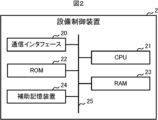
- FIG. 1 is a block diagram showing a hardware configuration of an equipment control device according to a first embodiment.
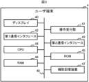
- FIG. 1 is a block diagram showing a hardware configuration of a user terminal according to a first embodiment.
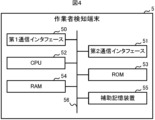
- FIG. 1 is a block diagram showing a hardware configuration of a worker detection terminal according to a first embodiment.
- FIG. 1 is a block diagram showing a functional configuration of a worker detection terminal according to a first embodiment.
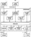
- FIG. 1 is a block diagram showing a functional configuration of an equipment control device according to a first embodiment.
- FIG. 1 is a diagram showing an equipment control device according to a first embodiment.
- FIG. 13 is a diagram showing an example of a notification screen according to the first embodiment
- 1 is a flowchart showing a procedure for a movement load estimation process according to the first embodiment.
- FIG. 13 is a diagram showing an example of a notification screen according to a modification of the first embodiment;
- FIG. 13 is a block diagram showing a functional configuration of an equipment control device according to a modification of the first embodiment.
- 10 is a flowchart showing a procedure of a movement determination process according to a modification of the first embodiment.
- FIG. 1 shows an overall configuration of an equipment control system according to a second embodiment.
- FIG. 11 is a block diagram showing a functional configuration of an equipment control device according to a second embodiment.
- FIG. 13 is a diagram showing an overall configuration of an equipment control system according to a third embodiment.
- FIG. 13 is a block diagram showing a functional configuration of an equipment control device according to a third embodiment.
- FIG. 13 is a diagram showing an example of a notification screen in the third embodiment.
- Flowchart showing the procedure of advance notification processing in the third embodiment FIG. 13 is a block diagram showing a functional configuration of an equipment control device according to a modification of the third embodiment.
- FIG. 13 is a diagram showing an overall configuration of an equipment control system according to a fourth embodiment.
- FIG. 13 is a block diagram showing a functional configuration of an equipment control device according to a fourth embodiment.
- Flowchart showing the procedure of advance notification processing in the fourth embodiment
- (Embodiment 1) 1 is a diagram showing an overall configuration of an equipment control system 1 in the first embodiment.
- the equipment control system 1 is an example of an equipment control system according to the present disclosure.
- the equipment control system 1 is a system that controls equipment devices 3 installed in each of a plurality of zones 1 to N in a building such as an office building, a research laboratory, a factory, etc., and includes an equipment control device 2, a plurality of equipment devices 3, a plurality of user terminals 4, a plurality of worker detection terminals 5, and a property information management device 6.
- Each zone is, for example, a room such as a workroom, or each area obtained by dividing one floor into a plurality of zones.
- the equipment control device 2 is an example of an equipment control device according to the present disclosure.
- the equipment control device 2 is a device that centrally controls the equipment devices 3 installed in each area, and is installed in a place where only relevant parties can enter, such as a control room in the building.
- the equipment control device 2 includes a communication interface 20, a central processing unit (CPU) 21, a read-only memory (ROM) 22, a random-access memory (RAM) 23, and an auxiliary storage device 24. These components are connected to each other via a bus 25.
- the communication interface 20 is hardware for communicating with each equipment device 3, each user terminal 4, each worker detection terminal 5, and the property information management device 6, and is, for example, an interface for wireless LAN (Local Area Network) communication.
- the CPU 21 provides overall control over the equipment control device 2. Details of the functions of the equipment control device 2 realized by the CPU 21 will be described later.
- the ROM 22 stores multiple pieces of firmware and data used when these firmware are executed.
- the RAM 23 is used as a working area for the CPU 21.
- the auxiliary storage device 24 is composed of a readable/writable non-volatile semiconductor memory, a HDD (Hard Disk Drive), etc.
- readable/writable non-volatile semiconductor memory include EPROM (Erasable Programmable Read-Only Memory), EEPROM (Electrically Erasable Programmable Read-Only Memory), and flash memory.
- the auxiliary storage device 24 stores a program for centrally controlling each piece of equipment 3 (hereinafter referred to as the "equipment control program") and data used when the equipment control program is executed.
- the equipment control device 2 is capable of acquiring the equipment control program or an update program for updating the equipment control program from another device via communication.
- these programs can be stored and distributed on computer-readable recording media such as CD-ROMs (Compact Disc Read-Only Memory), DVDs (Digital Versatile Discs), optical magnetic disks, USB (Universal Serial Bus) memory, HDDs, SSDs (Solid-State Drives), and memory cards.
- the facility equipment 3 is an example of facility equipment according to the present disclosure.
- the facility equipment 3 is, for example, an indoor unit of an air conditioner, a lighting device, a ventilation device, an air purifier, etc., and is installed in each area.
- the facility equipment 3 has a communication interface for communicating with the facility control device 2, and operates according to commands from the facility control device 2.
- the facility equipment 3 may be configured to communicate with the facility control device 2 via an external communication adapter.
- the user terminal 4 is an example of a terminal according to the present disclosure.
- the user terminal 4 is a portable electronic device used by a user, i.e., a worker working in the building, and is, for example, a smart device such as a smartphone or a tablet terminal, or a notebook PC (Personal Computer). Each worker has his/her own user terminal 4.
- the user terminal 4 includes a display 40, an operation reception unit 41, a first communication interface 42, a second communication interface 43, a CPU 44, a ROM 45, a RAM 46, and an auxiliary storage device 47. These components are connected to each other via a bus 48.
- the display 40 includes a display device such as a liquid crystal display or an organic EL (Electro Luminescence) display. Under the control of the CPU 44, the display 40 displays various screens and the like in response to user operations.
- the operation reception unit 41 includes one or more input devices such as a push button, touch panel, touch pad, keyboard, mouse, etc., receives operation input from the user, and outputs a signal related to the received operation to the CPU 44.
- the first communication interface 42 is hardware for short-range wireless communication with the worker detection terminal 5, and is, for example, an interface for BLE (Bluetooth (registered trademark) Low Energy) communication.
- the second communication interface 43 is hardware for communication with the equipment control device 2, and is, for example, an interface for wireless LAN communication.
- the CPU 44 provides overall control of the user terminal 4.
- ROM 45 stores multiple pieces of firmware and data used when these firmware are executed.
- RAM 46 is used as a working area for CPU 44.
- Auxiliary storage device 47 is composed of readable/writable non-volatile semiconductor memory, HDD, etc. Examples of readable/writable non-volatile semiconductor memory include EPROM, EEPROM, flash memory, etc.
- Auxiliary storage device 47 stores various programs including an application program for cooperating with energy saving measures in the building (hereinafter referred to as "energy saving cooperation app"), and data used when these programs are executed.
- the user terminal 4 can acquire the power-saving cooperation app or an update program for updating the power-saving cooperation app from the equipment control device 2 or another device via communication. These programs can also be stored and distributed on a computer-readable recording medium such as a CD-ROM, DVD, optical magnetic disk, USB memory, HDD, SSD, or memory card. When such a recording medium is directly or indirectly attached to the user terminal 4, the user terminal 4 can read the power-saving cooperation app or update program from the recording medium and install it on the user terminal 4.
- a computer-readable recording medium such as a CD-ROM, DVD, optical magnetic disk, USB memory, HDD, SSD, or memory card.
- the power-saving cooperation app causes the user terminal 4 to periodically transmit a wireless signal including a user terminal ID (identifier), which is identification information for the user terminal 4, via the first communication interface 42.
- the power-saving cooperation app also allows the worker to check information related to movement of the work location sent from the equipment control device 2, for example by push notification. Details of the information sent from the equipment control device 2 will be described later.
- the worker detection terminal 5 is installed in each area, and detects the worker by wirelessly communicating with the user terminal 4 used by the worker. As shown in Fig. 4, the worker detection terminal 5 includes a first communication interface 50, a second communication interface 51, a CPU 52, a ROM 53, a RAM 54, and an auxiliary storage device 55. These components are connected to each other via a bus 56.
- the first communication interface 50 is hardware for short-range wireless communication with the user terminal 4, for example, an interface for performing BLE communication.
- the second communication interface 51 is hardware for communicating with the equipment control device 2, for example, an interface for performing wireless LAN communication.
- the CPU 52 provides overall control of the worker detection terminal 5. The functions of the worker detection terminal 5 realized by the CPU 52 will be described in detail later.
- ROM 53 stores multiple pieces of firmware and data used when these pieces of firmware are executed.
- RAM 54 is used as a working area for CPU 52.
- Auxiliary storage device 55 is composed of a readable/writable non-volatile semiconductor memory, HDD, etc. Examples of readable/writable non-volatile semiconductor memory include EPROM, EEPROM, flash memory, etc.
- the auxiliary storage device 55 stores a worker detection program and data used when the worker detection program is executed.
- the worker detection program is a program that describes the process of receiving a wireless signal transmitted from a user terminal 4, extracting and acquiring the user terminal ID of the user terminal 4 from the received wireless signal, measuring and acquiring the radio wave strength (also called electric field strength) when the wireless signal is received, and transmitting a notification (hereinafter referred to as "worker detection notification") including the acquired user terminal ID and radio wave strength to the equipment control device 2.
- the worker detection terminal 5 can acquire the worker detection program or an update program for updating the worker detection program from the equipment control device 2 or another device via communication. These programs can also be stored and distributed on computer-readable recording media such as CD-ROMs, DVDs, optical magnetic disks, USB memory, HDDs, SSDs, and memory cards. When such a recording media is directly or indirectly attached to the worker detection terminal 5, the worker detection terminal 5 can read the worker detection program or update program from the recording media and install it in itself.
- computer-readable recording media such as CD-ROMs, DVDs, optical magnetic disks, USB memory, HDDs, SSDs, and memory cards.
- the property information management device 6 is a computer that manages the latest property information of the building.
- the property information includes the layout of each floor, the installation positions of each equipment 3 and each worker detection terminal 5, etc.
- the property information management device 6 includes a communication interface, and in response to a request from the equipment control device 2, transmits the latest property information of the building to the equipment control device 2.
- Fig. 5 is a block diagram showing the functional configuration of the worker detection terminal 5.
- the worker detection terminal 5 includes a wireless signal receiving unit 500 and a worker detection notifying unit 501. These functional units are realized by the CPU 52 of the worker detection terminal 5 executing the above-mentioned worker detection program stored in the auxiliary storage device 55.
- the wireless signal receiving unit 500 receives a wireless signal periodically transmitted from the user terminal 4 via the first communication interface 50, and extracts and acquires the user terminal ID of the user terminal 4 from the received wireless signal.
- the wireless signal receiving unit 500 also measures and acquires the radio wave strength when the wireless signal is received from the user terminal 4.
- the wireless signal receiving unit 500 measures and acquires the RSSI (Received Signal Strength Indicator) of the wireless signal received from the user terminal 4.
- the worker detection notification unit 501 generates a worker detection notification that includes an ID that identifies itself (i.e., the worker detection terminal 5) and the acquired user terminal ID and radio wave intensity, and transmits the generated worker detection notification to the equipment control device 2 via the second communication interface 51.
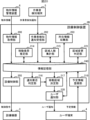
- Fig. 6 is a block diagram showing the functional configuration of the equipment control device 2.
- the equipment control device 2 includes a property information acquisition unit 200, a movement load estimation unit 201, a worker detection notification receiving unit 202, a location information collection unit 203, a zone number of people counting unit 204, an equipment control unit 205, a notification necessity determination unit 206, a movement zone determination unit 207, and a user notification unit 208.
- These functional units are realized by the CPU 21 of the equipment control device 2 executing the above-mentioned equipment control program stored in the auxiliary storage device 24.
- the property information acquisition unit 200 acquires property information from the property information management device 6 through communication.
- the timing at which the property information acquisition unit 200 acquires the property information is an arbitrary design matter.
- the property information acquisition unit 200 may acquire the property information from the property information management device 6 periodically, or may acquire the property information from the property information management device 6 in response to an operator's operation.
- the property information acquisition unit 200 stores the acquired property information in the information storage unit 240.
- the information storage unit 240 is an example of an information storage means related to the present disclosure, and is a memory area provided by the auxiliary storage device 24.
- the travel load estimation unit 201 is an example of a travel load estimation means according to the present disclosure.
- the travel load estimation unit 201 estimates the travel load between each area based on the property information stored in the information storage unit 240.
- the travel load estimation unit 201 acquires the distance between each area and route information between the areas from the property information, and estimates the travel load, which is a feature including the travel time and the amount of exercise between the areas, based on the acquired distance and route information.
- the route information includes information such as whether the travel is within the same floor, whether the travel uses stairs, and whether the travel uses an elevator. Note that if both stairs and an elevator are available, the use of the elevator is prioritized.
- the travel load estimation unit 201 saves travel load information indicating the estimated travel load between each area in the information storage unit 240.
- the worker detection notification receiving unit 202 receives the worker detection notifications sent from the worker detection terminal 5.
- the worker detection notification receiving unit 202 sorts the received worker detection notifications in chronological order for each ID of the worker detection terminal 5 that sent the notifications, and stores them in the information storage unit 240.
- the location information collection unit 203 collects location information indicating the current location of each worker at regular intervals (e.g., every minute). In detail, the location information collection unit 203 identifies the area in which the worker corresponding to the user terminal ID is located based on the worker detection notification from each worker detection terminal 5, which is stored in the information storage unit 240, i.e., the user terminal ID and radio wave intensity included in the worker detection notification corresponding to each area. The location information collection unit 203 stores location information in the information storage unit 240 that associates each worker (in detail, the user ID of each worker) with the identified area (in detail, the area ID of each area).
- the area number of people counting unit 204 is an example of a counting means according to the present disclosure.
- the area number of people counting unit 204 counts the number of workers in each area every fixed time (e.g., 1 minute). In detail, the area number of people counting unit 204 counts the number of workers in each area based on the location information corresponding to each worker that is stored in the information storage unit 240.
- the area number of people counting unit 204 stores area number of people information in the information storage unit 240 that associates the area ID with the counted number of current workers in the area.
- the equipment control unit 205 is an example of an equipment control means according to the present disclosure.
- the equipment control unit 205 controls the operation of each equipment device 3.
- the equipment control unit 205 controls the operation of each equipment device 3 based on the operation plan of the equipment device 3 and the number of workers in each area.
- Operation plan information indicating the operation plan of each equipment device 3 (including, for example, the time period during which the equipment device 3 is operated, the set temperature, etc.) is stored in the information storage unit 240.
- the equipment control unit 205 controls the operation of each equipment device 3 according to the operation plan, and when the number of workers in the corresponding area satisfies a predetermined power saving condition, it instructs the equipment device 3 installed in the area to operate at a lower capacity than the current capacity.
- the power saving condition is satisfied, for example, when the number of workers in the area is zero, that is, when there are no workers in the area.
- the equipment control unit 205 stops the operation of the equipment 3. Also, if the number of workers in the area is zero and the equipment 3 installed in the area is a lighting device, the equipment control unit 205 turns off the equipment 3.
- the notification necessity determination unit 206 is an example of a notification necessity determination means according to the present disclosure.
- the notification necessity determination unit 206 determines whether or not notification is required for the workers in each area based on the current number of workers in that area. In detail, if the number of workers in that area satisfies a predetermined notification condition, the notification necessity determination unit 206 determines that notification is required for the workers in that area, and if the number of workers in that area does not satisfy the notification condition, it determines that notification is not required for the workers.
- the notification condition is satisfied, for example, when the number of workers in that area is between 1 and 3.
- the notification condition may be common to each area, or may be defined for each area.
- the travel area determination unit 207 is an example of a travel area determination means according to the present disclosure.
- the travel area determination unit 207 determines an area to be recommended as a travel destination for the worker, i.e., an area suitable as a travel destination for the worker, based on the travel load between areas (more specifically, the travel load from the area to each of the other areas). In this case, the travel area determination unit 207 determines, as the recommended travel destination, the area with the smallest travel load from the area where the worker is located, among all areas where other workers are located and that do not satisfy the notification conditions.
- the user notification unit 208 is an example of a notification means according to the present disclosure.
- the movement area determination unit 207 determines an area recommended as a movement destination
- the user notification unit 208 notifies the user terminal 4 of the worker to encourage the worker to move to the determined area.
- the user notification unit 208 transmits a user notification to the user terminal 4 of the worker to encourage the worker to move to the area determined as the movement destination.
- the user terminal 4 that receives the user notification displays a user notification screen such as that shown in FIG. 7 on the display 40, for example, by push notification.
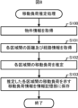
- ⁇ Movement Load Estimation Processing> 8 is a flowchart showing the procedure of a movement load estimation process executed by the equipment control device 2.
- the equipment control device 2 executes the following movement load estimation process periodically or in response to an operation by an operator.
- Step S100 The equipment control device 2 acquires the latest property information of the building through communication with the property information management device 6.
- the equipment control device 2 stores the acquired property information in the information storage unit 240. After that, the processing of the equipment control device 2 transitions to step S101.
- Step S101 The equipment control device 2 acquires the distance between each area and the route information between the areas from the property information. After that, the process of the equipment control device 2 transitions to step S102.
- Step S102 The equipment control device 2 estimates a travel load including a travel time and an amount of exercise between each zone based on the distance between each zone and the route information. After that, the process of the equipment control device 2 transitions to step S103.
- Step S103 The equipment control device 2 stores travel load information indicating the estimated travel load between each area in the information storage unit 240. Thereafter, the equipment control device 2 ends the travel load estimation process.
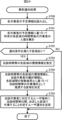
- ⁇ Facility control and notification processing> 9 is a flowchart showing the procedure of equipment control and notification processing executed by the equipment control device 2.
- the equipment control device 2 executes the following equipment control and notification processing every fixed time (for example, every minute).
- Step S200 The equipment control device 2 collects location information indicating the current location of each worker.
- the location information includes the user ID of the worker and the area ID of the area in which the worker is located. After that, the process of the equipment control device 2 transitions to step S201.
- Step S201 The equipment control device 2 counts the number of workers currently present in each area based on the collected location information. After that, the processing of the equipment control device 2 transitions to step S202.
- Step S202 The equipment control device 2 determines whether or not there is an area that satisfies the power saving condition. If there is an area that satisfies the power saving condition (step S202; YES), the processing of the equipment control device 2 transitions to step S203. If there is no area that satisfies the power saving condition (step S202; NO), the processing of the equipment control device 2 transitions to step S204.
- Step S203 The equipment control device 2 instructs the equipment 3 installed in the area that satisfies the power saving condition to operate at low capacity.
- the equipment control device 2 transmits a control command instructing the equipment 3 to operate at low capacity. After that, the processing of the equipment control device 2 transitions to step S204.
- Step S204 The equipment control device 2 judges whether or not there is an area that satisfies the notification condition. If there is an area that satisfies the notification condition (step S204; YES), the processing of the equipment control device 2 transitions to step S205. If there is no area that satisfies the notification condition (step S204; NO), the equipment control device 2 ends the equipment control and notification processing in this cycle.
- Step S205 The equipment control device 2 determines a recommended area as a destination for the worker based on the travel load between the areas. After that, the process of the equipment control device 2 transitions to step S206.
- Step S206 The equipment control device 2 transmits a user notification to the user terminal 4 corresponding to the worker, urging the worker to move to the determined area. After that, the equipment control device 2 ends the equipment device and notification processing for this cycle.
- the equipment control device 2 counts the number of workers in each area of the building, and controls the operation of the equipment 3 corresponding to that area based on the number of workers in that area.
- the equipment control device 2 instructs the equipment 3 corresponding to an area that satisfies the power saving conditions (for example, an area where no workers are present) to operate at low capacity, such as by stopping operation. This makes it possible to reduce the power consumption of the equipment 3.
- the equipment control device 2 determines an area to recommend as a destination for the worker based on the travel load between each area estimated in advance, and notifies the user terminal 4 of the worker to encourage travel to the determined area. This makes it possible to reduce areas with a small number of workers, and as a result, it becomes possible to further reduce the power consumption of the equipment 3.
- the recommended destination is determined based on the travel load from the current area, reducing the hassle of workers having to travel.
- the latest property information may be stored in the information storage unit 240 by the operator.
- the equipment control device 2 may be configured to notify the user of the user terminal 4 by email or a social networking service (SNS).
- SNS social networking service
- the user notification unit 208 of the equipment control device 2 may present a plurality of areas recommended as destinations to the worker.
- the user notification unit 208 of the equipment control device 2 may present a plurality of areas (e.g., three) to the user in order of the smallest travel load.
- the configuration may be such that the workers in each area are identified by a camera, a retina authentication device, a fingerprint authentication device, an IC card reader, or the like installed in each area, and the number of people in each area is tallied.
- the user notification unit 208 of the equipment control device 2 may also notify the user terminal 4 of information regarding the movement load from the area where the worker is located to each of the other areas. For example, when the user taps on a user notification screen as shown in Fig. 7 on the user terminal 4, the equipment control device 2 transmits information indicating a list of movement loads to other areas to the user terminal 4. The user terminal 4 that has received the information uses a power saving cooperation app to display on the display 40 a notification screen indicating a list of movement loads to other areas as shown in Fig. 10.
- Fig. 11 is a block diagram showing the functional configuration of the equipment control device 2 in this modified example. As shown in Fig. 11, the functional configuration of the equipment control device 2 in this modified example differs from the functional configuration of the equipment control device 2 shown in Fig. 6 in that it includes a user notification unit 209 instead of the user notification unit 208, and newly includes a movement determination unit 210.
- the user notification unit 209 like the user notification unit 208, sends a user notification to the user terminal 4 of the worker, encouraging the worker to move to the area determined as the destination by the movement area determination unit 207. Furthermore, the user notification unit 209 generates user-notified information including the user ID of the worker, the user terminal ID of the user terminal 4 of the worker, the time of notification, and the area ID of the area to which the worker is encouraged to move, and stores the generated user-notified information in the information storage unit 240.
- the movement determination unit 210 is an example of a movement determination means according to the present disclosure.
- the movement determination unit 210 determines whether the worker has moved to the area to which the worker was prompted to move after receiving the user notification, based on the user notified information stored in the information storage unit 240 and the history of the worker's location information corresponding to the user notified information. If the worker has moved to the area, the movement determination unit 210 generates worker performance information indicating that the worker has responded to the user notification, and stores the information storage unit 240.
- the worker performance information is used as a basis for determining whether to give an incentive to workers for cooperating in saving electricity.
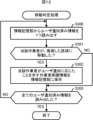
- FIG. 12 is a flowchart showing the steps of the movement determination process executed by the equipment control device 2 of this modified example.
- the equipment control device 2 executes the following movement determination process when the end of work hours arrives.
- Step S300 The equipment control device 2 reads one piece of user notified information from the information storage unit 240. After that, the processing of the equipment control device 2 transitions to step S301.
- Step S301 The equipment control device 2 judges whether or not the worker corresponding to the user notified information has moved to the recommended area. If the worker has moved to the area (step S301; YES), the processing of the equipment control device 2 proceeds to step S302. If the worker has not moved to the area (step S301; NO), the processing of the equipment control device 2 proceeds to step S303.
- Step S302 The equipment control device 2 stores the worker performance information indicating that the worker has responded to the user notification in the information storage unit 240. After that, the process of the equipment control device 2 transitions to step S303.
- Step S303 The equipment control device 2 judges whether or not all the user notified information has been read from the information storage unit 240. If all the user notified information has not been read (step S303; NO), the processing of the equipment control device 2 returns to step S300. If all the user notified information has been read (step S303; YES), the equipment control device 2 ends the movement judgment processing.
- All or part of the functional units (see FIG. 5 ) of the worker detection terminal 5 may be realized by dedicated hardware. Also, all or part of the functional units (see FIG. 6 ) of the equipment control device 2 may be realized by dedicated hardware.
- the dedicated hardware is, for example, a single circuit, a composite circuit, a programmed processor, an ASIC (Application-Specific Integrated Circuit), an FPGA (Field-Programmable Gate Array), or a combination of these.
- FIG. 13 is a diagram showing the overall configuration of an equipment control system 1A in embodiment 2.
- the equipment control system 1A is an example of an equipment control system according to the present disclosure.
- the equipment control system 1A is a system that controls equipment devices 3 installed in each of multiple zones 1 to N in a building such as an office building, a research laboratory, a factory, etc., and includes an equipment control device 2A, multiple equipment devices 3, multiple user terminals 4, multiple worker detection terminals 5, and a property information management device 6.
- Each zone is, for example, a room such as a workroom, or each area obtained by dividing a floor into multiple zones, etc.
- the equipment control device 2A is an example of an equipment control device according to the present disclosure.
- the equipment control device 2A is a device that centrally controls the equipment devices 3 installed in each area, and is installed in a location where only relevant parties can enter, such as a control room in the building.
- the hardware configuration of the equipment control device 2A is the same as the hardware configuration of the equipment control device 2 (see FIG. 2).
- the equipment control device 2A includes a property information acquisition unit 200, a movement load estimation unit 201, a worker detection notification receiving unit 202, a location information collection unit 203, an area number of people counting unit 204, an equipment control unit 205, a notification necessity determination unit 206, a user notification unit 208, an environmental information collection unit 211, a movement area determination unit 212, and a preference information registration unit 213.
- These functional units are realized by the CPU 21 of the equipment control device 2A executing an equipment control program stored in the auxiliary storage device 24.
- the functional configuration of the equipment control device 2A differs from the functional configuration of the equipment control device 2 in embodiment 1 (see FIG. 6) in that it includes a movement area determination unit 212 instead of the movement area determination unit 207, and newly includes an environmental information collection unit 211 and a preference information registration unit 213.
- the environmental information collection unit 211 is an example of an environmental information collection means according to the present disclosure, and collects environmental information for each area.
- the environmental information is, for example, air temperature.
- the environmental information collection unit 211 collects environmental information from each equipment device 3 at regular intervals (for example, every minute).
- the environmental information collection unit 211 transmits a command to each equipment device 3 at regular time intervals, requesting the transmission of environmental information. Upon receiving such a command, the equipment device 3 transmits environmental information including its own equipment ID and the value of the air temperature measured by its own temperature sensor to the equipment control device 2A. The environmental information collection unit 211 receives the environmental information sent from each equipment device 3, and stores the received environmental information in chronological order for each zone corresponding to the equipment device 3 in the information storage unit 240.
- the preference information registration unit 213 stores the worker's preference information in the information storage unit 240 in association with the worker's user ID.
- the preference information is information that indicates the worker's preferences for the environment.
- the preference information includes, for example, the range of air temperatures desired by the worker.
- the user can register the preference information in advance in the equipment control device 2A using the power saving cooperation app.
- the travel area determination unit 212 is an example of a travel area determination means according to the present disclosure.
- the travel area determination unit 212 determines an area to recommend as a travel destination for the worker based on the environmental information of each area, the preference information of the worker, and the travel load between each area. In this case, the travel area determination unit 212 first selects one or more areas where other workers are present and where the current air temperature is within the range of the air temperature desired by the worker from among all areas that do not satisfy the notification condition. Then, the travel area determination unit 212 determines, from all selected areas, the area with the smallest travel load from the area where the worker is present as the recommended travel destination.
- the travel area determination unit 212 selects multiple areas with air temperatures that are closest to that range, and determines, from among all the selected areas, the area that has the smallest travel load from the area where the worker is located as the recommended travel destination.
- the user notification unit 208 transmits a user notification to the user terminal 4 of the worker encouraging the worker to move to the area.
- ⁇ Facility control and notification processing> 15 is a flowchart showing the procedure of equipment control and notification processing executed by the equipment control device 2 A.
- the equipment control device 2 A executes the following equipment control and notification processing every fixed time (for example, every minute).
- Step S400 The equipment control device 2A collects environmental information for each zone from each equipment device 3. After that, the processing of the equipment control device 2A transitions to step S401.
- Step S401 The equipment control device 2A collects location information indicating the current location of each worker. After that, the process of the equipment control device 2A transitions to step S402.
- Step S402 The equipment control device 2A counts the number of workers currently present in each area based on the collected location information. After that, the processing of the equipment control device 2A transitions to step S403.
- Step S403 The equipment control device 2A judges whether or not there is an area that satisfies the power saving condition. If there is an area that satisfies the power saving condition (step S403; YES), the processing of the equipment control device 2A transitions to step S404. If there is no area that satisfies the power saving condition (step S403; NO), the processing of the equipment control device 2A transitions to step S405.
- Step S404 The equipment control device 2A commands the equipment 3 installed in the area that satisfies the power saving condition to operate at low capacity.
- the equipment control device 2A transmits a control command to the equipment 3 to operate at low capacity. After that, the processing of the equipment control device 2A transitions to step S405.
- Step S405 The equipment control device 2A judges whether or not there is an area that satisfies the notification condition. If there is an area that satisfies the notification condition (step S405; YES), the processing of the equipment control device 2A transitions to step S406. If there is no area that satisfies the notification condition (step S405; NO), the equipment control device 2A ends the equipment control and notification processing for this cycle.
- Step S406 The equipment control device 2A determines a recommended area as a destination for the worker based on the environmental information of each area, the preference information of the worker, and the travel load between the areas. After that, the processing of the equipment control device 2A transitions to step S407.
- Step S407 The equipment control device 2A transmits a user notification to the user terminal 4 corresponding to the worker, urging the worker to move to the determined area. After that, the equipment control device 2A ends the equipment device and notification processing for this cycle.
- the equipment control device 2A counts the number of workers in each area of the building, and controls the operation of the equipment 3 corresponding to that area based on the number of workers in that area.
- the equipment control device 2A instructs the equipment 3 corresponding to an area that satisfies the power saving conditions (for example, an area where no workers are present) to operate at low capacity, such as by stopping operation. This makes it possible to reduce the power consumption of the equipment 3.
- the equipment control device 2A determines an area to recommend as a destination for the worker based on the environmental information of each area, the preference information of the worker, and the travel load between each area estimated in advance, and notifies the user terminal 4 of the worker to encourage the worker to travel to the determined area. This makes it possible to reduce areas with a small number of workers, and as a result, it becomes possible to further reduce the power consumption of the equipment 3.
- the recommended destination is determined based on the environmental information for each area, the preference information for the worker, and the travel load from the current area, which reduces the inconvenience for the worker when traveling and makes it possible to present an area that is more suitable for the worker.
- the environmental information may include, in addition to air temperature, humidity, illuminance, etc. Furthermore, the preference information may include a humidity range, an illuminance range, etc., desired by the worker.
- the environmental information may be acquired from a dedicated sensor that is installed in each area and is separate from the facility equipment 3.
- the user notification unit 208 of the equipment control device 2A When the user notification unit 208 of the equipment control device 2A notifies the user terminal 4 of the relevant worker to encourage him or her to move to the area determined by the movement area determination unit 212, it may also notify the user terminal 4 of the relevant worker of environmental information for the area or environmental information for each area including the environmental information for the area.
- All or part of the functional units of the equipment control device 2A may be realized by dedicated hardware, such as a single circuit, a composite circuit, a programmed processor, an ASIC, an FPGA, or a combination thereof.
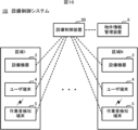
- FIG. 16 is a diagram showing the overall configuration of an equipment control system 1B in embodiment 3.
- the equipment control system 1B is an example of an equipment control system according to the present disclosure.
- the equipment control system 1B is a system that controls equipment devices 3 installed in each of multiple zones 1 to N in a building such as an office building, a research laboratory, a factory, etc., and includes an equipment control device 2B, multiple equipment devices 3, multiple user terminals 4, multiple worker detection terminals 5, and a property information management device 6.
- Each zone is, for example, a room such as a workroom, or each area obtained by dividing a floor into multiple zones.
- the equipment control device 2B is an example of an equipment control device according to the present disclosure.
- the equipment control device 2B is a device that centrally controls the equipment devices 3 installed in each area, and is installed in a location where only relevant parties can enter, such as a control room in the building.
- the hardware configuration of the equipment control device 2B is the same as the hardware configuration of the equipment control device 2 (see FIG. 2).
- the equipment control device 2B includes a property information acquisition unit 200, a worker detection notification receiving unit 202, a location information collection unit 203, an equipment control unit 205, a movement load estimation unit 214, an area number of people counting unit 215, a notification necessity determination unit 216, a movement area determination unit 217, a user notification unit 218, and a schedule information registration unit 219. These functional units are realized by the CPU 21 of the equipment control device 2B executing an equipment control program stored in the auxiliary storage device 24.
- the functional configuration of the equipment control device 2B differs from the functional configuration of the equipment control device 2 in embodiment 1 (see FIG. 6) in that, instead of the movement load estimation unit 201, the area number of people counting unit 204, the notification necessity determination unit 206, the movement area determination unit 207, and the user notification unit 208, the equipment control device 2B includes a movement load estimation unit 214, an area number of people counting unit 215, a notification necessity determination unit 216, a movement area determination unit 217, and a user notification unit 218, and also includes a schedule information registration unit 219.
- the schedule information registration unit 219 stores the schedule information of the worker in the information storage unit 240 in association with the user ID of the worker.
- the schedule information includes, for example, the planned work location (i.e., the area) of the worker and the time period during which work is planned to be performed at the work location.
- the user can use the power saving cooperation app to register the schedule information in advance in the equipment control device 2B.
- the travel load estimation unit 214 estimates the travel load between each area, similar to the travel load estimation unit 201 in the first embodiment. Furthermore, the travel load estimation unit 214 estimates the travel load from the entrance of the building to each area. The travel load estimation unit 214 stores information indicating the estimated travel load between each area and the travel load from the entrance of the building to each area in the information storage unit 240.
- the area number of people counting unit 215 is an example of a counting means according to the present disclosure. Like the area number of people counting unit 204 in the first embodiment, the area number of people counting unit 215 counts the number of workers in each area every fixed time (e.g., one minute). Furthermore, when a predetermined timing arrives, the area number of people counting unit 215 counts the number of workers in each area for each future time slot based on the schedule information of each worker. For example, at 8:00 a.m. on a workday, the area number of people counting unit 215 counts the number of workers in each area for each hour until 8:00 p.m. on that day. The area number of people counting unit 215 stores information indicating the counted number of workers in each area for each future time slot in the information storage unit 240.
- the area number of people counting unit 215 stores information indicating the counted number of workers in each area for each future time slot in the information storage unit 240.
- the notification necessity determination unit 216 is an example of a notification necessity determination means according to the present disclosure.
- the notification necessity determination unit 216 determines whether or not notification is necessary for workers in each area based on the current number of workers in that area. Furthermore, the notification necessity determination unit 216 determines whether or not advance notification is necessary for workers who are scheduled to be in that area during a future time period (e.g., 8:00 to 9:00, 9:00 to 10:00, 10:00 to 11:00, ...) based on the number of workers in each area. In detail, when the number of workers in any time period in any area satisfies a predetermined notification condition, the notification necessity determination unit 216 determines that advance notification is necessary for workers who are scheduled to be in that area during that time period. The notification condition is satisfied, for example, when the number of workers in the area is 1 to 3. The notification condition may be common to each area and each time period, or may be defined for each area or time period.
- the travel area determination unit 217 determines an area to be recommended as a travel destination for the worker, similar to the travel area determination unit 207 in the first embodiment. Furthermore, when the notification necessity determination unit 216 determines that advance notification to the worker is necessary, the travel area determination unit 217 determines an area that is a recommended work location for the worker in the relevant time period based on the travel load between each area. In detail, the travel area determination unit 217 determines, as the recommended work location, the area with the smallest travel load from the area where the user is scheduled to be located before, among all areas in which other workers are present in the relevant time period and which do not satisfy the notification conditions.
- the movement area determination unit 217 determines, as the recommended work location, the area in which other workers are present during that time period and among all areas that do not satisfy the notification conditions, the area with the smallest movement load from the entrance of the building.
- the user notification unit 218 is an example of a notification means according to the present disclosure. Similar to the user notification unit 208 in the first embodiment, when the movement area determination unit 217 determines an area recommended as the movement destination for the worker, the user notification unit 218 notifies the user terminal 4 of the worker to encourage the worker to move to the determined area. Furthermore, when the movement area determination unit 217 determines an area recommended as the work location for the worker, the user notification unit 218 notifies the user terminal 4 of the worker to encourage the worker to change the work location for that time period to the determined area.
- the user notification unit 218 transmits a user notification to the user terminal 4 of the worker, encouraging the worker to work in the determined area instead of the area originally planned for the work during the time period.
- the user terminal 4 that receives the user notification displays a user notification screen such as that shown in FIG. 18 on the display 40, for example, by push notification.
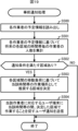
- ⁇ Advance notification process> 19 is a flowchart showing the procedure of the advance notification process executed by the equipment control device 2 B.
- a predetermined timing for example, at 8:00 a.m. on a work day
- the equipment control device 2 B executes the following advance notification process.
- Step S500 The equipment control device 2B reads out the schedule information of each worker from the information storage unit 240. After that, the processing of the equipment control device 2B transitions to step S501.
- Step S501 The equipment control device 2B tallies the number of workers in each area for each time period in the future based on the schedule information of each worker. After that, the processing of the equipment control device 2B transitions to step S502.
- Step S502 The equipment control device 2B judges whether or not there is an area that satisfies the notification condition in any of the time periods. If there is an area that satisfies the notification condition (step S502; YES), the processing of the equipment control device 2B transitions to step S503. If there is no area that satisfies the notification condition in any of the time periods (step S502; NO), the equipment control device 2B ends the advance notification processing.
- Step S503 The equipment control device 2B determines an area to be recommended as a work location for the worker in the relevant time period based on the travel load between the areas. After that, the processing of the equipment control device 2B transitions to step S504.
- Step S504 The equipment control device 2B transmits a user notification to the user terminal 4 corresponding to the worker, urging the worker to work in the determined area during the time period. After that, the equipment control device 2B ends the advance notification process.
- the equipment control system 1B in this embodiment achieves the same effects as the equipment control system 1 in the first embodiment. Furthermore, in the equipment control system 1B, the equipment control device 2B determines whether there is an area that satisfies the notification conditions in a future time period based on the schedule information of each worker. If a corresponding area is found, the equipment control device 2B transmits a user notification to the user terminal 4 of the worker who is scheduled to work in that area during that time period, encouraging the worker to work in another recommended area. This makes it possible to reduce the amount of work by workers in areas that satisfy the notification conditions, and further reduce the power consumption of the equipment 3.
- the user notification unit 218 of the equipment control device 2B may present multiple areas recommended as work locations for the relevant time period when providing advance notification to the user terminal 4 of the relevant worker.
- the user notification unit 218 of the equipment control device 2B may present to the user multiple (e.g., three) areas in order of least travel load.
- the equipment control device 2B may determine whether the worker who has been notified in advance has changed the work location to the recommended area, and if the worker has changed the work location to the recommended area, store information indicating that in the information storage unit 240.
- Fig. 20 is a block diagram showing the functional configuration of the equipment control device 2B in this modified example. As shown in Fig. 20, the functional configuration of the equipment control device 2B in this modified example differs from the functional configuration of the equipment control device 2B shown in Fig. 17 in that it includes a user notification unit 220 instead of the user notification unit 218 and newly includes an area change determination unit 221.
- the user notification unit 220 transmits a user notification to the user terminal 4 of the worker encouraging the worker to work in that area during the relevant time period. At that time, the user notification unit 220 generates user pre-notified information including the user ID of the worker, the user terminal ID of the user terminal 4 of the worker, the time of notification, the relevant time period, and the area ID of the recommended area, and stores the generated user pre-notified information in the information storage unit 240.
- the area change determination unit 221 determines whether the worker has changed the work location for the relevant time period to the recommended area based on the user advance notified information stored in the information storage unit 240 and the history of the worker's location information corresponding to the user advance notified information. If the worker has changed the work location for the relevant time period to the recommended area, the area change determination unit 221 generates worker performance information indicating that the worker has responded to the advance user notification and stores it in the information storage unit 240. For example, the worker performance information is used as a basis for determining whether to give an incentive to workers for cooperating in saving electricity.
- FIG. 21 is a flowchart showing the procedure for the change determination process executed by the equipment control device 2B of this modified example.
- the equipment control device 2B executes the following change determination process when the workday ends.
- Step S600 The equipment control device 2B reads out one piece of user advance notified information from the information storage unit 240. After that, the processing of the equipment control device 2B transitions to step S601.
- Step S601 The equipment control device 2B judges whether or not the worker corresponding to the user advance notification information has changed the work place to the recommended area. If the worker has changed the work place to the area (step S601; YES), the processing of the equipment control device 2B transitions to step S602. If the worker has not changed the work place to the area (step S601; NO), the processing of the equipment control device 2B transitions to step S603.
- Step S602 The equipment control device 2B stores worker performance information indicating that the worker has responded to the user notification in the information storage unit 240. After that, the processing of the equipment control device 2B transitions to step S603.
- Step S603 The equipment control device 2B judges whether or not all the user advance notified information has been read from the information storage unit 240. If all the user advance notified information has not been read (step S603; NO), the processing of the equipment control device 2B returns to step S600. If all the user advance notified information has been read (step S603; YES), the equipment control device 2B ends the change judgment processing.
- All or part of the functional units of the equipment control device 2B may be realized by dedicated hardware, such as a single circuit, a composite circuit, a programmed processor, an ASIC, an FPGA, or a combination thereof.
- FIG. 22 is a diagram showing the overall configuration of an equipment control system 1C in embodiment 4.
- the equipment control system 1C is an example of an equipment control system according to the present disclosure.
- the equipment control system 1C is a system that controls equipment devices 3 installed in each of multiple zones 1 to N in a building such as an office building, a research laboratory, a factory, etc., and includes an equipment control device 2C, multiple equipment devices 3, multiple user terminals 4, multiple worker detection terminals 5, and a property information management device 6.
- Each zone is, for example, a room such as a workroom, or each area obtained by dividing a floor into multiple zones, etc.
- the equipment control device 2C is an example of an equipment control device according to the present disclosure.
- the equipment control device 2C is a device that centrally controls the equipment devices 3 installed in each area, and is installed in a location where only relevant parties can enter, such as a control room in the building.
- the hardware configuration of the equipment control device 2C is the same as the hardware configuration of the equipment control device 2 (see FIG. 2).
- the equipment control device 2C includes a property information acquisition unit 200, a worker detection notification receiving unit 202, a location information collection unit 203, an equipment control unit 205, a movement load estimation unit 214, an area number of people counting unit 215, a notification necessity determination unit 216, a user notification unit 218, a schedule information registration unit 219, an environmental information collection unit 222, a movement area determination unit 223, a preference information registration unit 224, and an environmental information estimation unit 225.
- These functional units are realized by the CPU 21 of the equipment control device 2C executing an equipment control program stored in the auxiliary storage device 24.
- the functional configuration of the equipment control device 2C differs from the functional configuration of the equipment control device 2B in embodiment 3 (see FIG. 17) in that it includes a movement area determination unit 223 instead of the movement area determination unit 217, and newly includes an environmental information collection unit 222, a preference information registration unit 224, and an environmental information estimation unit 225.
- the environmental information collection unit 222 collects environmental information for each area.
- the environmental information is, for example, air temperature.
- the environmental information collection unit 222 collects environmental information from each equipment device 3 at regular intervals (for example, every minute).
- the environmental information collection unit 222 transmits a command to each equipment device 3 at regular intervals, requesting the transmission of environmental information. Upon receiving such a command, the equipment device 3 transmits environmental information including its own equipment ID and the value of the air temperature measured by its own temperature sensor to the equipment control device 2C. The environmental information collection unit 222 receives the environmental information sent from each equipment device 3, and stores the received environmental information in chronological order for each area corresponding to the equipment device 3 in the information storage unit 240.
- the preference information registration unit 224 stores the preference information of the worker in the information storage unit 240 in association with the user ID of the worker.
- the preference information is information that indicates the worker's preferences for the environment.
- the preference information includes, for example, the range of air temperatures desired by the worker.
- the user can register the preference information in advance in the equipment control device 2C using the power saving cooperation app.
- the environmental information estimation unit 225 estimates environmental information for each area during that time period.
- the environmental information estimation unit 225 estimates environmental information such as air temperature for each area during that time period based on the current environmental information for each area and the operation plan for each equipment 3 (including, for example, the operating time period and set temperature).
- the environmental information estimation unit 225 may also estimate environmental information for each area during that time period by taking into account the outside air temperature for that time period in the weather forecast, the number of workers in each area during that time period, etc.
- the movement area determination unit 223 determines an area recommended as a movement destination for the worker, similar to the movement area determination unit 217 of the third embodiment. Furthermore, when the notification necessity determination unit 216 determines that advance notification to the worker is necessary, the movement area determination unit 223 determines an area that is a recommended work location for the worker in the relevant time period, based on the environmental information of each area in the relevant time period, the preference information of the worker, and the travel load between each area.
- the movement area determination unit 223 first selects one or more areas where other workers are present during the time period and where the air temperature during the time period falls within the range of the worker's desired air temperature from among all areas that do not satisfy the notification conditions. The movement area determination unit 223 then determines, from among all selected areas, the area with the smallest travel load from the area where the worker is previously scheduled to be located as the movement destination. If there is no area with an air temperature within the range of the worker's desired air temperature, the movement area determination unit 223 selects multiple areas with air temperatures closer to that range, and determines, from among all selected areas, the area with the smallest travel load from the area where the worker is previously scheduled to be located as the movement destination.
- the movement area determination unit 223 determines that the area with the smallest movement load from the entrance of the building is the recommended work location among all the selected areas.
- ⁇ Advance notification process> 24 is a flowchart showing the procedure of the advance notification process executed by the equipment control device 2C.
- a predetermined timing for example, at 8:00 a.m. on a work day
- the equipment control device 2C executes the following advance notification process.
- Step S700 The equipment control device 2C reads out the schedule information of each worker from the information storage unit 240. After that, the processing of the equipment control device 2C transitions to step S701.
- Step S701 The equipment control device 2C tallies up the number of workers in each area for each time period in the future based on the schedule information of each worker. After that, the processing of the equipment control device 2C transitions to step S702.
- Step S702 The equipment control device 2C judges whether or not there is an area that satisfies the notification condition in any of the time periods. If there is an area that satisfies the notification condition (step S702; YES), the processing of the equipment control device 2C transitions to step S703. If there is no area that satisfies the notification condition in any of the time periods (step S702; NO), the equipment control device 2C ends the advance notification processing.
- Step S703 The equipment control device 2C estimates the environmental information of each zone during that time period. After that, the processing of the equipment control device 2C transitions to step S704.
- Step S704 The equipment control device 2C determines an area to be recommended as a work location for the worker in the time period based on the environmental information of each area in the time period, the preference information of the worker, and the travel load between the areas. After that, the processing of the equipment control device 2C transitions to step S705.
- Step S705 The equipment control device 2C transmits a user notification to the user terminal 4 corresponding to the worker, urging the worker to work in the determined area during the time period. After that, the equipment control device 2C ends the advance notification process.
- the equipment control system 1C in this embodiment achieves the same effects as in embodiment 3. Furthermore, since the recommended work location is determined taking into account the environmental information of each area during the time period and the preference information of the worker, it is possible to present an area that is more suitable for the worker.
- the user notification unit 218 of the equipment control device 2C may also notify environmental information of the area recommended as a work location for that time period, or environmental information of each area including the environmental information of the area.
- All or part of the functional units of the equipment control device 2C may be realized by dedicated hardware, such as a single circuit, a composite circuit, a programmed processor, an ASIC, an FPGA, or a combination of these.
- the present disclosure can be suitably adopted in a system for controlling equipment installed in each of multiple areas of a building such as an office building.
Landscapes
- Engineering & Computer Science (AREA)
- Computer Networks & Wireless Communication (AREA)
- Management, Administration, Business Operations System, And Electronic Commerce (AREA)
Abstract
区域人数集計部(204)は、建物における複数の区域の各々に居る作業者の人数を集計する。設備制御部(205)は、各区域の作業者の人数に基づいて当該区域に対応する設備機器(3)を制御する。通知要否判定部(206)は、各区域の作業者の人数に基づいて当該区域に居る作業者への通知要否を判定する。ユーザ通知部(208)は、通知要否判定部(206)によって当該区域に居る作業者への通知が必要であると判定された場合、当該区域に居る作業者に対応するユーザ端末(4)に対して他の区域への移動を促す通知を行う。
Description
本開示は、設備制御装置、設備制御システム、設備制御方法及びプログラムに関する。
空調対象となる複数の区域を有するオフィスビル等の建物において、無駄な電力消費を削減するため、各区域について無人であるか否かを監視し、無人である区域の空調を実施しないという制御を自動で行う技術が知られている(例えば、特許文献1)。
ところで、近年、各作業者の固定席を設けず、自由な区域で作業できるフリーアドレスを採用する企業が増えつつある。フリーアドレスでは、各作業者が当該建物における所望の区域で作業するため、区域によっては作業者が極端に少ない場合(例えば、一人などの場合)も起こり得る。しかし、従来の技術では、たとえ一人でも作業者が居る以上、当該区域に対応する空調機等の設備機器を運転させる必要があり、消費電力を削減するための新たな技術の提案が望まれているのが実情である。
本開示は、上記実情に鑑みてなされたものであり、設備機器の消費電力の削減を図ることが可能な設備制御装置、設備制御システム、設備制御方法及びプログラムを提供することを目的とする。
上記目的を達成するため、本開示に係る設備制御装置は、
建物における複数の区域の各々に居る作業者の人数を集計する集計手段と、
各区域の作業者の人数に基づいて当該区域に対応する設備機器を制御する設備制御手段と、
各区域の作業者の人数に基づいて当該区域に居る作業者への通知要否を判定する通知要否判定手段と、
前記通知要否判定手段によって当該区域に居る作業者への通知が必要であると判定された場合、当該区域に居る作業者に対応する端末に対して他の区域への移動を促す通知を行う通知手段と、を備える。
建物における複数の区域の各々に居る作業者の人数を集計する集計手段と、
各区域の作業者の人数に基づいて当該区域に対応する設備機器を制御する設備制御手段と、
各区域の作業者の人数に基づいて当該区域に居る作業者への通知要否を判定する通知要否判定手段と、
前記通知要否判定手段によって当該区域に居る作業者への通知が必要であると判定された場合、当該区域に居る作業者に対応する端末に対して他の区域への移動を促す通知を行う通知手段と、を備える。
本開示によれば、設備機器の消費電力の削減を図ることが可能となる。
以下、本開示の実施の形態について図面を参照して詳細に説明する。
(実施の形態1)
図1は、実施の形態1における設備制御システム1の全体構成を示す図である。設備制御システム1は、本開示に係る設備制御システムの一例である。設備制御システム1は、例えば、オフィスビル、研究所、工場等の建物における複数の区域1~Nの各々に設置された設備機器3を制御するシステムであり、設備制御装置2と、複数の設備機器3と、複数のユーザ端末4と、複数の作業者検知端末5と、物件情報管理装置6とを備える。各区域は、例えば、作業室等の部屋、一のフロアを複数に区分けした各エリア等である。
図1は、実施の形態1における設備制御システム1の全体構成を示す図である。設備制御システム1は、本開示に係る設備制御システムの一例である。設備制御システム1は、例えば、オフィスビル、研究所、工場等の建物における複数の区域1~Nの各々に設置された設備機器3を制御するシステムであり、設備制御装置2と、複数の設備機器3と、複数のユーザ端末4と、複数の作業者検知端末5と、物件情報管理装置6とを備える。各区域は、例えば、作業室等の部屋、一のフロアを複数に区分けした各エリア等である。
<設備制御装置2>
設備制御装置2は、本開示に係る設備制御装置の一例である。設備制御装置2は、各区域に設置された設備機器3を集中制御する装置であり、当該建物内の制御室等、関係者以外が立ち入ることのできない場所に設置される。図2に示すように、設備制御装置2は、通信インタフェース20と、CPU(Central Processing Unit)21と、ROM(Read-Only Memory)22と、RAM(Random-Access Memory)23と、補助記憶装置24とを備える。これらの構成部は、バス25を介して相互に接続される。
設備制御装置2は、本開示に係る設備制御装置の一例である。設備制御装置2は、各区域に設置された設備機器3を集中制御する装置であり、当該建物内の制御室等、関係者以外が立ち入ることのできない場所に設置される。図2に示すように、設備制御装置2は、通信インタフェース20と、CPU(Central Processing Unit)21と、ROM(Read-Only Memory)22と、RAM(Random-Access Memory)23と、補助記憶装置24とを備える。これらの構成部は、バス25を介して相互に接続される。
通信インタフェース20は、各設備機器3、各ユーザ端末4、各作業者検知端末5及び物件情報管理装置6と通信するためのハードウェアであり、例えば、無線LAN(Local Area Network)通信を行うためのインタフェースである。CPU21は、設備制御装置2を統括的に制御する。CPU21によって実現される設備制御装置2の機能の詳細については後述する。ROM22は、複数のファームウェア及びこれらのファームウェアの実行時に使用されるデータを記憶する。RAM23は、CPU21の作業領域として使用される。
補助記憶装置24は、読み書き可能な不揮発性の半導体メモリ、HDD(Hard Disk Drive)等で構成される。読み書き可能な不揮発性の半導体メモリは、例えば、EPROM(Erasable Programmable Read-Only Memory)、EEPROM(Electrically Erasable Programmable Read-Only Memory)、フラッシュメモリ等である。補助記憶装置24には、各設備機器3を集中制御するためのプログラム(以下「設備制御プログラム」という。)と、設備制御プログラムの実行時に使用されるデータとが記憶される。
設備制御装置2は、設備制御プログラム又は設備制御プログラムを更新するための更新プログラムを他の装置から通信により取得することが可能である。また、これらのプログラムは、CD-ROM(Compact Disc Read-Only Memory)、DVD(Digital Versatile Disc)、光磁気ディスク、USB(Universal Serial Bus)メモリ、HDD、SSD(Solid-State Drive)、メモリカード等のコンピュータ読み取り可能な記録媒体に格納して配布することも可能である。設備制御装置2は、そのような記録媒体が自身に直接又は間接的に装着されると、当該記録媒体から設備制御プログラム又は更新プログラムを読み出して自身にインストールすることも可能である。
<設備機器3>
設備機器3は、本開示に係る設備機器の一例である。設備機器3は、例えば、空調機の室内機、照明装置、換気装置、空気清浄機等の設備機器であり、各区域に設置される。設備機器3は、設備制御装置2と通信するための通信インタフェースを備え、設備制御装置2からの指令に従った運転を行う。なお、設備機器3は、外付けの通信アダプタを介して設備制御装置2と通信する構成であってもよい。
設備機器3は、本開示に係る設備機器の一例である。設備機器3は、例えば、空調機の室内機、照明装置、換気装置、空気清浄機等の設備機器であり、各区域に設置される。設備機器3は、設備制御装置2と通信するための通信インタフェースを備え、設備制御装置2からの指令に従った運転を行う。なお、設備機器3は、外付けの通信アダプタを介して設備制御装置2と通信する構成であってもよい。
<ユーザ端末4>
ユーザ端末4は、本開示に係る端末の一例である。ユーザ端末4は、ユーザ、すなわち、当該建物で作業する作業者によって使用される、携帯可能な電子機器であり、例えば、スマートフォン、タブレット端末等のスマートデバイス、ノート型PC(Personal Computer)等である。各作業者は、自分専用のユーザ端末4を所持する。図3に示すように、ユーザ端末4は、ディスプレイ40と、操作受付部41と、第1通信インタフェース42と、第2通信インタフェース43と、CPU44と、ROM45と、RAM46と、補助記憶装置47とを備える。これらの構成部は、バス48を介して相互に接続される。
ユーザ端末4は、本開示に係る端末の一例である。ユーザ端末4は、ユーザ、すなわち、当該建物で作業する作業者によって使用される、携帯可能な電子機器であり、例えば、スマートフォン、タブレット端末等のスマートデバイス、ノート型PC(Personal Computer)等である。各作業者は、自分専用のユーザ端末4を所持する。図3に示すように、ユーザ端末4は、ディスプレイ40と、操作受付部41と、第1通信インタフェース42と、第2通信インタフェース43と、CPU44と、ROM45と、RAM46と、補助記憶装置47とを備える。これらの構成部は、バス48を介して相互に接続される。
ディスプレイ40は、液晶ディスプレイ、有機EL(Electro Luminescence)ディスプレイ等の表示デバイスを含んで構成される。ディスプレイ40は、CPU44の制御の下、ユーザの操作に応じた各種の画面等を表示する。操作受付部41は、押しボタン、タッチパネル、タッチパッド、キーボード、マウス等の1つ以上の入力デバイスを含んで構成され、ユーザからの操作入力を受け付け、受け付けた操作に係る信号をCPU44に出力する。
第1通信インタフェース42は、作業者検知端末5と近距離無線通信するためのハードウェアであり、例えば、BLE(Bluetooth(登録商標) Low Energy)通信を行うためのインタフェースである。第2通信インタフェース43は、設備制御装置2と通信するためのハードウェアであり、例えば、無線LAN通信を行うためのインタフェースである。CPU44は、ユーザ端末4を統括的に制御する。
ROM45は、複数のファームウェア及びこれらのファームウェアの実行時に使用されるデータを記憶する。RAM46は、CPU44の作業領域として使用される。補助記憶装置47は、読み書き可能な不揮発性の半導体メモリ、HDD等で構成される。読み書き可能な不揮発性の半導体メモリは、例えば、EPROM、EEPROM、フラッシュメモリ等である。補助記憶装置47には、当該建物における節電施策に協力するためのアプリケーションプログラム(以下「節電協力アプリ」という。)を含む各種のプログラムと、これらのプログラムの実行時に使用されるデータとが記憶される。
ユーザ端末4は、節電協力アプリ又は節電協力アプリを更新するための更新プログラムを設備制御装置2又は他の装置から通信により取得することが可能である。また、これらのプログラムは、CD-ROM、DVD、光磁気ディスク、USBメモリ、HDD、SSD、メモリカード等のコンピュータ読み取り可能な記録媒体に格納して配布することも可能である。ユーザ端末4は、そのような記録媒体が自身に直接又は間接的に装着されると、当該記録媒体から節電協力アプリ又は更新プログラムを読み出して自身にインストールすることも可能である。
節電協力アプリによって、ユーザ端末4は、周期的に、当該ユーザ端末4の識別情報であるユーザ端末ID(identifier)が含まれた無線信号を第1通信インタフェース42を介して発信する。また、節電協力アプリによって、作業者は、設備制御装置2から送信された、作業場所の移動に関する情報を例えばプッシュ通知で確認することができる。設備制御装置2から送信される情報の詳細については後述する。
<作業者検知端末5>
作業者検知端末5は、各区域に設置され、作業者が使用するユーザ端末4と無線通信することで当該作業者を検知する。図4に示すように、作業者検知端末5は、第1通信インタフェース50と、第2通信インタフェース51と、CPU52と、ROM53と、RAM54と、補助記憶装置55とを備える。これらの構成部は、バス56を介して相互に接続される。
作業者検知端末5は、各区域に設置され、作業者が使用するユーザ端末4と無線通信することで当該作業者を検知する。図4に示すように、作業者検知端末5は、第1通信インタフェース50と、第2通信インタフェース51と、CPU52と、ROM53と、RAM54と、補助記憶装置55とを備える。これらの構成部は、バス56を介して相互に接続される。
第1通信インタフェース50は、ユーザ端末4と近距離無線通信するためのハードウェアであり、例えば、BLE通信を行うためのインタフェースである。第2通信インタフェース51は、設備制御装置2と通信するためのハードウェアであり、例えば、無線LAN通信を行うためのインタフェースである。CPU52は、作業者検知端末5を統括的に制御する。CPU52によって実現される作業者検知端末5の機能の詳細については後述する。
ROM53は、複数のファームウェア及びこれらのファームウェアの実行時に使用されるデータを記憶する。RAM54は、CPU52の作業領域として使用される。補助記憶装置55は、読み書き可能な不揮発性の半導体メモリ、HDD等で構成される。読み書き可能な不揮発性の半導体メモリは、例えば、EPROM、EEPROM、フラッシュメモリ等である。
補助記憶装置55には、作業者検知プログラムと、作業者検知プログラムの実行時に使用されるデータとが記憶される。作業者検知プログラムは、ユーザ端末4から発信される無線信号を受信し、受信した無線信号から当該ユーザ端末4のユーザ端末IDを抽出して取得するとともに、無線信号を受信した際の電波強度(電界強度ともいう。)を計測して取得する処理と、取得したユーザ端末ID及び電波強度を含む通知(以下「作業者検知通知」という。)を設備制御装置2に送信する処理とが記述されたプログラムである。
作業者検知端末5は、作業者検知プログラム又は作業者検知プログラムを更新するための更新プログラムを設備制御装置2又は他の装置から通信により取得することが可能である。また、これらのプログラムは、CD-ROM、DVD、光磁気ディスク、USBメモリ、HDD、SSD、メモリカード等のコンピュータ読み取り可能な記録媒体に格納して配布することも可能である。作業者検知端末5は、そのような記録媒体が自身に直接又は間接的に装着されると、当該記録媒体から作業者検知プログラム又は更新プログラムを読み出して自身にインストールすることも可能である。
<物件情報管理装置6>
物件情報管理装置6は、当該建物の最新の物件情報を管理するコンピュータである。物件情報には、フロア毎の間取り、各設備機器3及び各作業者検知端末5の設置位置の情報等が含まれる。物件情報管理装置6は、通信インタフェースを備え、設備制御装置2からの要求に応答して、当該建物の最新の物件情報を設備制御装置2に送信する。
物件情報管理装置6は、当該建物の最新の物件情報を管理するコンピュータである。物件情報には、フロア毎の間取り、各設備機器3及び各作業者検知端末5の設置位置の情報等が含まれる。物件情報管理装置6は、通信インタフェースを備え、設備制御装置2からの要求に応答して、当該建物の最新の物件情報を設備制御装置2に送信する。
<作業者検知端末5の機能構成>
図5は、作業者検知端末5の機能構成を示すブロック図である。図5に示すように、作業者検知端末5は、無線信号受信部500と、作業者検知通知部501とを備える。これらの機能部は、作業者検知端末5のCPU52が補助記憶装置55に記憶されている上述した作業者検知プログラムを実行することで実現される。
図5は、作業者検知端末5の機能構成を示すブロック図である。図5に示すように、作業者検知端末5は、無線信号受信部500と、作業者検知通知部501とを備える。これらの機能部は、作業者検知端末5のCPU52が補助記憶装置55に記憶されている上述した作業者検知プログラムを実行することで実現される。
無線信号受信部500は、ユーザ端末4から周期的に発信される無線信号を第1通信インタフェース50を介して受信し、受信した無線信号から当該ユーザ端末4のユーザ端末IDを抽出して取得する。また、無線信号受信部500は、ユーザ端末4から無線信号を受信した際の電波強度を計測して取得する。本実施の形態では、無線信号受信部500は、ユーザ端末4から受信した無線信号のRSSI(Received Signal Strength Indicator:受信信号強度)を計測して取得する。
作業者検知通知部501は、自身(すなわち、当該作業者検知端末5)を識別するIDと、取得したユーザ端末ID及び電波強度とを含む作業者検知通知を生成し、生成した作業者検知通知を第2通信インタフェース51を介して設備制御装置2に送信する。
<設備制御装置2の機能構成>
図6は、設備制御装置2の機能構成を示すブロック図である。図6に示すように、設備制御装置2は、物件情報取得部200と、移動負荷推定部201と、作業者検知通知受信部202と、所在情報収集部203と、区域人数集計部204と、設備制御部205と、通知要否判定部206と、移動区域決定部207と、ユーザ通知部208とを備える。これらの機能部は、設備制御装置2のCPU21が補助記憶装置24に記憶されている上述した設備制御プログラムを実行することで実現される。
図6は、設備制御装置2の機能構成を示すブロック図である。図6に示すように、設備制御装置2は、物件情報取得部200と、移動負荷推定部201と、作業者検知通知受信部202と、所在情報収集部203と、区域人数集計部204と、設備制御部205と、通知要否判定部206と、移動区域決定部207と、ユーザ通知部208とを備える。これらの機能部は、設備制御装置2のCPU21が補助記憶装置24に記憶されている上述した設備制御プログラムを実行することで実現される。
物件情報取得部200は、物件情報管理装置6から物件情報を通信により取得する。物件情報取得部200が物件情報を取得するタイミングは任意の設計事項である。例えば、物件情報取得部200は、定期的に物件情報管理装置6から物件情報を取得してもよいし、オペレータの操作に応じて物件情報管理装置6から物件情報を取得してもよい。物件情報取得部200は、取得した物件情報を情報記憶部240に保存する。情報記憶部240は、本開示に係る情報記憶手段の一例であり、補助記憶装置24によって提供されるメモリ領域である。
移動負荷推定部201は、本開示に係る移動負荷推定手段の一例である。移動負荷推定部201は、情報記憶部240に保存されている物件情報に基づいて、各区域間の移動負荷を推定する。詳細には、移動負荷推定部201は、物件情報から各区域間の距離と当該区域間の経路情報とを取得し、取得した距離及び経路情報に基づいて、当該区域間の移動時間及び運動量とを含む特徴量である移動負荷を推定する。経路情報には、同じ階層内の移動であるか否か、階段を利用する移動であるか否か、エレベータを利用する移動であるか否か等の情報が含まれる。なお、階段とエレベータのいずれも利用可能な場合は、エレベータの利用が優先される。移動負荷推定部201は、推定した各区域間の移動負荷を示す移動負荷情報を情報記憶部240に保存する。
作業者検知通知受信部202は、作業者検知端末5から送られてきた作業者検知通知を受信する。作業者通知受信部202は、受信した作業者検知通知を送信元の作業者検知端末5のID毎に時系列で分別して情報記憶部240に保存する。
所在情報収集部203は、一定時間(例えば、1分)毎に各作業者の現在の所在を示す所在情報を収集する。詳細には、所在情報収集部203は、情報記憶部240に保存されている、各作業者検知端末5からの作業者検知通知、すなわち、各区域に対応する作業者検知通知に含まれるユーザ端末ID及び電波強度に基づいて、当該ユーザ端末IDに対応する作業者が居る区域を特定する。所在情報収集部203は、各作業者(詳細には、各作業者のユーザID)と、特定した区域(詳細には、各区域の区域ID)とを対応付けた所在情報を情報記憶部240に保存する。
区域人数集計部204は、本開示に係る集計手段の一例である。区域人数集計部204は、一定時間(例えば、1分)毎に各区域に居る作業者の人数を集計する。詳細には、区域人数集計部204は、情報記憶部240に保存されている、各作業者に対応する所在情報に基づいて各区域に居る作業者の人数を集計する。区域人数集計部204は、区域IDと集計した当該区域の現在の作業者の人数とを対応付けた区域人数情報を情報記憶部240に保存する。
設備制御部205は、本開示に係る設備制御手段の一例である。設備制御部205は、各設備機器3の運転を制御する。詳細には、設備制御部205は、各設備機器3の運転計画と、各区域の作業者の人数とに基づいて当該設備機器3の運転を制御する。各設備機器3の運転計画(例えば、運転する時間帯、設定温度等が含まれる。)を示す運転計画情報は情報記憶部240に保存されている。設備制御部205は、運転計画に則って各設備機器3の運転を制御するが、対応する区域の作業者の人数が予め定めた節電条件を満たす場合、当該区域に設置された設備機器3に対して、現状より低い能力での運転を指示する。節電条件は、例えば、当該区域の作業者の人数が0人、すなわち、当該区域に作業者が居ない場合に満たされる。
例えば、当該区域の作業者の人数が0人であり、当該区域に設置される設備機器3が室内機、換気装置、空気清浄機の場合、設備制御部205は、当該設備機器3の運転を停止させる。また、例えば、当該区域の作業者の人数が0人であり、当該区域に設置される設備機器3が照明装置の場合、設備制御部205は、当該設備機器3を消灯させる。
通知要否判定部206は、本開示に係る通知要否判定手段の一例である。通知要否判定部206は、各区域の現在の作業者の人数に基づいて当該区域に居る作業者への通知要否を判定する。詳細には、当該区域の作業者の人数が予め定めた通知条件を満たしている場合、通知要否判定部206は、当該区域に居る作業者への通知が必要であると判定し、当該区域の作業者の人数が通知条件を満たしていない場合、当該作業者への通知が必要でないと判定する。通知条件は、例えば、当該区域の作業者の人数が1~3人の場合に満たされる。なお、通知条件は、各区域で共通であってもよいし、区域毎に定義されるようにしてもよい。
移動区域決定部207は、本開示に係る移動区域決定手段の一例である。移動区域決定部207は、通知要否判定部206によって通知が必要であると判定された場合、各区域間の移動負荷(詳細には、当該区域から他の各区域への移動負荷)に基づいて当該作業者の移動先として推奨する区域、すなわち、当該作業者の移動先として適した区域を決定する。その際、移動区域決定部207は、他の作業者が居る区域であって、通知条件を満たしていない全ての区域のうち、当該作業者が居る区域からの移動負荷が最小の区域を推奨する移動先として決定する。
ユーザ通知部208は、本開示に係る通知手段の一例である。ユーザ通知部208は、移動区域決定部207によって移動先として推奨される区域が決定されると、当該作業者のユーザ端末4に対して当該決定された区域への移動を促す通知を行う。詳細には、ユーザ通知部208は、移動先として決定された区域への移動を促すユーザ通知を当該作業者のユーザ端末4に送信する。かかるユーザ通知を受信したユーザ端末4は、例えばプッシュ通知により、図7に示すようなユーザ通知画面をディスプレイ40に表示する。
<移動負荷推定処理>
図8は、設備制御装置2によって実行される移動負荷推定処理の手順を示すフローチャートである。例えば、設備制御装置2は、定期的あるいはオペレータの操作に応じて下記の移動負荷推定処理を実行する。
図8は、設備制御装置2によって実行される移動負荷推定処理の手順を示すフローチャートである。例えば、設備制御装置2は、定期的あるいはオペレータの操作に応じて下記の移動負荷推定処理を実行する。
(ステップS100)
設備制御装置2は、物件情報管理装置6との通信により、当該建物の最新の物件情報を取得する。設備制御装置2は、取得した物件情報を情報記憶部240に保存する。その後、設備制御装置2の処理は、ステップS101に遷移する。
設備制御装置2は、物件情報管理装置6との通信により、当該建物の最新の物件情報を取得する。設備制御装置2は、取得した物件情報を情報記憶部240に保存する。その後、設備制御装置2の処理は、ステップS101に遷移する。
(ステップS101)
設備制御装置2は、物件情報から各区域間の距離と当該区域間の経路情報とを取得する。その後、設備制御装置2の処理は、ステップS102に遷移する。
設備制御装置2は、物件情報から各区域間の距離と当該区域間の経路情報とを取得する。その後、設備制御装置2の処理は、ステップS102に遷移する。
(ステップS102)
設備制御装置2は、各区域間の距離と経路情報とに基づいて、各区域間の移動時間及び運動量とを含む移動負荷を推定する。その後、設備制御装置2の処理は、ステップS103に遷移する。
設備制御装置2は、各区域間の距離と経路情報とに基づいて、各区域間の移動時間及び運動量とを含む移動負荷を推定する。その後、設備制御装置2の処理は、ステップS103に遷移する。
(ステップS103)
設備制御装置2は、推定した各区域間の移動負荷を示す移動負荷情報を情報記憶部240に保存する。その後、設備制御装置2は、移動負荷推定処理を終了する。
設備制御装置2は、推定した各区域間の移動負荷を示す移動負荷情報を情報記憶部240に保存する。その後、設備制御装置2は、移動負荷推定処理を終了する。
<設備制御及び通知処理>
図9は、設備制御装置2によって実行される設備制御及び通知処理の手順を示すフローチャートである。例えば、設備制御装置2は、一定時間(例えば、1分)毎に下記の設備制御及び通知処理を実行する。
図9は、設備制御装置2によって実行される設備制御及び通知処理の手順を示すフローチャートである。例えば、設備制御装置2は、一定時間(例えば、1分)毎に下記の設備制御及び通知処理を実行する。
(ステップS200)
設備制御装置2は、各作業者の現在の所在を示す所在情報を収集する。所在情報には、作業者のユーザIDと、当該作業者が居る区域の区域IDとが含まれる。その後、設備制御装置2の処理は、ステップS201に遷移する。
設備制御装置2は、各作業者の現在の所在を示す所在情報を収集する。所在情報には、作業者のユーザIDと、当該作業者が居る区域の区域IDとが含まれる。その後、設備制御装置2の処理は、ステップS201に遷移する。
(ステップS201)
設備制御装置2は、収集した所在情報に基づいて、各区域に居る現在の作業者の人数を集計する。その後、設備制御装置2の処理は、ステップS202に遷移する。
設備制御装置2は、収集した所在情報に基づいて、各区域に居る現在の作業者の人数を集計する。その後、設備制御装置2の処理は、ステップS202に遷移する。
(ステップS202)
設備制御装置2は、節電条件を満たす区域があるか否かを判定する。節電条件を満たす区域がある場合(ステップS202;YES)、設備制御装置2の処理は、ステップS203に遷移する。節電条件を満たす区域がない場合(ステップS202;NO)、設備制御装置2の処理は、ステップS204に遷移する。
設備制御装置2は、節電条件を満たす区域があるか否かを判定する。節電条件を満たす区域がある場合(ステップS202;YES)、設備制御装置2の処理は、ステップS203に遷移する。節電条件を満たす区域がない場合(ステップS202;NO)、設備制御装置2の処理は、ステップS204に遷移する。
(ステップS203)
設備制御装置2は、節電条件を満たす区域に設置されている設備機器3に対して低能力での運転を指令する。詳細には、設備制御装置2は、当該設備機器3に対して低能力での運転を指示する制御指令を送信する。その後、設備制御装置2の処理は、ステップS204に遷移する。
設備制御装置2は、節電条件を満たす区域に設置されている設備機器3に対して低能力での運転を指令する。詳細には、設備制御装置2は、当該設備機器3に対して低能力での運転を指示する制御指令を送信する。その後、設備制御装置2の処理は、ステップS204に遷移する。
(ステップS204)
設備制御装置2は、通知条件を満たす区域があるか否かを判定する。通知条件を満たす区域がある場合(ステップS204;YES)、設備制御装置2の処理は、ステップS205に遷移する。通知条件を満たす区域がない場合(ステップS204;NO)、設備制御装置2は、本周期での設備制御及び通知処理を終了する。
設備制御装置2は、通知条件を満たす区域があるか否かを判定する。通知条件を満たす区域がある場合(ステップS204;YES)、設備制御装置2の処理は、ステップS205に遷移する。通知条件を満たす区域がない場合(ステップS204;NO)、設備制御装置2は、本周期での設備制御及び通知処理を終了する。
(ステップS205)
設備制御装置2は、各区域間の移動負荷に基づいて当該作業者の移動先として推奨する区域を決定する。その後、設備制御装置2の処理は、ステップS206に遷移する。
設備制御装置2は、各区域間の移動負荷に基づいて当該作業者の移動先として推奨する区域を決定する。その後、設備制御装置2の処理は、ステップS206に遷移する。
(ステップS206)
設備制御装置2は、当該作業者に対応するユーザ端末4に決定した区域への移動を促すユーザ通知を送信する。その後、設備制御装置2は、本周期での設備機器及び通知処理を終了する。
設備制御装置2は、当該作業者に対応するユーザ端末4に決定した区域への移動を促すユーザ通知を送信する。その後、設備制御装置2は、本周期での設備機器及び通知処理を終了する。
以上説明したように、本実施の形態における設備制御システム1では、設備制御装置2は、当該建物の各区域に居る作業者の人数を集計し、各区域の作業者の人数に基づいて当該区域に対応する設備機器3の運転を制御する。詳細には、節電条件を満たす区域(例えば、作業者が居ない区域)に対応する設備機器3に対して、運転を停止させる等、低能力での運転を指示する。これにより、設備機器3の消費電力を削減することができる。
また、通知条件を満たす区域、すなわち、作業者の人数が少ない区域がある場合、設備制御装置2は、予め推定した各区域間の移動負荷に基づいて、当該作業者の移動先として推奨する区域を決定し、当該作業者のユーザ端末4に対して決定した区域への移動を促す通知を行う。これにより、作業者の人数が少ない区域を低減させることができ、その結果、設備機器3の消費電力の削減をより一層図ることが可能となる。
また、推奨する移動先を現在の区域からの移動負荷に基づいて決定するため、作業者の移動に対する煩わしさを軽減することができる。
(変形例1)
各区域に設置される設備機器3の台数に限定はなく、1台以上設置されていればよい。
各区域に設置される設備機器3の台数に限定はなく、1台以上設置されていればよい。
(変形例2)
各作業者への通知が、各区域に据付の図示しない操作端末を介して行われるようにしてもよい。
各作業者への通知が、各区域に据付の図示しない操作端末を介して行われるようにしてもよい。
(変形例3)
最新の物件情報が、オペレータによって情報記憶部240に保存されるようにしてもよい。
最新の物件情報が、オペレータによって情報記憶部240に保存されるようにしてもよい。
(変形例4)
設備制御装置2からユーザ端末4へのユーザ通知が、電子メール、SNS(Social Networking Service)を使用して行われる構成であってもよい。
設備制御装置2からユーザ端末4へのユーザ通知が、電子メール、SNS(Social Networking Service)を使用して行われる構成であってもよい。
(変形例5)
設備制御装置2のユーザ通知部208は、作業者に対して移動先として推奨する区域を複数提示してもよい。例えば、設備制御装置2のユーザ通知部208は、移動負荷の小さい順に複数(例えば、3つ)の区域をユーザに提示してもよい。
設備制御装置2のユーザ通知部208は、作業者に対して移動先として推奨する区域を複数提示してもよい。例えば、設備制御装置2のユーザ通知部208は、移動負荷の小さい順に複数(例えば、3つ)の区域をユーザに提示してもよい。
(変形例6)
各区域に設置したカメラ、網膜認証装置、指紋認証装置、ICカードリーダ等によって各区域に居る作業者を特定し、各区域に居る人数を集計する構成であってもよい。
各区域に設置したカメラ、網膜認証装置、指紋認証装置、ICカードリーダ等によって各区域に居る作業者を特定し、各区域に居る人数を集計する構成であってもよい。
(変形例7)
設備制御装置2のユーザ通知部208は、該当する作業者のユーザ端末4に、移動区域決定部207によって決定された区域への移動を促す通知を行う際、当該作業者が居る区域から他の各区域への移動負荷に関する情報も合わせて通知してもよい。例えば、ユーザ端末4において、ユーザが図7に示すようなユーザ通知画面をタップ操作すると、設備制御装置2は、他の区域への移動負荷の一覧を示す情報をユーザ端末4に送信する。当該情報を受信したユーザ端末4は、節電協力アプリによって、図10に示すように、他の区域への移動負荷の一覧を示す通知画面をディスプレイ40に表示する。
設備制御装置2のユーザ通知部208は、該当する作業者のユーザ端末4に、移動区域決定部207によって決定された区域への移動を促す通知を行う際、当該作業者が居る区域から他の各区域への移動負荷に関する情報も合わせて通知してもよい。例えば、ユーザ端末4において、ユーザが図7に示すようなユーザ通知画面をタップ操作すると、設備制御装置2は、他の区域への移動負荷の一覧を示す情報をユーザ端末4に送信する。当該情報を受信したユーザ端末4は、節電協力アプリによって、図10に示すように、他の区域への移動負荷の一覧を示す通知画面をディスプレイ40に表示する。
このようにすることで、作業者は、移動先として推奨される区域への移動負荷が他の区域への移動負荷より小さいことを知ることができるため、作業者の同意を得られやすくなるという効果が期待できる。
(変形例8)
設備制御装置2は、ユーザ通知をユーザ端末4に送信した後、当該作業者が推奨された区域へ移動したか否かを判定し、推奨された区域へ移動した場合には、その旨を示す情報を情報記憶部240に保存するようにしてもよい。図11は、本変形例における設備制御装置2の機能構成を示すブロック図である。図11に示すように、本変形例の設備制御装置2の機能構成は、ユーザ通知部208に替えてユーザ通知部209を備え、移動判定部210を新たに備える点で図6に示される設備制御装置2の機能構成と相違する。
設備制御装置2は、ユーザ通知をユーザ端末4に送信した後、当該作業者が推奨された区域へ移動したか否かを判定し、推奨された区域へ移動した場合には、その旨を示す情報を情報記憶部240に保存するようにしてもよい。図11は、本変形例における設備制御装置2の機能構成を示すブロック図である。図11に示すように、本変形例の設備制御装置2の機能構成は、ユーザ通知部208に替えてユーザ通知部209を備え、移動判定部210を新たに備える点で図6に示される設備制御装置2の機能構成と相違する。
ユーザ通知部209は、ユーザ通知部208と同様、移動区域決定部207によって移動先として決定された区域への移動を促すユーザ通知を当該作業者のユーザ端末4に送信する。さらに、ユーザ通知部209は、当該作業者のユーザIDと、当該作業者のユーザ端末4のユーザ端末IDと、通知した時刻と、移動を促した区域の区域IDとを含むユーザ通知済み情報を生成し、生成したユーザ通知済み情報を情報記憶部240に保存する。
移動判定部210は、本開示に係る移動判定手段の一例である。移動判定部210は、予め定めたタイミングが到来すると(例えば、就業終了時刻になると)、情報記憶部240に記憶されている、ユーザ通知済み情報と、当該ユーザ通知済み情報に対応する作業者の所在情報の履歴とに基づいて、当該作業者が、ユーザ通知を受けた後、移動を促した区域に移動したか否かを判定する。当該作業者が、当該区域に移動していた場合、移動判定部210は、当該作業者が当該ユーザ通知に応じたことを示す作業者実績情報を生成し、情報記憶部240に保存する。例えば、作業者実績情報は、作業者に対して節電の協力に対するインセンティブを与えるための判断材料となる。
図12は、本変形例の設備制御装置2によって実行される移動判定処理の手順を示すフローチャートである。例えば、設備制御装置2は、就業終了時刻になると下記の移動判定処理を実行する。
(ステップS300)
設備制御装置2は、情報記憶部240からユーザ通知済み情報を1つ読み出す。その後、設備制御装置2の処理は、ステップS301に遷移する。
設備制御装置2は、情報記憶部240からユーザ通知済み情報を1つ読み出す。その後、設備制御装置2の処理は、ステップS301に遷移する。
(ステップS301)
設備制御装置2は、当該ユーザ通知済み情報に対応する作業者が、推奨した区域に移動したか否かを判定する。当該作業者が当該区域に移動していた場合(ステップS301;YES)、設備制御装置2の処理は、ステップS302に遷移する。当該作業者が当該区域に移動していない場合(ステップS301;NO)、設備制御装置2の処理は、ステップS303に遷移する。
設備制御装置2は、当該ユーザ通知済み情報に対応する作業者が、推奨した区域に移動したか否かを判定する。当該作業者が当該区域に移動していた場合(ステップS301;YES)、設備制御装置2の処理は、ステップS302に遷移する。当該作業者が当該区域に移動していない場合(ステップS301;NO)、設備制御装置2の処理は、ステップS303に遷移する。
(ステップS302)
設備制御装置2は、当該作業者が当該ユーザ通知に応じたことを示す作業者実績情報を情報記憶部240に保存する。その後、設備制御装置2の処理は、ステップS303に遷移する。
設備制御装置2は、当該作業者が当該ユーザ通知に応じたことを示す作業者実績情報を情報記憶部240に保存する。その後、設備制御装置2の処理は、ステップS303に遷移する。
(ステップS303)
設備制御装置2は、情報記憶部240から全てのユーザ通知済み情報を読み出したか否かを判定する。全てのユーザ通知済み情報を読み出していない場合(ステップS303;NO)、設備制御装置2の処理は、ステップS300に戻る。全てのユーザ通知済み情報を読み出した場合(ステップS303;YES)、設備制御装置2は、移動判定処理を終了する。
設備制御装置2は、情報記憶部240から全てのユーザ通知済み情報を読み出したか否かを判定する。全てのユーザ通知済み情報を読み出していない場合(ステップS303;NO)、設備制御装置2の処理は、ステップS300に戻る。全てのユーザ通知済み情報を読み出した場合(ステップS303;YES)、設備制御装置2は、移動判定処理を終了する。
以上の本変形例によれば、作業者のモチベーションを高めることができ、積極的な節電の協力が期待でき、節電の促進が図れる。
(変形例9)
作業者検知端末5の機能部(図5参照)の全部又は一部が、専用のハードウェアで実現されるようにしてもよい。また、設備制御装置2の機能部(図6参照)の全部又は一部が、専用のハードウェアで実現されるようにしてもよい。専用のハードウェアとは、例えば、単一回路、複合回路、プログラム化されたプロセッサ、ASIC(Application-Specific Integrated Circuit)、FPGA(Field-Programmable Gate Array)又はこれらの組合せである。
作業者検知端末5の機能部(図5参照)の全部又は一部が、専用のハードウェアで実現されるようにしてもよい。また、設備制御装置2の機能部(図6参照)の全部又は一部が、専用のハードウェアで実現されるようにしてもよい。専用のハードウェアとは、例えば、単一回路、複合回路、プログラム化されたプロセッサ、ASIC(Application-Specific Integrated Circuit)、FPGA(Field-Programmable Gate Array)又はこれらの組合せである。
上記の各変形例に係る技術思想は、それぞれ単独で実現されてもよいし、適宜組み合わせることで実現されてもよい。
(実施の形態2)
続いて、本開示の実施の形態2について説明する。なお、以下の説明において、実施の形態1と共通する構成要素等については、同一の符号を付し、その説明を省略する。
続いて、本開示の実施の形態2について説明する。なお、以下の説明において、実施の形態1と共通する構成要素等については、同一の符号を付し、その説明を省略する。
図13は、実施の形態2における設備制御システム1Aの全体構成を示す図である。設備制御システム1Aは、本開示に係る設備制御システムの一例である。設備制御システム1Aは、例えば、オフィスビル、研究所、工場等の建物における複数の区域1~Nの各々に設置された設備機器3を制御するシステムであり、設備制御装置2Aと、複数の設備機器3と、複数のユーザ端末4と、複数の作業者検知端末5と、物件情報管理装置6とを備える。各区域は、例えば、作業室等の部屋、一のフロアを複数に区分けした各エリア等である。
<設備制御装置2A>
設備制御装置2Aは、本開示に係る設備制御装置の一例である。設備制御装置2Aは、各区域に設置された設備機器3を集中制御する装置であり、当該建物内の制御室等、関係者以外が立ち入ることのできない場所に設置される。設備制御装置2Aのハードウェア構成は、設備制御装置2のハードウェア構成(図2参照)と同様である。
設備制御装置2Aは、本開示に係る設備制御装置の一例である。設備制御装置2Aは、各区域に設置された設備機器3を集中制御する装置であり、当該建物内の制御室等、関係者以外が立ち入ることのできない場所に設置される。設備制御装置2Aのハードウェア構成は、設備制御装置2のハードウェア構成(図2参照)と同様である。
図14に示すように、設備制御装置2Aは、物件情報取得部200と、移動負荷推定部201と、作業者検知通知受信部202と、所在情報収集部203と、区域人数集計部204と、設備制御部205と、通知要否判定部206と、ユーザ通知部208と、環境情報収集部211と、移動区域決定部212と、嗜好情報登録部213とを備える。これらの機能部は、設備制御装置2AのCPU21が補助記憶装置24に記憶されている設備制御プログラムを実行することで実現される。
設備制御装置2Aの機能構成は、移動区域決定部207に替えて移動区域決定部212を備え、環境情報収集部211及び嗜好情報登録部213を新たに備える点で実施の形態1における設備制御装置2の機能構成(図6参照)と相違する。環境情報収集部211は、本開示に係る環境情報収集手段の一例であり、各区域の環境情報を収集する。環境情報は、例えば、空気温度である。環境情報収集部211は、一定時間(例えば1分)毎に各設備機器3から環境情報を収集する。
詳細には、環境情報収集部211は、一定時間毎に各設備機器3に対して環境情報の送信を要求する指令を送信する。かかる指令を受信した設備機器3は、自身の機器IDと、自身が備える温度センサによって計測された空気温度の値とを含む環境情報を設備制御装置2Aに送信する。環境情報収集部211は、各設備機器3から送られてきた環境情報を受信し、受信した環境情報を当該設備機器3に対応する区域毎に時系列で分別して情報記憶部240に保存する。
嗜好情報登録部213は、作業者の嗜好情報を当該作業者のユーザIDと対応付けて情報記憶部240に保存する。嗜好情報は、環境に対する当該作業者の嗜好を示す情報である。嗜好情報には、例えば、当該作業者が所望する空気温度の範囲が含まれる。ユーザは、節電協力アプリを使用して、設備制御装置2Aに対して嗜好情報を事前に登録することができる。
移動区域決定部212は、本開示に係る移動区域決定手段の一例である。移動区域決定部212は、通知要否判定部206によって通知が必要であると判定された場合、各区域の環境情報と、当該作業者の嗜好情報と、各区域間の移動負荷とに基づいて、当該作業者の移動先として推奨する区域を決定する。その際、移動区域決定部212は、先ず、他の作業者が居る区域であって、通知条件を満たしていない全ての区域のうち、現在の空気温度が当該作業者の所望する空気温度の範囲に含まれる1又は複数の区域を選定する。そして、移動区域決定部212は、選定した全区域のうち、当該作業者が居る区域からの移動負荷が最小の区域を推奨する移動先として決定する。
なお、当該作業者の所望する空気温度の範囲に含まれる空気温度の区域が存在しない場合、移動区域決定部212は、当該範囲により近い空気温度の区域を複数選定し、選定した全区域のうち、当該作業者が居る区域からの移動負荷が最小の区域を推奨する移動先として決定する。
ユーザ通知部208は、実施の形態1と同様、移動区域決定部212によって当該作業者の移動先として推奨される区域が決定されると、当該区域への移動を促すユーザ通知を当該作業者のユーザ端末4に送信する。
<設備制御及び通知処理>
図15は、設備制御装置2Aによって実行される設備制御及び通知処理の手順を示すフローチャートである。例えば、設備制御装置2Aは、一定時間(例えば、1分)毎に下記の設備制御及び通知処理を実行する。
図15は、設備制御装置2Aによって実行される設備制御及び通知処理の手順を示すフローチャートである。例えば、設備制御装置2Aは、一定時間(例えば、1分)毎に下記の設備制御及び通知処理を実行する。
(ステップS400)
設備制御装置2Aは、各設備機器3から各区域の環境情報を収集する。その後、設備制御装置2Aの処理は、ステップS401に遷移する。
設備制御装置2Aは、各設備機器3から各区域の環境情報を収集する。その後、設備制御装置2Aの処理は、ステップS401に遷移する。
(ステップS401)
設備制御装置2Aは、各作業者の現在の所在を示す所在情報を収集する。その後、設備制御装置2Aの処理は、ステップS402に遷移する。
設備制御装置2Aは、各作業者の現在の所在を示す所在情報を収集する。その後、設備制御装置2Aの処理は、ステップS402に遷移する。
(ステップS402)
設備制御装置2Aは、収集した所在情報に基づいて、各区域に居る現在の作業者の人数を集計する。その後、設備制御装置2Aの処理は、ステップS403に遷移する。
設備制御装置2Aは、収集した所在情報に基づいて、各区域に居る現在の作業者の人数を集計する。その後、設備制御装置2Aの処理は、ステップS403に遷移する。
(ステップS403)
設備制御装置2Aは、節電条件を満たす区域があるか否かを判定する。節電条件を満たす区域がある場合(ステップS403;YES)、設備制御装置2Aの処理は、ステップS404に遷移する。節電条件を満たす区域がない場合(ステップS403;NO)、設備制御装置2Aの処理は、ステップS405に遷移する。
設備制御装置2Aは、節電条件を満たす区域があるか否かを判定する。節電条件を満たす区域がある場合(ステップS403;YES)、設備制御装置2Aの処理は、ステップS404に遷移する。節電条件を満たす区域がない場合(ステップS403;NO)、設備制御装置2Aの処理は、ステップS405に遷移する。
(ステップS404)
設備制御装置2Aは、節電条件を満たす区域に設置されている設備機器3に対して低能力での運転を指令する。詳細には、設備制御装置2Aは、当該設備機器3に対して低能力での運転を指示する制御指令を送信する。その後、設備制御装置2Aの処理は、ステップS405に遷移する。
設備制御装置2Aは、節電条件を満たす区域に設置されている設備機器3に対して低能力での運転を指令する。詳細には、設備制御装置2Aは、当該設備機器3に対して低能力での運転を指示する制御指令を送信する。その後、設備制御装置2Aの処理は、ステップS405に遷移する。
(ステップS405)
設備制御装置2Aは、通知条件を満たす区域があるか否かを判定する。通知条件を満たす区域がある場合(ステップS405;YES)、設備制御装置2Aの処理は、ステップS406に遷移する。通知条件を満たす区域がない場合(ステップS405;NO)、設備制御装置2Aは、本周期での設備制御及び通知処理を終了する。
設備制御装置2Aは、通知条件を満たす区域があるか否かを判定する。通知条件を満たす区域がある場合(ステップS405;YES)、設備制御装置2Aの処理は、ステップS406に遷移する。通知条件を満たす区域がない場合(ステップS405;NO)、設備制御装置2Aは、本周期での設備制御及び通知処理を終了する。
(ステップS406)
設備制御装置2Aは、各区域の環境情報と、当該作業者の嗜好情報と、各区域間の移動負荷とに基づいて、当該作業者の移動先として推奨する区域を決定する。その後、設備制御装置2Aの処理は、ステップS407に遷移する。
設備制御装置2Aは、各区域の環境情報と、当該作業者の嗜好情報と、各区域間の移動負荷とに基づいて、当該作業者の移動先として推奨する区域を決定する。その後、設備制御装置2Aの処理は、ステップS407に遷移する。
(ステップS407)
設備制御装置2Aは、当該作業者に対応するユーザ端末4に決定した区域への移動を促すユーザ通知を送信する。その後、設備制御装置2Aは、本周期での設備機器及び通知処理を終了する。
設備制御装置2Aは、当該作業者に対応するユーザ端末4に決定した区域への移動を促すユーザ通知を送信する。その後、設備制御装置2Aは、本周期での設備機器及び通知処理を終了する。
以上説明したように、本実施の形態における設備制御システム1Aでは、設備制御装置2Aは、当該建物の各区域に居る作業者の人数を集計し、各区域の作業者の人数に基づいて当該区域に対応する設備機器3の運転を制御する。詳細には、節電条件を満たす区域(例えば、作業者が居ない区域)に対応する設備機器3に対して、運転を停止させる等、低能力での運転を指示する。これにより、設備機器3の消費電力を削減することができる。
また、通知条件を満たす区域、すなわち、作業者の人数が少ない区域がある場合、設備制御装置2Aは、各区域の環境情報と、当該作業者の嗜好情報と、予め推定した各区域間の移動負荷とに基づいて、当該作業者の移動先として推奨する区域を決定し、当該作業者のユーザ端末4に対して決定した区域への移動を促す通知を行う。これにより、作業者の人数が少ない区域を低減させることができ、その結果、設備機器3の消費電力の削減をより一層図ることが可能となる。
また、推奨する移動先を各区域の環境情報と、当該作業者の嗜好情報と、現在の区域からの移動負荷とに基づいて決定するため、作業者の移動に対する煩わしさを軽減することができるとともに、当該作業者により適した区域を提示することができる。
(変形例1)
環境情報には、空気温度のほか、湿度、照度等が含まれていてもよい。また、嗜好情報には、当該作業者が所望する湿度の範囲、照度の範囲等が含まれていてもよい。
環境情報には、空気温度のほか、湿度、照度等が含まれていてもよい。また、嗜好情報には、当該作業者が所望する湿度の範囲、照度の範囲等が含まれていてもよい。
(変形例2)
環境情報は、各区域に設置された、設備機器3とは別体の専用のセンサから取得する構成であってもよい。
環境情報は、各区域に設置された、設備機器3とは別体の専用のセンサから取得する構成であってもよい。
(変形例3)
設備制御装置2Aのユーザ通知部208は、該当する作業者のユーザ端末4に、移動区域決定部212によって決定された区域への移動を促す通知を行う際、当該区域の環境情報又は当該区域の環境情報を含む各区域の環境情報も合わせて通知してもよい。
設備制御装置2Aのユーザ通知部208は、該当する作業者のユーザ端末4に、移動区域決定部212によって決定された区域への移動を促す通知を行う際、当該区域の環境情報又は当該区域の環境情報を含む各区域の環境情報も合わせて通知してもよい。
(変形例4)
設備制御装置2Aの機能部(図14参照)の全部又は一部が、専用のハードウェアで実現されるようにしてもよい。専用のハードウェアとは、例えば、単一回路、複合回路、プログラム化されたプロセッサ、ASIC、FPGA又はこれらの組合せである。
設備制御装置2Aの機能部(図14参照)の全部又は一部が、専用のハードウェアで実現されるようにしてもよい。専用のハードウェアとは、例えば、単一回路、複合回路、プログラム化されたプロセッサ、ASIC、FPGA又はこれらの組合せである。
(変形例5)
実施の形態1における変形例1~8に係る技術思想は、本実施の形態においても適用され得る。
実施の形態1における変形例1~8に係る技術思想は、本実施の形態においても適用され得る。
上記の各変形例に係る技術思想は、それぞれ単独で実現されてもよいし、適宜組み合わせることで実現されてもよい。
(実施の形態3)
続いて、本開示の実施の形態3について説明する。なお、以下の説明において、実施の形態1と共通する構成要素等については、同一の符号を付し、その説明を省略する。
続いて、本開示の実施の形態3について説明する。なお、以下の説明において、実施の形態1と共通する構成要素等については、同一の符号を付し、その説明を省略する。
図16は、実施の形態3における設備制御システム1Bの全体構成を示す図である。設備制御システム1Bは、本開示に係る設備制御システムの一例である。設備制御システム1Bは、例えば、オフィスビル、研究所、工場等の建物における複数の区域1~Nの各々に設置された設備機器3を制御するシステムであり、設備制御装置2Bと、複数の設備機器3と、複数のユーザ端末4と、複数の作業者検知端末5と、物件情報管理装置6とを備える。各区域は、例えば、作業室等の部屋、一のフロアを複数に区分けした各エリア等である。
<設備制御装置2B>
設備制御装置2Bは、本開示に係る設備制御装置の一例である。設備制御装置2Bは、各区域に設置された設備機器3を集中制御する装置であり、当該建物内の制御室等、関係者以外が立ち入ることのできない場所に設置される。設備制御装置2Bのハードウェア構成は、設備制御装置2のハードウェア構成(図2参照)と同様である。
設備制御装置2Bは、本開示に係る設備制御装置の一例である。設備制御装置2Bは、各区域に設置された設備機器3を集中制御する装置であり、当該建物内の制御室等、関係者以外が立ち入ることのできない場所に設置される。設備制御装置2Bのハードウェア構成は、設備制御装置2のハードウェア構成(図2参照)と同様である。
図17に示すように、設備制御装置2Bは、物件情報取得部200と、作業者検知通知受信部202と、所在情報収集部203と、設備制御部205と、移動負荷推定部214と、区域人数集計部215と、通知要否判定部216と、移動区域決定部217と、ユーザ通知部218と、予定情報登録部219とを備える。これらの機能部は、設備制御装置2BのCPU21が補助記憶装置24に記憶されている設備制御プログラムを実行することで実現される。
設備制御装置2Bの機能構成は、移動負荷推定部201、区域人数集計部204、通知要否判定部206、移動区域決定部207及びユーザ通知部208のそれぞれに替えて、移動負荷推定部214、区域人数集計部215、通知要否判定部216、移動区域決定部217及びユーザ通知部218を備え、予定情報登録部219を新たに備える点で実施の形態1における設備制御装置2の機能構成(図6参照)と相違する。
予定情報登録部219は、作業者の予定情報を当該作業者のユーザIDと対応付けて情報記憶部240に保存する。予定情報には、例えば、当該作業者の予定される作業場所(すなわち、区域)と当該作業場所での作業が予定される時間帯とが含まれる。ユーザは、節電協力アプリを使用して、設備制御装置2Bに対して予定情報を事前に登録することができる。
移動負荷推定部214は、実施の形態1の移動負荷推定部201と同様、各区域間の移動負荷を推定する。さらに、移動負荷推定部214は、当該建物の入口から各区域までの移動負荷を推定する。移動負荷推定部214は、推定した各区域間の移動負荷及び当該建物の入口から各区域までの移動負荷を示す情報を情報記憶部240に保存する。
区域人数集計部215は、本開示に係る集計手段の一例である。区域人数集計部215は、実施の形態1の区域人数集計部204と同様、一定時間(例えば、1分)毎に各区域に居る作業者の人数を集計する。さらに、区域人数集計部215は、予め定めたタイミングが到来すると、各作業者の予定情報に基づいて、各区域の将来の時間帯毎の作業者の人数を集計する。例えば、区域人数集計部215は、就業日の午前8時になると、当日の20時までにおける各区域の1時間毎の作業者の人数を集計する。区域人数集計部215は、集計した各区域の将来の時間帯毎の作業者の人数を示す情報を情報記憶部240に保存する。
通知要否判定部216は、本開示に係る通知要否判定手段の一例である。通知要否判定部216は、実施の形態1の通知要否判定部206と同様、各区域の現在の作業者の人数に基づいて当該区域に居る作業者への通知要否を判定する。さらに、通知要否判定部216は、将来の各区域の時間帯(例えば、8時~9時、9時~10時、10~11時、…)毎の作業者の人数に基づいて当該時間帯に当該区域に居る予定の作業者への事前の通知要否を判定する。詳細には、いずれかの区域のいずれかの時間帯の人数が予め定めた通知条件を満たしている場合、通知要否判定部216は、当該時間帯に当該区域に居る予定の作業者への事前の通知が必要であると判定する。通知条件は、例えば、当該区域の作業者の人数が1~3人の場合に満たされる。なお、通知条件は、各区域及び各時間帯で共通であってもよいし、区域毎又は時間帯毎に定義されるようにしてもよい。
移動区域決定部217は、実施の形態1の移動区域決定部207と同様に、当該作業者の移動先として推奨する区域を決定する。さらに、移動区域決定部217は、通知要否判定部216によって作業者への事前の通知が必要であると判定された場合、各区域間の移動負荷に基づいて当該作業者の当該時間帯において推奨される作業場所である区域を決定する。詳細には、移動区域決定部217は、当該時間帯に他の作業者が居る区域であって、通知条件を満たしていない全ての区域のうち、当該ユーザの従前に居る予定の区域からの移動負荷が最小の区域を推奨する作業場所として決定する。
なお、当該作業者の当日の予定される最初の作業場所が、通知要否判定部216によって通知条件を満たすと判定された区域である場合、移動区域決定部217は、当該時間帯に他の作業者が居る区域であって、通知条件を満たしていない全ての区域のうち、当該建物の入口からの移動負荷が最小の区域を推奨する作業場所として決定する。
ユーザ通知部218は、本開示に係る通知手段の一例である。ユーザ通知部218は、実施の形態1のユーザ通知部208と同様、移動区域決定部217によって当該作業者の移動先として推奨される区域が決定されると、当該作業者のユーザ端末4に当該決定された区域への移動を促す通知を行う。さらに、ユーザ通知部218は、移動区域決定部217によって当該作業者の作業場所として推奨される区域が決定されると、当該作業者のユーザ端末4に対して当該時間帯の作業場所を当該決定された区域に変更することを促す通知を行う。
詳細には、ユーザ通知部218は、当該時間帯の間、当初の作業予定の区域に替えて当該決定された区域で作業することを促すユーザ通知を当該作業者のユーザ端末4に送信する。かかるユーザ通知を受信したユーザ端末4は、例えばプッシュ通知により、図18に示すようなユーザ通知画面をディスプレイ40に表示する。
<事前通知処理>
図19は、設備制御装置2Bによって実行される事前通知処理の手順を示すフローチャートである。設備制御装置2Bは、予め定めたタイミングが到来すると(例えば、就業日の午前8時になると)、下記の事前通知処理を実行する。
図19は、設備制御装置2Bによって実行される事前通知処理の手順を示すフローチャートである。設備制御装置2Bは、予め定めたタイミングが到来すると(例えば、就業日の午前8時になると)、下記の事前通知処理を実行する。
(ステップS500)
設備制御装置2Bは、各作業者の予定情報を情報記憶部240から読み出す。その後、設備制御装置2Bの処理は、ステップS501に遷移する。
設備制御装置2Bは、各作業者の予定情報を情報記憶部240から読み出す。その後、設備制御装置2Bの処理は、ステップS501に遷移する。
(ステップS501)
設備制御装置2Bは、各作業者の予定情報に基づいて将来の各区域の時間帯毎の作業者の人数を集計する。その後、設備制御装置2Bの処理は、ステップS502に遷移する。
設備制御装置2Bは、各作業者の予定情報に基づいて将来の各区域の時間帯毎の作業者の人数を集計する。その後、設備制御装置2Bの処理は、ステップS502に遷移する。
(ステップS502)
設備制御装置2Bは、いずれかの時間帯において通知条件を満たす区域があるか否かを判定する。通知条件を満たす区域がある場合(ステップS502;YES)、設備制御装置2Bの処理は、ステップS503に遷移する。いずれの時間帯においても通知条件を満たす区域がない場合(ステップS502;NO)、設備制御装置2Bは、事前通知処理を終了する。
設備制御装置2Bは、いずれかの時間帯において通知条件を満たす区域があるか否かを判定する。通知条件を満たす区域がある場合(ステップS502;YES)、設備制御装置2Bの処理は、ステップS503に遷移する。いずれの時間帯においても通知条件を満たす区域がない場合(ステップS502;NO)、設備制御装置2Bは、事前通知処理を終了する。
(ステップS503)
設備制御装置2Bは、各区域間の移動負荷に基づいて、当該時間帯の当該作業者の作業場所として推奨する区域を決定する。その後、設備制御装置2Bの処理は、ステップS504に遷移する。
設備制御装置2Bは、各区域間の移動負荷に基づいて、当該時間帯の当該作業者の作業場所として推奨する区域を決定する。その後、設備制御装置2Bの処理は、ステップS504に遷移する。
(ステップS504)
設備制御装置2Bは、当該作業者に対応するユーザ端末4に、当該時間帯の間、決定した区域で作業することを促すユーザ通知を送信する。その後、設備制御装置2Bは、事前通知処理を終了する。
設備制御装置2Bは、当該作業者に対応するユーザ端末4に、当該時間帯の間、決定した区域で作業することを促すユーザ通知を送信する。その後、設備制御装置2Bは、事前通知処理を終了する。
以上説明したように、本実施の形態における設備制御システム1Bでは、実施の形態1の設備制御システム1と同様の効果を発揮する。さらに、設備制御システム1Bでは、設備制御装置2Bは、各作業者の予定情報に基づいて、将来の時間帯において通知条件を満たす区域があるか否かを判定する。そして、該当する区域がある場合には、設備制御装置2Bは、当該時間帯に当該区域で作業することが予定される作業者のユーザ端末4に対して、他の推奨される区域で作業することを促すユーザ通知を送信する。これにより、作業者による通知条件を満たす区域での作業を減らすことができ、設備機器3の消費電力の削減をより一層図ることが可能となる。
(変形例1)
設備制御装置2Bのユーザ通知部218は、該当する作業者のユーザ端末4に事前の通知を行う際、当該時間帯の作業場所として推奨する区域を複数提示してもよい。例えば、設備制御装置2Bのユーザ通知部218は、移動負荷の小さい順に複数(例えば、3つ)の区域をユーザに提示してもよい。
設備制御装置2Bのユーザ通知部218は、該当する作業者のユーザ端末4に事前の通知を行う際、当該時間帯の作業場所として推奨する区域を複数提示してもよい。例えば、設備制御装置2Bのユーザ通知部218は、移動負荷の小さい順に複数(例えば、3つ)の区域をユーザに提示してもよい。
(変形例2)
設備制御装置2Bのユーザ通知部218は、該当する作業者のユーザ端末4に事前の通知を行う際、従前の時間帯に当該作業者が居る予定の区域から他の各区域への移動負荷に関する情報も合わせて通知してもよい。
設備制御装置2Bのユーザ通知部218は、該当する作業者のユーザ端末4に事前の通知を行う際、従前の時間帯に当該作業者が居る予定の区域から他の各区域への移動負荷に関する情報も合わせて通知してもよい。
(変形例3)
設備制御装置2Bは、事前の通知を行った作業者が推奨された区域に作業場所を変更したか否かを判定し、推奨された区域に作業場所を変更した場合には、その旨を示す情報を情報記憶部240に保存するようにしてもよい。図20は、本変形例における設備制御装置2Bの機能構成を示すブロック図である。図20に示すように、本変形例の設備制御装置2Bの機能構成は、ユーザ通知部218に替えてユーザ通知部220を備え、区域変更判定部221を新たに備える点で図17に示される設備制御装置2Bの機能構成と相違する。
設備制御装置2Bは、事前の通知を行った作業者が推奨された区域に作業場所を変更したか否かを判定し、推奨された区域に作業場所を変更した場合には、その旨を示す情報を情報記憶部240に保存するようにしてもよい。図20は、本変形例における設備制御装置2Bの機能構成を示すブロック図である。図20に示すように、本変形例の設備制御装置2Bの機能構成は、ユーザ通知部218に替えてユーザ通知部220を備え、区域変更判定部221を新たに備える点で図17に示される設備制御装置2Bの機能構成と相違する。
ユーザ通知部220は、ユーザ通知部218と同様、移動区域決定部217によって当該作業者の作業場所として推奨される区域が決定されると、当該時間帯に当該区域で作業することを促すユーザ通知を当該作業者のユーザ端末4に送信する。その際、ユーザ通知部220は、当該作業者のユーザIDと、当該作業者のユーザ端末4のユーザ端末IDと、通知した時刻と、当該時間帯と、推奨した区域の区域IDとを含むユーザ事前通知済み情報を生成し、生成したユーザ事前通知済み情報を情報記憶部240に保存する。
区域変更判定部221は、予め定めたタイミングが到来すると(例えば、就業終了時刻になると)、情報記憶部240に記憶されている、ユーザ事前通知済み情報と、当該ユーザ事前通知済み情報に対応する作業者の所在情報の履歴とに基づいて、当該作業者が、当該時間帯の作業場所を当該推奨された区域に変更したか否かを判定する。当該作業者が、当該時間帯の作業場所を当該推奨された区域に変更していた場合、区域変更判定部221は、当該作業者が事前のユーザ通知に応じたことを示す作業者実績情報を生成し、情報記憶部240に保存する。例えば、作業者実績情報は、作業者に節電の協力に対するインセンティブを与えるための判断材料となる。
図21は、本変形例の設備制御装置2Bによって実行される変更判定処理の手順を示すフローチャートである。例えば、設備制御装置2Bは、就業終了時刻になると下記の変更判定処理を実行する。
(ステップS600)
設備制御装置2Bは、情報記憶部240からユーザ事前通知済み情報を1つ読み出す。その後、設備制御装置2Bの処理は、ステップS601に遷移する。
設備制御装置2Bは、情報記憶部240からユーザ事前通知済み情報を1つ読み出す。その後、設備制御装置2Bの処理は、ステップS601に遷移する。
(ステップS601)
設備制御装置2Bは、当該ユーザ事前通知済み情報に対応する作業者が、推奨した区域に作業場所を変更したか否かを判定する。当該作業者が当該区域に作業場所を変更していた場合(ステップS601;YES)、設備制御装置2Bの処理は、ステップS602に遷移する。当該作業者が当該区域に作業場所を変更していない場合(ステップS601;NO)、設備制御装置2Bの処理は、ステップS603に遷移する。
設備制御装置2Bは、当該ユーザ事前通知済み情報に対応する作業者が、推奨した区域に作業場所を変更したか否かを判定する。当該作業者が当該区域に作業場所を変更していた場合(ステップS601;YES)、設備制御装置2Bの処理は、ステップS602に遷移する。当該作業者が当該区域に作業場所を変更していない場合(ステップS601;NO)、設備制御装置2Bの処理は、ステップS603に遷移する。
(ステップS602)
設備制御装置2Bは、当該作業者が当該ユーザ通知に応じたことを示す作業者実績情報を情報記憶部240に保存する。その後、設備制御装置2Bの処理は、ステップS603に遷移する。
設備制御装置2Bは、当該作業者が当該ユーザ通知に応じたことを示す作業者実績情報を情報記憶部240に保存する。その後、設備制御装置2Bの処理は、ステップS603に遷移する。
(ステップS603)
設備制御装置2Bは、情報記憶部240から全てのユーザ事前通知済み情報を読み出したか否かを判定する。全てのユーザ事前通知済み情報を読み出していない場合(ステップS603;NO)、設備制御装置2Bの処理は、ステップS600に戻る。全てのユーザ事前通知済み情報を読み出した場合(ステップS603;YES)、設備制御装置2Bは、変更判定処理を終了する。
設備制御装置2Bは、情報記憶部240から全てのユーザ事前通知済み情報を読み出したか否かを判定する。全てのユーザ事前通知済み情報を読み出していない場合(ステップS603;NO)、設備制御装置2Bの処理は、ステップS600に戻る。全てのユーザ事前通知済み情報を読み出した場合(ステップS603;YES)、設備制御装置2Bは、変更判定処理を終了する。
以上の本変形例によれば、作業者のモチベーションを高めることができ、積極的な節電の協力が期待でき、節電の促進が図れる。
(変形例4)
設備制御装置2Bの機能部(図17参照)の全部又は一部が、専用のハードウェアで実現されるようにしてもよい。専用のハードウェアとは、例えば、単一回路、複合回路、プログラム化されたプロセッサ、ASIC、FPGA又はこれらの組合せである。
設備制御装置2Bの機能部(図17参照)の全部又は一部が、専用のハードウェアで実現されるようにしてもよい。専用のハードウェアとは、例えば、単一回路、複合回路、プログラム化されたプロセッサ、ASIC、FPGA又はこれらの組合せである。
(変形例5)
実施の形態1における変形例1~8に係る技術思想は、本実施の形態においても適用され得る。
実施の形態1における変形例1~8に係る技術思想は、本実施の形態においても適用され得る。
上記の各変形例に係る技術思想は、それぞれ単独で実現されてもよいし、適宜組み合わせることで実現されてもよい。
(実施の形態4)
続いて、本開示の実施の形態4について説明する。なお、以下の説明において、実施の形態1,3と共通する構成要素等については、同一の符号を付し、その説明を省略する。
続いて、本開示の実施の形態4について説明する。なお、以下の説明において、実施の形態1,3と共通する構成要素等については、同一の符号を付し、その説明を省略する。
図22は、実施の形態4における設備制御システム1Cの全体構成を示す図である。設備制御システム1Cは、本開示に係る設備制御システムの一例である。設備制御システム1Cは、例えば、オフィスビル、研究所、工場等の建物における複数の区域1~Nの各々に設置された設備機器3を制御するシステムであり、設備制御装置2Cと、複数の設備機器3と、複数のユーザ端末4と、複数の作業者検知端末5と、物件情報管理装置6とを備える。各区域は、例えば、作業室等の部屋、一のフロアを複数に区分けした各エリア等である。
<設備制御装置2C>
設備制御装置2Cは、本開示に係る設備制御装置の一例である。設備制御装置2Cは、各区域に設置された設備機器3を集中制御する装置であり、当該建物内の制御室等、関係者以外が立ち入ることのできない場所に設置される。設備制御装置2Cのハードウェア構成は、設備制御装置2のハードウェア構成(図2参照)と同様である。
設備制御装置2Cは、本開示に係る設備制御装置の一例である。設備制御装置2Cは、各区域に設置された設備機器3を集中制御する装置であり、当該建物内の制御室等、関係者以外が立ち入ることのできない場所に設置される。設備制御装置2Cのハードウェア構成は、設備制御装置2のハードウェア構成(図2参照)と同様である。
図23に示すように、設備制御装置2Cは、物件情報取得部200と、作業者検知通知受信部202と、所在情報収集部203と、設備制御部205と、移動負荷推定部214と、区域人数集計部215と、通知要否判定部216と、ユーザ通知部218と、予定情報登録部219と、環境情報収集部222と、移動区域決定部223と、嗜好情報登録部224と、環境情報推定部225とを備える。これらの機能部は、設備制御装置2CのCPU21が補助記憶装置24に記憶されている設備制御プログラムを実行することで実現される。
設備制御装置2Cの機能構成は、移動区域決定部217に替えて移動区域決定部223を備え、環境情報収集部222、嗜好情報登録部224及び環境情報推定部225を新たに備える点で実施の形態3における設備制御装置2Bの機能構成(図17参照)と相違する。環境情報収集部222は、各区域の環境情報を収集する。環境情報は、例えば、空気温度である。環境情報収集部222は、一定時間(例えば1分)毎に各設備機器3から環境情報を収集する。
詳細には、環境情報収集部222は、一定時間毎に各設備機器3に対して環境情報の送信を要求する指令を送信する。かかる指令を受信した設備機器3は、自身の機器IDと、自身が備える温度センサによって計測された空気温度の値とを含む環境情報を設備制御装置2Cに送信する。環境情報収集部222は、各設備機器3から送られてきた環境情報を受信し、受信した環境情報を当該設備機器3に対応する区域毎に時系列で分別して情報記憶部240に保存する。
嗜好情報登録部224は、作業者の嗜好情報を当該作業者のユーザIDと対応付けて情報記憶部240に保存する。嗜好情報は、環境に対する当該作業者の嗜好を示す情報である。嗜好情報には、例えば、当該作業者が所望する空気温度の範囲が含まれる。ユーザは、節電協力アプリを使用して、設備制御装置2Cに対して嗜好情報を事前に登録することができる。
環境情報推定部225は、通知要否判定部216によって、将来のいずれかの時間帯にいずれかの区域に居る予定の作業者への事前の通知が必要であると判定された場合、当該時間帯における各区域の環境情報を推定する。詳細には、環境情報推定部225は、各区域の現在の環境情報と、各設備機器3の運転計画(例えば、運転する時間帯、設定温度等が含まれる。)とに基づいて、当該時間帯における各区域の空気温度等の環境情報を推定する。なお、環境情報推定部225は、天気予報における当該時間帯の外気温度、当該時間帯における各区域の作業者の人数等も加味して当該時間帯における各区域の環境情報を推定してもよい。
移動区域決定部223は、実施の形態3の移動区域決定部217と同様に、当該作業者の移動先として推奨する区域を決定する。さらに、移動区域決定部223は、通知要否判定部216によって作業者への事前の通知が必要であると判定された場合、当該時間帯における各区域の環境情報と、当該作業者の嗜好情報と、各区域間の移動負荷とに基づいて、当該作業者の当該時間帯において推奨される作業場所である区域を決定する。
移動区域決定部223は、先ず、当該時間帯に他の作業者が居る区域であって、通知条件を満たしていない全ての区域のうち、当該時間帯の空気温度が当該作業者の所望する空気温度の範囲に含まれる1又は複数の区域を選定する。そして、移動区域決定部223は、選定した全区域のうち、当該作業者が従前に居る予定の区域からの移動負荷が最小の区域を移動先として決定する。なお、当該作業者の所望する空気温度の範囲に含まれる空気温度の区域が存在しない場合、移動区域決定部223は、当該範囲により近い空気温度の区域を複数選定し、選定した全区域のうち、当該作業者が従前に居る予定の区域からの移動負荷が最小の区域を移動先として決定する。
また、当該作業者の当日の予定される最初の作業場所が、通知要否判定部216によって通知条件を満たすと判定された区域である場合、移動区域決定部223は、上記選定した全ての区域のうち、当該建物の入口からの移動負荷が最小の区域を推奨する作業場所として決定する。
<事前通知処理>
図24は、設備制御装置2Cによって実行される事前通知処理の手順を示すフローチャートである。設備制御装置2Cは、予め定めたタイミングが到来すると(例えば、就業日の午前8時になると)、下記の事前通知処理を実行する。
図24は、設備制御装置2Cによって実行される事前通知処理の手順を示すフローチャートである。設備制御装置2Cは、予め定めたタイミングが到来すると(例えば、就業日の午前8時になると)、下記の事前通知処理を実行する。
(ステップS700)
設備制御装置2Cは、各作業者の予定情報を情報記憶部240から読み出す。その後、設備制御装置2Cの処理は、ステップS701に遷移する。
設備制御装置2Cは、各作業者の予定情報を情報記憶部240から読み出す。その後、設備制御装置2Cの処理は、ステップS701に遷移する。
(ステップS701)
設備制御装置2Cは、各作業者の予定情報に基づいて将来の各区域の時間帯毎の作業者の人数を集計する。その後、設備制御装置2Cの処理は、ステップS702に遷移する。
設備制御装置2Cは、各作業者の予定情報に基づいて将来の各区域の時間帯毎の作業者の人数を集計する。その後、設備制御装置2Cの処理は、ステップS702に遷移する。
(ステップS702)
設備制御装置2Cは、いずれかの時間帯において通知条件を満たす区域があるか否かを判定する。通知条件を満たす区域がある場合(ステップS702;YES)、設備制御装置2Cの処理は、ステップS703に遷移する。いずれの時間帯においても通知条件を満たす区域がない場合(ステップS702;NO)、設備制御装置2Cは、事前通知処理を終了する。
設備制御装置2Cは、いずれかの時間帯において通知条件を満たす区域があるか否かを判定する。通知条件を満たす区域がある場合(ステップS702;YES)、設備制御装置2Cの処理は、ステップS703に遷移する。いずれの時間帯においても通知条件を満たす区域がない場合(ステップS702;NO)、設備制御装置2Cは、事前通知処理を終了する。
(ステップS703)
設備制御装置2Cは、当該時間帯の各区域の環境情報を推定する。その後、設備制御装置2Cの処理は、ステップS704に遷移する。
設備制御装置2Cは、当該時間帯の各区域の環境情報を推定する。その後、設備制御装置2Cの処理は、ステップS704に遷移する。
(ステップS704)
設備制御装置2Cは、当該時間帯の各区域の環境情報と、当該作業者の嗜好情報と、各区域間の移動負荷とに基づいて、当該時間帯の当該作業者の作業場所として推奨する区域を決定する。その後、設備制御装置2Cの処理は、ステップS705に遷移する。
設備制御装置2Cは、当該時間帯の各区域の環境情報と、当該作業者の嗜好情報と、各区域間の移動負荷とに基づいて、当該時間帯の当該作業者の作業場所として推奨する区域を決定する。その後、設備制御装置2Cの処理は、ステップS705に遷移する。
(ステップS705)
設備制御装置2Cは、当該作業者に対応するユーザ端末4に、当該時間帯の間、決定した区域で作業することを促すユーザ通知を送信する。その後、設備制御装置2Cは、事前通知処理を終了する。
設備制御装置2Cは、当該作業者に対応するユーザ端末4に、当該時間帯の間、決定した区域で作業することを促すユーザ通知を送信する。その後、設備制御装置2Cは、事前通知処理を終了する。
以上説明したように、本実施の形態における設備制御システム1Cでは、実施の形態3と同様の効果を発揮する。さらに、推奨する作業場所を、当該時間帯における各区域の環境情報と、当該作業者の嗜好情報とを加味して決定するため、当該作業者により適した区域を提示することができる。
(変形例1)
設備制御装置2Cのユーザ通知部218は、該当する作業者のユーザ端末4に事前の通知を行う際、当該時間帯の作業場所として推奨する区域の環境情報又は当該区域の環境情報を含む各区域の環境情報も合わせて通知してもよい。
設備制御装置2Cのユーザ通知部218は、該当する作業者のユーザ端末4に事前の通知を行う際、当該時間帯の作業場所として推奨する区域の環境情報又は当該区域の環境情報を含む各区域の環境情報も合わせて通知してもよい。
(変形例2)
設備制御装置2Cの機能部(図23参照)の全部又は一部が、専用のハードウェアで実現されるようにしてもよい。専用のハードウェアとは、例えば、単一回路、複合回路、プログラム化されたプロセッサ、ASIC、FPGA又はこれらの組合せである。
設備制御装置2Cの機能部(図23参照)の全部又は一部が、専用のハードウェアで実現されるようにしてもよい。専用のハードウェアとは、例えば、単一回路、複合回路、プログラム化されたプロセッサ、ASIC、FPGA又はこれらの組合せである。
(変形例3)
実施の形態1における変形例1~8に係る技術思想、実施の形態2における変形例1~3に係る技術思想及び実施の形態3における変形例1~3に係る技術思想は、本実施の形態においても適用され得る。
実施の形態1における変形例1~8に係る技術思想、実施の形態2における変形例1~3に係る技術思想及び実施の形態3における変形例1~3に係る技術思想は、本実施の形態においても適用され得る。
上記の各変形例に係る技術思想は、それぞれ単独で実現されてもよいし、適宜組み合わせることで実現されてもよい。
本開示は、広義の精神と範囲を逸脱することなく、様々な実施の形態及び変形が可能である。また、上述した実施の形態は、本開示を説明するためのものであり、本開示の範囲を限定するものではない。つまり、本開示の範囲は、実施の形態ではなく、請求の範囲によって示される。そして、請求の範囲内及びそれと同等の開示の意義の範囲内で施される様々な変形が、本開示の範囲内とみなされる。
本開示は、オフィスビル等の建物における複数の区域の各々に設置される設備機器を制御するシステムに好適に採用され得る。
1,1A,1B,1C 設備制御システム、2,2A,2B,2C 設備制御装置、3 設備機器、4 ユーザ端末、5 作業者検知端末、6 物件情報管理装置、20 通信インタフェース、21,44,52 CPU、22,45,53 ROM、23,46,54 RAM、24,47,55 補助記憶装置、25,48,56 バス、40 ディスプレイ、41 操作受付部、42,50 第1通信インタフェース、43,51 第2通信インタフェース、200 物件情報取得部、201,214 移動負荷推定部、202 作業者検知通知受信部、203 所在情報収集部、204,215 区域人数集計部、205 設備制御部、206,216 通知要否判定部、207,212,217,223 移動区域決定部、208,209,218,220 ユーザ通知部、210 移動判定部、211,222 環境情報収集部、213,224 嗜好情報登録部、219 予定情報登録部、221 区域変更判定部、225 環境情報推定部、240 情報記憶部、500 無線信号受信部、501 作業者検知通知部
Claims (9)
- 建物における複数の区域の各々に居る作業者の人数を集計する集計手段と、
各区域の作業者の人数に基づいて当該区域に対応する設備機器を制御する設備制御手段と、
各区域の作業者の人数に基づいて当該区域に居る作業者への通知要否を判定する通知要否判定手段と、
前記通知要否判定手段によって当該区域に居る作業者への通知が必要であると判定された場合、当該区域に居る作業者に対応する端末に対して他の区域への移動を促す通知を行う通知手段と、を備える、
設備制御装置。 - 前記建物における各区域間の移動負荷を推定する移動負荷推定手段と、
前記通知要否判定手段によって当該区域に居る作業者への通知が必要であると判定された場合、当該区域から他の各区域への移動負荷に基づいて、当該作業者の移動先として推奨する区域を決定する移動区域決定手段と、をさらに備え、
前記通知手段は、前記端末に対して前記移動区域決定手段によって決定された区域への移動を促す通知を行う、
請求項1に記載の設備制御装置。 - 前記通知手段は、前記端末に対して前記決定された区域への移動を促す通知を行う際、当該区域から他の各区域への移動負荷に関する情報も合わせて通知する、
請求項2に記載の設備制御装置。 - 各区域の環境情報を収集する環境情報収集手段をさらに備え、
前記移動区域決定手段は、前記各区域の環境情報と、当該作業者の環境に対する嗜好を示す嗜好情報とを加味して当該作業者の移動先として推奨する区域を決定する、
請求項2又は3に記載の設備制御装置。 - 前記集計手段は、さらに、各区域に居る将来の時間帯毎の作業者の人数を集計し、
前記通知要否判定手段は、さらに、各区域に居る将来の時間帯毎の作業者の人数に基づいて当該時間帯に当該区域に居ることが予定される作業者への事前の通知要否を判定し、
前記通知手段は、さらに、前記通知要否判定手段によって前記作業者への事前の通知が必要であると判定された場合、当該作業者に対応する端末に対して当該時間帯の作業場所を他の区域に変更することを促す通知を行う、
請求項1から4のいずれか1項に記載の設備制御装置。 - 前記作業者が前記通知で示された区域に移動したか否かを判定し、前記区域に移動したと判定した場合、当該作業者が当該通知に応じたことを示す作業者実績情報を生成し、生成した作業者実績情報を情報記憶手段に保存する移動判定手段をさらに備える、
請求項2から4のいずれか1項に記載の設備制御装置。 - 請求項1から6のいずれか1項に記載の設備制御装置と、
複数の作業者の各々によって携帯される端末と、を備える、
設備制御システム。 - 集計手段が、建物における複数の区域の各々に居る作業者の人数を集計し、
設備制御手段が、各区域の作業者の人数に基づいて当該区域に対応する設備機器を制御し、
通知要否判定手段が、各区域の作業者の人数に基づいて当該区域に居る作業者への通知要否を判定し、
通知手段が、前記通知要否判定手段によって当該区域に居る作業者への通知が必要であると判定された場合、当該区域に居る作業者に対応する端末に対して他の区域への移動を促す通知を行う、
設備制御方法。 - コンピュータを、
建物における複数の区域の各々に居る作業者の人数を集計する集計手段、
各区域の作業者の人数に基づいて当該区域に対応する設備機器を制御する設備制御手段、
各区域の作業者の人数に基づいて当該区域に居る作業者への通知要否を判定する通知要否判定手段、
前記通知要否判定手段によって当該区域に居る作業者への通知が必要であると判定された場合、当該区域に居る作業者に対応する端末に対して他の区域への移動を促す通知を行う通知手段、として機能させる、
プログラム。
Priority Applications (2)
| Application Number | Priority Date | Filing Date | Title |
|---|---|---|---|
| PCT/JP2023/020858 WO2024252487A1 (ja) | 2023-06-05 | 2023-06-05 | 設備制御装置、設備制御システム、設備制御方法及びプログラム |
| JP2025525463A JPWO2024252487A1 (ja) | 2023-06-05 | 2023-06-05 |
Applications Claiming Priority (1)
| Application Number | Priority Date | Filing Date | Title |
|---|---|---|---|
| PCT/JP2023/020858 WO2024252487A1 (ja) | 2023-06-05 | 2023-06-05 | 設備制御装置、設備制御システム、設備制御方法及びプログラム |
Publications (1)
| Publication Number | Publication Date |
|---|---|
| WO2024252487A1 true WO2024252487A1 (ja) | 2024-12-12 |
Family
ID=93795127
Family Applications (1)
| Application Number | Title | Priority Date | Filing Date |
|---|---|---|---|
| PCT/JP2023/020858 Ceased WO2024252487A1 (ja) | 2023-06-05 | 2023-06-05 | 設備制御装置、設備制御システム、設備制御方法及びプログラム |
Country Status (2)
| Country | Link |
|---|---|
| JP (1) | JPWO2024252487A1 (ja) |
| WO (1) | WO2024252487A1 (ja) |
Citations (2)
| Publication number | Priority date | Publication date | Assignee | Title |
|---|---|---|---|---|
| JP2012234356A (ja) * | 2011-04-28 | 2012-11-29 | Takenaka Komuten Co Ltd | 行動喚起装置 |
| JP2023041480A (ja) * | 2021-09-13 | 2023-03-24 | 株式会社内田洋行 | 情報処理方法、プログラム及び情報処理装置 |
-
2023
- 2023-06-05 JP JP2025525463A patent/JPWO2024252487A1/ja active Pending
- 2023-06-05 WO PCT/JP2023/020858 patent/WO2024252487A1/ja not_active Ceased
Patent Citations (2)
| Publication number | Priority date | Publication date | Assignee | Title |
|---|---|---|---|---|
| JP2012234356A (ja) * | 2011-04-28 | 2012-11-29 | Takenaka Komuten Co Ltd | 行動喚起装置 |
| JP2023041480A (ja) * | 2021-09-13 | 2023-03-24 | 株式会社内田洋行 | 情報処理方法、プログラム及び情報処理装置 |
Also Published As
| Publication number | Publication date |
|---|---|
| JPWO2024252487A1 (ja) | 2024-12-12 |
Similar Documents
| Publication | Publication Date | Title |
|---|---|---|
| JP5227707B2 (ja) | 空調省エネ制御装置 | |
| US10708077B2 (en) | Technologies for optimally individualized building automation | |
| JP5436692B2 (ja) | 空調制御装置、空調制御方法及びプログラム | |
| JP5901344B2 (ja) | 携帯端末、その制御用プログラム、制御用装置、その制御用プログラム、および、制御システム | |
| JP7450448B2 (ja) | 管理装置、空調システム、及び、空調機設定方法 | |
| JP2014142164A (ja) | 環境管理装置 | |
| JP2012044732A (ja) | 情報処理装置及び情報処理プログラム | |
| JP2018169655A (ja) | 勤怠整合性管理システムおよび勤怠整合性管理方法 | |
| JP6038830B2 (ja) | 座席割当情報提供装置、テナントビルシステム及びプログラム | |
| JP2016163193A (ja) | 生体検知結果活用システム | |
| JP5972073B2 (ja) | 電力管理装置 | |
| JP2020193743A (ja) | データ収集装置、無人航空機、データ収集システム、データ収集方法、運転状態データ取得方法及びプログラム | |
| CN113272834B (zh) | 服务建议时期调整装置以及空调系统 | |
| WO2024252487A1 (ja) | 設備制御装置、設備制御システム、設備制御方法及びプログラム | |
| JP2012234356A (ja) | 行動喚起装置 | |
| US9880579B2 (en) | Controller, method for controlling electrical device, device control system, and program | |
| JP4898535B2 (ja) | 施設管理装置および施設管理方法 | |
| JP7430053B2 (ja) | 制御システム、情報処理方法、情報処理装置、及びプログラム | |
| CN100557542C (zh) | 环境设备控制系统 | |
| JPWO2014167633A1 (ja) | 空調機管理装置及び空調機管理システム | |
| WO2017013740A1 (ja) | 規則生成装置、規則生成方法、及びプログラム | |
| WO2020066581A1 (ja) | 空調システム、コントローラ、制御方法及びプログラム | |
| JP7621550B2 (ja) | 空調制御システム、無線端末、空調制御方法及びプログラム | |
| JP7781307B2 (ja) | 個室状況表示装置、個室状況表示システム、個室状況表示方法及びプログラム | |
| JP7370173B2 (ja) | 空気調和機管理装置、空気調和システム、空気調和機管理方法およびプログラム |
Legal Events
| Date | Code | Title | Description |
|---|---|---|---|
| 121 | Ep: the epo has been informed by wipo that ep was designated in this application |
Ref document number: 23940594 Country of ref document: EP Kind code of ref document: A1 |
|
| ENP | Entry into the national phase |
Ref document number: 2025525463 Country of ref document: JP Kind code of ref document: A |
|
| WWE | Wipo information: entry into national phase |
Ref document number: 2025525463 Country of ref document: JP |
|
| NENP | Non-entry into the national phase |
Ref country code: DE |