WO2024252449A1 - 二輪車安定走行制御システムのモデル化方法、二輪車安定走行シミュレータ、プログラム、二輪車安定走行制御システム、及び二輪車安定走行制御装置 - Google Patents
二輪車安定走行制御システムのモデル化方法、二輪車安定走行シミュレータ、プログラム、二輪車安定走行制御システム、及び二輪車安定走行制御装置 Download PDFInfo
- Publication number
- WO2024252449A1 WO2024252449A1 PCT/JP2023/020767 JP2023020767W WO2024252449A1 WO 2024252449 A1 WO2024252449 A1 WO 2024252449A1 JP 2023020767 W JP2023020767 W JP 2023020767W WO 2024252449 A1 WO2024252449 A1 WO 2024252449A1
- Authority
- WO
- WIPO (PCT)
- Prior art keywords
- motorcycle
- suspension
- model
- control system
- vehicle model
- Prior art date
- Legal status (The legal status is an assumption and is not a legal conclusion. Google has not performed a legal analysis and makes no representation as to the accuracy of the status listed.)
- Ceased
Links
Images






Classifications
-
- B—PERFORMING OPERATIONS; TRANSPORTING
- B62—LAND VEHICLES FOR TRAVELLING OTHERWISE THAN ON RAILS
- B62D—MOTOR VEHICLES; TRAILERS
- B62D6/00—Arrangements for automatically controlling steering depending on driving conditions sensed and responded to, e.g. control circuits
-
- B—PERFORMING OPERATIONS; TRANSPORTING
- B60—VEHICLES IN GENERAL
- B60W—CONJOINT CONTROL OF VEHICLE SUB-UNITS OF DIFFERENT TYPE OR DIFFERENT FUNCTION; CONTROL SYSTEMS SPECIALLY ADAPTED FOR HYBRID VEHICLES; ROAD VEHICLE DRIVE CONTROL SYSTEMS FOR PURPOSES NOT RELATED TO THE CONTROL OF A PARTICULAR SUB-UNIT
- B60W10/00—Conjoint control of vehicle sub-units of different type or different function
- B60W10/20—Conjoint control of vehicle sub-units of different type or different function including control of steering systems
-
- B—PERFORMING OPERATIONS; TRANSPORTING
- B60—VEHICLES IN GENERAL
- B60W—CONJOINT CONTROL OF VEHICLE SUB-UNITS OF DIFFERENT TYPE OR DIFFERENT FUNCTION; CONTROL SYSTEMS SPECIALLY ADAPTED FOR HYBRID VEHICLES; ROAD VEHICLE DRIVE CONTROL SYSTEMS FOR PURPOSES NOT RELATED TO THE CONTROL OF A PARTICULAR SUB-UNIT
- B60W10/00—Conjoint control of vehicle sub-units of different type or different function
- B60W10/22—Conjoint control of vehicle sub-units of different type or different function including control of suspension systems
-
- B—PERFORMING OPERATIONS; TRANSPORTING
- B60—VEHICLES IN GENERAL
- B60W—CONJOINT CONTROL OF VEHICLE SUB-UNITS OF DIFFERENT TYPE OR DIFFERENT FUNCTION; CONTROL SYSTEMS SPECIALLY ADAPTED FOR HYBRID VEHICLES; ROAD VEHICLE DRIVE CONTROL SYSTEMS FOR PURPOSES NOT RELATED TO THE CONTROL OF A PARTICULAR SUB-UNIT
- B60W30/00—Purposes of road vehicle drive control systems not related to the control of a particular sub-unit, e.g. of systems using conjoint control of vehicle sub-units
- B60W30/02—Control of vehicle driving stability
-
- B—PERFORMING OPERATIONS; TRANSPORTING
- B60—VEHICLES IN GENERAL
- B60W—CONJOINT CONTROL OF VEHICLE SUB-UNITS OF DIFFERENT TYPE OR DIFFERENT FUNCTION; CONTROL SYSTEMS SPECIALLY ADAPTED FOR HYBRID VEHICLES; ROAD VEHICLE DRIVE CONTROL SYSTEMS FOR PURPOSES NOT RELATED TO THE CONTROL OF A PARTICULAR SUB-UNIT
- B60W50/00—Details of control systems for road vehicle drive control not related to the control of a particular sub-unit, e.g. process diagnostic or vehicle driver interfaces
-
- B—PERFORMING OPERATIONS; TRANSPORTING
- B62—LAND VEHICLES FOR TRAVELLING OTHERWISE THAN ON RAILS
- B62D—MOTOR VEHICLES; TRAILERS
- B62D5/00—Power-assisted or power-driven steering
- B62D5/04—Power-assisted or power-driven steering electrical, e.g. using an electric servo-motor connected to, or forming part of, the steering gear
- B62D5/0457—Power-assisted or power-driven steering electrical, e.g. using an electric servo-motor connected to, or forming part of, the steering gear characterised by control features of the drive means as such
- B62D5/046—Controlling the motor
- B62D5/0472—Controlling the motor for damping vibrations
-
- B—PERFORMING OPERATIONS; TRANSPORTING
- B62—LAND VEHICLES FOR TRAVELLING OTHERWISE THAN ON RAILS
- B62D—MOTOR VEHICLES; TRAILERS
- B62D6/00—Arrangements for automatically controlling steering depending on driving conditions sensed and responded to, e.g. control circuits
- B62D6/002—Arrangements for automatically controlling steering depending on driving conditions sensed and responded to, e.g. control circuits computing target steering angles for front or rear wheels
-
- B—PERFORMING OPERATIONS; TRANSPORTING
- B62—LAND VEHICLES FOR TRAVELLING OTHERWISE THAN ON RAILS
- B62J—CYCLE SADDLES OR SEATS; AUXILIARY DEVICES OR ACCESSORIES SPECIALLY ADAPTED TO CYCLES AND NOT OTHERWISE PROVIDED FOR, e.g. ARTICLE CARRIERS OR CYCLE PROTECTORS
- B62J45/00—Electrical equipment arrangements specially adapted for use as accessories on cycles, not otherwise provided for
- B62J45/40—Sensor arrangements; Mounting thereof
- B62J45/41—Sensor arrangements; Mounting thereof characterised by the type of sensor
-
- B—PERFORMING OPERATIONS; TRANSPORTING
- B62—LAND VEHICLES FOR TRAVELLING OTHERWISE THAN ON RAILS
- B62K—CYCLES; CYCLE FRAMES; CYCLE STEERING DEVICES; RIDER-OPERATED TERMINAL CONTROLS SPECIALLY ADAPTED FOR CYCLES; CYCLE AXLE SUSPENSIONS; CYCLE SIDECARS, FORECARS, OR THE LIKE
- B62K21/00—Steering devices
-
- B—PERFORMING OPERATIONS; TRANSPORTING
- B60—VEHICLES IN GENERAL
- B60W—CONJOINT CONTROL OF VEHICLE SUB-UNITS OF DIFFERENT TYPE OR DIFFERENT FUNCTION; CONTROL SYSTEMS SPECIALLY ADAPTED FOR HYBRID VEHICLES; ROAD VEHICLE DRIVE CONTROL SYSTEMS FOR PURPOSES NOT RELATED TO THE CONTROL OF A PARTICULAR SUB-UNIT
- B60W50/00—Details of control systems for road vehicle drive control not related to the control of a particular sub-unit, e.g. process diagnostic or vehicle driver interfaces
- B60W2050/0001—Details of the control system
- B60W2050/0019—Control system elements or transfer functions
- B60W2050/0028—Mathematical models, e.g. for simulation
- B60W2050/0031—Mathematical model of the vehicle
-
- B—PERFORMING OPERATIONS; TRANSPORTING
- B60—VEHICLES IN GENERAL
- B60W—CONJOINT CONTROL OF VEHICLE SUB-UNITS OF DIFFERENT TYPE OR DIFFERENT FUNCTION; CONTROL SYSTEMS SPECIALLY ADAPTED FOR HYBRID VEHICLES; ROAD VEHICLE DRIVE CONTROL SYSTEMS FOR PURPOSES NOT RELATED TO THE CONTROL OF A PARTICULAR SUB-UNIT
- B60W50/00—Details of control systems for road vehicle drive control not related to the control of a particular sub-unit, e.g. process diagnostic or vehicle driver interfaces
- B60W2050/0001—Details of the control system
- B60W2050/0019—Control system elements or transfer functions
- B60W2050/0028—Mathematical models, e.g. for simulation
- B60W2050/0031—Mathematical model of the vehicle
- B60W2050/0033—Single-track, 2D vehicle model, i.e. two-wheel bicycle model
-
- B—PERFORMING OPERATIONS; TRANSPORTING
- B62—LAND VEHICLES FOR TRAVELLING OTHERWISE THAN ON RAILS
- B62K—CYCLES; CYCLE FRAMES; CYCLE STEERING DEVICES; RIDER-OPERATED TERMINAL CONTROLS SPECIALLY ADAPTED FOR CYCLES; CYCLE AXLE SUSPENSIONS; CYCLE SIDECARS, FORECARS, OR THE LIKE
- B62K25/00—Axle suspensions
- B62K25/04—Axle suspensions for mounting axles resiliently on cycle frame or fork
- B62K2025/044—Suspensions with automatic adjustment
Definitions
- the present invention relates to a method for modeling a motorcycle stable driving control system, a motorcycle stable driving simulator, a program, a motorcycle stable driving control system, and a motorcycle stable driving control device, etc.
- two-wheeled vehicles can include not only motorcycles, but also electrically assisted bicycles, etc.
- Stable driving control of a motorcycle also includes so-called automatic driving, which enables stable driving by autonomously suppressing disturbances in driving caused by various external disturbances.
- automatic driving stable driving control of a motorcycle that autonomously suppresses disturbances in driving
- autonomous stable driving control or simply automatic driving control.
- Examples of conventional technologies for motorcycle stable driving assist control or autonomous stable driving control include the following:
- Patent Document 1 shows that in order to provide a motorcycle that can automatically travel stably along a road without wobbling, the amount of steering of the wheels by the steering means and the amount of swinging of the wheels by the swinging means are controlled based on target values for the yaw momentum and roll momentum of the motorcycle.
- Patent Document 2 shows a control object model in which a gyro actuator is disposed integrally with an object to control the attitude of a two-wheeled vehicle, and a control system is provided in which the gyro actuator operates to apply torque to the object whose attitude is tilted, thereby controlling the attitude of the object to a stable state.
- Patent document 3 shows a fall prevention device in which a bicycle robot is mounted on a real motorcycle and the movement of the bicycle robot prevents the motorcycle from falling over.
- Patent Document 4 shows a motorcycle steering assistance system that provides an actuator that can apply steering torque to a motorcycle, and assists the motorcycle in traveling by performing a power steering operation similar to that of a four-wheeled vehicle.
- Patent Document 5 shows a configuration in which a moving body is provided with a steering actuator that generates a driving force to steer the front wheels, and a trail length changing actuator that generates a driving force to change the trail length of the front wheels, in order to increase the stability of the vehicle body's posture when stopped and to make it easier for the driver to control the vehicle body's posture when traveling at high speeds.
- Patent Document 6 shows the construction of a system for improving the driving performance of a leanable vehicle, i.e., a two-wheeled vehicle that can lean, that has a state estimator that estimates the motion state of the vehicle and a dynamic vehicle model module that receives external data indicating the motion state.
- a leanable vehicle i.e., a two-wheeled vehicle that can lean
- a state estimator that estimates the motion state of the vehicle
- a dynamic vehicle model module that receives external data indicating the motion state.
- Patent document 7 shows a method for controlling the motion of a four-wheeled vehicle using a state equation.
- Claim 5 and Figure 5 of this patent document 7 show that a feedback gain, which is a function of vehicle speed, is calculated using a state equation.
- Patent Document 8 a system and method for simulating the motion of a multibody system using the principle of virtual power and Hamilton's equation of motion is described in Patent Document 8.
- the present invention has been developed based on various considerations regarding autonomous stable driving control of a two-wheeled vehicle using power steering.
- the power steering technique is assumed to be, for example, a technique of applying steering torque to at least one of the handle and the rotating shaft that rotates the handle, in other words the steering shaft, by a torsion bar actuator or the like.
- handle angle and steering angle are different, they are common in that they are steering angles related to steering of a motorcycle in a broad sense.
- the handlebars actually shake slightly. If the entire vehicle body is balanced and the entire vehicle body and the front wheel system have the same roll angle, and if the fluctuations in steering torque caused by external disturbances can be countered by controlling the steering torque with power steering, the moment of inertia and the control force applied by the rider to the handlebars will be balanced with respect to the steering axis, and the rider will be able to get the feeling of automatic driving.
- the autonomous stable driving control technology for motorcycles is broadly applicable to various types of general motorcycle vehicles available on the market, i.e., it is a versatile control technology.
- MBD Model Based Development
- model-based development the model becomes a "moving specification," and analysis and processing are carried out on a simulator implemented using a computer. This allows developers to actually see the visualized movements and perform various verifications and considerations.
- state variables are introduced as internal variables that relate the input and output of the system, and the state variables are described using first-order matrix differential equations called state equations.
- MD multibody dynamics
- Patent Document 1 is based on the premise that a specially shaped motorcycle will be moved at an extremely slow speed, and this autonomous driving technology lacks versatility.
- Patent Document 2 describes a method for controlling attitude by integrally mounting a special device known as a gyro actuator on a motorcycle, and the attitude control technology described in Patent Document 2 also lacks versatility.
- Patent Document 3 uses a motorcycle robot to measure the tilt angle and other factors that are optimal for stable motorcycle driving, but this technology alone does not allow a motorcycle to drive stably autonomously.
- Patent Document 4 shows a steering assistance system for motorcycles that uses power steering, but this document does not analyze the complex behavior of motorcycles that takes into account the characteristics of the suspension.
- Patent Document 5 uses a steering actuator to control the steering of a motorcycle, but as shown in Figure 1, for example, the motorcycle model is a simple model with one center of gravity, and no analysis of the complex behavior of the motorcycle taking into account the suspension characteristics is performed.
- Patent Document 6 describes a system for improving the driving performance of a lean-capable motorcycle, but does not perform an analysis of the complex behavior of the motorcycle taking into account the characteristics of the suspension. Furthermore, although Patent Document 6 describes the use of various sensors such as speed sensors and inertial sensors, it does not describe at all how to use these numerous sensors to construct a negative feedback control system that enables autonomous and stable driving.
- Figure 5 of Patent Document 7 shows that the behavior of a four-wheeled vehicle is analyzed using a state equation, but the model of the four-wheeled vehicle is a simplified model with one center of gravity, and there is no mention of an analysis of the complex behavior of a two-wheeled vehicle that takes into account the characteristics of the suspension. Therefore, Patent Document 7 is not useful as a reference for making the present invention.
- Patent document 8 shows a system and method for simulating the motion of a multibody system, but in this patent document 8, an analysis is carried out using Hamilton's equations of motion, which describe the motion of a classical dynamics system. Because this is an analysis method for classical dynamics systems, it is not possible to analyze controlled objects that exhibit complex behavior, such as multi-input/multi-output controlled objects, as can be done with analyses using modern control theory.
- Patent Document 9 describes an apparatus for deriving an equation of motion for a multi-rigid body system and a method for deriving an equation of motion for a multi-rigid body system that utilizes the principle of virtual power and Kane's equation of motion, but this Patent Document 9 is based on the premise that all components to be controlled are rigid bodies. Therefore, it cannot be applied to the analysis of a motion system that includes non-rigid elements, for example elements that are considered to be elastic or flexible with respect to a given motion.
- an example of a controlled object that includes an element that can be regarded as an elastic body or a flexible body with respect to a specified movement may be a two-wheeled vehicle system that includes a rigid vehicle body and a tire system that supports this rigid vehicle body and can be regarded as an elastic body or a flexible body with respect to vibrations in the vertical direction, for example.
- the present invention aims to provide a versatile motorcycle stable driving control technology that can verify the stability of motorcycle driving from multiple angles and scientifically for motorcycles that have complex nonlinear behavior; in other words, a method for modeling a motorcycle stable driving control system, a motorcycle stable driving simulator, a program, a motorcycle stable driving control system, and a motorcycle stable driving control device.
- a method for modeling a motorcycle stable driving control system includes a second step (S2, S3) of creating a linear equation of motion for the vehicle, a third step (S4) of converting the linear equation of motion into a state equation, a fourth step (S5, S6) of acquiring a feedback gain capable of stabilizing the running of the vehicle model at a speed within a predetermined speed range by analyzing the state equation using a root locus, and a fifth step (S7) of creating a model (180) of the motorcycle stable driving control system that performs negative feedback control using the feedback gain acquired in the fourth step.
- a motorcycle stable driving simulator having a signal processing device (44) that performs signal processing for obtaining a feedback gain in the fourth step of the modeling method for a motorcycle stable driving control system of the one aspect described above, an input interface (42) that inputs design parameters of the vehicle model and driving condition parameters of the vehicle model to the signal processing device, and an output interface (46) that outputs information on the behavior of the vehicle model with respect to the parameters input from the input interface.
- a program (32) is provided that causes a computer to operate as the motorcycle stable driving simulator of the other aspect described above.
- a motorcycle stability control system having an actual motorcycle (300), a power steering unit (312) that is attached to the actual motorcycle and includes as a component a steering torque actuator (310) that generates a steering torque in the motorcycle, a measurement unit (350) that performs measurement processing based on the output of a plurality of sensor units (301, 303, 305, 307, 308, 311, 313) that are attached to the actual motorcycle, and a power steering control unit (403) that is attached to the motorcycle and has a steering torque actuator control signal generation unit (408) that generates a control signal for the steering torque actuator based on the output of the measurement unit.
- a motorcycle stable driving control device (402) that functions as a power steering control unit (403) in the motorcycle stable driving control system described above.
- the present invention provides a versatile motorcycle stable driving control technology that can verify the stability of motorcycle driving from multiple angles and scientifically for motorcycles that have complex nonlinear behavior.
- it provides a method for modeling a motorcycle stable driving control system, a motorcycle stable driving simulator, a program, a motorcycle stable driving control system, and a motorcycle stable driving control device.
- FIG. 2 is a diagram showing an example of the configuration of a computer system and a motorcycle stable driving simulator.
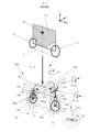
- FIG. 2 is a diagram showing an example of a basic configuration of a vehicle model of a two-wheeled vehicle.
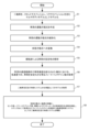
- 1A to 1C are diagrams illustrating an example of a procedure for a modeling method of a motorcycle stable driving control system and an example of a procedure for constructing the motorcycle stable driving control system.
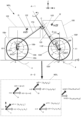
- 1A and 1B are diagrams showing a specific example of a configuration of a vehicle model of a two-wheeled vehicle, and an example in which the velocity and angular velocity at each of a plurality of centers of gravity are displayed by vectors.
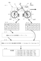
- FIG. 11 is a diagram showing the velocity, angular velocity, acceleration, angular acceleration, acting force, and acting torque of each center of gravity in a vehicle model of a two-wheeled vehicle.
- FIG. 11 is a diagram showing an example of a definition of a generalized speed in a vehicle model of a two-wheeled vehicle, and a method of linearizing a function using a Jacobian at the generalized speed.
- FIG. 13 is a diagram showing linearized action terms in a vehicle model of a two-wheeled vehicle.
- FIG. 13 is a diagram showing linearized inertia terms in a vehicle model of a two-wheeled vehicle.
- FIG. 11 is a diagram showing the velocity, angular velocity, acceleration, angular acceleration, acting force, and acting torque of each center of gravity in a vehicle model of a two-wheeled vehicle.
- FIG. 11 is a diagram showing an example of a definition of a generalized speed in a vehicle model of a two-wheel
- FIG. 13 is a diagram showing an overview of a method for creating a Kane equation of motion for a motorcycle vehicle model using the principle of virtual power, converting the equation of motion into a state equation, determining appropriate feedback gains by root locus analysis, and obtaining a model of a motorcycle stable driving control system.
- 11A and 11B are diagrams showing an example of a simulation result regarding the running stability of a two-wheeled vehicle when the present invention is applied to the two-wheeled vehicle running straight ahead.
- 1A and 1B are diagrams illustrating examples of a handlebar angle and a roll angle when a two-wheeled vehicle is turning.
- FIG. 1 is a diagram showing an example of the configuration of a motorcycle stability control system using an actual motorcycle.
- FIG. 11 is a diagram showing another example of the configuration of a motorcycle stable driving control system using an actual motorcycle.
- FIG. 13 is a diagram showing an example of a configuration for synchronizing updating of the damping force value in the damper with measurement of the extension speed of the suspension.
- FIG. 13 is a diagram illustrating an example of a process for synchronizing updating of the damping force value in the damper with measurement of the extension speed of the suspension.
- FIG. 1 is a diagram showing an example of the configuration of a computer system and a motorcycle stable driving simulator. Note that the motorcycle stable driving simulator may be simply referred to as a simulator.
- the computer system 10 has a computer main unit 12, a monitor 14, a keyboard 16 and a mouse 18 as input devices, and four folders 21, 23, 26, and 28.
- Folders 21 and 23 make up the first folder 20, which is used when obtaining the state equation corresponding to the motorcycle vehicle model and when modifying the state equation.
- Folders 26 and 28 form a second folder 25 that is used when creating a model as a specification for the motorcycle stability control system through simulation with simulator 40, or when editing the model.
- the storage device 30 of the computer main body 12 stores a program 32 that causes the computer, in other words the computer system 10, to operate as a motorcycle stable driving simulator 40 shown in A-2 of FIG. 1, in other words a simulation program 32 for analyzing a motorcycle stable driving control system.
- Folder 21 stores state equations 22 corresponding to the motorcycle stability control system.
- Folder 23 stores data 24 for the state equations.
- Folder 26 stores model 27 as a specification for the motorcycle stability control system, i.e., a program describing the specifications for the motorcycle stability control system. Once the final specifications for the motorcycle stability control system are determined as a result of analysis by simulator 40, the program describing the final specifications becomes the so-called "moving specification" in the model-based development or model-based design of motorcycles.
- Folder 28 stores editing software 29 for model 27.
- the motorcycle stable driving simulator 40 has a signal processing device 44 for feedback gain analysis based on a state equation, an input interface 42 for inputting design parameters of the vehicle model and driving condition parameters of the vehicle model to the signal processing device 44, and an output interface 46 for outputting information on the behavior of the vehicle model in response to the parameters input from the input interface 42.
- Figure 2 is a diagram showing an example of the basic configuration of a vehicle model of a two-wheeled vehicle.
- the X direction indicates the forward direction or the traveling direction
- the Y direction indicates the lateral direction
- the Z direction indicates the up-down direction or the height direction.
- A-1 in Figure 2 shows a schematic example of a conventional vehicle model with one center of gravity.
- the vehicle model of a two-wheeled vehicle has a front wheel 17, a body 15, and a rear wheel 19, and one center of gravity CG is set for the entire vehicle.
- the vehicle model in A-1 in Figure 2 also travels on a flat, even road surface 3.
- A-2 in Figure 2 shows a vehicle model MDL with multiple centers of gravity 1f, 2f, 1r, and 2r, suitable for analysis using multibody dynamics.
- Rotation of the vehicle model MDL around the X-axis is called roll
- rotation around the Y-axis is called pitch
- rotation around the Z-axis is called yaw.
- the motorcycle vehicle model MDL of A-2 in Figure 2 is roughly divided into a front portion and a rear portion.
- the front portion includes a handlebar 121, a steering shaft 120 as the rotation axis of the handlebar 121, a front body 100, and a front tire FT.
- the rear portion includes a rear body 102 and a rear tire RT.
- the front tire FT can be referred to as the front wheel or the front wheel portion.
- the rear tire RT can be referred to as the rear wheel or the rear wheel portion.
- the front tire FT has a pair of front suspensions FR1, FR2, called front forks, which function as dampers, and a tire body 104f.
- suspensions generally have dampers and springs, but the example of A-2 in Figure 2 shows the exterior of the front forks, and the springs are provided inside the front suspensions FR1, FR2.
- the rear tire RT has a pair of rear suspensions RSU1, RSU2.
- Each of the rear suspensions RSU1, RSU2 has a damper Dp and a suspension spring Sp.
- the cushioning characteristics realized by the pair of rear suspensions RSU1, RSU2 are treated as being realized by a single virtual rear suspension 106r.
- the center of gravity of the front tire FT including the front suspension 106f is denoted as 1f, and the mass of the center of gravity is denoted as m1f.
- the center of gravity of the front body 100 is denoted as 2f, and the mass of the center of gravity is denoted as m2f.
- the center of gravity of the rear tire RT including the rear suspension 106r is denoted as 1r, and the mass of the center of gravity is denoted as m1r.
- the center of gravity of the rear body 102 is denoted as 2r, and the mass of the center of gravity is denoted as m2r.
- vehicle model MDL is assumed to travel on an uneven road surface 4.
- the handlebars 121 are shown in the Z-axis direction, i.e., as seen from above, at the bottom right of A-2 in Fig. 2. Using the handlebars position when the motorcycle is moving straight in the X-direction as a reference, it is assumed that the handlebars 121 have rotated a predetermined angle, for example clockwise, around the steering axis 120. In this case, the predetermined angle is referred to as the handlebars angle ⁇ hd.
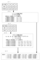
- Figure 3 is a diagram showing an example of the steps in the modeling method of a motorcycle stable driving control system, and an example of the steps leading to the construction of a motorcycle stable driving control system.
- step 1 the motorcycle is modeled as a multibody model including a front suspension and a rear suspension.
- this motorcycle model can be said to be a model that has multiple centers of gravity and includes rigid bodies and elastic or flexible bodies.
- An example of the outline of this model is shown in A-2 in Figure 2. A specific example of this model will be described later using Figure 4.
- step S2 the vehicle's equation of motion is created.
- the Kane equation of motion is used.
- Kane's equations of motion are equations of motion that assume a virtual displacement in the generalized velocity direction and are derived based on the principle of virtual power by focusing on the point where the action force and action torque acting on an object are balanced with the inertial force and inertial torque.
- inertial terms and nonlinear terms can be expressed using a type of unit vector called a partial velocity, which makes it easier to create the equation of motion.
- Generalized velocity can be explained as, for example, the velocity or angular velocity in generalized coordinates, which can be expressed in only one way at any given position on an object as the sum of linear functions.
- step S2 the equation of motion contains a second-order nonlinear term.
- step S3 the vehicle's equation of motion is linearized.
- linearization can be achieved by multiplying a function expressed as a vector by a Jacobian matrix that functions as a differential operator, in other words, a Jacobian.
- a Jacobian it is preferable to use a Jacobian at a generalized speed. This will be described later. Note that Taylor expansion, etc. may also be used.
- step S4 the equation of motion is converted into a state equation to enable analysis using modern control theory.
- step S5 an analysis of the vehicle stability is performed using the root locus.
- the root locus is a locus that the roots of the state equation trace on a complex plane when the feedback gain is changed.
- the feedback control system can be evaluated as stable at the feedback gain value, and if the root locus is outside the region of the left half of the complex plane, the feedback control system can be evaluated as unstable at that feedback gain value.
- step S6 a feedback gain value that can stabilize the vehicle at each speed when the vehicle speed is changed within the desired speed range is obtained.
- step S6 the simulator 40 shown in A-2 of FIG. 1 is used to quickly find optimal feedback gains under various conditions.
- the desired speed range can be set to, for example, a vehicle speed of 1 m/s to 60 m/s, taking into account the actual traveling speed of the actual two-wheeled vehicle.
- step S7 a model is obtained as a specification for the motorcycle stable driving control system. If the analysis by the simulator in step S6 results in a feedback gain that can ensure vehicle stability at all speeds within the desired speed range, the state of the motorcycle stable driving control system in which the feedback gain is obtained is uniquely determined.
- This is the program known as a "moving specification,” or in other words, the model as a specification for the motorcycle stable driving control system.
- step S8 for example, a sensor unit, a power steering unit, and a control signal generation unit for the steering torque actuator are implemented in the actual motorcycle to be controlled, i.e., the actual vehicle, and a motorcycle stable driving control system is constructed as a negative feedback control system that realizes the feedback gain acquired in step S6.
- a motorcycle stable driving control system is constructed as a negative feedback control system that realizes the feedback gain acquired in step S6.
- An example of the constructed motorcycle stable driving control system will be described later with reference to Figures 12 and 13.
- FIG. 4 is a diagram showing a specific example of the configuration of a vehicle model of a two-wheeled vehicle, and an example in which the speed and angular velocity at each of multiple centers of gravity are displayed as vectors.
- A-1 of Figure 4 parts that are common to A-2 of Figure 2 are given the same reference numerals. This is the same in Figures 5 and 6.
- the handlebars have been omitted from the illustration in A-1 of Figure 4. This is the same in Figures 5 and 6.
- the center of gravity of the front tire FT is 1f
- the mass of center of gravity 1f is m1f
- the center of gravity of the front body 100 is 2f
- the mass of center of gravity 2f is m2f
- the center of gravity of the rear tire RT is 1r
- the mass of center of gravity 1r is m1r
- the center of gravity of the rear body 102 is 2r
- the mass of center of gravity 2r is m2r.
- the front body 100 and rear body 102 are treated as rigid bodies.
- the tire body is composed of a rim located on the inside, which is considered to be a rigid body, and an air-filled tube and other components located on the outside that are capable of elastic deformation.
- the tire body taking into account the tire body's characteristic of being able to elastically deform in three dimensions, it can be treated as an elastic or flexible body for convenience.
- the front tire body 104f included in the front tire FT and the rear tire body 104r included in the rear tire RT are modeled as having at least a portion that is elastic or flexible, assuming that they are capable of elastic deformation.
- the front tire body 104f and the rear tire body 104r can be modeled using the magic formula equation.
- the magic formula is an equation obtained by identifying the values of parameters that indicate the characteristics of a tire based on experimental data obtained by a tire testing machine, and is an equation that expresses the force and torque reaction force of the tire from the road surface using trigonometric functions, etc.
- the symbol 105f indicates a spring that represents the elastic characteristics of the front tire body 104f.
- the front suspension 106f includes a spring 110f, in other words a suspension spring 110f, and a front damper 108f.
- the symbol FU indicates an upper point of the front suspension 106f. Note that the front damper may sometimes simply be called a damper.
- the symbol 105r indicates a spring that represents the elastic characteristics of the rear tire body 104r.
- the rear suspension 106r includes a spring 110r, in other words a suspension spring 110r, and a rear damper 108r.
- the suspension spring 110r corresponds to the spring Sp shown in A-2 of FIG. 2 above.
- the rear damper may simply be called the damper.
- the symbol RU indicates the upper point of the rear suspension 106r.
- the caster angle ⁇ cas of the steering axis 120 is determined so that the steering axis 120 and the rear body axis 122 are perpendicular to each other.
- the vector VSf of the vibration component that reflects the damping characteristics of the front suspension 106f, which occurs in the extension direction of the steering shaft 120, and the vector VSr of the vibration component that reflects the damping characteristics of the rear suspension 106r, which occurs in the extension direction of the rear body axle 122, are perpendicular to each other, and the inner product of each vector is zero, so the vectors do not interfere with each other and can be treated as independent. Therefore, the vibration component caused by the front suspension 106f and the vibration component caused by the rear suspension 106r can be treated independently, making analysis easier.
- the symbol A indicates the contact point between the rear tire RT and the ground
- the symbol B indicates the contact point between the front tire FT and the ground
- the symbol B' indicates the intersection point between the steering axis 120 and the ground
- the symbol C indicates the intersection point between the rear body axis 122 and the steering axis 120.
- the front vehicle body 100 rotates around axis CB' when viewed from the rear vehicle body 102, and the front tire body 104f and the rear tire body 104r are each treated as rotating. Furthermore, the front tire body 104f and the rear tire body 104r are each treated as being in contact with the ground at one point, point A or point B, as described above.
- v indicates velocity and w indicates angular velocity. Since these velocities and angular velocities act on each of the centers of gravity 1f, 2f, 1r, and 2f, in order to distinguish which center of gravity the velocity etc. acts on, for example, the velocity and angular velocity for center of gravity 1f are written as v1f and w1f. Similar notations are used for the other centers of gravity.
- u, v, and w are the coordinate axes of generalized velocity in the generalized coordinate system, which correspond to the Cartesian coordinate axes X, Y, and Z in three-dimensional space.
- p, q, and r are coordinate axes of a generalized angular velocity in a generalized coordinate system corresponding to the orthogonal coordinate axes X, Y, and Z in three-dimensional space, respectively.
- the velocity v2r about the center of gravity m2r is expressed as a function of u, v, and w
- the angular velocity w2r is expressed as a function of p, q, and r.
- each center of gravity 1f, 2f, 1r, and 2f is bound by certain constraints and behaves as a single moving body, the state in which the velocity and angular velocity shown in A-2 of Figure 4 act on each center of gravity means that the velocity vmdl and angular velocity wmdl are acting on the vehicle model MDL, and the two are equivalent.
- this "velocity of the vehicle model MDL” is uniquely determined by calculating the vectors of velocities v1f, v2f, v1r, and v2r acting on the centers of gravity 1f, 2f, 1r, and 2r contained in the vehicle model MDL.
- observing or measuring the "velocity of the vehicle model MDL” is synonymous with observing or measuring the "velocity of each center of gravity.” This also applies to the angular velocity.
- observation is used for the analysis of a model of a motorcycle stability control system constructed on a computer
- measurement is used for the analysis of a motorcycle stability control system applied to an actual motorcycle.
- Figure 5 is a diagram showing the velocity, angular velocity, acceleration, angular acceleration, acting force, and acting torque of each center of gravity in a vehicle model of a two-wheeled vehicle.
- parts that are common to Figure 4 are given the same reference numerals.
- A-1 in Figure 5 shows a simplified version of the configuration of A-1 in Figure 4.
- A-2 in Figure 5 shows the velocity and angular velocity for each center of gravity mass m1r, m2r, m1f, and m2f in table format.
- the velocities v1r, v2r, v2f, and v1f each correspond to the velocity of the vehicle or vehicle model, as explained above.
- the angular velocities w1r, w2r, w2f, and w1f each correspond to the angular velocity of the vehicle or vehicle model, as explained above.
- the speed v1r reflects the extension speed of the rear suspension
- v1f reflects the extension speed of the front suspension
- w2f reflects the steering wheel angular speed.
- A-3 in Figure 5 shows in table format the acceleration and angular acceleration for the masses m1r, m2r, m1f, and m2f of each center of gravity.
- A-4 in Figure 5 shows in table format the acting forces and torques for the masses m1r, m2r, m1f, and m2f of each center of gravity.
- T2r and T2f are acting torques that reflect the handle torque input.
- Figure 6 shows an example of the definition of the generalized speed in a vehicle model of a two-wheeled vehicle, and a method of linearizing a function using the Jacobian at the generalized speed.
- A-1 in Figure 6 is the same as A-1 in Figure 5.
- A-2 in Figure 6 shows an example of a definition of a generalized speed for the motorcycle vehicle model MDL shown in A-1 in Figure 6.
- the generalized speed of the vehicle model MDL is defined to include multiple speed components that contribute to the speed of the vehicle in the direction of movement.
- the speedometer installed on the vehicle typically measures the speed based only on, for example, the number of tire revolutions.
- part of the moment generated by turning the steering wheel also contributes to moving the vehicle forward.
- part of the vibration component generated by the extension of the suspension also contributes to moving the vehicle forward.
- A-2 of Figure 6 a function is created that incorporates as many of the various speed components that contribute to the speed in the vehicle's direction of travel as possible as variables, and a generalized speed is defined using this function, making it possible to perform a more detailed analysis of the behavior of the motorcycle in the direction of travel.
- a function Gen is defined that includes as parameters the velocity v2r about the u, v, and w axes acting on the mass m2r of the center of gravity 2r of the rear body, the angular velocity w2r about the p, q, and r axes, the steering wheel angular velocity, the rear suspension extension velocity, the front suspension extension velocity, the angular velocity w1r of the rear tires, and the angular velocity w1f of the front tires.
- this function Gen is defined as the generalized velocity of the vehicle model MDL, or the actual vehicle.
- step S3 in FIG. 3 the equation of motion is linearized.
- linearization is performed by multiplying a function containing nonlinear terms expressed as a vector by the Jacobian, which is a differential operator.
- A-3 in Figure 6 shows an example of expressing multiplying a function by a Jacobian. That is, the operation of multiplying a function f by a Jacobian at the generalized speed above is expressed as Y(f, Gen).
- Figure 7 shows the linearized action terms in a vehicle model of a motorcycle.
- A-1 in Figure 7 is the same as A-1 in Figure 6.
- A-2 in Figure 7 shows in table form the forces and torques acting on the masses m1r, m2r, m2f, and m1f of the centers of gravity 1r, 2r, 2f, and 1f.
- A-3 in Figure 7 is a repeat of the table in A-2 in Figure 5.
- A-4 in Figure 7 shows, as an example, that the action term for mass m1f can be expressed as the sum of the action force F1r and the action torque T1r. The same is true for the other masses.
- A-5 in Figure 7 shows, as an example, an equation showing the action term at generalized velocity for mass m1f.
- This equation uses the expression shown in A-3 in Figure 6, which shows the operation of multiplying a function by a Jacobian. The same applies to other masses.
- the linearized action term of the vehicle model in other words the linearized action term of the vehicle, can be calculated.
- Figure 8 This shows the linearized inertia terms in a vehicle model of a motorcycle.
- A-1 in Figure 8 is a repeat of the table in A-3 in Figure 5.
- A-2 in Figure 8 shows the force of inertia for acceleration at each center of gravity 1r, 2r, 1f, and 2f, in other words, the force of inertia of linear motion.
- the force of inertia of linear motion can be expressed using the dot product of vectors according to the well-known Newton's equation of motion.
- A-3 in Figure 8 is a repeat of the table in A-2 in Figure 5.
- A-4 in Figure 8 shows the force of inertia for angular acceleration at each center of gravity 1r, 2r, 1f, and 2f, in other words, the force of inertia of rotational motion.
- the force of inertia of rotational motion can be expressed using the moment of inertia tensor of each center of gravity and the cross product of a vector, according to the well-known Euler equation of motion.
- A-5 in Figure 8 shows a method for calculating the inertia term of the vehicle model, in other words, the inertia term of the vehicle model.
- the function showing the inertia force for the angular acceleration of each center of gravity obtained in A-4 in Figure 8 is multiplied by the Jacobian to calculate the linearized inertia force of each center of gravity, and the linearized inertia forces of each center of gravity thus obtained are added, i.e., the dot product of the vectors is taken, thereby making it possible to calculate the linearized inertia term of the vehicle model, in other words, the linearized inertia term of the vehicle.
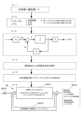
- Figure 9 shows an overview of a method for creating Kane's equation of motion for a motorcycle vehicle model using the principle of virtual power, converting the equation of motion into a state equation, determining appropriate feedback gains through root locus analysis, and obtaining a model of a motorcycle stable driving control system.
- A-1 in Figure 9 shows the Kane equation of motion using the principle of virtual power. According to the principle of virtual power, the action term and inertia term acting on an object are balanced, so this relationship can be used to create the Kane equation of motion.
- the coefficient for the virtual displacement in the generalized velocity direction can be determined unambiguously. Because the Kane equation of motion is a linear equation of motion, it can be converted into a state equation, which is a first-order simultaneous differential equation.
- A-2 in Figure 9 shows the form of the state equation used in the present invention.
- x is the state variable
- u is the input
- y is the output
- a and B are determinants related to the input characteristics of the system
- C is a determinant related to the output characteristics of the system.
- A-3 in Figure 9 is a block diagram of the state equation shown in A-2 in Figure 9.
- the state equation shown in A-2 in Figure 9 shows a feedback control system with a feedback path of feedback gain A. If the feedback gain can be adjusted appropriately, it is possible to construct a negative feedback control system that can converge input fluctuations within a specified time, in other words, a negative feedback control system with stable controllability.
- A-4 in Figure 9 shows that the root locus method is effective for obtaining an appropriate feedback gain, in other words, for analyzing control stability.
- the root locus is the locus on the complex plane that the roots of the state equation trace when the feedback gain is changed. For example, if the root locus is within the left half of the complex plane, the feedback control system can be evaluated as stable at that feedback gain value, and if the root locus is outside the left half of the complex plane, the feedback control system can be evaluated as unstable at that feedback gain value.
- A-4 in Figure 9 shows that linear optimal control LQR (Linear Quadratic Regulation) can be used as a specific method for finding an appropriate feedback gain. Specifically, a solution to the Riccatti equation is found to obtain a control input that can quickly converge the fluctuations in the state variables.
- LQR Linear Quadratic Regulation
- the vehicle speed is changed from 1 m/s to 60 m/s, for example in 1 m/s increments, and the optimal feedback gain is determined for each speed.
- the optimal feedback gain is determined, it can be used to obtain a model of a stable motorcycle driving system that allows a motorcycle to travel stably.
- A-5 in Figure 9 shows an example of the configuration of the model of the obtained motorcycle stable driving system.
- the model 180 of the motorcycle stable driving system has a motorcycle system model MOD1 which is the controlled object, an input system model MOD2 which inputs input variables to the motorcycle system model MOD1, an output system model MOD3 which outputs output variables from the motorcycle system model MOD1, and a feedback system model MOD4 which changes the values of the input variables in the input system model MOD2 by feedback using the feedback gains acquired in step S6 of FIG. 3 based on the output variables.
- the input variable is the steering torque of a motorcycle.
- the two-wheeler system model MOD1 is a model with rear suspension, front suspension, and power steering.
- the motorcycle system model MOD1 is a two-rigid/two-elastic multibody model that includes two rigid bodies, the rear body and the front body, and two elastic bodies, at least parts of which can be considered as elastic bodies, the rear tire including the rear suspension, and the front tire including the front suspension.
- the output system model MOD3 is capable of outputting, or in other words, observable, at least the vehicle speed, vehicle angular velocity, steering wheel angular velocity, and suspension extension speed. More preferably, it is capable of outputting, or in other words, observable, the vehicle acceleration, vehicle angular acceleration, and steering wheel angle.
- the feedback system model MOD4 has a function of realizing an optimal feedback gain for each speed within a predetermined speed range, in other words, a loop gain of a negative feedback loop, of a negative feedback control system that preferably allows the two-wheeled vehicle system model MOD1 to travel stably and autonomously.
- a model 180 of a motorcycle stable driving control system can be created as a negative feedback control system in which the motorcycle system model MOD1 is the control target, the input of the motorcycle system model MOD1 includes at least the steering torque u of the motorcycle, and the output y of the motorcycle system model MOD1 includes at least the speed of the vehicle model, the angular velocity of the vehicle model, the handlebar angular velocity of the handlebar included in the vehicle model, and the suspension extension speed of each of the front suspension and the rear suspension, and negative feedback control is performed based on the output of the vehicle model using the feedback gain obtained in process A-5 of FIG. 9 to control the steering torque as the input u of the motorcycle system model MOD1.
- Figure 10 shows an example of the simulation results for the running stability of a two-wheeled vehicle when the present invention is applied to a two-wheeled vehicle running straight ahead.
- the control stability of a motorcycle system can be analyzed using the root locus of the state equation.
- the root locus is the locus on a complex plane that the roots of the state equation trace when the feedback gain is changed.
- the feedback control system can be evaluated as stable at that feedback gain value.
- the feedback control system can be evaluated as unstable at that feedback gain value.
- the unpatterned region Z1 is a stable region in the complex plane
- the shaded region Z2 is an unstable region in the complex plane.
- the vehicle speed of a motorcycle model is changed from 1 m/s to 60 m/s, the root locus corresponding to each vehicle speed is found, and the results are plotted on a complex plane.
- the root locus is represented by discrete points or a line made up of continuous points.
- the root locus is within the stable region Z1 within the entire range of vehicle speeds from 1 m/s to 60 m/s, and does not enter the unstable region Z2. In other words, it is possible to ensure the running stability of a two-wheeled vehicle traveling straight ahead within the entire range of vehicle speeds.
- Figure 11 shows an example of the handlebar angle and roll angle when a two-wheeled vehicle is turning.
- the state equation that applies when a motorcycle is traveling in a straight line must be modified to take into account the changes in state when the motorcycle turns, or new terms must be added to create a form suitable for analyzing the state of a motorcycle when turning.
- A-1 in Figure 11 shows the motorcycle model shown in A-2 in Figure 2 turning right, viewed from a planar view in the Z-axis direction. Note that for ease of explanation, A-1 in Figure 11 shows a simplified motorcycle model. The handlebars have been omitted from the illustration in A-1 in Figure 11.
- A-2 in Figure 11 shows a front view of the two-wheeled vehicle model in the state of A-1 in Figure 11, as seen from the X-axis direction.
- A-1 and A-2 of FIG. 11 parts common to A-2 of FIG. 2 are given the same reference numerals.
- A-2 of FIG. 11 when a motorcycle turns, the body tilts as it turns.
- the roll angle at this time is ⁇ roll.
- motorcycles Let's take motorcycles as an example. Normally, motorcycles are equipped with a self-steering mechanism that allows the handlebars, or steering, to turn in the direction the body is tilted without the rider even being aware of it.
- the roll angle ⁇ rol for example, must be observed or measured, and because the number of variables to be considered increases, it is necessary to add terms to the state equation or update the coefficient values to values different from those when driving in a straight line.
- the feedback gain required for stable driving can be calculated for all speeds within a specified speed range using a method similar to that previously explained in Figures 2 to 9. This makes it possible to obtain a model of a stable motorcycle driving control system that also handles cornering.
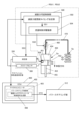
- Figure 12 shows an example of the configuration of a motorcycle stability control system using an actual motorcycle.
- the motorcycle stable driving control system 190 using an actual motorcycle has a motorcycle body 300, and is provided on the motorcycle body 300 with a rear tire sensor unit 301, a rear suspension sensor unit 303, a rear body sensor unit 305, a front body sensor unit 307, a handlebar sensor unit 308, a power steering unit 312, a front suspension sensor unit 311, a front tire sensor unit 313, an engine control unit 315, a measurement unit 350, and an ECU (Electronic Control Unit) 400 as an electronic control device.
- a rear tire sensor unit 301 a rear suspension sensor unit 303, a rear body sensor unit 305, a front body sensor unit 307, a handlebar sensor unit 308, a power steering unit 312, a front suspension sensor unit 311, a front tire sensor unit 313, an engine control unit 315, a measurement unit 350, and an ECU (Electronic Control Unit) 400 as an electronic control device.
- a rear tire sensor unit 301 a rear suspension sensor unit 303, a rear body sensor unit 305,
- the power steering unit 312 has a steering torque sensor 309 and a steering torque actuator 310.
- the engine control unit 315 has a constant torque control unit 317 that controls the output of the engine or electric motor 319, i.e., the torque of the engine or electric motor 319, to a constant value.
- the torque of the engine or electric motor 319 affects the moment acting on each of the four centers of gravity described above. If the torque of the engine or electric motor, i.e. the moment, fluctuates with changes in the rotation speed of the engine or electric motor 319, i.e. changes in the vehicle speed of the two-wheeled vehicle, it also affects the generalized speed shown in A-2 of FIG. 6, and the error associated with the linearization of the equation of motion increases, which is one of the factors that reduces the control accuracy of the negative feedback control. Therefore, constant torque control is implemented to stabilize the output of the engine or electric motor 319 and suppress the reduction in the control accuracy of the negative feedback control.
- the rear tire sensor unit 301 detects the rear tire speed and rear tire angular velocity, and supplies detection signals to the measurement unit 350. However, it may also be possible to detect the rear tire acceleration and rear tire angular acceleration using a 6-axis MEMS (Micro Electro Mechanical Systems) sensor or the like.
- MEMS Micro Electro Mechanical Systems
- the rear suspension sensor unit 303 detects the rear suspension extension speed and supplies the detection signal to the measurement unit 350.
- the rear body sensor unit 305 detects the rear body speed and rear body angular velocity, and supplies the detection signals to the measurement unit 350.
- a 6-axis MEMS sensor or the like may be used to detect the rear body acceleration and rear body angular acceleration as well.
- the front body sensor unit 307 detects the front body speed and the front body angular velocity, and supplies the detection signals to the measurement unit 350.
- a 6-axis MEMS sensor or the like may be used to detect the front body acceleration and the front body angular acceleration as well.
- the steering wheel sensor unit 308 detects the steering wheel angle and steering wheel angular velocity, and supplies the detection signals to the measurement unit 350.
- a 6-axis MEMS sensor or the like may be used to detect steering wheel acceleration and steering wheel angular acceleration as well.
- the power steering unit 312 detects the steering torque applied around the steering shaft, for example, the handle torque or the steering torque related to the steering shaft, using a steering torque sensor 309, and supplies the detection signal to the measurement unit 350.
- a steering torque sensor 309 for example, a torsion bar sensor can be used.
- the steering torque actuator 310 included in the power steering unit 312 can be configured, for example, as a torsion bar actuator, a magnetostrictive actuator, etc.
- the steering torque actuator 310 is operated by a steering torque actuator control signal DCT that is generated and output by a steering torque actuator control signal generating unit 408 (described later) provided in the ECU 400, and applies the torque required to prevent the motorcycle from tipping over, i.e., the moment for preventing tipping over, to the handlebars, steering shaft, etc.
- the front suspension sensor unit 311 detects the extension speed of the front suspension and supplies the detection signal to the measurement unit 350.
- the front tire sensor unit 313 detects the front tire speed and the front tire angular velocity, and supplies the detection signals to the measurement unit 350. However, it may also be possible to detect the front tire acceleration and the front tire angular acceleration using a 6-axis MEMS sensor or the like.
- the measurement unit 350 for example, amplifies the various detection signals that are input, converts them into digital form, samples them, and supplies the resulting digital signal to the ECU 400.
- the output corresponding to the input of various detection signals other than the steering torque detection signal is represented as y(t), and the output corresponding to the input of the steering torque detection signal is represented as s(t).
- y(t) is the "various sensor signal values” that vary over time
- s(t) is the “steering torque value” around the steering axis of the motorcycle that varies over time.
- the ECU 400 has a microcomputer 402 and a power steering control unit 403 provided in the microcomputer 402.
- the microcomputer 402 functions as a motorcycle stability control device.
- the power steering control unit 403 has an error detection unit 406 equipped with a comparison unit 407, and a steering torque actuator control signal generation unit 408.
- the comparison unit 407 included in the error detection unit 406 compares the steering torque value S(t) sent from the measurement unit 350 with the target value sd of the negative feedback control, and outputs the difference as the error e(t).
- the error e(t) can be expressed as sd-s(t).
- the steering torque actuator control signal generation unit 408 has a generalized speed calculation unit 410 and a steering torque actuator control signal calculation unit 412.
- the generalized speed GEN is defined as a function that includes multiple speed components related to the direction of movement of the two-wheeled vehicle.
- the generalized speed calculation unit 410 calculates the current generalized speed of the vehicle based on the various sensor signal values y(t) sent from the measurement unit 350.
- the coefficient k corresponding to the optimal feedback gain corresponding to the calculated generalized speed is uniquely determined. That is, as explained above, the nonlinear equation of motion that describes the vehicle's behavior is linearized under the condition that the generalized speed is constant and does not fluctuate over an extremely short period of time. That is, the feedback gain at the generalized speed is determined by linearly approximating the quadratic function to a linear equation, converting it into a state equation, and solving the state equation to find the eigenvalues. The coefficient that corresponds to this feedback gain is the coefficient k shown in FIG. 12.
- This control input u(t) causes the motorcycle stable driving control system 190 to function as a negative feedback control system, and is a control input that can quickly converge, within a specified time, any fluctuations that occur in the steering torque, which is the input to the system 190.
- This control input u(t) is given to the steering torque actuator 310 included in the power steering unit 312, which performs negative feedback control and ensures stable driving of the motorcycle.
- Fig. 13 is a diagram showing another example of the configuration of a motorcycle stable driving control system using an actual motorcycle.
- the same reference numerals are used to designate the same parts as in Fig. 12.
- the damping force is variably controlled in at least one of the front suspension 106f included in the front tire FT of the motorcycle and the rear suspension 106r included in the rear tire RT.
- electronic variable damping force control is implemented in at least one of the dampers of the front suspension 106f and the rear suspension 106r.
- the damping force value is updated when the spring included in the suspension is fully compressed, and the extension speed of the suspension is measured by measuring the suspension extension speed in synchronization with the update of the damping force value, thereby synchronizing the update of the damping force value with the measurement of the extension speed of the suspension.
- the damping force of the damper in the suspension can be variably controlled in a variety of ways, including setting the damping force value lower than normal, or conversely, setting the damping force value higher than normal, or implementing variable damping force control by step, which switches the damping force value generated during the compression and expansion steps of the spring.
- updating the damping force value changes the damping characteristics of the suspension, and this change in damping characteristics is likely to affect the overall behavior of the motorcycle.
- the rear suspension sensor unit 303 and the front suspension sensor unit 311 each supply a notification signal TM of the timing to update the damping force value to the measurement unit 350.
- the other configuration is the same as the example of FIG. 12.
- the measurement unit 350 synchronizes the sampling period by A/D conversion of at least one of the rear suspension extension speed and the front suspension extension speed, in other words, the start timing of the period during which the suspension extension speed can be measured, with the damping direct value update timing. This makes it possible to accurately measure and observe the suspension extension speed, which corresponds to the change in the damping force characteristics due to the update of the damper's damping force value.
- FIG. 14 is a diagram showing an example of a configuration for synchronizing the update of the damping force value in the damper with the measurement of the extension speed of the suspension.
- parts that are common to the previous figures are given the same reference numerals.
- FIG. 14 shows an example of a configuration for achieving synchronous control in a rear suspension. The following explanation can also be applied to a front suspension.
- the rear suspension has a pair of rear suspensions RSU1 and RSU2, each of which has the same damping force characteristics and both of which are electronically variable damping force controlled.
- Each of the pair of rear suspensions RSU1, RSU2 has a spring, in other words a suspension spring Sp, and a damper Dp.
- a variable damping force control section 500 is provided to control the flow rate of hydraulic oil in this flow control valve 460 and variably control the damping force.
- the variable damping force control unit 500 has a damping force value update timing determination unit 502 and a flow control valve drive unit 504.
- the damping force value update timing determination unit 502 notifies the flow control valve drive unit 504 of the damping force update value information SS1 at the detection timing, and the flow control valve drive unit 504 outputs a control signal SS2 at the timing when it receives the notification, and controls the flow control valve 460 to change the damping force value.
- damping force value is updated when the spring Sp is fully compressed. Because updating the damping direct value while the spring Sp is being compressed and moving, or while the spring Sp is being extended, would not allow for accurate switching of the damping force value. Therefore, the damping force value is updated in sync with the point at which the spring Sp is fully compressed.
- the measuring unit 350 has an internal A/D converter and measures the suspension extension speed by sampling the suspension extension speed detection signal supplied from the suspension extension speed sensor 456.
- this measurement method is only one example and is not limited to this.
- a measurement method in which the suspension extension speed sensor 456 is directly controlled to enable detection by the suspension extension speed sensor 456 at the measurement timing may also be used.
- the measurement is performed within the period during which the suspension extension speed can be measured. This will be described later with reference to FIG. 15.
- the start timing of the measurement period is synchronized with the update timing of the damping force value.
- the measuring unit 350 supplies a detection signal of the suspension extension speed to the microcomputer 402 in the ECU 400.
- the microcomputer 402 serving as the motorcycle stable driving control device is provided with a power steering control unit 403, and this power steering control unit 403 is provided with a steering torque actuator control signal generation unit 408.
- the steering torque actuator control signal generating unit 408 performs the processing required for power steering control, such as calculating the generalized speed, based on the accurate detection signal of the suspension extension speed, to generate a steering torque actuator control signal DTC, and supplies this steering torque actuator control signal DTC to the steering torque actuator 310 of the power steering unit 312. This realizes highly accurate power steering control that takes into account the update of the suspension damping force value.
- FIG. 15 is a diagram showing an example of a process for synchronizing the update of the damping force value in the damper with the measurement of the extension speed of the suspension.
- parts that are the same as those in FIG. 14 are given the same reference numerals. The operation of each part is explained in FIG. 14, so an explanation of the operation of each part will be omitted.
- the spring Sp is in a fully extended state at time t0, and compression of the spring Sp begins from this time t0.
- the spring Sp is in a fully contracted state, and at this timing, the period during which the suspension extension speed can be measured begins.
- the spring Sp returns to a fully extended state.
- the period T from time t1 to t2 is the period during which the suspension extension speed can be measured.
- the measurement unit 350 can measure the suspension extension speed during at least a portion of this suspension extension speed measurement period T, or at a specified point in time within that period T. In this way, it is possible to synchronize the update of the damping force value in the damper with the measurement of the suspension extension speed.
- the measurement unit 350 outputs a measurement value of the suspension extension speed, in other words, a detection signal of the suspension extension speed.
- a method for modeling a motorcycle stable driving control system includes a first step (S1) of obtaining a vehicle model in which a motorcycle is modeled into a model having a center of gravity (2f) of a front body, a center of gravity (2r) of a rear body, a center of gravity (1f) of a front tire (FT) including a front tire body (104f) and a front suspension (106f), and a center of gravity (1r) of a rear tire (RT) including a rear tire body (104r) and a rear suspension (106r);
- the method includes a second step (S2, S3) of creating a linear equation of motion for the vehicle model (MDL) on the condition that the inertia term is balanced; a third step (S4) of converting the linear equation of motion into a state equation; a fourth step (S5, S6) of acquiring a feedback gain capable of stabilizing the running of the vehicle model at a speed within a predetermined speed range by analyzing the
- the model (180) of the motorcycle stable driving control system created in the fifth step may have a motorcycle system model (MOD1) corresponding to the motorcycle to be controlled, an input system model (MOD2) that inputs input variables to the motorcycle system model, an output system model (MOD3) that outputs output variables from the motorcycle system model, and a feedback system model (MOD4) that changes the values of the input variables in the input system model by feedback using the feedback gains obtained in the fourth step based on the output variables.
- a motorcycle system model MOD1 corresponding to the motorcycle to be controlled
- an input system model MOD2
- MOD3 that outputs output variables from the motorcycle system model
- a feedback system model MOD4 that changes the values of the input variables in the input system model by feedback using the feedback gains obtained in the fourth step based on the output variables.
- the motorcycle stable driving control system is divided into multiple models, so in model-based development, the motorcycle stable driving control system can be easily designed by replacing each model with an actual part.
- a vehicle model is the control target
- the input of the vehicle model includes at least the steering torque in the vehicle model
- the output of the vehicle model includes at least the speed of the vehicle model, the angular velocity of the vehicle model, the steering wheel angular velocity of the handle included in the vehicle model, and the suspension extension speed of each of the front suspension and the rear suspension.
- negative feedback control is performed using the feedback gain obtained in the fourth step to control the steering torque as an input to the vehicle model.
- the steering torque acting on the handles and steering shaft of the motorcycle can be appropriately generated while taking into full consideration the characteristics of the suspension, etc., and the running of the motorcycle can be stabilized using power steering technology.
- a condition when creating a linear equation of motion for the vehicle model, a condition may be applied in which the engine or motor (319) included in the actual two-wheeled vehicle corresponding to the vehicle model is subjected to constant torque control so that the torque is constant even if the rotation speed fluctuates.
- constant torque control can reduce the moment and other forces generated in the vehicle body in response to changes in the rotation speed of the engine or motor of the motorcycle, thereby improving the accuracy of analysis of the stable driving controllability of the motorcycle.
- a generalized velocity of the vehicle model is defined by a function including, as variables, a first velocity component occurring in the direction of movement of the vehicle model due to translational motion without rotation of the vehicle model, and a second velocity component occurring in the direction of movement of the vehicle model due to rotational motion of the vehicle model, and a linearized action term and a linearized inertia term are calculated by multiplying each of the nonlinear action terms and inertia terms included in the nonlinear equation of motion by a Jacobian matrix at the generalized velocity, and a linear equation of motion may be created under the condition that the linearized action term and the linearized inertia term are balanced.
- the average speed is defined by comprehensively taking into account the speed components resulting from translational motion and rotational motion that occur in the direction of movement of the vehicle model, making it possible to accurately analyze the complex behavior of a two-wheeled vehicle by taking into account vibrations and other factors that accompany rotation.
- the linearization process is performed under the condition that the average speed is constant, so the amount of information lost due to this linearization, i.e., first-order approximation, can be kept to a minimum, making it possible to prevent a decrease in analysis accuracy.
- the damper (Dp) included in at least one of the front suspension and the rear suspension has a variably controlled damping force
- the suspension (RSU1, RSU2, FR1, FR2) which includes a damper whose damping force is variably controlled as a component is a variable damping suspension.
- the damping force value when observing the suspension extension speed, if the suspension is a variable damping suspension, the damping force value is updated when the spring included in the variable damping suspension is fully compressed, and the suspension extension speed is observed in synchronization with this update, making it possible to accurately observe the suspension extension speed corresponding to the updated damping force value.
- the changes in the damping force value can be accurately reflected, making it possible to more accurately observe, analyze, evaluate, etc. the complex behavior of the two-wheeled vehicle.
- it is possible to accurately generate the steering torque for power steering which is necessary for autonomous stable driving control of a two-wheeled vehicle. This makes it possible to evaluate and analyze the autonomous stable driving controllability of a wide variety of motorcycles. It also greatly improves the versatility of model-based development. It also improves the accuracy of power steering technology for motorcycles.
- the motorcycle stable driving simulator (40) has a signal processing device (44) that performs signal processing for obtaining a feedback gain in the fourth step of the modeling method for a motorcycle stable driving control system in the first aspect, an input interface (42) that inputs design parameters of the vehicle model and driving condition parameters of the vehicle model to the signal processing device, and an output interface (46) that outputs information on the behavior of the vehicle model with respect to the parameters input from the input interface.
- the seventh aspect enables detailed analysis and evaluation of appropriate feedback gains for motorcycles that exhibit complex behavior, which could not be scientifically verified in the past. This makes it possible to speed up the design of motorcycles with autonomous driving functions.
- the program causes a computer to operate as the two-wheeled vehicle stable driving simulator of the seventh aspect.
- a simulator can be constructed by a program, making it easier to implement.
- the motorcycle stable driving control system (190) has an actual motorcycle (300), a power steering unit (312) that is attached to the actual motorcycle and includes as a component a steering torque actuator (310) that generates a steering torque in the motorcycle, a measurement unit (350) that performs measurement processing based on the output of multiple sensor units (301, 303, 305, 307, 308, 311, 313) that are attached to the actual motorcycle, and a power steering control unit (403) that is attached to the motorcycle and has a steering torque actuator control signal generation unit (408) that generates a control signal for the steering torque actuator based on the output of the measurement unit.
- a high-performance motorcycle stable driving control system for an actual motorcycle can be realized using a model-based development method.
- the measurement unit (350) may measure the rear tire speed, rear tire angular velocity, rear body speed, rear body angular velocity, front tire speed, front tire angular velocity, front body speed, front body angular velocity, handlebar angular velocity of the handlebars of the real motorcycle, extension speed of the front suspension of the real motorcycle, and suspension extension speed of the rear suspension of the real motorcycle.
- the steering torque acting on the handles and steering shaft of the motorcycle can be appropriately generated while taking into full consideration the characteristics of the suspension, and power steering technology can be used to stabilize the running of the motorcycle.
- each of the front suspension (FR1, FR2) and rear suspension (RSU1, RSU2) provided on the actual motorcycle, i.e., the motorcycle body (300), has a spring (Sp) and a damper (Dp), and at least one of the front suspension and the rear suspension further has a variable damping force control unit (500) that variably controls the damping force of the damper, and when a suspension including a damper whose damping force is variably controlled as a component is defined as a variable damping force suspension, the variable damping force control unit (500) updates the damping force value when the spring (Sp), which is a component of the variable damping force suspension, is fully compressed, and the measurement unit (350), when measuring the suspension extension speed of the variable damping force suspension, may measure the suspension extension speed in synchronization with the update of the damping force value in the variable damping force control unit (500).
- rear vehicle body 104f, 104r... tire body, 105f... spring representing the elasticity characteristics of the front tire body, 105r... spring representing the elasticity characteristics of the rear tire body, 106f... one virtual front suspension (front suspension), 106r... one virtual rear suspension (rear suspension), 108f... front damper, 108r... rear damper, 110f, 110r... spring (suspension spring), 120... steering shaft, 121... handle, 122... rear vehicle axle, 180... model of motorcycle stable running system, 190... motorcycle stable running control system, 300... motorcycle body, 301... rear tire sensor unit, 303... rear suspension sensor unit, 305... rear vehicle body sensor unit, 307... front vehicle body sensor unit, 308...
Landscapes
- Engineering & Computer Science (AREA)
- Mechanical Engineering (AREA)
- Transportation (AREA)
- Chemical & Material Sciences (AREA)
- Combustion & Propulsion (AREA)
- Automation & Control Theory (AREA)
- Physics & Mathematics (AREA)
- Mathematical Physics (AREA)
- Human Computer Interaction (AREA)
- Steering Devices For Bicycles And Motorcycles (AREA)
- Axle Suspensions And Sidecars For Cycles (AREA)
- Steering Control In Accordance With Driving Conditions (AREA)
- Control Of Driving Devices And Active Controlling Of Vehicle (AREA)
- Tires In General (AREA)
Abstract
Description
なお、以下の説明において、パワーステアリングの手法として、例えば、ハンドル、及びハンドルを回転させる回転軸、言い換えればステアリング軸の少なくとも一方に、トーションバーアクチュエータ等によって操舵トルクを加える技術を想定する。ここで、ハンドル角やステアリング角等は、名称は異なるが、広義には、二輪車の操舵に関係する操舵角である点で共通する。
また、この特許文献6では、速度センサや、慣性センサ等、種々のセンサが使用されることが記載されているが、これらの多数のセンサをどのように用いて、自律安定走行を可能とする負帰還制御システムを構築するかについては、何ら記載がない。
よって、非剛体要素、例えば所定の運動に関して弾性体、あるいは可撓体とみなされる要素が含まれる運動系の解析には適用できない。
なお、所定の運動に関して弾性体、あるいは可撓体とみなされる要素が含まれる制御対象としては、例えば、剛体の車体系と、この剛体の車体系を支持すると共に、例えば上下方向の振動に関しては弾性体、あるいは可撓体とみなされ得るタイヤ系と、を含む二輪車システム等が想定され得る。
本発明は、これらの知見に基づいて完成された。
図1を参照する。図1は、コンピュータシステム、及び二輪車安定走行シミュレータの構成の一例を示す図である。なお、二輪車安定走行シミュレータは、単にシミュレータと記載する場合がある。
フロント車体100の重心を2fと表記し、その重心の質量をm2fと表記する。
リヤサスペンション106rを含むリヤタイヤRTの重心を1rと表記し、その重心の質量をm1rと表記する。
リヤ車体102の重心を2rと表記し、その重心の質量をm2rと表記する。
ケインの運動方程式では、部分速度と称される一種の単位ベクトルを用いて慣性項や非線形項を表現することができ、運動方程式の作成が容易化される。
ここで、根軌跡は、フィードバックゲインを変化させたときに、状態方程式の根が複素平面上で描く軌跡である。
図4のA-2では、重心m2rについての速度v2rについては、u、v、wの関数として表記し、角速度w2rについては、p、q、rの関数として表記している。
他の重心m2f、m1r、m1fについても同様であるが、但し、どの重心についての速度、角速度であるのかを区別できるようにするために、u、v、w、及び、p、q、rの各々に、各重心の符号を付加して示している。
また、モデルMDL全体としての速度、角速度についても同様であるが、4つの重心の速度、角速度と区別できるように、モデルMDLの速度、角速度については、u、v、w、及び、p、q、rの各々に、mdlという符号を付加して示している。
なお、コンピュータ上に構築される二輪車安定走行制御システムのモデルの解析等に関しては、「観測」という用語を使用し、実機の二輪車に適用される二輪車安定走行制御システムの解析等に関しては、「測定」という用語を使用する。
次に、図13を参照する。図13は、実機の二輪車を用いた、二輪車の安定走行制御システムの構成の他の例を示す図である。図13において、図12と共通する部分には同じ符号を付している。
よって、例えば、二輪車の安定走行制御について、科学的、かつ客観的な解析や評価が可能となる。
また、例えば、自律安定走行する二輪車を、モデルベース開発の手法を用いて、効率的に設計することが可能となる。
本態様の技術を用いると、減衰力可変制御を実施する電子制御式サスペンションを備える二輪車についても、その減衰力値の変化を的確に反映させて、二輪車の複雑な挙動をより正確に観測、解析、評価等することができる。
また、二輪車の自律安定走行制御に必要な、パワーステアリング用の操舵トルクを的確に発生させることができる。
よって、広範な種類の二輪車の自律安定走行制御性等を評価、解析することができる。また、モデル化ベース開発の汎用性を大幅に向上させることができる。また、二輪車におけるパワーステアリング技術の精度を向上させることができる。
本態様の技術を用いると、減衰力可変制御を実施する電子制御式サスペンションを備える二輪車についても、その減衰力値の変化を的確に反映させて、二輪車の複雑な挙動をより正確に観測、解析、評価等することができる。
また、二輪車の自律安定走行制御に必要な、パワーステアリング用の操舵トルクを的確に発生させることができる。
よって、広範な種類の二輪車の自律安定走行制御性等を評価、解析することができる。また、モデル化ベース開発の汎用性を大幅に向上させることができる。また、二輪車におけるパワーステアリング技術の精度を向上させることができる。
Claims (14)
- 二輪車を、フロント車体の重心、リヤ車体の重心、フロントタイヤ本体及びフロントサスペンションを含むフロントタイヤの重心、及び、リヤタイヤ本体及びリヤサスペンションを含むリヤタイヤの重心を有するモデルにモデル化した車両モデルを取得する第1のステップと、
前記重心の各々に働く作用力の総計を示す作用項と、前記重心の各々に働く慣性力の総計を示す慣性項とが釣り合うことを条件として、前記車両モデルについての線形の運動方程式を作成する第2のステップと、
前記線形の運動方程式を状態方程式に変換する第3のステップと、
前記状態方程式の根軌跡による解析によって、所定の速度範囲内の速度における、前記車両モデルの走行を安定化させ得るフィードバックゲインを取得する第4のステップと、
前記第4のステップにおいて取得されたフィードバックゲインによる負帰還制御を実施する二輪車安定走行制御システムのモデルを作成する第5のステップと、
を含む、二輪車安定走行制御システムのモデル化方法。 - 前記第5のステップにて作成される前記二輪車安定走行制御システムのモデルは、
制御対象である前記二輪車に対応する二輪車システムのモデルと、
前記二輪車システムのモデルに入力変数を入力する入力系のモデルと、
前記二輪車システムのモデルから出力変数を出力する出力系のモデルと、
前記出力変数に基づく、前記第4のステップにて取得されたフィードバックゲインによるフィードバックによって、前記入力系のモデルにおける前記入力変数の値を変更するフィードバック系のモデルと、
を有する、請求項1に記載の二輪車安定走行制御システムのモデル化方法。 - 前記二輪車安定走行制御システムのモデルの作成に際しては、
前記車両モデルを制御対象とし、
前記車両モデルの入力に少なくとも、前記車両モデルにおける操舵トルクが含まれ、
前記車両モデルの出力に少なくとも、前記車両モデルの速度、前記車両モデルの角速度、前記車両モデルに含まれるハンドルについてのハンドル角速度、前記フロントサスペンション及び前記リヤサスペンションの各々におけるサスペンション伸長速度が含まれ、
前記車両モデルの出力に基づいて、前記第4のステップにおいて取得されたフィードバックゲインによる負帰還制御を実施して、前記車両モデルの入力としての前記操舵トルクを制御する、
請求項1に記載の二輪車安定走行制御システムのモデル化方法。 - 前記第2のステップにおいて、
前記車両モデルについての線形の運動方程式を作成するに際し、
前記車両モデルに対応する実機の二輪車に含まれるエンジン又はモータが、回転数が変動してもトルクが一定になるように定トルク制御される、という条件が適用される、
請求項1に記載の二輪車安定走行制御システムのモデル化方法。 - 前記第2のステップにおいて、
車両モデルについての線形の運動方程式を作成するに際し、
前記車両モデルの回転を伴わない並進運動による、前記車両モデルの移動方向に生じる第1の速度成分、及び、前記車両モデルの回転運動による、前記車両モデルの移動方向に生じる第2の速度成分の各々を変数として含む関数にて、前記車両モデルの一般化速度を定義すると共に、
非線形の運動方程式に含まれる非線形の作用項、及び慣性項の各々に、前記一般化速度でのヤコビ行列を掛け算することで、線形化された作用項、及び線形化された慣性項を算出し、
前記線形化された作用項と、前記線形化された慣性項とが釣り合うことを条件として、前記線形の運動方程式を作成する、
請求項1に記載の二輪車安定走行制御システムのモデル化方法。 - 前記フロントサスペンション、及び前記リヤサスペンションの少なくとも一方に含まれるダンパーは、減衰力が可変に制御されるものとし、
減衰力が可変に制御されるダンパーを構成要素として含むサスペンションを、減衰力可変サスペンションとする場合において、
前記減衰力可変サスペンションについての、前記サスペンション伸長速度の観測に際しては、
前記減衰力可変サスペンションの構成要素であるバネが縮みきったときに減衰力値を更新するものとし、かつ、前記減衰力値の更新に同期させて、前記サスペンション伸長速度を観測する、
請求項1に記載の二輪車安定走行制御システムのモデル化方法。 - 請求項1に記載の二輪車安定走行制御システムのモデル化方法での前記第4のステップにおける前記フィードバックゲインの取得用の信号処理を実施する信号処理装置と、
前記車両モデルの設計パラメータ、及び前記車両モデルの走行条件パラメータを、前記信号処理装置に入力する入力インタフェースと、
前記入力インタフェースから入力されるパラメータに対する、前記車両モデルの挙動の情報を出力する出力インタフェースと、
を有する、二輪車安定走行シミュレータ。 - コンピュータを、請求項7に記載の二輪車安定走行シミュレータとして動作させるプログラム。
- 実機の二輪車と、
前記実機の二輪車に取り付けられる、前記実機の二輪車における操舵トルクを発生させる操舵トルクアクチュエータを構成要素として含むパワーステアリング部と、
前記実機の二輪車に取り付けられる複数のセンサ部の出力に基づく測定処理を実施する測定部と、
前記二輪車に取り付けられ、かつ、前記測定部の出力に基づいて前記操舵トルクアクチュエータの制御信号を生成する操舵トルクアクチュエータ制御信号生成部を有するパワーステアリング制御部と、
を有する二輪車安定走行制御システム。 - 前記測定部は、
前記実機の二輪車におけるリヤタイヤ速度、リヤタイヤ角速度、リヤ車体速度、リヤ車体角速度、フロントタイヤ速度、フロントタイヤ角速度、フロント車体速度、フロント車体角速度、前記実機の二輪車におけるハンドルのハンドル角速度、前記実機の二輪車におけるフロントサスペンションの伸長速度、及び、前記実機の二輪車におけるリヤサスペンションのサスペンション伸長速度を測定する、
請求項9に記載の二輪車安定走行制御システム。 - 前記実機の二輪車に備わるフロントサスペンション、及びリヤサスペンションの各々は、バネと、ダンパーとを有すると共に、
前記フロントサスペンション及び前記リヤサスペンションの少なくとも一方において、前記ダンパーの減衰力を可変に制御する減衰力可変制御部、をさらに有し、
減衰力が可変に制御されるダンパーを構成要素として含むサスペンションを、減衰力可変サスペンションとする場合に、
前記減衰力可変制御部は、
前記減衰力可変サスペンションの構成要素であるバネが縮みきったときに減衰力値を更新すると共に、
前記測定部は、
前記減衰力可変サスペンションについてのサスペンション伸長速度の測定に際しては、
前記減衰力可変制御部における前記減衰力値の更新に同期させて、前記サスペンション伸長速度を測定する、
請求項9に記載の二輪車安定走行制御システム。 - 前記実機の二輪車は、移動している前記実機の二輪車の車両に含まれるエンジン又はモータを、回転数に対してトルクが一定になるように定トルク制御する定トルク制御部を有し、
前記二輪車安定走行制御システムが動作しているときは、前記定トルク制御部による定トルク制御が実施される、
請求項9に記載の二輪車安定走行制御システム。 - 請求項9乃至請求項12の何れか1項に記載の二輪車安定走行制御システムにおける、前記パワーステアリング制御部として機能する二輪車安定走行制御装置。
- 前記測定部の出力に基づき、前記操舵トルクの、目標値との誤差を検出する誤差検出部と、
検出された操舵トルクの誤差を抑制するように、前記操舵トルクアクチュエータ制御信号を生成する前記操舵トルク制御信号生成部と、
を有する、
請求項13に記載の二輪車安定走行制御装置。
Priority Applications (4)
| Application Number | Priority Date | Filing Date | Title |
|---|---|---|---|
| JP2023534175A JP7356621B1 (ja) | 2023-06-05 | 2023-06-05 | 二輪車安定走行制御システムのモデル化方法、二輪車安定走行シミュレータ、及びプログラム |
| PCT/JP2023/020767 WO2024252449A1 (ja) | 2023-06-05 | 2023-06-05 | 二輪車安定走行制御システムのモデル化方法、二輪車安定走行シミュレータ、プログラム、二輪車安定走行制御システム、及び二輪車安定走行制御装置 |
| EP23940557.4A EP4722091A1 (en) | 2023-06-05 | 2023-06-05 | Method of modeling two-wheeler stable travel control system, two-wheeler stable travel simulator, program, two-wheeler stable travel control system, and two-wheeler stable travel control device |
| JP2023126193A JP7476408B1 (ja) | 2023-06-05 | 2023-08-02 | 二輪車安定走行制御システム、及び二輪車安定走行制御装置 |
Applications Claiming Priority (1)
| Application Number | Priority Date | Filing Date | Title |
|---|---|---|---|
| PCT/JP2023/020767 WO2024252449A1 (ja) | 2023-06-05 | 2023-06-05 | 二輪車安定走行制御システムのモデル化方法、二輪車安定走行シミュレータ、プログラム、二輪車安定走行制御システム、及び二輪車安定走行制御装置 |
Publications (1)
| Publication Number | Publication Date |
|---|---|
| WO2024252449A1 true WO2024252449A1 (ja) | 2024-12-12 |
Family
ID=88198232
Family Applications (1)
| Application Number | Title | Priority Date | Filing Date |
|---|---|---|---|
| PCT/JP2023/020767 Ceased WO2024252449A1 (ja) | 2023-06-05 | 2023-06-05 | 二輪車安定走行制御システムのモデル化方法、二輪車安定走行シミュレータ、プログラム、二輪車安定走行制御システム、及び二輪車安定走行制御装置 |
Country Status (3)
| Country | Link |
|---|---|
| EP (1) | EP4722091A1 (ja) |
| JP (2) | JP7356621B1 (ja) |
| WO (1) | WO2024252449A1 (ja) |
Citations (15)
| Publication number | Priority date | Publication date | Assignee | Title |
|---|---|---|---|---|
| JPS63312271A (ja) | 1987-06-15 | 1988-12-20 | Honda Motor Co Ltd | 車両の運動制御方法 |
| JP2004338507A (ja) | 2003-05-14 | 2004-12-02 | Yamaha Motor Co Ltd | 自動二輪車 |
| JP2005349927A (ja) * | 2004-06-09 | 2005-12-22 | Yamaha Motor Co Ltd | 鞍乗り型車両 |
| WO2006012709A1 (en) | 2004-08-06 | 2006-02-09 | Vrije Universiteit Brussel | System and method for simulating motion of a multibody system |
| JP2009132271A (ja) * | 2007-11-30 | 2009-06-18 | Honda Motor Co Ltd | 自動二輪車のステアリング補助システム |
| JP4605227B2 (ja) | 2005-12-01 | 2011-01-05 | 株式会社村田製作所 | 転倒防止制御装置 |
| JP2013060187A (ja) | 2011-09-09 | 2013-04-04 | Robert Bosch Gmbh | 二輪車のための操舵支援システムならびに操舵支援システムのための制御装置 |
| WO2014054697A1 (ja) * | 2012-10-02 | 2014-04-10 | 学校法人日本大学 | 自動車の運動制御方法、自動車の運動制御装置及び自動車 |
| JP2014078090A (ja) | 2012-10-10 | 2014-05-01 | Mitsubishi Electric Corp | 剛体多体系の運動方程式導出装置および剛体多体系の運動方程式導出方法 |
| JP2014091386A (ja) * | 2012-11-01 | 2014-05-19 | Honda Motor Co Ltd | 移動体 |
| JP2015158390A (ja) | 2014-02-24 | 2015-09-03 | 富士アイティ株式会社 | 制御対象モデル及び姿勢制御方法 |
| JP6081238B2 (ja) | 2013-03-12 | 2017-02-15 | 本田技研工業株式会社 | 移動体 |
| JP2019119447A (ja) | 2018-01-08 | 2019-07-22 | ヤマハ発動機株式会社 | リーン可能な車両の運転性能を向上させるためのシステムおよび方法 |
| JP2020117196A (ja) * | 2019-01-28 | 2020-08-06 | 日立オートモティブシステムズ株式会社 | 車両運動状態推定装置 |
| JP2020124960A (ja) * | 2019-02-01 | 2020-08-20 | トヨタ自動車株式会社 | 車両用制動力制御装置 |
Family Cites Families (2)
| Publication number | Priority date | Publication date | Assignee | Title |
|---|---|---|---|---|
| JP2017109675A (ja) * | 2015-12-18 | 2017-06-22 | トヨタ自動車株式会社 | 車両の駆動力制御装置 |
| DE112019001842T5 (de) * | 2018-04-09 | 2021-01-14 | Cambridge Mobile Telematics Inc. | Fahrzeugklassifizierung basierend auf Telematikdaten |
-
2023
- 2023-06-05 JP JP2023534175A patent/JP7356621B1/ja active Active
- 2023-06-05 EP EP23940557.4A patent/EP4722091A1/en active Pending
- 2023-06-05 WO PCT/JP2023/020767 patent/WO2024252449A1/ja not_active Ceased
- 2023-08-02 JP JP2023126193A patent/JP7476408B1/ja active Active
Patent Citations (15)
| Publication number | Priority date | Publication date | Assignee | Title |
|---|---|---|---|---|
| JPS63312271A (ja) | 1987-06-15 | 1988-12-20 | Honda Motor Co Ltd | 車両の運動制御方法 |
| JP2004338507A (ja) | 2003-05-14 | 2004-12-02 | Yamaha Motor Co Ltd | 自動二輪車 |
| JP2005349927A (ja) * | 2004-06-09 | 2005-12-22 | Yamaha Motor Co Ltd | 鞍乗り型車両 |
| WO2006012709A1 (en) | 2004-08-06 | 2006-02-09 | Vrije Universiteit Brussel | System and method for simulating motion of a multibody system |
| JP4605227B2 (ja) | 2005-12-01 | 2011-01-05 | 株式会社村田製作所 | 転倒防止制御装置 |
| JP2009132271A (ja) * | 2007-11-30 | 2009-06-18 | Honda Motor Co Ltd | 自動二輪車のステアリング補助システム |
| JP2013060187A (ja) | 2011-09-09 | 2013-04-04 | Robert Bosch Gmbh | 二輪車のための操舵支援システムならびに操舵支援システムのための制御装置 |
| WO2014054697A1 (ja) * | 2012-10-02 | 2014-04-10 | 学校法人日本大学 | 自動車の運動制御方法、自動車の運動制御装置及び自動車 |
| JP2014078090A (ja) | 2012-10-10 | 2014-05-01 | Mitsubishi Electric Corp | 剛体多体系の運動方程式導出装置および剛体多体系の運動方程式導出方法 |
| JP2014091386A (ja) * | 2012-11-01 | 2014-05-19 | Honda Motor Co Ltd | 移動体 |
| JP6081238B2 (ja) | 2013-03-12 | 2017-02-15 | 本田技研工業株式会社 | 移動体 |
| JP2015158390A (ja) | 2014-02-24 | 2015-09-03 | 富士アイティ株式会社 | 制御対象モデル及び姿勢制御方法 |
| JP2019119447A (ja) | 2018-01-08 | 2019-07-22 | ヤマハ発動機株式会社 | リーン可能な車両の運転性能を向上させるためのシステムおよび方法 |
| JP2020117196A (ja) * | 2019-01-28 | 2020-08-06 | 日立オートモティブシステムズ株式会社 | 車両運動状態推定装置 |
| JP2020124960A (ja) * | 2019-02-01 | 2020-08-20 | トヨタ自動車株式会社 | 車両用制動力制御装置 |
Non-Patent Citations (1)
| Title |
|---|
| See also references of EP4722091A1 |
Also Published As
| Publication number | Publication date |
|---|---|
| EP4722091A1 (en) | 2026-04-08 |
| JPWO2024252449A1 (ja) | 2024-12-12 |
| JP7356621B1 (ja) | 2023-10-04 |
| JP7476408B1 (ja) | 2024-04-30 |
| JP2024174782A (ja) | 2024-12-17 |
Similar Documents
| Publication | Publication Date | Title |
|---|---|---|
| JP5133917B2 (ja) | 路面摩擦係数推定装置 | |
| US11167816B2 (en) | Control of a two-wheeled self-balancing vehicle | |
| JP5172764B2 (ja) | 路面摩擦係数推定装置 | |
| US11235834B2 (en) | Leaning vehicle | |
| JP7449570B2 (ja) | コントロールモーメントジャイロ及びドライブ・バイ・ワイヤ式ステアリングシステムを用いて二輪車をバランスさせる統合制御方法 | |
| EP2727806A1 (en) | Mobile vehicle | |
| JP2009073466A (ja) | 車両姿勢角推定装置及びプログラム | |
| Sharp | Optimal stabilization and path-following controls for a bicycle | |
| JP6547065B2 (ja) | 姿勢推定装置及び輸送機器 | |
| JP5907037B2 (ja) | 移動体 | |
| EP3429910B1 (en) | Control of a two-wheeled self-balancing vehicle | |
| JP7476408B1 (ja) | 二輪車安定走行制御システム、及び二輪車安定走行制御装置 | |
| Escalona et al. | Validation of multibody modeling and simulation using an instrumented bicycle: from the computer to the road | |
| JP7391616B2 (ja) | 移動体の姿勢推定装置 | |
| JP5185854B2 (ja) | 路面摩擦係数推定装置 | |
| Doria et al. | Identification of rider’s arms dynamic response and effects on bicycle stability | |
| JP5202374B2 (ja) | 路面バンク角推定装置 | |
| Winkler et al. | Sliding-mode based estimation of the safety margins of lateral forces in motorcycle cornering | |
| Yuan et al. | Coordinated control for vehicle handling and stability: A fuzzy robust approach | |
| Pleß et al. | Approach to a holistic rider input determination for a dynamic motorcycle riding simulator | |
| Winkler et al. | Motorcycle Out-Of-Plane Dynamics Estimation: An Approach Based on Sharp 71 Model | |
| Wang | An autonomous robot bicycle for active safety tests | |
| Tentrup¹ et al. | Lateral Dynamics of Vehicles | |
| CN118444715A (zh) | 一种基于多传感器的单车运动控制方法及系统 | |
| JP2014034246A (ja) | 車両の操舵制御装置 |
Legal Events
| Date | Code | Title | Description |
|---|---|---|---|
| ENP | Entry into the national phase |
Ref document number: 2023534175 Country of ref document: JP Kind code of ref document: A |
|
| 121 | Ep: the epo has been informed by wipo that ep was designated in this application |
Ref document number: 23940557 Country of ref document: EP Kind code of ref document: A1 |
|
| WWE | Wipo information: entry into national phase |
Ref document number: 202547090402 Country of ref document: IN |
|
| WWP | Wipo information: published in national office |
Ref document number: 202547090402 Country of ref document: IN |
|
| ENP | Entry into the national phase |
Ref document number: 2023940557 Country of ref document: EP Effective date: 20260105 |
|
| WWE | Wipo information: entry into national phase |
Ref document number: 2023940557 Country of ref document: EP |
|
| NENP | Non-entry into the national phase |
Ref country code: DE |
|
| ENP | Entry into the national phase |
Ref document number: 2023940557 Country of ref document: EP Effective date: 20260105 |
|
| ENP | Entry into the national phase |
Ref document number: 2023940557 Country of ref document: EP Effective date: 20260105 |
|
| ENP | Entry into the national phase |
Ref document number: 2023940557 Country of ref document: EP Effective date: 20260105 |
|
| ENP | Entry into the national phase |
Ref document number: 2023940557 Country of ref document: EP Effective date: 20260105 |
|
| ENP | Entry into the national phase |
Ref document number: 2023940557 Country of ref document: EP Effective date: 20260105 |
|
| WWP | Wipo information: published in national office |
Ref document number: 2023940557 Country of ref document: EP |