WO2024247890A1 - 撮像装置、制御方法、プログラム - Google Patents
撮像装置、制御方法、プログラム Download PDFInfo
- Publication number
- WO2024247890A1 WO2024247890A1 PCT/JP2024/019047 JP2024019047W WO2024247890A1 WO 2024247890 A1 WO2024247890 A1 WO 2024247890A1 JP 2024019047 W JP2024019047 W JP 2024019047W WO 2024247890 A1 WO2024247890 A1 WO 2024247890A1
- Authority
- WO
- WIPO (PCT)
- Prior art keywords
- control
- group
- lens group
- imaging device
- range
- Prior art date
- Legal status (The legal status is an assumption and is not a legal conclusion. Google has not performed a legal analysis and makes no representation as to the accuracy of the status listed.)
- Ceased
Links
Images










Classifications
-
- G—PHYSICS
- G02—OPTICS
- G02B—OPTICAL ELEMENTS, SYSTEMS OR APPARATUS
- G02B7/00—Mountings, adjusting means, or light-tight connections, for optical elements
- G02B7/02—Mountings, adjusting means, or light-tight connections, for optical elements for lenses
- G02B7/04—Mountings, adjusting means, or light-tight connections, for optical elements for lenses with mechanism for focusing or varying magnification
-
- G—PHYSICS
- G02—OPTICS
- G02B—OPTICAL ELEMENTS, SYSTEMS OR APPARATUS
- G02B7/00—Mountings, adjusting means, or light-tight connections, for optical elements
- G02B7/02—Mountings, adjusting means, or light-tight connections, for optical elements for lenses
- G02B7/04—Mountings, adjusting means, or light-tight connections, for optical elements for lenses with mechanism for focusing or varying magnification
- G02B7/08—Mountings, adjusting means, or light-tight connections, for optical elements for lenses with mechanism for focusing or varying magnification adapted to co-operate with a remote control mechanism
-
- G—PHYSICS
- G02—OPTICS
- G02B—OPTICAL ELEMENTS, SYSTEMS OR APPARATUS
- G02B7/00—Mountings, adjusting means, or light-tight connections, for optical elements
- G02B7/28—Systems for automatic generation of focusing signals
-
- G—PHYSICS
- G03—PHOTOGRAPHY; CINEMATOGRAPHY; ANALOGOUS TECHNIQUES USING WAVES OTHER THAN OPTICAL WAVES; ELECTROGRAPHY; HOLOGRAPHY
- G03B—APPARATUS OR ARRANGEMENTS FOR TAKING PHOTOGRAPHS OR FOR PROJECTING OR VIEWING THEM; APPARATUS OR ARRANGEMENTS EMPLOYING ANALOGOUS TECHNIQUES USING WAVES OTHER THAN OPTICAL WAVES; ACCESSORIES THEREFOR
- G03B13/00—Viewfinders; Focusing aids for cameras; Means for focusing for cameras; Autofocus systems for cameras
- G03B13/32—Means for focusing
- G03B13/34—Power focusing
- G03B13/36—Autofocus systems
-
- H—ELECTRICITY
- H04—ELECTRIC COMMUNICATION TECHNIQUE
- H04N—PICTORIAL COMMUNICATION, e.g. TELEVISION
- H04N23/00—Cameras or camera modules comprising electronic image sensors; Control thereof
- H04N23/50—Constructional details
- H04N23/55—Optical parts specially adapted for electronic image sensors; Mounting thereof
-
- H—ELECTRICITY
- H04—ELECTRIC COMMUNICATION TECHNIQUE
- H04N—PICTORIAL COMMUNICATION, e.g. TELEVISION
- H04N23/00—Cameras or camera modules comprising electronic image sensors; Control thereof
- H04N23/60—Control of cameras or camera modules
- H04N23/65—Control of camera operation in relation to power supply
Definitions
- This technology relates to an imaging device equipped with two or more movable lens groups, a control method, and a program.
- a camera When a camera includes a plurality of movable lens groups and the movable ranges of these movable lens groups overlap at least partially, control is required to prevent the lens groups from colliding with each other. For example, by performing zoom tracking control as disclosed in Japanese Patent Laid-Open No. 2003-233999, collisions between lens groups can be avoided.
- the control range of one movable lens group is determined by the position of the other movable lens group, so it is difficult to say that appropriate shooting is achieved by utilizing the entire movable range of the movable lens groups.
- This technology was developed in response to these problems, and aims to reduce the unused area in the range of motion of the movable lens group as much as possible, thereby providing a suitable shooting environment.
- the imaging device includes a control unit that switches, in accordance with predetermined conditions, between a first control for moving a second lens group consisting of one or more lenses within a first control range corresponding to the position in the optical axis direction of a first lens group consisting of one or more lenses, and a second control for moving the second lens group within a second control range that is wider than the first control range.
- the first control the second lens group can be moved within a first control range determined according to the position of the first lens group in the optical axis direction.
- the first control range is determined so that, for example, zoom tracking control that maintains the subject to be focused when the position of the first lens group is moved is possible.
- the first control range in a state in which the first lens group is fixed is set to a relatively narrow range.
- the second control range is wider than the first control range, and is, for example, capable of focusing on a closer subject.
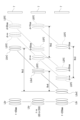
- FIG. 1 is a diagram illustrating a configuration example of an imaging device according to a first embodiment of the present technology.
- FIG. 2 is a diagram illustrating an example of the configuration of an optical system.
- FIG. 2 is a schematic diagram showing an optical system and its driving mechanism.
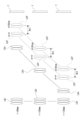
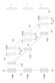
- 5A and 5B are diagrams illustrating movable ranges of lens groups in zoom tracking control as a first control.
- FIG. 11 is a diagram showing a movable range of a lens group in macro photography control as a second control.
- FIG. 2 is a diagram illustrating a functional configuration of a control unit.
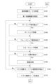
- 10 is a flowchart illustrating an example of a process executed by a control unit.
- 8 is a flowchart showing an example of a process executed by the control unit following FIG. 7 .
- FIG. 10 is a flowchart illustrating an example of a process executed by a control unit following FIG. 7 .
- FIG. 13 is a diagram showing an example of a shooting screen in a normal shooting mode.
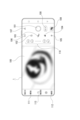
- FIG. 4 is a diagram showing an example of a shooting screen in a macro shooting mode.
- FIG. 13 is a diagram showing a second example of a shooting screen in normal shooting mode.
- FIG. 13 is a diagram showing a third example of a shooting screen in normal shooting mode.
- FIG. 13 is a diagram showing a fourth example of the shooting screen in normal shooting mode.
- FIG. 13 is a diagram showing a fifth example of a shooting screen in normal shooting mode.
- 11A and 11B are diagrams for explaining an example in which mode switching is performed by changing the focal length.
- FIG. 1 is a diagram showing an example of the configuration of an imaging apparatus that switches modes depending on the distance to a subject.
- FIGS. 13A and 13B are diagrams illustrating a movable range of a lens group in a first control according to the second embodiment.
- FIG. 13 is a diagram illustrating a movable range of a lens group in a second control according to the second embodiment.
- 13A and 13B are diagrams illustrating the movable range of a lens group in a first control and a second control in the third embodiment.
- 13 is a flowchart showing an example of a process executed by a control unit following that shown in FIG. 7 in the third embodiment;
- FIG. 11 is a diagram for explaining a second control range in the modified example.
- an imaging device 1 An example of the configuration of an imaging device 1 according to a first embodiment will be described with reference to Fig. 1. Note that the imaging device 1 in this example is an information processing device equipped with a camera function, and in the following description, a smartphone will be taken as an example.
- the imaging device 1 which is a smartphone, includes a camera module 2, a control unit 3, a display module 4, and a memory unit 5.
- the camera module 2 includes an optical system 6, a pixel array section 7, a driver section 8, a readout section 9, an AD (Analog to Digital) conversion section 10, a signal processing section 11, and a camera control section 12.
- an optical system 6 a pixel array section 7, a driver section 8, a readout section 9, an AD (Analog to Digital) conversion section 10, a signal processing section 11, and a camera control section 12.
- AD Analog to Digital
- the optical system 6 is made up of optical components such as various lenses and an aperture mechanism for collecting incident light onto the pixel array unit 7.
- the optical system 6 may include a mechanical shutter mechanism.
- the optical system 6 of this embodiment includes a prism mirror PM and three lens groups LG.
- the three lens groups LG are a fixed relay group LGr, a movable variator group LGv, and a movable focus group LGf.
- the pixel array unit 7 is provided in, for example, a charge coupled device (CCD) type or complementary metal oxide semiconductor (CMOS) type image sensor, and is configured by two-dimensionally arranging pixels having photoelectric conversion elements. Each pixel is configured by laminating, for example, a microlens, a light receiving element, a filter, etc., and outputs an electrical signal obtained by photoelectrically converting received light by the light receiving element.
- CCD charge coupled device
- CMOS complementary metal oxide semiconductor
- the pixel array section 7 in this embodiment has color pixels such as R (red) pixels, G (green) pixels, and B (blue) pixels.
- the driver unit 8 includes a motor driver that drives the above-mentioned lens groups LG, the aperture mechanism, and the prism mirror PM based on control signals output from the camera control unit 12 .
- Each motor driver supplies a drive current according to an instruction from the camera control unit 12 to the corresponding drive motor.
- the driver unit 8 acquires position information for each lens group LG based on detection signals from hall sensors (not shown).
- the driver unit 8 continuously controls the position of the optical system 6 by performing feedback control based on the position information for each lens group LG.
- the readout unit 9 reads out the electric charge accumulated in each pixel of the pixel array unit 7 in accordance with various timing signals. This readout process is performed, for example, for each row selected sequentially in the pixel array unit 7.
- the AD conversion unit 10 performs AD conversion processing to convert the charge (pixel signal of analog data) read by the readout unit 9 into a digital value.
- the signal processing unit 11 performs various processes on the pixel signals as digital data output from the AD conversion unit 10 to generate image data. Specifically, the signal processing unit 11 performs pre-processing and post-processing.
- Pre-processing may include, for example, pixel rearrangement processing based on various correction processes, brightness adjustment processing, white balance adjustment processing, HDR (High Dynamic Range) processing, and noise reduction processing.
- Post-processing can include, for example, color correction.
- the signal processing unit 11 also performs resolution conversion processing to convert a high-resolution image into a low-resolution image. For example, the signal processing unit 11 performs processing to convert an image with a resolution according to the number of pixels, such as a 2K image of about 1920 pixels vertically and 1080 pixels horizontally, a 4K image of about 4096 pixels vertically and 2160 pixels horizontally or about 3840 pixels vertically and 2160 pixels horizontally, or an 8K image of about 7680 pixels vertically and 4320 pixels horizontally, into an image with a lower resolution.
- a 2K image of about 1920 pixels vertically and 1080 pixels horizontally such as a 2K image of about 1920 pixels vertically and 1080 pixels horizontally, a 4K image of about 4096 pixels vertically and 2160 pixels horizontally or about 3840 pixels vertically and 2160 pixels horizontally, or an 8K image of about 7680 pixels vertically and 4320 pixels horizontally, into an image with a lower resolution.
- the camera control unit 12 executes at least two controls, a first control C1 and a second control C2, by controlling the optical system 6 via the driver unit 8.
- the first control C1 is a zoom tracking control that performs zooming without changing the focal distance d.
- the focal distance d refers to the distance to a subject in a focused state.
- the first control C1 enables zoom tracking control by limiting the movable range of the focus group LGf according to the position of the variator group LGv, while also performing collision avoidance control for each lens group LG.
- the second control C2 individually controls the variator group LGv and the focus group LGf, which are the movable lens groups LG. At this time, no control is performed to avoid collisions between the lens groups LG, so in the second control C2, when issuing an instruction to the camera control unit 12 to drive the lens groups LG, it is necessary to issue an instruction to prevent collisions between the lens groups LG.
- the second control C2 is used in macro photography control to perform macro photography optimally.
- the movable range of the focus group LGf is not limited according to the position of the variator group LGv, it is possible to execute control to shorten the focal distance d.
- the camera control unit 12 switches between the first control C1 and the second control C2 based on an instruction from the control unit 3.
- the camera control unit 12 may be capable of executing a control different from the first control C1 or the second control C2, or a control (e.g., autofocus control) that is performed simultaneously with the first control C1 or the second control C2.
- the control unit 3 performs overall control of the imaging device 1 as a smartphone.
- the control unit 3 includes a CPU (Central Processing Unit) 13, a GPU (Graphics Processing Unit) 14, a ROM (Read Only Memory) 15, and a RAM (Random Access Memory) 16.
- CPU Central Processing Unit
- GPU Graphics Processing Unit
- ROM Read Only Memory
- RAM Random Access Memory
- the CPU 13, GPU 14, ROM 15, and RAM 16 are interconnected by a bus 17.
- the CPU 13 executes processes related to various applications executed by the information processing device as a smartphone. In other words, the CPU 13 executes processes to realize not only functions realized using the camera module 2, but also functions unrelated to the camera module 2, such as e-mail and telephone.
- the CPU 13 performs further processing on the processed images generated by the signal processing unit 11 to generate still image data and moving image data to be stored in the storage unit 5.
- the CPU 13 performs zooming and focusing by controlling the optical system 6 via the camera control unit 12. These zooming and focusing operations may be performed manually by the user or automatically.
- the CPU 13 uses the first control C1 and the second control C2 provided by the camera module 2 to instruct the driving of the lens group LG.
- both the variator group LGv and the focus group LGf are driven using the first control C1 provided by the camera module 2.
- the second control C2 provided by the camera module 2 is used to drive the focus group LGf over a wider range.
- normal shooting mode M1 is given as an example of a mode that uses the first control C1.
- Macro shooting mode M2 is given as an example of a mode that uses the second control C2.
- the second control C2 can be used in a calibration mode, etc.
- the CPU 13 switches between normal shooting mode M1 and macro shooting mode M2.
- the GPU 14 is a computational processing unit that performs image processing, for example, processing to display still images and moving images on the display module 4.
- the ROM 15 and RAM 16 store programs and the like used by the control unit 3.
- the ROM 15 and RAM 16 store an operating system (OS) and content files such as image files that the CPU 13 and GPU 14 use to control each unit, as well as application programs and firmware for various operations.
- OS operating system
- content files such as image files that the CPU 13 and GPU 14 use to control each unit, as well as application programs and firmware for various operations.
- the ROM 15 and RAM 16 used by the CPU 13 and the ROM 15 and RAM 16 used by the GPU 14 may each be provided in the control unit 3.
- control unit 3 realized by the CPU 13 and GPU 14 will be described later.
- the display module 4 performs processing to display images such as still images and moving images based on control signals from the control unit 3.
- the display module 4 includes a display unit 18, a VRAM (Video RAM) 19, and an operation unit 20.
- VRAM Video RAM
- the display unit 18 is, for example, a display device such as a liquid crystal display (LCD) or an organic electro-luminescence (EL) display.
- the display unit 18 may be provided as an EVF (Electric Viewfinder) or the like.
- the display unit 18 displays still images and video images captured and stored by the photographer.
- the images displayed on the display unit 18 include not only through images displayed during standby for the release operation, but also still image data and video data stored in the memory unit 5.
- VRAM 19 is a storage unit that temporarily stores data for the display image displayed on display unit 18.
- the display device provided as the display unit 18 functions as the operation unit 20 by being equipped with a touch panel function.
- the CPU 13 receives a detection signal detected in response to an operation on the operation unit 20, and executes various processes in response to the content of the operation. For example, the CPU 13 receives a detection signal corresponding to a menu operation and performs processing corresponding to the selected menu item. For example, when a switching operation between the normal shooting mode M1 and the macro shooting mode M2 is detected, the CPU 13 performs a display process for informing the user of the switched mode and a process for switching the control of the optical system 6 for the camera control unit 12.
- the CPU 13 receives a detection signal corresponding to a pinch-in operation or a pinch-out operation on the operation unit 20, and supplies an instruction to the camera control unit 12 to perform a specified zooming operation.
- the CPU 13 receives a detection signal corresponding to the operation of tapping on a subject displayed on the display unit 18 from the operation unit 20, and supplies instructions to the camera control unit 12 for processing to identify the subject that is the target of the tap operation and for focusing to bring the identified subject into focus.
- Camera module configuration A mechanism for driving the optical system 6 included in the camera module 2 will be described with reference to FIGS.
- FIG. 2 is a side view that diagrammatically illustrates a portion of the optical system 6 included in the camera module 2, showing the prism mirror PM, the relay group LGr, the variator group LGv, and the focus group LGf.
- the lenses of the relay group LGr, the variator group LGv, and the focus group LGf are shown as convex lenses for the sake of convenience, but this is for the sake of convenience, and some of the lenses of the relay group LGr, the variator group LGv, and the focus group LGf may be other lenses such as concave lenses.
- Figure 3 is a cross-sectional view that shows a schematic of the optical system 6 and its driving mechanism.
- the camera module 2 includes a relay group LGr, a variator group LGv, a focus group LGf, a relay holding unit 31 that holds the relay group LGr, a variator drive unit 32 that drives the variator group LGv, and a focus drive unit 33 that drives the focus group LGf.
- the relay holding unit 31 is provided with a holding unit 34 that holds the relay group LGr.
- the variator drive unit 32 includes a slide unit 35 that moves relative to the relay holding unit 31 while the variator group LGv is held therein, a magnet 36 attached to the slide unit 35, a coil 37 arranged opposite the magnet 36, a flexible cable 38 provided on the side of the relay holding unit 31 and having a circuit that supplies current to the coil 37, and a magnetic yoke 39 provided on the outside of the flexible cable 38.
- the variator driving section 32 is provided with a holding section 40 that holds the variator group LGv.
- Two balls 41 are attached to the variator drive section 32 so as to be rotatable, and are spaced apart in the optical axis direction.
- a groove 42 is formed on the inner surface of the relay holding portion 31 at a position opposite the ball 41 and extending in the optical axis direction.
- the variator drive unit 32 moves smoothly in the optical axis direction relative to the relay holding unit 31.
- the movement of the variator driving unit 32 in the optical axis direction relative to the relay holding unit 31 is achieved by passing a current through the coil 37.
- a force acts to make the N pole of the magnet 36 face the coil 37. This force causes the variator driving portion 32 to move in one direction along the optical axis relative to the relay holding portion 31 .
- the focus drive unit 33 includes a slide unit 43 that moves relative to the relay holding unit 31 while holding the focus group LGf, a magnet 44 attached to the slide unit 43, a coil 45 arranged opposite the magnet 44, a flexible cable 46 provided on the side of the relay holding unit 31 and having a circuit that supplies current to the coil 45, and a magnetic yoke 47 provided on the outside of the flexible cable 46.
- the focus driving section 33 is provided with a holder 48 that holds the focus group LGf.
- Two balls 49 are attached to the focus drive unit 33 so as to be rotatable and spaced apart in the optical axis direction.
- a groove 50 is formed on the inner circumferential surface of the relay holding portion 31 at a position corresponding to the ball 49 and extending in the optical axis direction.
- the focus driver 33 drives the relay holder 31 in the optical axis direction by passing a current through the coil 45.
- the focus driver 33 is driven in the same manner as the variator driver 32, so a description of the drive is omitted.
- the ball 41 is provided on the slide portion 35 and the groove portion 42 is formed on the relay holding portion 31, but the ball 41 may be provided on the relay holding portion 31 and the groove portion 42 may be formed on the slide portion 35.
- a ball 49 may be provided on the relay holding portion 31, and a groove portion 50 may be formed on the slide portion 43.
- the movable range of the variator group LGv and the movable range of the focus group LGf are partially overlapped.
- the camera module 2 also includes a thermistor for controlling temperature characteristics.
- the thermistor is provided, for example, in the flexible cables 38, 46.
- the driver unit 8 estimates the temperature of each lens group LG based on temperature information obtained from the thermistor, and corrects the position of the lens group LG.
- FIG. 4 shows the movable range of each lens group LG in the zoom tracking control as the first control C1.
- the variator group LGv which is a movable lens group LG, is a lens group LG with negative refractive power, and the focal length f is increased as it moves away from the pixel array unit 7 and closer to the relay group LGr. That is, the variator group LGv is closest to the pixel array unit 7 at the wide-angle end and closest to the relay group LGr at the telephoto end.
- the focus group LGf which is a movable lens group LG, is a lens group LG having negative refractive power, and is closer to the pixel array unit 7 as the focal distance d becomes shorter, and is closer to the variator group LGv as the focal distance d becomes longer. Further, the movable range of the focus group LGf is a predetermined range according to the position of the variator group LGv, and changes depending on the position of the variator group LGv.
- the range within which the focus group LGf can physically move is referred to as the "physical range of movement.”
- the range within which the focus group LGf can move when the relay group LGr does not exist is the physical range of movement.
- the physical range of movement is determined, for example, by the mechanical end.
- the range in which the focus group LGf can be moved by control that takes into account temperature characteristics, etc., is referred to as a “physical control range.”
- the physical control range is a range in which various margins, such as drift margins, are provided at both ends of the physical movement range.
- the physical control range of the focus group LGf is set so as to partially overlap with the physical control range of the variator group LGv.
- the movable range of the focus group LGf which is determined according to the position of the variator group LGv, is referred to as the "first control range Rn1.”
- the first control range Rn1 is a further part of the physical control range, and changes according to the position of the variator group LGv.
- the focal length f is 125 mm
- the variator group LGv is moved to the wide end with the focal distance d set closer than 50 cm, the position of the focus group LGf will be outside the physical control range, and it will no longer be possible to maintain focus on the currently focused subject, i.e., zoom tracking control will no longer be able to be performed normally.
- the first control range Rn1 is set to be significantly narrower than the physical control range.
- FIG. 5 shows the movable range of each lens group LG in macro photography control as the second control C2.
- macro photography control not only the relay group LGr but also the variator group LGv is fixed.
- the variator group LGv is fixed to a position (telephoto end) when the focal length f is 125 mm.
- the movable range of the focus group LGf is set to be as wide as the physical control range.
- the movable range of the focus group LGf in the second control C2 is set to a "second control range Rn2.”
- the closest limit value of the second control range Rn2 is set to, for example, approximately the same position as the closest limit value (focus distance d is 50 cm) of the first control range Rn1 at the wide end of the first control C1.
- the limit value on the infinity side of the second control range Rn2 is set to, for example, approximately the same position as the limit value on the infinity side of the first control range Rn1 at the telephoto end of the first control C1.
- the focal distance d is measured while moving the positions of the variator group LGv and the focus group LGf for each camera module 2, and a process is performed in advance to calculate a table or formula that represents a tracking curve based on the measurement results.
- the focus distance d measured under six conditions is used, which are a combination of three conditions in which the position of the variator group LGv is different (wide end, telephoto end, and intermediate) and two conditions in which the position of the focus group LGf is different (infinity position and the closest position such as 50 cm).
- three conditions in which the position of the variator group LGv is different wide end, telephoto end, and intermediate
- two conditions in which the position of the focus group LGf is different infinity position and the closest position such as 50 cm.
- Fig. 6 Functions realized by the control unit 3 executing a program are shown in Fig. 6. Note that the functions shown in Fig. 6 are functions realized while the camera application is running, and the control unit 3 can appropriately realize functions according to other applications. In addition, there are some functions that are realized while the camera application is running, such as an image processing function for an image obtained by capturing an image, but are not shown in Fig. 6.
- the control unit 3 has an operation detection function F1, a mode switching function F2, a zooming function F3, a focusing function F4, and a release function F5.
- the operation detection function F1 detects user operations related to the camera application, determines the type of user operation, and executes other functions according to the determination result.
- the mode switching function F2, zooming function F3, focusing function F4, and release function F5 are examples of functions executed based on the detection result of the operation detection function F1.
- the mode switching function F2 switches between the normal shooting mode M1 and the macro shooting mode M2 described above. These mode switching operations are not only performed in response to user operations, but may also be performed in response to changes in the distance to the subject, as described below.
- the zooming function F3 moves the variator group LGv in response to the user's zooming operation. This function is realized by the control unit 3 supplying instructions to the camera control unit 12 of the camera module 2.
- the focusing function F4 moves the focus group LGf in response to a focusing operation by the user. This function is realized by the control unit 3 supplying an instruction to the camera control unit 12 of the camera module 2. It should be noted that while the tracking autofocus function is active, the focusing function F4 is automatically executed in response to the movement of the subject in the optical axis direction.
- the release function F5 realizes an image capturing operation by supplying exposure and readout instructions to the pixel array unit 7 in response to a release operation by the user.
- the release function F5 may be configured to be automatically executed when a predetermined condition is met, such as when a smiling face of a subject is detected.
- Processing flow 7 and 8 show an example of processing executed by the control unit 3 of the imaging device 1. Note that connections between processes in the drawings are represented by connectors Cn1 and Cn2.
- control unit 3 starts the series of processes shown in Figs. 7 and 8.
- step S101 the control unit 3 sets the normal shooting mode M1.
- an icon or the like indicating that the imaging device 1 is running in the normal shooting mode M1 is displayed on the display unit 18 of the display module 4 of the imaging device 1.
- step S102 the control unit 3 sets the first control range Rn1 as the control range of the focus group LGf. This allows the control unit 3 to drive each lens group LG while avoiding collisions between the lens groups LG.
- step S103 the control unit 3 determines whether or not a zooming operation has been detected.
- a zooming operation is, for example, a pinch-in operation or a pinch-out operation performed on the display unit 18. It is also a slide operation on a slider operator that can select the zoom magnification.
- step S104 the control unit 3 performs zooming processing in step S104.
- the zooming processing the variator group LGv is moved.
- the amount of movement of the variator group LGv at this time corresponds to the amount of zooming operation, etc.
- control unit 3 when the variator group LGv is moved in response to a zooming operation, the control unit 3 simultaneously moves the focus group LGf as a zoom tracking control. This prevents the focus state of the subject being focused from changing.
- control unit 3 avoids the processing of step S104.
- step S105 the control unit 3 determines whether or not a focusing operation has been detected.
- a focusing operation is, for example, an operation of tapping on a subject on a through image displayed on the display unit 18, or a sliding operation on a slider control for changing the focal distance d.
- the control unit 3 performs a focusing process in step S106.
- the focus group LGf is moved.
- the amount of movement of the focus group LGf at this time corresponds to the amount of focusing operation, etc.
- the focus group LGf is positioned at the end of that range and is not moved any further.
- control unit 3 avoids the processing of step S106.
- step S107 the control unit 3 determines whether or not a release operation has been detected. If it is determined that a release operation has been detected, the control unit 3 executes image capture processing in step S108.
- control unit 3 avoids the processing of step S108.
- step S109 the control unit 3 determines whether or not a transition operation to the macro shooting mode M2 has been detected.
- a transition operation to the macro shooting mode M2 is, for example, an operation of tapping a button for transitioning to the macro shooting mode M2.
- an operation of moving the imaging device 1 closer to the subject may be regarded as the transition operation.
- control unit 3 If it is determined that the transition operation to the macro shooting mode M2 has not been detected, the control unit 3 returns to step S103 again. That is, in the normal shooting mode M1, the control unit 3 sequentially executes each determination process of steps S103, S105, S107, and S109, and executes the corresponding process when the determination is Yes.
- control unit 3 sets the macro photography mode M2 in step S110. As a result, an icon or the like indicating that the imaging device 1 is running in the macro photography mode M2 is displayed on the display unit 18 of the imaging device 1.
- step S111 of FIG. 8 the control unit 3 sets the second control range Rn2 as the control range of the focus group LGf. This allows the control unit 3 to move the focus group LGf over a wide range during macro photography.
- step S112 the control unit 3 moves the variator group LGv to a predetermined position.
- the predetermined position is, for example, the infinity end (telephoto end) of the physical control range of the variator group LGv.
- the focus group LGf may be moved so as not to change the subject to be focused on. That is, the focus group LGf may be moved by zoom tracking control.
- step S113 the control unit 3 determines whether or not a focusing operation has been detected. If it is determined that a focusing operation has been detected, then in step S114, the control unit 3 moves the focus group LGf by executing a focusing process.
- step S115 the control unit 3 determines whether or not a release operation has been detected. If it is determined that a release operation has been detected, the control unit 3 performs imaging processing in step S116.
- step S117 the control unit 3 determines whether or not a transition operation to the normal shooting mode M1 has been detected.
- a transition operation to the normal shooting mode M1 is, for example, an operation of tapping a button for transitioning to the normal shooting mode M1.
- an operation of moving the imaging device 1 away from the subject may be regarded as the transition operation.
- control unit 3 When it is determined that an operation for transitioning to the normal shooting mode M1 has been detected, the control unit 3 returns to step S101 in FIG. On the other hand, when it is determined that the operation for transitioning to the normal shooting mode M1 has not been detected, the control unit 3 returns to step S113.
- control unit 7 and 8 are examples of processes executed by the control unit 3.
- the control unit 3 can execute various processes not shown in FIG. 7 or 8 in response to user operations, etc.
- the control unit 3 performs processes such as displaying a menu screen on the display unit 18 in response to a menu operation performed by the user, and reading an image file stored in the memory unit 5 and displaying it on the display unit 18 in response to a user performing an operation to select an image that has already been captured.
- the first example is one in which an operator is provided on the display section 18 of the display module 4 to switch to macro photography mode M2.
- the shooting screen for normal shooting mode M1 and other modes other than macro shooting mode M2 includes a through image display area 100, a shooting button 101, a flash setting button 102, a continuous shooting button 103, a blur adjustment button 104, a brightness adjustment button 105, an image size change button 106, a camera switching button 107, a still image/video switching button 108, a thumbnail area 109, a zooming operation area 110, a menu button 111, and an additional function button 112.
- the shooting screen is provided with a macro shooting button 113.
- the shooting screen in macro shooting mode M2 is displayed on the display unit 18 as shown in FIG. 10.
- the shooting screen in macro shooting mode M2 includes a mode display area 114 superimposed on the through image display area 100, a focus distance change operation area 115, a shooting button 101, a still image/video switching button 108, a thumbnail area 109, a menu button 111, an additional function button 112, and a back button 116.
- the mode display area 114 displays a message indicating that the current mode is macro photography mode M2.
- the focus distance change operation area 115 includes a slider operator 115a for moving the focus group LGf, and multiple focus buttons 115b for moving the focus group LGf to a predetermined position.
- the focus buttons 115b include a button for moving the focus group LGf to infinity, a button for moving it to the closest position, and the like.
- the mode transitions to the mode before the transition to the macro shooting mode M2 (for example, the normal shooting mode M1), and the display on the display unit 18 also switches to the screen before the transition to the macro shooting mode M2 (see Figure 9).
- the macro shooting mode M2 for example, the normal shooting mode M1
- the display on the display unit 18 also switches to the screen before the transition to the macro shooting mode M2 (see Figure 9).
- a macro shooting button 113 may be provided next to a zooming operation area 110. According to the aspect shown in Fig. 11, the user can imagine performing macro shooting as an extension of the zooming operation.
- a flash setting button 102 a continuous shooting button 103, a blur adjustment button 104, a brightness adjustment button 105, and a macro shooting button 113 may be provided.
- a macro shooting button 113 may be included among the buttons displayed in a shooting mode selection field 117 for selecting a shooting mode.
- the macro shooting button 113 may also be included in the additional function area 118 (see FIG. 14) that is displayed when the additional function button 112 shown in FIG. 10 etc. is pressed.
- icon image of the macro shooting button 113 shown in each figure is just an example, and other icon images may be used.
- the second example of mode switching is when the camera automatically switches from normal shooting mode M1 to macro shooting mode M2 by performing a zooming operation.
- Figure 15 shows the process of changing the focal length f from 120 mm to 125 mm by moving the variator group LGv to the telephoto end.
- the focus group LGf In response to the change in focal length f from 120 mm to 125 mm, the focus group LGf is moved toward the telephoto side by the zoom tracking control. In addition, as the focus group LGf moves toward the telephoto side, the movable range of the focus group LGf switches from the first control range Rn1 to the second control range Rn2. In addition, at the same time that the movable range switches from the first control range Rn1 to the second control range Rn2, the zoom tracking control is set to off.
- the camera smoothly transitions to macro photography mode M2 simply by moving the variator group LGv to the telephoto end, reducing the operational burden on the user.
- the third example of mode switching is one in which the mode is changed appropriately depending on the distance to the subject.
- the configuration of an image pickup apparatus 1A in this example is shown in FIG.
- the imaging device 1A includes a camera module 2, a control unit 3, a display module 4, a storage unit 5, and a distance measurement module 61.
- the configurations of the camera module 2, control unit 3, display module 4, and storage unit 5 are the same as those of the imaging device 1, so a description thereof will be omitted.
- the distance measurement module 61 is a module that performs distance measurement using, for example, the iToF (indirect ToF) method, and includes a light emitting unit 62, a distance measurement control unit 63, a ToF sensor 64, a readout unit 65, an AD conversion unit 66, and a signal processing unit 67.
- the iToF method calculates the distance from the imaging device 1A to the subject by detecting the difference between the phase of intensity-modulated illumination light irradiated onto the subject and the phase of reflected light reflected by the subject.
- the light-emitting unit 62 is configured with a light source capable of emitting infrared light, and emits infrared light by supplying an emission signal generated based on a clock signal supplied from the distance measurement control unit 63 to the light source.
- the ToF sensor 64 receives infrared light reflected from the subject and distributes the electric charge obtained by photoelectric conversion to two charge storage sections.
- the readout unit 65 reads out a signal corresponding to the amount of charge stored from the two charge storage units in each pixel.
- the AD conversion unit 66 performs AD conversion processing to convert the analog signal read by the reading unit 65 into a digital value.
- the signal processing unit 67 calculates distance information for each pixel based on the pixel signal as digital data output from the AD conversion unit 66.
- This distance information for each pixel is, for example, a distance image.
- the distance information for each pixel calculated by the signal processing unit 67 is output to the control unit 3.
- the control unit 3 calculates distance information for each subject based on the distance information for each pixel output from the distance measurement module 61.
- the control unit 3 automatically switches from normal shooting mode M1 to macro shooting mode M2 when the distance to the subject to be focused is less than a predetermined distance, for example, less than 50 cm.
- step S109 in FIG. 7 instead of detecting an operation to transition to macro shooting mode M2, the control unit 3 determines whether the distance to the subject to be focused is less than a predetermined distance. Then, if it is determined that the distance to the subject is less than the predetermined distance, the control unit 3 proceeds to step S109.
- Second embodiment An imaging device 1B according to the second embodiment will be described.
- the configuration of a variator group LGvB is different from that in the first embodiment.
- the variator group LGvB is a lens group LG with positive refractive power.
- the relay group LGr in the imaging device 1B is a fixed lens group LG
- the focus group LGf is a lens group LG with negative refractive power.
- each lens group LG in the zoom tracking control as the first control C1 is shown in FIG. 17.
- the focal length f of the variator group LGvB is shortened as it moves away from the pixel array unit 7 and closer to the relay group LGr. That is, the variator group LGvB is closest to the relay group LGr at the wide-angle end and closest to the pixel array unit 7 at the telephoto end.
- the focus group LGf moves in the same direction as the variator group LGvB.
- the shorter the focal distance d the closer it is to the pixel array section 7, and the longer the focal distance d, the closer it is to the variator group LGvB.
- FIG. 18 shows the movable range of each lens group LG in macro shooting mode M2 in the second embodiment.
- macro shooting control not only the relay group LGr but also the variator group LGvB is fixed.
- the variator group LGvB is fixed to a position when the focal length f is 85 mm, i.e., the wide end.
- the second control range Rn2 of the focus group LGf is determined based on the closest limit value of the first control range Rn1 at the telephoto end of the first control C1 and the infinity limit value of the first control range Rn1 at the wide-angle end of the first control C1.
- the control unit 3 uses the closest limit value of the first control range Rn1 at the telephoto end of the first control C1 and the infinity limit value of the first control range Rn1 at the wide-angle end of the first control C1.
- step S112 of FIG. 8 the control unit 3 moves the variator group LGvB to a predetermined position.
- the predetermined position is, for example, the wide-angle end position.
- the imaging device 1C in the third embodiment is an example in which zoom tracking control is performed even in the macro shooting mode M2.
- the zoom tracking control in the normal shooting mode M1 is referred to as "first zoom tracking control”
- the zoom tracking control in the macro shooting mode M2 is referred to as "second zoom tracking control.” That is, the control unit 3 in the third embodiment performs a first zoom tracking control as the first control C1, and performs a second zoom tracking control as the second control C2.
- the longest focal length f was set to 125 mm, making it possible to perform suitable macro photography at the telephoto end. Therefore, in the imaging device 1 of the first embodiment, the variator group LGv is fixed at the telephoto end, and the focus group LGfC is moved to perform photography in macro photography mode M2.
- the longest focal length f of the imaging device 1C is set to 200 mm, if the variator group LGv is fixed to the telephoto end, the angle of view becomes too narrow, and it may not be suitable for shooting in macro shooting mode M2.
- the position of the variator group LGvC in the macro shooting mode M2 is not fixed to the telephoto end but is movable. Then, in the imaging device 1C, the focus group LGfC is moved in conjunction with the movement of the variator group LGvC, thereby performing a second zoom tracking control.
- the movable range of the variator group LGvC in the imaging device 1C in the normal imaging mode M1 is defined as a third control range Rn3 (see FIG. 19).
- the movable range of the variator group LGvC in the image pickup apparatus 1C in the macro photography mode M2 is defined as a fourth control range Rn4, which is narrower than the third control range Rn3.
- the limit value on the infinity side of the fourth control range Rn4 is the position when the focal length f is 200 mm, i.e., the telephoto end position.
- the limit value on the closest side of the fourth control range Rn4 is the position when the focal length f is an integer n.
- the integer n is a value longer than 85 mm and shorter than 200 mm.
- the focal length f can be changed from an integer n to 200 mm.
- the focus group LGfC is closest to the pixel array section 7 when the focal length f is an integer n and the focal distance d is the shortest.
- the focus group LGfC is closest to the relay group LGr when the focal length f is set to the longest, 200 mm, and the focus distance d is set to the longest.
- the second control range Rn2 is part of the physical control range of the focus group LGfC and changes depending on the position of the variator group LGvC (see FIG. 19).
- FIG. 7 An example of the processing executed by the control unit 3 in the third embodiment is shown in Figs. 7 and 20. Note that in Fig. 20, the same processes as those in Fig. 8 are given the same step numbers, and the explanation is omitted as appropriate. The connections between the processes in the drawings are indicated by connectors Cn1 and Cn2.
- control unit 3 starts the series of processes shown in Figs. 7 and 20.
- the control unit 3 sets the normal shooting mode M1 in step S101, and sets the first control range Rn1 as the control range of the focus group LGfC in step S102.
- the control unit 3 performs the determination processes of steps S103, S105, and S107, and if the determination is Yes, executes the appropriate corresponding process (the process of steps S106, S108, and S110).
- step S109 the control unit 3 determines whether or not an operation to transition to the macro shooting mode M2 has been detected. If it is determined that an operation to transition to the macro shooting mode M2 has not been detected, the control unit 3 returns to step S103 again.
- control unit 3 sets the macro photography mode M2 in step S110.
- the control unit 3 drives the variator group LGvC into the fourth control range Rn4 in step S132.
- the variator group LGvC is moved, for example, to the closest side in the fourth control range Rn4.
- step S133 the control unit 3 determines whether or not a zooming operation has been detected.
- the control unit 3 performs a zooming process in step S134.
- the zooming process the variator group LGv is moved.
- the amount of movement of the variator group LGvC at this time corresponds to the amount of zooming operation, etc.
- the control unit 3 simultaneously moves the focus group LGfC as a second zoom tracking control. This prevents the focus state of the subject being focused from changing.
- control unit 3 performs the determination processes of steps S113 and S115, and if the determination is Yes, executes the appropriate corresponding process (steps S114 and S116).
- step S117 the control unit 3 determines whether or not an operation to transition to the normal shooting mode M1 has been detected. If it is determined that an operation to transition to the normal shooting mode M1 has been detected, the control unit 3 returns to step S101 in FIG. On the other hand, when it is determined that the operation for transitioning to the normal shooting mode M1 has not been detected, the control unit 3 returns to step S133.
- the position on the infinity side of the focus group LGf may be set to a short focal distance d, such as 1 m or 50 cm, instead of infinity (see FIG. 21).
- d a short focal distance
- the focus distance d since the intention is clearly to shoot a subject located at a close distance, there is no need to set the focus distance d to infinity. This makes it possible to reduce the focusing time when performing autofocus control, etc.
- the imaging device 1 (1A, 1B, 1C) in the present technology is equipped with a control unit 3 that switches between a first control C1 that moves a second lens group (focus group LGf, LGfC) consisting of one or more lenses within a first control range Rn1 that corresponds to the position in the optical axis direction of a first lens group (variator group LGv, LGvB, LGvC) consisting of one or more lenses, and a second control C2 that moves the second lens group (focus group LGf) within a second control range Rn2 that is wider than the first control range Rn1, in accordance with predetermined conditions.
- a control unit 3 that switches between a first control C1 that moves a second lens group (focus group LGf, LGfC) consisting of one or more lenses within a first control range Rn1 that corresponds to the position in the optical axis direction of a first lens group (variator group LGv, LGvB, LGvC) consisting of one or more lenses, and a second control C2
- the second lens group (focus group LGf) can be moved within a first control range Rn1 determined according to the position of the first lens group (variator group LGv) in the optical axis direction.
- the first control range Rn1 at this time is determined, for example, so that zoom tracking control that maintains the subject to be focused when the position of the first lens group (variator group LGv) is moved is possible. That is, the first control range Rn1 in a state in which the first lens group (variator group LGv) is fixed is set to a relatively narrow range.
- the second control range Rn2 is wider than the first control range Rn1, and is capable of focusing on a closer subject, for example.
- the first lens group in the imaging device 1 (1A, 1B, 1C) may be a variator group LGv (LGvB, LGvC), and the second lens group may be a focus group LGf (LGfC).
- LGvB, LGvC variator group LGv
- LGfC focus group LGf
- the specified condition for switching from the first control C1 to the second control C2 may be a condition that the variator group LGv (LGvB, LGvC) is located at a specified position. Since the first control C1 can be switched to the second control C2 by positioning the variator group LGv at a predetermined position, no button operation or menu operation is required for mode switching, which enables smooth mode switching and smooth shooting, thereby improving usability.
- the variator group LGv (LGvC) in the imaging device 1 (1A, 1C) may be a lens group LG having negative refractive power
- the focus group LGf (LGfC) may be a lens group LG having negative refractive power.
- the control unit 3 may calculate (set) the closest limit value in the second control range Rn2 according to the closest limit value in the first control range Rn1 at the wide end in the first control C1. According to this configuration, both the variator group LGv and the focus group LGf approach the subject side at the wide-angle end, and approach the pixel array unit 7 at the telephoto end.
- the limit value on the closest side of the second control range Rn2 of the focus group LGf is determined according to the position where the focus group LGf is closest to the pixel array unit 7 in the first control C1. That is, the second control range Rn2 can be set wide, and the focusable range can be widened.
- the control unit 3 in the imaging device 1 (1A, 1B, 1C) may fix the variator group LGv (LGvB, LGvC) to a predetermined position in the second control C2. This makes it possible to simplify the control for avoiding a collision between the variator group LGv and the focus group LGf (LGfC), thereby reducing the cost associated with generating algorithms and the control burden on the imaging device 1.
- the control unit 3 in the imaging device 1 (1A) may fix the variator group LGv to the telephoto end in the second control C2, and calculate (set) the limit value on the infinity side of the second control range Rn2 in accordance with the limit value on the infinity side of the first control range Rn1 at the telephoto end.
- the variator group LGv is positioned closer to the subject side than the focus group LGf, it is possible to move the limit value on the infinity side of the focus group LGf closer to the subject side. Therefore, it becomes possible to set the second control range Rn2 wider, and the focusable range can be expanded.
- the physical control range in the optical axis direction of the first lens group (variator group LGv, LGvB, LGvC) and the physical movement range in the optical axis direction of the second lens group (focus group LGf, LGfC) may be at least partially overlapping.
- the first lens group (variator group LGv) and the second lens group (focus group LGf) by fixing the position of the first lens group (variator group LGv), it is possible to simplify control of the second lens group (focus group LGf) while avoiding collision.
- the variator group LGvB in the image pickup device 1B may be a lens group LG having positive refractive power
- the focus group LGf may be a lens group LG having negative refractive power.
- the control unit 3 may calculate (set) the closest limit value in the second control range Rn2 according to the closest limit value in the first control range Rn1 at the telephoto end in the first control C1. According to this configuration, both the variator group LGvB and the focus group LGf approach the pixel array unit 7 at the wide-angle end, and approach the subject side at the telephoto end.
- the limit value on the closest side of the second control range Rn2 of the focus group LGf is determined according to the position where the focus group LGf is closest to the pixel array unit 7 in the first control C1. That is, the second control range Rn2 can be set wide, and the focusable range can be widened.
- the control unit 3 in the imaging device 1B may fix the variator group LGvB to the wide end in the second control C2, and calculate (set) the limit value on the infinity side of the second control range Rn2 in accordance with the limit value on the infinity side of the first control range Rn1 at the wide end.
- the variator group LGvB is positioned closer to the subject side than the focus group LGf, it is possible to move the limit value on the infinity side of the focus group LGf closer to the subject side. Therefore, it becomes possible to set the second control range Rn2 wider, and the focusable range can be expanded.
- the control unit 3 in the imaging device 1 (1A, 1B, 1C) may cause the second lens group (focus group LGf, LGfC) to move in the optical axis direction when the first lens group (variator group LGv, LGvB, LGvC) is moved in the optical axis direction in the first control C1.
- the first control C1 when the variator group LGv as the first lens group is moved, a first zoom tracking control is performed in which the focus group LGf as the second lens group is moved in a manner that does not change the focus state of the subject. That is, in the first zoom tracking control, the second lens group (focus group LGf) is moved only within a range in which the subject is maintained in focus.
- the focusable distance can be increased in the second control C2. This makes it possible to provide an environment that makes it easy for the user to take the photographs they desire.
- the control unit 3 in the imaging device 1C may, in the second control C2, move the first lens group (variator group LGvC) in the optical axis direction within a narrower range than in the first control C1, and may cause the second lens group (focus group LGfC) to follow the first lens group when the first lens group (variator group LGvC) is moved in the optical axis direction. That is, in the second control C2, the above-mentioned second zoom tracking control may be performed. As a result, in the second control C2, it is possible to expand the focusing range in which zoom tracking control is possible while restricting the zoom range. Furthermore, by performing the second zoom tracking control in the second control C2, it becomes possible to perform zooming in macro photography while maintaining the in-focus state of a subject that has once been focused on, thereby improving usability.
- the imaging device 1A is equipped with a ranging sensor (ToF sensor 64) that detects the distance to the subject, and the specified condition for switching from the first control C1 to the second control C2 may be a condition that the distance information obtained from the ranging sensor for the target subject is less than or equal to a specified distance.
- the first control C1 is the normal shooting mode M1
- the second control C2 is the macro shooting mode M2.
- the second control range Rn2 is used, and the movable range of the second lens group, which is the focus group LGf (LGfC), is widened, making it possible to focus on a subject located closer to the subject.
- LGfC focus group LGf
- the specified condition for switching from the first control C1 to the second control C2 may be a condition according to a user operation.
- the first control C1 is the normal shooting mode M1
- the second control C2 is the macro shooting mode M2.
- the user operation includes, for example, a mode switching operation, an operation to change the focal distance d, and the like.
- a user operation for switching from the first control C1 to the second control C2 may be considered as a mode switching operation. This makes it possible to reliably estimate the user's intention regarding mode switching, and to perform mode switching as intended by the user.
- the first lens group may be a variator group LGv (LGvB, LGvC) and the second lens group may be a focus group LGf (LGfC).
- the mode switching operation for switching from the first control C1 to the second control C2 may be an operation for switching to the macro photography mode M2.
- the focus group LGf as the second lens group is controlled within the wider second control range Rn2, making it possible to focus on a subject located at a closer position.
- the control unit 3 in the imaging device 1 (1A, 1B, 1C) may set the limit value on the infinity side in the second control range Rn2 closer to the infinity side limit value in the first control range Rn1. That is, the maximum focus distance d in the second control C2 may be shorter than the maximum focus distance d in the first control C1.
- the maximum focus position may be limited to 50 cm, etc. This limits the control range on the infinity side of the focus group LGf (LGfC), making it possible to prevent a decrease in the focusing speed.
- the control method of the present technology is a control method executed by the imaging device 1 (1A, 1B, 1C), and includes a first control C1 that moves a second lens group (focus group LGf, LGfC) consisting of one or more lenses in a first control range Rn1 according to the position in the optical axis direction of a first lens group (variator group LGv, LGvB, LGvC) consisting of one or more lenses, and a second control C2 that moves the second lens group (focus group LGf) in a second control range Rn2 that is wider than the first control range Rn1.
- a first control C1 that moves a second lens group (focus group LGf, LGfC) consisting of one or more lenses in a first control range Rn1 according to the position in the optical axis direction of a first lens group (variator group LGv, LGvB, LGvC) consisting of one or more lenses
- second control C2 that moves the second lens group (focus group LGf) in a second control range Rn2
- the program of the present technology is a program to be executed by an arithmetic processing device serving as an imaging device 1 (1A, 1B, 1C), and includes a first process of moving a second lens group (focus group LGf, LGfC) consisting of one or more lenses within a first control range Rn1 corresponding to the position in the optical axis direction of a first lens group (variator group LGv, LGvB, LGvC) consisting of one or more lenses, and a second process of moving the second lens group (focus group LGf) within a second control range Rn2 that is wider than the first control range Rn1.
- a control method and program can also provide the above-mentioned functions and effects.
- These programs can be pre-recorded in a HDD (Hard Disk Drive) as a recording medium built into a device such as a computer device, or in a ROM in a microcomputer having a CPU.
- the programs can be temporarily or permanently stored (recorded) in a removable recording medium such as a flexible disk, a CD-ROM (Compact Disk Read Only Memory), an MO (Magneto Optical) disk, a DVD (Digital Versatile Disc), a Blu-ray Disc (registered trademark), a magnetic disk, a semiconductor memory, or a memory card.
- a removable recording medium can be provided as so-called package software.
- such a program can be installed in a personal computer or the like from a removable recording medium, or can be downloaded from a download site via a network such as a LAN (Local Area Network) or the Internet.
- LAN Local Area Network
- An imaging device comprising: a control unit that switches, in accordance with a predetermined condition, between a first control for moving a second lens group consisting of one or more lenses within a first control range corresponding to a position in an optical axis direction of a first lens group consisting of one or more lenses, and a second control for moving the second lens group within a second control range that is wider than the first control range.
- the first lens group is a variator group
- the imaging device according to (1) above, wherein the second lens group is a focus group.
- the predetermined condition is a condition in which the variator group is located at a predetermined position.
- the variator group is a lens group having negative refractive power
- the focus group is a lens group having a negative refractive power
- the control unit calculates a closest limit value in the second control range in accordance with a closest limit value in the first control range at a wide end in the first control.
- the control unit is In the second control, the variator group is fixed at a telephoto end,
- the variator group is a lens group having a positive refractive power
- the focus group is a lens group having a negative refractive power
- the control unit calculates a closest limit value in the second control range in accordance with a closest limit value in the first control range at a telephoto end in the first control.
- the control unit is In the second control, the variator group is fixed at a wide end, The imaging device according to (8) above, wherein a limit value on an infinity side of the second control range is calculated according to a limit value on an infinity side of the first control range at a wide-angle end.
- the control unit is The imaging device described in any one of (1) to (10) above, wherein in the second control, the first lens group is moved in the optical axis direction within a narrower range than in the first control, and when the first lens group is moved in the optical axis direction, the second lens group is caused to follow the first lens group.
- the imaging device Equipped with a distance sensor that detects the distance to the subject,
- the imaging device according to any one of (1) to (11), wherein the predetermined condition is a condition that distance information obtained from the distance measuring sensor for a target subject is equal to or less than a predetermined distance.
- the predetermined condition is a condition according to a user operation.
- the user operation is a mode switching operation.
- the first lens group is a variator group
- the second lens group is a focus group
- the imaging device according to (14) above, wherein the mode switching operation is an operation of switching to a macro photography mode.
- a program to be executed by a processor A program including: a first process for moving a second lens group consisting of one or more lenses within a first control range according to a position in an optical axis direction of a first lens group consisting of one or more lenses; and a second process for moving the second lens group within a second control range wider than the first control range.
- Control unit 7 Pixel array unit (distance measuring sensor) 64 ToF sensor (distance measurement sensor) LGv, LGvB, LGvC Variator group (first lens group) LGf, LGfC Focus group (second lens group)
Landscapes
- Physics & Mathematics (AREA)
- General Physics & Mathematics (AREA)
- Optics & Photonics (AREA)
- Engineering & Computer Science (AREA)
- Multimedia (AREA)
- Signal Processing (AREA)
- Lens Barrels (AREA)
Priority Applications (1)
| Application Number | Priority Date | Filing Date | Title |
|---|---|---|---|
| JP2025524046A JPWO2024247890A1 (https=) | 2023-06-02 | 2024-05-23 |
Applications Claiming Priority (2)
| Application Number | Priority Date | Filing Date | Title |
|---|---|---|---|
| JP2023091467 | 2023-06-02 | ||
| JP2023-091467 | 2023-06-02 |
Publications (1)
| Publication Number | Publication Date |
|---|---|
| WO2024247890A1 true WO2024247890A1 (ja) | 2024-12-05 |
Family
ID=93657440
Family Applications (1)
| Application Number | Title | Priority Date | Filing Date |
|---|---|---|---|
| PCT/JP2024/019047 Ceased WO2024247890A1 (ja) | 2023-06-02 | 2024-05-23 | 撮像装置、制御方法、プログラム |
Country Status (2)
| Country | Link |
|---|---|
| JP (1) | JPWO2024247890A1 (https=) |
| WO (1) | WO2024247890A1 (https=) |
Citations (5)
| Publication number | Priority date | Publication date | Assignee | Title |
|---|---|---|---|---|
| JPS507548A (https=) * | 1973-05-18 | 1975-01-25 | ||
| JPS51134140A (en) * | 1975-05-15 | 1976-11-20 | Minolta Camera Co Ltd | High-magnification zoom lens capable of macro photographing |
| JP2015135439A (ja) * | 2014-01-20 | 2015-07-27 | 株式会社ニコン | 水陸両用変倍レンズ、撮像装置、および水陸両用変倍レンズの製造方法 |
| JP2017173680A (ja) * | 2016-03-25 | 2017-09-28 | キヤノン株式会社 | ズームレンズ及びそれを有する撮像装置 |
| JP2018025625A (ja) * | 2016-08-09 | 2018-02-15 | キヤノン株式会社 | ズームレンズおよびそれを有する撮像装置 |
-
2024
- 2024-05-23 JP JP2025524046A patent/JPWO2024247890A1/ja active Pending
- 2024-05-23 WO PCT/JP2024/019047 patent/WO2024247890A1/ja not_active Ceased
Patent Citations (5)
| Publication number | Priority date | Publication date | Assignee | Title |
|---|---|---|---|---|
| JPS507548A (https=) * | 1973-05-18 | 1975-01-25 | ||
| JPS51134140A (en) * | 1975-05-15 | 1976-11-20 | Minolta Camera Co Ltd | High-magnification zoom lens capable of macro photographing |
| JP2015135439A (ja) * | 2014-01-20 | 2015-07-27 | 株式会社ニコン | 水陸両用変倍レンズ、撮像装置、および水陸両用変倍レンズの製造方法 |
| JP2017173680A (ja) * | 2016-03-25 | 2017-09-28 | キヤノン株式会社 | ズームレンズ及びそれを有する撮像装置 |
| JP2018025625A (ja) * | 2016-08-09 | 2018-02-15 | キヤノン株式会社 | ズームレンズおよびそれを有する撮像装置 |
Also Published As
| Publication number | Publication date |
|---|---|
| JPWO2024247890A1 (https=) | 2024-12-05 |
Similar Documents
| Publication | Publication Date | Title |
|---|---|---|
| JP5967544B2 (ja) | レンズ鏡筒、撮像装置およびカメラ | |
| US9380201B2 (en) | Image capture apparatus and control method therefor | |
| US20050162541A1 (en) | Electronic still camera with capability to perform optimal focus detection according to selected mode | |
| JP2005221602A (ja) | 撮像装置 | |
| US11054721B2 (en) | Imaging device, focusing assistance method thereof, and focusing assistance program thereof | |
| JP2010068134A (ja) | 撮像装置及びその撮影制御方法 | |
| JP5433145B2 (ja) | カメラシステムおよびカメラ本体 | |
| JP5465224B2 (ja) | レンズ装置および撮像システム | |
| JP5744581B2 (ja) | 撮像装置及びその制御方法 | |
| JP5350140B2 (ja) | 撮像装置 | |
| JP4941141B2 (ja) | 撮像装置 | |
| JP6398250B2 (ja) | 焦点検出装置 | |
| JP6245923B2 (ja) | 撮像装置、撮像装置の制御方法、撮像装置の制御プログラムおよび記憶媒体 | |
| JP2013024900A (ja) | 光学機器のレンズ制御装置 | |
| JP5590903B2 (ja) | 撮像レンズ、撮像装置、及び撮像装置の制御方法 | |
| WO2024247890A1 (ja) | 撮像装置、制御方法、プログラム | |
| JP2017118212A (ja) | 撮像装置 | |
| JP4847352B2 (ja) | 撮像装置及びその制御方法 | |
| JP2010190913A (ja) | 自動合焦機能を有する撮像装置 | |
| JP2010282107A (ja) | 撮像装置及びその制御方法 | |
| WO2021010022A1 (ja) | 撮像装置、絞り機構制御方法 | |
| JP7702623B1 (ja) | 撮像装置 | |
| WO2012090348A1 (ja) | レンズ鏡筒、撮像装置およびカメラ | |
| JP2006201568A (ja) | 手ぶれ検出可能なカメラ | |
| JP2009053300A (ja) | 自動合焦機能を有する撮像装置 |
Legal Events
| Date | Code | Title | Description |
|---|---|---|---|
| 121 | Ep: the epo has been informed by wipo that ep was designated in this application |
Ref document number: 24815374 Country of ref document: EP Kind code of ref document: A1 |
|
| ENP | Entry into the national phase |
Ref document number: 2025524046 Country of ref document: JP Kind code of ref document: A |
|
| WWE | Wipo information: entry into national phase |
Ref document number: 2025524046 Country of ref document: JP |
|
| NENP | Non-entry into the national phase |
Ref country code: DE |