WO2024247112A1 - 電源システム - Google Patents
電源システム Download PDFInfo
- Publication number
- WO2024247112A1 WO2024247112A1 PCT/JP2023/020109 JP2023020109W WO2024247112A1 WO 2024247112 A1 WO2024247112 A1 WO 2024247112A1 JP 2023020109 W JP2023020109 W JP 2023020109W WO 2024247112 A1 WO2024247112 A1 WO 2024247112A1
- Authority
- WO
- WIPO (PCT)
- Prior art keywords
- capacitor
- power supply
- resistor
- life
- voltage value
- Prior art date
- Legal status (The legal status is an assumption and is not a legal conclusion. Google has not performed a legal analysis and makes no representation as to the accuracy of the status listed.)
- Ceased
Links
Images


Classifications
-
- G—PHYSICS
- G01—MEASURING; TESTING
- G01R—MEASURING ELECTRIC VARIABLES; MEASURING MAGNETIC VARIABLES
- G01R27/00—Arrangements for measuring resistance, reactance, impedance, or electric characteristics derived therefrom
- G01R27/02—Measuring real or complex resistance, reactance, impedance, or other two-pole characteristics derived therefrom, e.g. time constant
- G01R27/26—Measuring inductance or capacitance; Measuring quality factor, e.g. by using the resonance method; Measuring loss factor; Measuring dielectric constants ; Measuring impedance or related variables
-
- G—PHYSICS
- G01—MEASURING; TESTING
- G01R—MEASURING ELECTRIC VARIABLES; MEASURING MAGNETIC VARIABLES
- G01R31/00—Arrangements for testing electric properties; Arrangements for locating electric faults; Arrangements for electrical testing characterised by what is being tested not provided for elsewhere
Definitions
- This disclosure relates to a power supply system.
- Power supplies contain capacitors that smooth the current. Power supplies are required to operate for long periods of time, but because capacitors are limited-life components, managing the lifespan of capacitors is important when managing power supplies.
- Patent document 1 discloses a power supply device that has multiple capacitors, switches the electrical connections of the capacitors using a switching element, and calculates the lifespan of the capacitors based on the voltage value of a discharge resistor connected in parallel across the capacitors during discharge.
- the power supply device described in Patent Document 1 has a problem in that a single device includes multiple capacitors, multiple discharge resistors, multiple switches, etc., and also requires a microcomputer, resulting in a large number of parts, which increases the failure rate and manufacturing costs. These problems become more pronounced in power supply systems that require multiple power supply devices.
- the purpose of this disclosure is to provide a power supply system that is multiplexed with multiple power supply devices and that can manage the lifespan of the capacitors in each power supply device while minimizing the number of parts in each power supply device.
- the power supply system comprises: A plurality of power supplies are provided, Each of the plurality of power supply devices a first line connected to one end of the load; a second line connected to the other end of the load; A switch having one end connected to the first line; a capacitor having one end connected to the other end of the switch and the other end connected to the second line; A resistor connected in parallel with the capacitor; a voltage measuring means for measuring a voltage value between both ends of the resistor; A temperature measuring means for measuring the temperature of the capacitor; a life calculation means for calculating a capacitance of the capacitor based on a voltage value between both ends of the resistor and a resistance value of the resistor measured by the voltage value measurement means while the switch is off, and for calculating a life of the capacitor based on the calculated capacitance of the capacitor and a temperature of the capacitor measured by the temperature measurement means; Equipped with.
- FIG. 1 is a diagram showing an overall configuration of a power supply system according to an embodiment of the present disclosure.
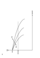
- FIG. 1 is a diagram showing an example of a life characteristic of a capacitor included in each power supply device of a power supply system according to an embodiment of the present disclosure.
- FIG. 1 is a diagram showing an overall configuration of a power supply system according to a modified example of an embodiment of the present disclosure.
- the power supply system 1 includes a plurality of power supply devices 10 and a control unit 20. Each power supply device 10 is connected to a load 2 and supplies power to the load 2. Each power supply device 10 is communicably connected to the control unit 20. As described below, the power supply system 1 has the following functions. Each power supply device 10 has a function of calculating the life of the capacitor 103 included in the power supply device 10. The control unit 20 controls the switching control circuit 108 of each power supply device 10 based on the life of the capacitor 103 calculated by each power supply device 10, and controls the current output from each power supply device 10 according to the life of the capacitor 103. Although two power supply devices 10 are shown in FIG. 1, the number of power supply devices 10 may be three or more.
- the power supply system 1 is an example of a power supply system according to the present disclosure.
- the power supply device 10 converts AC power into DC power by switching control and supplies it to the load 2.
- the power supply device 10 includes a line L1, a line L2, a transformer 101, a switch 102, a capacitor 103, a resistor 104, a temperature measurement unit 105, a voltage value measurement unit 106, a life calculation unit 107, a switching control circuit 108, and an output current measurement unit 109.
- the left side of the transformer 101 is the primary side
- the right side is the secondary side.
- the primary side is omitted from the description other than the switching control circuit 108.
- the primary side is omitted from the description other than the switching control circuit 108.
- the power supply device 10 is an example of a power supply device according to the present disclosure.
- Line L1 is connected to one end of load 2, and line L2 is connected to the other end of load 2.
- DC power is supplied to load 2 via line L1 and line L2.
- Line L1 is an example of a first line according to the present disclosure.
- Line L2 is an example of a second line according to the present disclosure.
- Transformer 101 transforms the power supplied from the primary side and supplies it to the secondary side.
- the switch 102 is an example of a switch according to the present disclosure.
- the capacitor 103 smoothes the power transformed by the transformer 101.
- the capacitor 103 is, for example, an aluminum electrolytic capacitor. Generally, as the time that a capacitor is used increases, the capacitor deteriorates and the capacitance of the capacitor decreases. According to Arrhenius' law, the higher the temperature of the capacitor, the shorter the capacitor's lifespan. In the power supply device 10, the greater the current flowing through the line L1, the higher the temperature of the capacitor 103.
- the lifespan calculation unit 107 which will be described later, calculates the lifespan of the capacitor 103 based on the capacitance and temperature of the capacitor 103. The capacitance of the capacitor 103 when not in use is known. This capacitance of the capacitor 103 when not in use is used when the lifespan calculation unit 107 calculates the lifespan of the capacitor 103.
- the capacitor 103 is an example of a capacitor according to the present disclosure.
- Resistor 104 is connected in parallel with capacitor 103. When switch 102 is off, resistor 104 discharges the charge stored in capacitor 103.
- the resistance value of resistor 104 is known. This resistance value is used when calculating the capacitance of capacitor 103 by life calculation unit 107, which will be described later.
- Resistor 104 is an example of a resistor according to the present disclosure.
- the temperature measurement unit 105 measures the temperature of the capacitor 103.
- the temperature measurement unit 105 is realized by, for example, a thermistor.
- the temperature measurement unit 105 outputs information indicating the measured temperature of the capacitor 103 to the lifetime calculation unit 107.
- the temperature measurement unit 105 is an example of a temperature measurement means according to the present disclosure.
- the voltage value measuring unit 106 measures the voltage value between both ends of the resistor 104.
- the voltage value measuring unit 106 is realized by, for example, an A/D (Analog to Digital) converter.
- the voltage value measuring unit 106 outputs information indicating the measured voltage value between both ends of the resistor 104 to the life calculation unit 107. Since the resistor 104 is connected in parallel with the capacitor 103, the voltage value measured by the voltage value measuring unit 106 is also the voltage value between both ends of the capacitor 103.
- the voltage value measuring unit 106 is an example of a voltage value measuring means according to the present disclosure.
- the life calculation unit 107 calculates the capacitance of the capacitor 103 based on the voltage value across the resistor 104 measured by the voltage value measurement unit 106 when the switch 102 is off and the known resistance value of the resistor 104. The life calculation unit 107 then calculates the life of the capacitor 103 based on the calculated capacitance of the capacitor 103 and the temperature of the capacitor 103 measured by the temperature measurement unit 105. The life calculation unit 107 outputs information indicating the calculated life to a current control unit 201 of the control unit 20 described below.
- the life calculation unit 107 is realized by, for example, a microcontroller.
- the life calculation unit 107 may also be integrated with the voltage value measurement unit 106 realized by the A/D converter described above.
- the life calculation unit 107 is an example of a life calculation means according to the present disclosure.
- the life calculation unit 107 calculates the capacity of the capacitor 103 based on formula (1).
- the life characteristics of the capacitor 103 are shown, for example, in the graph shown in FIG. 2.
- the life of the capacitor 103 is determined to be when the capacitance of the capacitor 103 reaches a predetermined capacitance. For example, when the capacitance of the capacitor 103 becomes 80% of the capacitance when the capacitor 103 is not in use, the life of the capacitor 103 is exhausted.
- the life characteristics of the capacitor vary depending on the temperature of the capacitor 103. Specifically, according to Arrhenius' law, the higher the temperature of the capacitor 103, the shorter the time required to reach the end of its life.
- the life calculation unit 107 holds data relating to the life characteristics shown in FIG. 2, and calculates the life of the capacitor 103 based on the data, the capacitance of the capacitor 103 calculated based on formula (1), and the temperature of the capacitor 103 measured by the temperature measurement unit 105.
- the switching control circuit 108 adjusts the supplied AC power on the primary side by switching control, and controls the current output to the load 2.
- the switching control circuit 108 operates based on the control by the current control unit 201 of the control unit 20 described below.
- the switching control circuit 108 is an example of a switching control circuit according to the present disclosure.
- the output current measuring unit 109 measures the current value of the current output to the line L1.
- the output current measuring unit 109 is communicatively connected to a current control unit 201 of the control unit 20, which will be described later, via wiring (not shown).
- the output current measuring unit 109 outputs a signal indicating the measured current value to the current control unit 201.
- the measured current value is used for current control by the current control unit 201. If the life calculation unit 107 is realized by a microcontroller as described above, the output current measuring unit 109 may be communicatively connected to the microcontroller instead of the current control unit 201.
- the output current measuring unit 109 outputs a signal indicating the measured current value to the microcontroller, which then outputs a signal indicating the current value to the current control unit 201.
- the output current measuring unit 109 is realized by, for example, a current sensor equipped with a Hall element.
- the control unit 20 includes a current control unit 201.
- the current control unit 201 is communicatively connected to the life calculation unit 107 and the switching control circuit 108 of each power supply device 10.
- the current control unit 201 receives a signal indicating the measured current value from the output current measurement unit 109.
- the current control unit 201 receives a signal indicating the measured current value from the microcontroller.
- the current control unit 201 controls the switching control circuit 108 based on the life of the capacitor 103 calculated by the life calculation unit 107 and the signal indicating the current value measured by the output current measurement unit 109. For example, for a power supply device 10 in which the life of the capacitor 103 is short, the current control unit 201 controls the switching circuit 108 so that the current output to the load 2 is reduced. This control prevents the temperature of the capacitor 103 from rising, thereby extending the life of the capacitor 103.
- Each power supply device 10 can calculate the life of the capacitor 103 by turning off the switch 102. Since the power supply system 1 includes multiple power supply devices 10, as long as all of the power supply devices 10 are not stopped, power supply to the load 2 can continue even if there is a power supply device 10 whose switch 102 is turned off.
- the current control section 201 of the control unit 20 can control the current for each power supply device 10 according to the life of the capacitor 103, thereby extending the life of the capacitor 103 of each power supply device 10.
- each power supply device 10 since each power supply device 10 only needs to have one switch 102, one capacitor 103, and one resistor 104, the number of parts in each power supply device can be reduced. Therefore, according to the power supply system 1, in a power supply system multiplexed with multiple power supply devices, the number of parts in each power supply device can be reduced while managing the life of the capacitors in each power supply device.
- each power supply device 10 includes the life calculation unit 107.
- the control unit 20 may include the life calculation unit 202, and the temperature measurement unit 105 and the voltage value measurement unit 106 of each power supply device 10 may output information to the life calculation unit 202.
- the life calculation unit 202 calculates the capacitance of the capacitor 103 for each power supply device 10 based on the voltage value between both ends of the resistor 104 measured by the voltage value measurement unit 106 and the resistance value of the resistor 104, and calculates the life of the capacitor 103 based on the calculated capacitance of the capacitor 103 and the temperature of the capacitor 103 measured by the temperature measurement unit 105.
- the life calculation unit 202 outputs information indicating the calculated life of the capacitor 103 of each power supply device 10 to the current control unit 201. This makes it unnecessary to provide the life calculation unit 107 in each power supply device 10, and only one life calculation unit 202 is required for one control unit, thereby further reducing the number of parts.
- the lifespan calculation unit 202 is an example of a lifespan calculation means according to the present disclosure.
- the current control section 201 of the control unit 20 may refer to schedule data related to the operation of the power supply system 1 and control the switching control circuit 108 so that the capacitor 103 does not expire on dates when maintenance of the power supply system 1 is not possible.
- the control unit 20 may be provided with a storage section that stores calendar data, and the current control section 201 may refer to the calendar data stored in the storage section and control the switching control circuit 108 of each power supply device 10 so that the capacitor 103 does not expire during long holidays when maintenance is considered impossible.
Landscapes
- Physics & Mathematics (AREA)
- General Physics & Mathematics (AREA)
- Measurement Of Resistance Or Impedance (AREA)
- Testing Electric Properties And Detecting Electric Faults (AREA)
- Dc-Dc Converters (AREA)
Priority Applications (2)
| Application Number | Priority Date | Filing Date | Title |
|---|---|---|---|
| PCT/JP2023/020109 WO2024247112A1 (ja) | 2023-05-30 | 2023-05-30 | 電源システム |
| JP2023565433A JP7466799B1 (ja) | 2023-05-30 | 2023-05-30 | 電源システム |
Applications Claiming Priority (1)
| Application Number | Priority Date | Filing Date | Title |
|---|---|---|---|
| PCT/JP2023/020109 WO2024247112A1 (ja) | 2023-05-30 | 2023-05-30 | 電源システム |
Publications (1)
| Publication Number | Publication Date |
|---|---|
| WO2024247112A1 true WO2024247112A1 (ja) | 2024-12-05 |
Family
ID=90622469
Family Applications (1)
| Application Number | Title | Priority Date | Filing Date |
|---|---|---|---|
| PCT/JP2023/020109 Ceased WO2024247112A1 (ja) | 2023-05-30 | 2023-05-30 | 電源システム |
Country Status (2)
| Country | Link |
|---|---|
| JP (1) | JP7466799B1 (https=) |
| WO (1) | WO2024247112A1 (https=) |
Citations (5)
| Publication number | Priority date | Publication date | Assignee | Title |
|---|---|---|---|---|
| JPH03135323A (ja) * | 1989-10-14 | 1991-06-10 | Mitsubishi Electric Corp | 多重電圧型インバータ装置 |
| WO2008016050A1 (fr) * | 2006-07-31 | 2008-02-07 | Mitsubishi Electric Corporation | Dispositif d'alimentation et système de séquenceur |
| JP2008236993A (ja) * | 2007-03-23 | 2008-10-02 | Toshiba Mitsubishi-Electric Industrial System Corp | 半導体電力変換システム |
| JP6121082B1 (ja) * | 2016-06-08 | 2017-04-26 | 三菱電機株式会社 | モータ制御装置 |
| JP2021145518A (ja) * | 2020-03-13 | 2021-09-24 | 東芝三菱電機産業システム株式会社 | 無停電電源システム |
Family Cites Families (2)
| Publication number | Priority date | Publication date | Assignee | Title |
|---|---|---|---|---|
| JPH11356036A (ja) * | 1998-06-04 | 1999-12-24 | Toshiba Corp | 直流電源装置 |
| JP2008164453A (ja) * | 2006-12-28 | 2008-07-17 | Mitsubishi Electric Corp | インバータ装置の平滑コンデンサ寿命判定装置 |
-
2023
- 2023-05-30 JP JP2023565433A patent/JP7466799B1/ja active Active
- 2023-05-30 WO PCT/JP2023/020109 patent/WO2024247112A1/ja not_active Ceased
Patent Citations (5)
| Publication number | Priority date | Publication date | Assignee | Title |
|---|---|---|---|---|
| JPH03135323A (ja) * | 1989-10-14 | 1991-06-10 | Mitsubishi Electric Corp | 多重電圧型インバータ装置 |
| WO2008016050A1 (fr) * | 2006-07-31 | 2008-02-07 | Mitsubishi Electric Corporation | Dispositif d'alimentation et système de séquenceur |
| JP2008236993A (ja) * | 2007-03-23 | 2008-10-02 | Toshiba Mitsubishi-Electric Industrial System Corp | 半導体電力変換システム |
| JP6121082B1 (ja) * | 2016-06-08 | 2017-04-26 | 三菱電機株式会社 | モータ制御装置 |
| JP2021145518A (ja) * | 2020-03-13 | 2021-09-24 | 東芝三菱電機産業システム株式会社 | 無停電電源システム |
Also Published As
| Publication number | Publication date |
|---|---|
| JP7466799B1 (ja) | 2024-04-12 |
| JPWO2024247112A1 (https=) | 2024-12-05 |
Similar Documents
| Publication | Publication Date | Title |
|---|---|---|
| ES2370255T3 (es) | Método y aparato para proporcionar un sistema de alimentación ininterrumpida. | |
| EP1698036B1 (en) | Maintenance free emergency lighting | |
| US8093905B2 (en) | Power supply device and sequencer system | |
| US10309841B2 (en) | Temperature detecting apparatus | |
| CN101176246B (zh) | 蓄电装置 | |
| JPWO2020084822A1 (ja) | 電圧供給システム及びそれを構成する電源、並びに当該電源を制御する方法 | |
| EP2784902A1 (en) | Direct current (DC) microgrid charge/discharge system for secondary batteries connected in series | |
| US8427849B2 (en) | Start-up circuit for power converters with wide input voltage range | |
| CN101459349A (zh) | 并联连接的不间断电源系统中的电池负载分配 | |
| KR20210025521A (ko) | Dc 링크 커패시터를 방전하기 위한 제어 장치 및 방법, 전력 변환기, 및 차량 | |
| CN103582248B (zh) | 电源装置、点亮装置、使用点亮装置的照明器具和车辆 | |
| JP2021108533A5 (https=) | ||
| ES2387540T3 (es) | Método y aparato para proporcionar alimentación ininterrumpida | |
| JP7466799B1 (ja) | 電源システム | |
| JP5304279B2 (ja) | 蓄電装置 | |
| US9080911B2 (en) | Boost converter for tracking input voltages | |
| JP2005353357A (ja) | 電子安定器 | |
| JP2007244195A (ja) | 節電装置およびその運転方法 | |
| Hart | Dc-dc converters | |
| JP2005176430A (ja) | 電源制御システム、及び該電源制御システムを用いた電子機器 | |
| JP3235134B2 (ja) | コンバータ装置の故障表示方法 | |
| US10206254B2 (en) | Signage system stabilizer circuit | |
| JP7294007B2 (ja) | 電源装置および非常用照明装置 | |
| JP2014149165A (ja) | 直流電源装置、直流電源装置における蓄電池の劣化判定方法、及び蓄電池劣化判定装置 | |
| US20250298058A1 (en) | System and method for precision current and efficiency determination in a power system |
Legal Events
| Date | Code | Title | Description |
|---|---|---|---|
| WWE | Wipo information: entry into national phase |
Ref document number: 2023565433 Country of ref document: JP |
|
| 121 | Ep: the epo has been informed by wipo that ep was designated in this application |
Ref document number: 23939591 Country of ref document: EP Kind code of ref document: A1 |
|
| NENP | Non-entry into the national phase |
Ref country code: DE |