WO2024241783A1 - 多孔質膜、積層体、及びフィルターエレメント - Google Patents
多孔質膜、積層体、及びフィルターエレメント Download PDFInfo
- Publication number
- WO2024241783A1 WO2024241783A1 PCT/JP2024/015433 JP2024015433W WO2024241783A1 WO 2024241783 A1 WO2024241783 A1 WO 2024241783A1 JP 2024015433 W JP2024015433 W JP 2024015433W WO 2024241783 A1 WO2024241783 A1 WO 2024241783A1
- Authority
- WO
- WIPO (PCT)
- Prior art keywords
- porous membrane
- less
- bubble point
- porous
- laminate
- Prior art date
- Legal status (The legal status is an assumption and is not a legal conclusion. Google has not performed a legal analysis and makes no representation as to the accuracy of the status listed.)
- Ceased
Links
Images



Classifications
-
- B—PERFORMING OPERATIONS; TRANSPORTING
- B01—PHYSICAL OR CHEMICAL PROCESSES OR APPARATUS IN GENERAL
- B01D—SEPARATION
- B01D65/00—Accessories or auxiliary operations, in general, for separation processes or apparatus using semi-permeable membranes
- B01D65/10—Testing of membranes or membrane apparatus; Detecting or repairing leaks
-
- B—PERFORMING OPERATIONS; TRANSPORTING
- B01—PHYSICAL OR CHEMICAL PROCESSES OR APPARATUS IN GENERAL
- B01D—SEPARATION
- B01D69/00—Semi-permeable membranes for separation processes or apparatus characterised by their form, structure or properties; Manufacturing processes specially adapted therefor
-
- B—PERFORMING OPERATIONS; TRANSPORTING
- B01—PHYSICAL OR CHEMICAL PROCESSES OR APPARATUS IN GENERAL
- B01D—SEPARATION
- B01D69/00—Semi-permeable membranes for separation processes or apparatus characterised by their form, structure or properties; Manufacturing processes specially adapted therefor
- B01D69/02—Semi-permeable membranes for separation processes or apparatus characterised by their form, structure or properties; Manufacturing processes specially adapted therefor characterised by their properties
-
- B—PERFORMING OPERATIONS; TRANSPORTING
- B01—PHYSICAL OR CHEMICAL PROCESSES OR APPARATUS IN GENERAL
- B01D—SEPARATION
- B01D69/00—Semi-permeable membranes for separation processes or apparatus characterised by their form, structure or properties; Manufacturing processes specially adapted therefor
- B01D69/10—Supported membranes; Membrane supports
-
- B—PERFORMING OPERATIONS; TRANSPORTING
- B01—PHYSICAL OR CHEMICAL PROCESSES OR APPARATUS IN GENERAL
- B01D—SEPARATION
- B01D69/00—Semi-permeable membranes for separation processes or apparatus characterised by their form, structure or properties; Manufacturing processes specially adapted therefor
- B01D69/12—Composite membranes; Ultra-thin membranes
- B01D69/1213—Laminated layers
-
- B—PERFORMING OPERATIONS; TRANSPORTING
- B01—PHYSICAL OR CHEMICAL PROCESSES OR APPARATUS IN GENERAL
- B01D—SEPARATION
- B01D71/00—Semi-permeable membranes for separation processes or apparatus characterised by the material; Manufacturing processes specially adapted therefor
- B01D71/06—Organic material
- B01D71/30—Polyalkenyl halides
- B01D71/32—Polyalkenyl halides containing fluorine atoms
- B01D71/36—Polytetrafluoroethylene
-
- B—PERFORMING OPERATIONS; TRANSPORTING
- B32—LAYERED PRODUCTS
- B32B—LAYERED PRODUCTS, i.e. PRODUCTS BUILT-UP OF STRATA OF FLAT OR NON-FLAT, e.g. CELLULAR OR HONEYCOMB, FORM
- B32B27/00—Layered products comprising a layer of synthetic resin
- B32B27/32—Layered products comprising a layer of synthetic resin comprising polyolefins
- B32B27/322—Layered products comprising a layer of synthetic resin comprising polyolefins comprising halogenated polyolefins, e.g. PTFE
-
- B—PERFORMING OPERATIONS; TRANSPORTING
- B01—PHYSICAL OR CHEMICAL PROCESSES OR APPARATUS IN GENERAL
- B01D—SEPARATION
- B01D2325/00—Details relating to properties of membranes
- B01D2325/02—Details relating to pores or porosity of the membranes
- B01D2325/0283—Pore size
-
- B—PERFORMING OPERATIONS; TRANSPORTING
- B01—PHYSICAL OR CHEMICAL PROCESSES OR APPARATUS IN GENERAL
- B01D—SEPARATION
- B01D2325/00—Details relating to properties of membranes
- B01D2325/22—Thermal or heat-resistance properties
Definitions
- Porous membranes containing polytetrafluoroethylene as a main component have been used as dispersion media and substrate precision filtration filters in the semiconductor-related field and other fields (Patent Documents 1 to 6, Non-Patent Document 1).
- JP 2021-54892 A International Publication No. 2007/011492 International Publication No. 2020/251909 International Publication No. 2020/251912 JP 2015-226877 A JP 2021-178948 A
- the porous membrane according to one embodiment of the present disclosure comprises: A porous membrane containing polytetrafluoroethylene as a main component,
- the porous membrane has an endothermic peak in the range of 340° C. to 350° C. in a melting curve in a first run obtained by differential scanning calorimetry at a heating rate of 10° C./min, and has an endothermic peak in the range of 320° C. to 330° C.
- the porous membrane has crystallites;
- the crystallite has a length X along the MD direction of the porous membrane and a length Y along the TD direction of the porous membrane,
- the product XY of the length X and the length Y is not less than 1200 nm2 and not more than 1710 nm2 .
- FIG. 1 is a schematic enlarged cross-sectional view of a porous membrane according to one embodiment of the present disclosure.
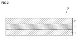
- FIG. 2 is a schematic enlarged cross-sectional view of a laminate according to an embodiment of the present disclosure.
- FIG. 3 is a perspective view of a filter element (1) according to one embodiment of the present disclosure.
- FIG. 4 is a perspective view of a filter element (2) according to one embodiment of the present disclosure.
- the porous membrane When the porous membrane is used as a pleated cartridge filter, it is folded into pleats and then heated to be heat-fixed, so the porous membrane is required to have thermal stability. This is because stretched polytetrafluoroethylene is inherently easy to shrink, and the properties (pore size and permeability) of the porous membrane are easily changed due to the shrinkage of polytetrafluoroethylene. The stretched polytetrafluoroethylene is heated in the sintering process, so that the polytetrafluoroethylene melts, and the internal stress caused by stretching is released. After that, it is cooled, and the polytetrafluoroethylene is recrystallized to form a porous membrane.
- the porous membrane containing such polytetrafluoroethylene as the main component may not have sufficient thermal stability because the melting point peak (endothermic peak) in the melting curve of the 2nd Run obtained by differential scanning calorimetry with a heating rate of 10°C/min is around 345°C.
- a laminate comprising one or more porous membranes and a support membrane located on one or both sides of at least one of the porous membranes may also have insufficient thermal stability.
- excellent "thermal stability” means that "shrinkage of the porous membrane and laminate due to heating" is unlikely to occur.
- a porous membrane containing polytetrafluoroethylene as a main component including a porous membrane containing polytetrafluoroethylene as a main component, one or more porous membranes, and a support membrane located on one or both sides of at least one of the porous membranes.
- the present disclosure therefore aims to provide a porous membrane that combines excellent thermal stability with a small pore size, a filter element that includes the porous membrane, a laminate that combines excellent thermal stability with a small pore size, and a filter element that includes the laminate.
- a porous membrane according to one embodiment of the present disclosure A porous membrane containing polytetrafluoroethylene as a main component, The porous membrane has an endothermic peak in the range of 340° C. to 350° C. in a melting curve in a first run obtained by differential scanning calorimetry at a heating rate of 10° C./min, and has an endothermic peak in the range of 320° C. to 330° C.
- the porous membrane has crystallites,
- the crystallite has a length X along the MD direction of the porous membrane and a length Y along the TD direction of the porous membrane,
- the product XY of the length X and the length Y is 1200 nm2 or more and 1710 nm2 or less.
- the present disclosure provides a porous membrane that combines excellent thermal stability with a small pore size, a filter element that includes the porous membrane, a laminate that combines excellent thermal stability with a small pore size, and a filter element that includes the laminate.
- the ratio of the absolute value of the difference between the average bubble point P1a' of the porous membrane after a test in which the porous membrane is left standing in a thermostatic bath at 120° C. for 1 hour and the average bubble point P1a of the porous membrane before the test in which the porous membrane is left standing in a thermostatic bath at 120° C. for 1 hour is 10% or less, or the ratio of the absolute value of the difference between the average bubble point P1b' of the porous membrane after the test of leaving the porous membrane in a thermostatic bath at 120° C. for 1 hour to the average bubble point P1b of the porous membrane before the test of leaving the porous membrane in a thermostatic bath at 120° C.
- the average bubble point P1a and the average bubble point P1a' are measured by a bubble point method using a 1a liquid,
- the surface tension of the first liquid is 13 mN/m;
- the average bubble point P1b and the average bubble point P1b' are measured by a bubble point method using a 1b liquid,
- the surface tension of the 1b liquid may be 21 mN/m, which makes it possible to provide a porous membrane having both superior thermal stability and a smaller pore size, a filter element including the porous membrane, a laminate having both superior thermal stability and a smaller pore size, and a filter element including the laminate.
- the average bubble point P1a is 230 kPa or more and 600 kPa or less
- the average bubble point P1b may be 500 kPa or more and 1130 kPa or less. This makes it possible to provide a porous membrane having a smaller pore size, a filter element including the porous membrane, a laminate having a smaller pore size, and a filter element including the laminate.
- the absolute value of the difference between the Gurley second G1' of the porous membrane after a test in which the porous membrane is left standing in a thermostatic chamber at 120°C for 1 hour and the Gurley second G1 of the porous membrane before the test in which the porous membrane is left standing in a thermostatic chamber at 120°C for 1 hour may be 10% or less.
- the mean flow pore size of the porous membrane may be 80 nm or less. This makes it possible to provide a porous membrane having a smaller pore size, a filter element including the porous membrane, a laminate having a smaller pore size, and a filter element including the laminate.
- a filter element according to one embodiment of the present disclosure includes a porous membrane as described in [1] to [5] above.
- the present disclosure provides a filter element having a porous membrane that combines excellent thermal stability with a small pore size.
- a laminate according to one embodiment of the present disclosure A laminate comprising one or more of the porous membranes according to the above-mentioned [1] to [5] and a support membrane located on one or both sides of at least one of the porous membranes,
- the support membrane is porous;
- the support film contains polytetrafluoroethylene as a main component.
- the present disclosure provides a laminate that combines excellent thermal stability with a small pore size, and a filter element that includes the laminate.
- a filter element according to one embodiment of the present disclosure comprises the laminate described in [7] above.
- the present disclosure provides a filter element having a laminate that combines excellent thermal stability with a small pore size.
- this embodiment is not limited thereto.
- an expression in the form of "A to B” means the upper and lower limits of a range (i.e., A or more and B or less).
- a or more and B or less the upper and lower limits of a range
- FIG. 1 A porous membrane 1 according to an embodiment of the present disclosure will be described with reference to FIG.
- One embodiment of the present disclosure (hereinafter also referred to as “the present embodiment") is
- the porous film 1 contains polytetrafluoroethylene as a main component.
- the porous membrane 1 has an endothermic peak in the range of 340°C to 350°C in the melting curve of the first run obtained by differential scanning calorimetry at a heating rate of 10°C/min, and has an endothermic peak in the range of 320°C to 330°C in the melting curve of the second run obtained by differential scanning calorimetry at a heating rate of 10°C/min. This makes it difficult for the fibers of the porous membrane to shrink. As a result, the porous membrane 1 is unlikely to experience "shrinkage due to heating," and has excellent thermal stability.
- the porous membrane 1 has a crystallite, and the crystallite has a length X along the MD (Machine Direction) direction of the porous membrane 1 and a length Y along the TD (Transverse Direction) direction of the porous membrane 1, and the product XY of the length X and the length Y is 1200 nm2 or more and 1710 nm2 or less.
- the polytetrafluoroethylene molecular chains constituting the crystallites are bound by intermolecular forces, and the thermal stability of the porous membrane is improved and the pore size of the porous membrane 1 can be suppressed small.
- a porous membrane that combines excellent thermal stability with a small pore size
- a filter element that includes the porous membrane
- a laminate that combines excellent thermal stability with a small pore size
- a filter element that includes the laminate
- the porous membrane 1 contains polytetrafluoroethylene as a main component.
- the term "main component” refers to a component with the largest content in terms of mass, for example, a component with a content of 90% by mass or more, preferably 95% by mass or more.
- the porous membrane 1 may be made of polytetrafluoroethylene.
- the phrase "the porous membrane 1 is made of polytetrafluoroethylene” means that the porous membrane 1 may contain unavoidable impurities as long as the effect of the present disclosure is achieved.
- polytetrafluoroethylene is a polymer of tetrafluoroethylene, and is a concept that includes a homopolymer of tetrafluoroethylene and a modified product of the "monopolymer of tetrafluoroethylene".
- the modified product is a tetrafluoroethylene-hexafluoropropylene copolymer (in other words, a perfluoroethylene propene copolymer.
- FEP tetrafluoroethylene-perfluoroalkyl vinyl ether copolymer
- PFA tetrafluoroethylene-perfluoroalkyl vinyl ether copolymer
- ETFE ethylene-tetrafluoroethylene copolymer
- the modified product may contain 0.1 mol % or less of hexafluoropropylene (HFP), perfluoro(alkyl vinyl ether) (FVE), or the like.
- HFP hexafluoropropylene
- FVE perfluoro(alkyl vinyl ether)
- the content of polytetrafluoroethylene can be specified based on the absorbance at 4.25 ⁇ m of "-CF 2 -” which indicates tetrafluoroethylene (TFE), the absorbance at 10.18 ⁇ m of "-CH 3 group” which indicates FEP, and the absorbance at 10.07 ⁇ m of "CF 3 O- group” which indicates PFA. It has been confirmed that the same results can be obtained even if different measurement ranges are arbitrarily selected in the same porous membrane 1.
- the thickness of the porous membrane 1 may be 0.002 mm or more and 0.100 mm or less. When the thickness is less than 0.002 mm, the strength of the porous membrane 1 tends to be insufficient. When the thickness is more than 0.100 mm, the pressure loss during permeation of the filtrate tends to be large.
- the lower limit of the thickness of the porous membrane 1 may be 0.002 mm or more, 0.005 mm or more, or 0.010 mm or more.
- the upper limit of the thickness of the porous membrane 1 may be 0.100 mm or less, 0.090 mm or less, or 0.080 mm or less.
- the thickness of the porous membrane 1 may be 0.005 mm or more and 0.090 mm or less, or 0.010 mm or more and 0.080 mm or less.
- the thickness of the porous membrane 1 can be determined by the following method. First, a standard digital thickness gauge is used to measure the thickness at one arbitrary location. Next, the same standard digital thickness gauge is used to measure the thickness at nine other arbitrary locations. Next, the average thickness value of the total of 10 locations is calculated, thereby determining the thickness of the porous membrane 1.
- the porous membrane 1 is long.
- the density of the porous membrane 1 may be 0.05 g/cm 3 or more and 2.00 g/cm 3 or less. When the density is less than 0.05 g/cm 3 , the strength of the porous membrane 1 tends to be insufficient. When the density is more than 2.00 g/cm 3 , the permeation efficiency of the porous membrane 1 tends to decrease.
- the lower limit of the density of the porous membrane 1 may be 0.05 g/cm 3 or more, 0.10 g/cm 3 or more, or 0.15 g/cm 3 or more.
- the upper limit of the density of the porous membrane 1 may be 2.00 g/cm 3 or less, 1.70 g/cm 3 or less, or 1.50 g/cm 3 or less.
- the density of the porous membrane 1 may be 0.10 g/cm 3 or more and 1.70 g/cm 3 or less, or 0.15 g/cm 3 or more and 1.50 g/cm 3 or less.
- the density of the porous membrane 1 can be determined by a method conforming to ASTM-D-792. It has been confirmed that similar results can be obtained when a different measurement range is arbitrarily selected for the same porous membrane 1 and the above measurements are performed within that measurement range.
- the basis weight of the porous membrane 1 may be 0.002 mg/mm 2 or more and 0.100 mg/mm 2 or less. When the basis weight of the porous membrane 1 is less than 0.002 mg/mm 2 , the strength of the porous membrane 1 tends to be insufficient. When the basis weight of the porous membrane 1 is more than 0.100 mg/mm 2 , the permeation efficiency of the porous membrane 1 tends to decrease.
- the lower limit of the basis weight of the porous membrane 1 may be 0.002 mg/mm 2 or more, 0.003 mg/mm 2 or more, or 0.004 mg/mm 2 or more.
- the upper limit of the basis weight of the porous membrane 1 may be 0.100 mg/mm 2 or less, 0.080 mg/mm 2 or less, or 0.060 mg/mm 2 or less.
- the basis weight of the porous membrane 1 may be 0.003 mg/mm 2 or more and 0.080 mg/mm 2 or less, or may be 0.004 mg/mm 2 or more and 0.060 mg/mm 2 or less.
- the porous membrane 1 has an endothermic peak in the range of 340°C to 350°C in the melting curve of the first run obtained by differential scanning calorimetry at a heating rate of 10°C/min, and has an endothermic peak in the range of 320°C to 330°C in the melting curve of the second run obtained by differential scanning calorimetry at a heating rate of 10°C/min. This allows the porous membrane 1 to have both excellent thermal stability and small pore size.
- the porous membrane 1 may have an endothermic peak in the range of 341°C or more, an endothermic peak in the range of 342°C or more, or an endothermic peak in the range of 343°C or more in the melting curve of the first run obtained by differential scanning calorimetry at a heating rate of 10°C/min.
- the porous membrane 1 may have an endothermic peak in the range of 349° C. or less, may have an endothermic peak in the range of 348° C. or less, or may have an endothermic peak in the range of 347° C. or less.
- the porous membrane 1 may have an endothermic peak in the range of 341° C. or more and 349° C. or less, may have an endothermic peak in the range of 342° C. or more and 348° C. or less, or may have an endothermic peak in the range of 343° C. or more and 347° C. or less.
- the porous membrane 1 may have an endothermic peak in the range of 321°C or higher, may have an endothermic peak in the range of 322°C or higher, or may have an endothermic peak in the range of 323°C or higher.
- the porous membrane 1 may have an endothermic peak in the range of 329°C or lower, may have an endothermic peak in the range of 328°C or lower, or may have an endothermic peak in the range of 327°C or lower ...
- the endothermic peak temperature (hereinafter also referred to as "endothermic peak temperature”) can be determined by the following method.
- the melting curve of the first run is obtained by heating 5 mg of the porous membrane 1 from room temperature to 400°C at a rate of 10°C/min using a differential scanning calorimeter "DSC-60A" (trademark) manufactured by Shimadzu Corporation.
- the porous membrane 1 is cooled from 400°C to 100°C at a rate of -1°C/min.
- the melting curve of the second run is obtained by heating the porous membrane 1 from 100°C to 400°C at a rate of 10°C/min using a differential scanning calorimeter "DSC-60A" (trademark) manufactured by Shimadzu Corporation.
- a melting curve for the first run is obtained.
- the endothermic peak temperatures are identified in both the melting curve for the first run and the melting curve for the second run.
- the average bubble point P1a of the porous membrane 1 before the test of leaving the porous membrane 1 in a thermostatic chamber at 120°C for 1 hour may be 230 kPa or more and 600 kPa or less. This allows the porous membrane 1 to have a smaller pore size. Therefore, the porous membrane 1 can have a better trapping performance of fine particles contained in the filtrate.
- the lower limit of the average bubble point P1a may be 230 kPa or more, 240 kPa or more, or 250 kPa or more.
- the upper limit of the average bubble point P1a may be 600 kPa or less, 590 kPa or less, or 580 kPa or less.
- the average bubble point P1a may be 240 kPa or more and 590 kPa or less, or 250 kPa or more and 580 kPa or less.
- the average bubble point P1a is measured by the bubble point method using the 1a liquid, and the surface tension of the 1a liquid is 13 mN/m. More specifically, in the porous membrane 1, the average bubble point P1a is determined by the following method. First, for a dry porous membrane 1, the differential pressure applied to the porous membrane 1 and the air flow rate passing through the porous membrane are measured based on the bubble point method (ASTM F316-86, JIS K3832). Next, in a coordinate system with the differential pressure on the horizontal axis and the air flow rate on the vertical axis, a first curve is obtained showing the relationship between the differential pressure and the numerical value obtained by dividing the air flow rate by 2.
- the porous membrane 1 is immersed in "Opteon SF70" (trademark), a hydrofluoroolefin (1a liquid) manufactured by Mitsui-Chemours Fluoroproducts, Inc., for about 5 minutes at about 25°C, and then removed from the hydrofluoroolefin (1a liquid) to obtain a porous membrane 1 wet with hydrofluoroolefin (1a liquid).
- the differential pressure applied to the porous membrane 1 and the air flow rate passing through the porous membrane 1 are measured based on the bubble point method.
- a second curve showing the relationship between the differential pressure and the air flow rate is obtained in a coordinate system with the horizontal axis representing the differential pressure and the vertical axis representing the air flow rate.
- the differential pressure at the intersection of the first curve and the second curve is specified as the average bubble point P1a.
- the surface tension of the hydrofluoroolefin (1a liquid) is 13 mN/m.
- the average bubble point P1a' of the porous membrane 1 after a test in which the porous membrane 1 is left in a thermostatic chamber at 120°C for 1 hour may be 300 kPa or more and 900 kPa or less. This allows the porous membrane 1 to have a smaller pore size. Therefore, the porous membrane 1 can have a better ability to capture fine particles contained in the filtrate.
- the lower limit of the average bubble point P1a' may be 300 kPa or more, 330 kPa or more, or 350 kPa or more.
- the upper limit of the average bubble point P1a' may be 900 kPa or less, 890 kPa or less, or 880 kPa or less.
- the average bubble point P1a' may be 330 kPa or more and 890 kPa or less, or 350 kPa or more and 880 kPa or less.
- the average bubble point P1a' is measured by a bubble point method using the 1a liquid, and the surface tension of the 1a liquid is 13 mN/m.
- the average bubble point P1a' is determined by a method similar to the measurement method of the average bubble point P1a, except that the measurement is performed on the porous membrane 1 after a test in which it is left to stand in a thermostatic bath at 120°C for 1 hour.
- the average bubble point P1b of the porous membrane 1 before the test of leaving the porous membrane 1 in a thermostatic chamber at 120°C for 1 hour may be 500 kPa or more and 1130 kPa or less. This allows the porous membrane 1 to have a smaller pore size. Therefore, the porous membrane 1 can have a better ability to capture fine particles contained in the filtrate.
- the lower limit of the average bubble point P1b may be 500 kPa or more, 510 kPa or more, or 520 kPa or more.
- the upper limit of the average bubble point P1b may be 1130 kPa or less, 1120 kPa or less, or 1110 kPa or less.
- the average bubble point P1b may be 510 kPa or more and 1120 kPa or less, or 520 kPa or more and 1110 kPa or less.
- the average bubble point P1b is measured by a bubble point method using the 1b liquid, and the surface tension of the 1b liquid is 21 mN/m. More specifically, in the porous membrane 1, the average bubble point P1b is determined in a manner similar to the measurement method for P1a, except that isopropyl alcohol (1b liquid) manufactured by Fujifilm Wako Pure Chemical Industries, Ltd. is used instead of the 1a liquid.
- the average bubble point P1b' of the porous membrane 1 after a test in which the porous membrane 1 is left in a thermostatic chamber at 120°C for 1 hour may be 250 kPa or more and 660 kPa or less. This allows the porous membrane 1 to have a smaller pore size. Therefore, the porous membrane 1 can have a better ability to capture fine particles contained in the filtrate.
- the lower limit of the average bubble point P1b' may be 250 kPa or more, 260 kPa or more, or 270 kPa or more.
- the upper limit of the average bubble point P1b' may be 660 kPa or less, 650 kPa or less, or 640 kPa or less.
- the average bubble point P1b' may be 260 kPa or more and 650 kPa or less, or 270 kPa or more and 640 kPa or less.
- the average bubble point P1b' is measured by a bubble point method using the 1b liquid, and the surface tension of the 1b liquid is 21 mN/m.
- the average bubble point P1b' is determined by a method similar to the measurement method of the average bubble point P1b, except that the measurement is performed on the porous membrane 1 after a test in which the porous membrane 1 is left to stand in a thermostatic bath at 120°C for 1 hour.
- the ratio of the absolute value of the difference between the average bubble point P1a' of the porous membrane 1 after the test of leaving the porous membrane 1 in a thermostatic bath at 120 ° C. for 1 hour and the average bubble point P1a before the test of leaving the porous membrane 1 in a thermostatic bath at 120 ° C. for 1 hour is 10% or less, or the ratio of the absolute value of the difference between the average bubble point P1b' of the porous membrane 1 after the test of leaving the porous membrane 1 in a thermostatic bath at 120 ° C. for 1 hour and the average bubble point P1b before the test of leaving the porous membrane 1 in a thermostatic bath at 120 ° C.
- the porous membrane 1 can have both better thermal stability and smaller pore size because the aggregation of the fibers of the porous membrane due to heating is suppressed and the pore size of the porous membrane is maintained in a small state.
- the lower limit of the percentage of the absolute value of the difference between the average bubble point P1a' of the porous membrane 1 after the test of leaving the porous membrane 1 in a thermostatic bath at 120°C for 1 hour and the average bubble point P1a of the porous membrane 1 before the test of leaving the porous membrane 1 in a thermostatic bath at 120°C for 1 hour is preferably closer to 0%, but can be, for example, any of 0% or more, 1% or more, and 2% or more.
- the upper limit of the percentage may be 9% or less, or 8% or less.
- the percentage may be 0% or more and 10% or less, or 0% or more and 9% or less, or 0% or more and 8% or less.
- the lower limit of the percentage of the absolute value of the difference between the average bubble point P1b' of the porous membrane 1 after the test of leaving the porous membrane 1 in a thermostatic bath at 120°C for 1 hour and the average bubble point P1b before the test of leaving the porous membrane 1 in a thermostatic bath at 120°C for 1 hour is preferably closer to 0%, but can be, for example, any of 0% or more, 1% or more, and 2% or more.
- the upper limit of the percentage may be 9% or less, or 8% or less.
- the percentage may be 0% or more and 10% or less, or 0% or more and 9% or less, or 0% or more and 8% or less.
- the average bubble point is measured by a bubble point method, in which a specific liquid is used.
- the numerical value of the average bubble point varies depending on the surface tension of the specific liquid.
- "P1a” and “P1a'” are defined as being measured by a bubble point method using "1a liquid”
- “P1b” and “P1b'” are defined as being measured by a bubble point method using "1b liquid”.
- “P2a” and “P2b” described below, and “P3a” and “P3b” described below are also defined.
- the Gurley second G1 of the porous membrane before the test of leaving the porous membrane 1 in a thermostatic chamber at 120° C. for 1 hour may be 1 second or more and 100 seconds or less. This allows the flow rate of the filtrate to be increased, so that the permeation efficiency can be increased and the capture performance of the fine particles contained in the filtrate can be improved.
- the lower limit of the Gurley second G1 may be 1 second or more, 3 seconds or more, or 5 seconds or more.
- the upper limit of the Gurley second G1 may be 100 seconds or less, 80 seconds or less, or 60 seconds or less.
- the Gurley second G1 may be 3 seconds or more and 80 seconds or less, or 5 seconds or more and 60 seconds or less.
- the Gurley second G1 can be determined by the following method. That is, the time required for 100 ml of air to permeate through a membrane effective area of 6.42 cm2 at a differential pressure of 1.22 kPa is measured according to JIS P 8117. The time is determined as the Gurley second G1.
- the Gurley second G1' of the porous membrane 1 after a test in which the porous membrane 1 is left in a thermostatic chamber at 120°C for 1 hour may be 1 second or more and 100 seconds or less. This allows the flow rate of the filtrate to be increased, thereby increasing the permeation efficiency and improving the capture performance of fine particles contained in the filtrate.
- the lower limit of the Gurley second G1' may be 1 second or more, 3 seconds or more, or 5 seconds or more.
- the upper limit of the Gurley second G1' may be 100 seconds or less, 80 seconds or less, or 60 seconds or less.
- the Gurley second G1' may be 3 seconds or more and 80 seconds or less, or 5 seconds or more and 60 seconds or less.
- the Gurley second G1' can be determined by a method similar to that for measuring the Gurley second G1, except that the measurement is performed on the porous membrane 1 after a test in which it is left in a thermostatic chamber at 120°C for 1 hour.
- the absolute value of the difference between the Gurley second G1' of the porous membrane 1 after the test of leaving the porous membrane 1 in a thermostatic chamber at 120°C for 1 hour and the Gurley second G1 of the porous membrane 1 before the test of leaving the porous membrane 1 in a thermostatic chamber at 120°C for 1 hour may be 10% or less in percentage. This suppresses the aggregation of the fibers of the porous membrane 1 due to heating, and the pore size of the porous membrane is maintained in a small state, so that the porous membrane 1 can have both better thermal stability and smaller pore size.
- the lower limit of the ratio is preferably closer to 0% in percentage, but can be, for example, any of 0% or more, 1% or more, and 2% or more.
- the upper limit of the ratio may be 9% or less, or 8% or less in percentage.
- the ratio may be 0% or more and 10% or less in percentage, or 0% or more and 9% or less in percentage, or 0% or more and 8% or less in percentage.
- the mean flow pore size of the porous membrane 1 may be 80 nm or less. This allows the porous membrane 1 to have a smaller pore size. Therefore, the porous membrane 1 can have a better trapping performance of fine particles contained in the filtrate.
- the lower limit of the mean flow pore size may be 25 nm or more, 26 nm or more, or 27 nm or more.
- the upper limit of the mean flow pore size may be 80 nm or less, 60 nm or less, or 50 nm or less.
- the mean flow pore size may be 25 nm or more and 80 nm or less, 26 nm or more and 60 nm or less, or 27 nm or more and 50 nm or less.
- the average flow pore size of the porous membrane 1 can be determined by the following measurement method. That is, first, for the dry porous membrane 1, the differential pressure applied to the porous membrane 1 and the air flow rate passing through the porous membrane 1 are measured based on the bubble point method. Next, in a coordinate system with the differential pressure on the horizontal axis and the air flow rate on the vertical axis, a third curve showing the relationship between the differential pressure and the numerical value obtained by dividing the air flow rate by 2 is obtained.
- the porous membrane 1 that has been immersed in GALWICK (propylene, 1,1,2,3,3,3-hexafluorofluoride oxide, fourth liquid) manufactured by Porous Materials for about 5 minutes at about 25°C is taken out of GALWICK (fourth liquid) to obtain a porous membrane 1 wet with GALWICK (fourth liquid).
- GALWICK propylene, 1,1,2,3,3,3-hexafluorofluoride oxide, fourth liquid
- the differential pressure applied to the porous membrane 1 and the air flow rate passing through the porous membrane 1 are measured based on the bubble point method.
- a fourth curve showing the relationship between the differential pressure and the air flow rate is obtained in a coordinate system with the horizontal axis representing the differential pressure and the vertical axis representing the air flow rate.
- the differential pressure P' at the intersection of the third curve and the fourth curve is identified.
- the average flow pore size [nm] of the porous membrane 1 is obtained by dividing the product of the constant 2860 and the surface tension of the fourth liquid, 16 mN, by the differential pressure P'.
- a PMI Perm Porometer "CFP-1500A" is used as a pore diameter distribution measuring device.
- the porous membrane 1 has a crystallite, and the crystallite has a length X along the MD direction of the porous membrane 1 and a length Y along the TD direction of the porous membrane 1.
- the term "crystallite” refers to the smallest unit portion of a crystal grain that can be regarded as a single crystal.
- the upper limit of the length X along the MD direction of the porous membrane 1 may be less than 60 nm. When the length X along the MD direction of the porous membrane 1 is 60 nm or more, the pore size tends to increase and the capturing performance of fine particles tends to decrease.
- the upper limit of the length X along the MD direction of the porous membrane 1 may be less than 59 nm or less than 58 nm.
- the lower limit of the length X along the MD direction of the porous membrane 1 is not particularly limited, but may be, for example, 5 nm or more, 7 nm or more, or 10 nm or more.
- the "MD direction" can be rephrased as the long length direction.
- the "TD direction” described later can be rephrased as the direction perpendicular to the above-mentioned "MD direction” and the thickness direction of the porous membrane 1.
- the length X of the porous membrane 1 along the MD direction can be determined by X-ray diffraction measurement.
- BL16 of the synchrotron radiation facility SAGA-LS is used for the X-ray diffraction measurement.
- a double crystal spectrometer using Si (111) diffraction is used to monochromatize the X-ray wavelength to 0.124 nm.
- the measurement is performed by the transmission method, and a double slit optical system is used with a NaI scintillation counter as a detector.
- the receiving slits are all 0.5 mm long (diffraction angle measurement direction) and 3 mm wide (vertical direction).
- the upper limit of the length Y of the porous membrane 1 along the TD direction may be less than 60 nm. If the length Y of the porous membrane 1 along the TD direction is 60 nm or more, the pore size tends to become large and the microparticle capture performance tends to decrease.
- the upper limit of the length Y of the porous membrane 1 along the TD direction may be less than 59 nm, or may be less than 58 nm.
- the lower limit of the length Y of the porous membrane 1 along the TD direction is not particularly limited, but can be, for example, 5 nm or more, 7 nm or more, or 10 nm or more.
- the length Y of the porous film 1 along the TD direction can be determined by X-ray diffraction measurement.
- BL16 of the synchrotron radiation facility SAGA-LS is used for the X-ray diffraction measurement.
- a double crystal spectrometer using Si (111) diffraction is used to monochromatize the X-ray wavelength to 0.124 nm.
- the measurement is performed by the transmission method, and a double slit optical system is used with a NaI scintillation counter as a detector.
- the light receiving slits are all 0.5 mm long (diffraction angle measurement direction) and 3 mm wide (vertical direction).
- the X-ray diffraction measurement is performed after measuring the above-mentioned "length X along the MD direction of the porous film 1" and then rotating the porous film 1 by 90° along a virtual plane perpendicular to the film thickness direction of the porous film 1.
- B2 peak integral width of the polytetrafluoroethylene (100) diffraction line of the obtained XRD profile and ⁇ 2, which is 1/2 of the Bragg angle 2 ⁇ 2, which is the peak position
- ⁇ 2 means the wavelength of X-rays and is 0.124 nm.
- Y ⁇ 2/(B2cos ⁇ 2) Equation 4
- the product XY of the length X and the length Y is 1200 nm2 or more and 1710 nm2 or less. This improves the thermal stability of the porous film 1 and keeps the pore diameter of the porous film 1 small.
- the upper limit of the product XY of the length X and the length Y may be 1700 nm2 or less, or may be 1690 nm2 or less.
- the lower limit of the product XY of the length X and the length Y is not particularly limited, but may be, for example, 30 nm2 or more, 50 nm2 or more, or 100 nm2 or more.
- the crystallite may be made of polytetrafluoroethylene. This makes it easier for the crystallite density of the porous membrane 1 to be high in crystallinity, and therefore it can have both better thermal stability and smaller pore size.
- "made of polytetrafluoroethylene” is not limited to the embodiment of only polytetrafluoroethylene, but also includes the embodiment of containing components other than polytetrafluoroethylene (for example, inevitable impurities) as long as the effect of the present disclosure is achieved.
- the method for producing the porous film according to the present embodiment includes the steps of: 1-1 step of obtaining a kneaded product of polytetrafluoroethylene powder and liquid lubricant; 1-2 step of obtaining a sheet-like molded body by extrusion molding the kneaded product; 1-3 step of obtaining an elongated body by biaxially stretching the molded body; and 1-4 step of obtaining a porous film by heat treatment of the elongated body.
- the 1-4 step is carried out under the conditions of 345°C or higher and 3 minutes or less.
- Step 1-1 is carried out by kneading a polytetrafluoroethylene powder with a liquid lubricant to obtain a kneaded product. More specifically, first, a mixture is obtained by mixing the polytetrafluoroethylene powder with the liquid lubricant. Next, the mixture is compression molded into a block shape using a compression molding machine to obtain the kneaded product.
- Polytetrafluoroethylene powder refers to a powder consisting of fine particles of polytetrafluoroethylene.
- Examples of polytetrafluoroethylene powder include "PTFE (polytetrafluoroethylene) fine powder” produced by emulsion polymerization, and "PTFE molding powder” produced by suspension polymerization.
- the number average molecular weight of polytetrafluoroethylene in the polytetrafluoroethylene powder may be 12 million or more and 50 million or less, from the viewpoint of being able to promote the growth of the fibrous skeleton while preventing excessive expansion of the pore size during stretching and rupture of the porous film.
- the second heat of fusion in the polytetrafluoroethylene powder may be 10 J/g or more and 25 J/g or less, from the viewpoint of being dependent on the number average molecular weight of the polytetrafluoroethylene powder.
- the second heat of fusion can be specified by the following method.
- the polytetrafluoroethylene powder is heated from room temperature to 380°C at a rate of 10°C/min (Pattern 1 (1st Run)), then cooled from 380°C to 100°C at a rate of -1°C/min (Pattern 2), and then heated from 100°C to 380°C at a rate of 10°C/min (Pattern 3 (2nd Run)).
- the end set temperature of the peak in the range of 300°C to 360°C of the melting curve of pattern 3 is taken as the starting point, and the endothermic heat obtained by integrating the section of 48°C is taken as the second heat of fusion.
- the "end set temperature” here means the temperature at the end of melting with the rise in temperature in the relationship between the melting curve and the peak.
- liquid lubricants various lubricants that have been used in the extrusion method can be used.
- liquid lubricants include petroleum solvents such as solvent naphtha and white oil, hydrocarbon oils such as undecane, aromatic hydrocarbons such as toluene and xylol, alcohols, ketones, esters, silicone oil, fluorochlorocarbon oil, solutions of polymers such as polyisobutylene and polyisoprene dissolved in these solvents, water or aqueous solutions containing surfactants, etc.
- solvents such as solvent naphtha and white oil
- hydrocarbon oils such as undecane
- aromatic hydrocarbons such as toluene and xylol
- alcohols ketones
- esters such as toluene and xylol
- silicone oil such as toluene and xylol
- fluorochlorocarbon oil solvents
- solutions of polymers such as polyisobutylene and polyisoprene
- the mass parts of the liquid lubricant per 100 mass parts of polytetrafluoroethylene powder may be 10 parts by mass or more and 40 parts by mass or less. If the mass parts of the liquid lubricant are less than 10 parts by mass, extrusion tends to be difficult. If the mass parts of the liquid lubricant are more than 40 parts by mass, compression molding tends to be difficult.
- additives may be used as materials for the kneaded product.
- examples of other additives include pigments for coloring, carbon black for improving abrasion resistance, preventing low-temperature flow, and facilitating pore formation, graphite, silica powder, glass powder, glass fiber, inorganic fillers such as silicates and carbonates, metal powder, metal oxide powder, and metal sulfide powder.
- substances that can be removed or decomposed by heating, extraction, dissolution, etc. such as ammonium chloride, sodium chloride, plastics other than polytetrafluoroethylene, and rubber, may be used in the form of a powder or solution.
- the 1-2 step is carried out by extruding the kneaded material to obtain a sheet-like molded body. More specifically, the kneaded material is extruded into a sheet at room temperature (for example, 25°C) or higher and 50°C or lower, and at a speed of, for example, 10 mm/min to 30 mm/min to obtain a precursor of the sheet-like molded body. Furthermore, the precursor is rolled with a calendar roll or the like to obtain a sheet-like molded body having an average thickness of 0.200 mm to 0.400 mm. The average thickness can be specified in the same manner as the thickness of the porous membrane 1, except that the measurement is performed on the molded body.
- the liquid lubricant contained in the molded body may be removed.
- the liquid lubricant can be removed by heating, extracting, dissolving, or the like, the molded body.
- the molded body can be rolled with a heated roll at 130°C or higher and 220°C or lower to remove the liquid lubricant from the molded body.
- liquid lubricants with relatively high boiling points such as silicone oil and fluorochlorocarbon oil, removal by extraction is preferable.
- Step 1-3 is carried out by biaxially stretching the molded body to obtain a stretched body.
- biaxial stretching means stretching the sheet-like molded body in the MD direction (in other words, the flow direction of the molded body) and the TD direction perpendicular to the MD direction.
- the temperature in steps 1-3 may be 60°C or higher and 300°C or lower. If the temperature is higher than 300°C, the pore size of the porous membrane tends to become too large (in other words, the average bubble point of the porous membrane tends to become too small). If the temperature is lower than 60°C, the pore size tends to become too small (in other words, the average bubble point of the porous membrane tends to become too large).
- the stretching ratio in the MD direction may be 1.5 times or more and 20 times or less.
- the stretching ratio in the MD direction means a value obtained by dividing the average length in the MD direction immediately after stretching in the MD direction by the average length in the MD direction immediately before stretching in the MD direction. If the stretching ratio in the MD direction is less than 1.5 times, the thickness of the porous film may be outside the desired range. If the stretching ratio in the MD direction is more than 20 times, the thickness of the porous film may be outside the desired range.
- the "average length in the MD direction” means the average value of the length in the MD direction at any 10 points.
- the stretching ratio in the TD direction may be 1.5 times or more and 100 times or less.
- the stretching ratio in the TD direction means a value obtained by dividing the average length in the TD direction immediately after stretching in the TD direction by the average length in the TD direction immediately before stretching in the TD direction. If the stretching ratio in the TD direction is less than 1.5 times, the thickness of the porous film may be outside the desired range. If the stretching ratio in the TD direction is more than 100 times, the thickness of the porous film may be outside the desired range.
- the "average length in the TD direction" means the average value of the length in the TD direction at any 10 points.
- the 1-4 step is carried out by subjecting the stretched body to a heat treatment to obtain a porous film.
- the 1-4 step is carried out under the conditions of 345°C or higher and 3 minutes or less.
- the porous film has an endothermic peak in the range of 340°C to 350°C in the melting curve of the 1st run obtained by differential scanning calorimetry at a heating rate of 10°C/min, and has an endothermic peak in the range of 320°C to 330°C in the melting curve of the 2nd run obtained by differential scanning calorimetry at a heating rate of 10°C/min
- the porous film has crystallites, the crystallites have a length X along the MD direction of the porous film and a length Y along the TD direction of the porous film, and the product XY of the length X and the length Y can be 1200 nm2 or more and 1710 nm2 or less.
- the upper limit of the temperature in steps 1-4 may be 800°C or lower. If the temperature exceeds 800°C, the mechanical strength of the porous film tends to decrease due to thermal decomposition of polytetrafluoroethylene.
- the lower limit of the time for step 1-4 may be 0.01 minutes or more. If the time is less than 0.01 minutes, the thermal stability of the porous membrane tends to decrease.
- a porous film containing polytetrafluoroethylene as a main component can be obtained, and the porous film has an endothermic peak in the range of 340°C to 350°C in the melting curve of the first run obtained by differential scanning calorimetry at a heating rate of 10°C/min, and has an endothermic peak in the range of 320°C to 330°C in the melting curve of the second run obtained by differential scanning calorimetry at a heating rate of 10°C/ min , and the porous film has crystallites, and the crystallites have a length X along the MD direction of the porous film and a length Y along the TD direction of the porous film, and the product XY of the length X and the length Y is 1200 nm2 or more and 1710 nm2 or less.
- the filter element 500 according to this embodiment includes the porous membrane 570 according to embodiment 1.
- the filter element 500 according to this embodiment is not particularly limited as long as it includes the porous membrane 570 according to embodiment 1, but for example, in the filter element 500, the porous membrane 570 may have a pleated structure.
- a filter element 500 is shown that includes a porous membrane 570 having a pleated structure.
- the porous membrane 570 is sandwiched between two protective materials 520, 540 and folded in pleats, and wrapped around a core 550 that has a number of liquid collection ports 590.
- An outer peripheral guard 510 is provided on the outside to protect the porous membrane 570.
- the porous membrane 570 is sealed at both ends of the cylinder by end plates 560a, 560b. The end plates contact the seal parts of the filter housing (not shown) via gaskets 600.
- the filtered liquid is collected from the liquid collection ports 590 of the core 550 and recovered from the outlet 580.
- the method for producing the filter element according to this embodiment can be carried out in the same manner as the conventionally known method, except that the porous membrane according to the first embodiment is used.
- the laminate 10 includes one or more porous membranes 1 according to embodiment 1. This allows the laminate 10 to have both excellent thermal stability and a small pore size.
- the laminate 10 also includes a support membrane 2 located on one or both sides of at least one of the porous membranes 1. This allows the support membrane 2 to function as a protective material for the porous membrane 1 according to embodiment 1, thereby improving the capture performance of the laminate 10 and increasing the mechanical strength and life of the laminate 10.
- the thickness of the laminate 10 may be 0.010 mm or more and 0.200 mm or less. If the thickness is less than 0.010 mm, the strength of the laminate 10 tends to be insufficient. If the thickness is more than 0.200 mm, the pressure loss during permeation of the filtrate tends to be large.
- the lower limit of the thickness of the laminate 10 may be 0.010 mm or more, 0.013 mm or more, or 0.015 mm or more.
- the upper limit of the thickness of the laminate 10 may be 0.200 mm or less, 0.150 mm or less, or 0.100 mm or less.
- the thickness of the laminate 10 may be 0.013 mm or more and 0.150 mm or less, or 0.015 mm or more and 0.100 mm or less.
- the thickness of the laminate 10 can be determined in a manner similar to the method for measuring the thickness of the porous membrane 1, except that the measurement is performed on the laminate 10. It has been confirmed that similar results can be obtained when different measurement points are arbitrarily selected on the same laminate 10 and the above measurement is performed at those measurement points.
- the density of the laminate 10 may be 0.10 g/cm 3 or more and 2.00 g/cm 3 or less. When the density is less than 0.10 g/cm 3 , the strength of the laminate 10 tends to be insufficient. When the density is more than 2.00 g/cm 3 , the transmission efficiency of the laminate 10 tends to decrease.
- the lower limit of the density of the laminate 10 may be 0.10 g/cm 3 or more, 0.13 g/cm 3 or more, or 0.15 g/cm 3 or more.
- the upper limit of the density of the laminate 10 may be 2.00 g/cm 3 or less, 1.70 g/cm 3 or less, or 1.50 g/cm 3 or less.
- the density of the laminate 10 may be 0.13 g/cm 3 or more and 1.70 g/cm 3 or less, or 0.15 g/cm 3 or more and 1.50 g/cm 3 or less.
- the density of the laminate 10 can be determined by a method similar to the "Method of measuring the density of the porous membrane 1" described in embodiment 1, except that the measurement is performed on the "laminated body 10." It has been confirmed that similar results can be obtained by arbitrarily selecting different measurement ranges in the same laminate 10 and performing the above measurements in those measurement ranges.
- the basis weight of the laminate 10 may be 0.005 mg/mm 2 or more and 0.100 mg/mm 2 or less. When the basis weight of the laminate 10 is less than 0.005 mg/mm 2 , the strength of the laminate 10 tends to be insufficient. When the basis weight of the laminate 10 is more than 0.100 mg/mm 2 , the permeability efficiency of the laminate 10 tends to decrease.
- the lower limit of the basis weight of the laminate 10 may be 0.005 mg/mm 2 or more, 0.007 mg/mm 2 or more, or 0.008 mg/mm 2 or more.
- the upper limit of the basis weight of the laminate 10 may be 0.100 mg/mm 2 or less, 0.080 mg/mm 2 or less, or 0.060 mg/mm 2 or less.
- the basis weight of the laminate 10 may be 0.007 mg/mm 2 or more and 0.080 mg/mm 2 or less, or may be 0.008 mg/mm 2 or more and 0.060 mg/mm 2 or less.
- the basis weight of the laminate 10 can be determined by a method similar to the "method of measuring the basis weight of the porous membrane 1" described in embodiment 1, except that the measurement is performed on the "laminate 10." It has been confirmed that similar results can be obtained by arbitrarily selecting different measurement ranges in the same laminate 10 and performing the above measurements in those measurement ranges.
- the average bubble point P2a of the laminate 10 may be 400 kPa or more and 900 kPa or less, or the average bubble point P2b of the laminate 10 may be 800 kPa or more and 1300 kPa or less. This makes it possible to have both a better trapping performance for fine particles contained in the filtrate and a better permeation efficiency.
- the average bubble point P2a of the laminate 10 may be 400 kPa or more and 900 kPa or less. This allows for both better trapping performance of fine particles contained in the filtrate and better permeability.
- the lower limit of the average bubble point P2a may be 400 kPa or more, 410 kPa or more, or 420 kPa or more.
- the upper limit of the average bubble point P2a may be 900 kPa or less, 890 kPa or less, or 880 kPa or less.
- the average bubble point P2a may be 410 kPa or more and 890 kPa or less, or 420 kPa or more and 880 kPa or less.
- the average bubble point P2a is measured by the bubble point method using the 2a liquid, and the surface tension of the 2a liquid is 13 mN/m. More specifically, in the laminate 10, the average bubble point P2a is determined by the following method. More specifically, in the laminate 10, P2a is determined by a method similar to the measurement method of P1a, except that the measurement is performed on the "laminate 10" and the name of the liquid "1a liquid” is replaced with "2a liquid".
- the average bubble point P2b of the laminate 10 may be 800 kPa or more and 1300 kPa or less. This allows for both better trapping performance of fine particles contained in the filtrate and better permeability efficiency.
- the lower limit of the average bubble point P2b may be 800 kPa or more, 810 kPa or more, or 820 kPa or more.
- the upper limit of the average bubble point P2b may be 1300 kPa or less, 1290 kPa or less, or 1280 kPa or less.
- the average bubble point P2b may be 810 kPa or more and 1290 kPa or less, or 820 kPa or more and 1280 kPa or less.
- the average bubble point P2b is measured by a bubble point method using the second b liquid, and the surface tension of the second b liquid is 21 mN/m. More specifically, in the laminate 10, the average bubble point P2b is determined in a manner similar to the measurement method for P2a, except that isopropyl alcohol (second b liquid) manufactured by FUJIFILM Wako Pure Chemical Industries, Ltd. is used instead of the second a liquid.
- isopropyl alcohol (second b liquid) manufactured by FUJIFILM Wako Pure Chemical Industries, Ltd. is used instead of the second a liquid.
- Gurley Seconds The laminate 10 has a Gurley second G2, which may be 1 second or more and 100 seconds or less. This allows the flow rate of the filtrate to be increased, thereby increasing the permeation efficiency and enhancing the ability to capture fine particles contained in the filtrate.
- the lower limit of the Gurley second G2 may be 1 second or more, 3 seconds or more, or 5 seconds or more.
- the upper limit of the Gurley second G2 may be 100 seconds or less, 80 seconds or less, or 70 seconds or less.
- the Gurley second G2 may be 3 seconds or more and 80 seconds or less, or 5 seconds or more and 70 seconds or less.
- the Gurley second G2 is determined by the following method. That is, except that the measurement is performed on the "laminated body 10", it can be determined by the same method as the "method of measuring the Gurley second G1" in embodiment 1.
- the mean flow pore size of the laminate 10 may be 25 nm or more and 100 nm or less. This allows the laminate 10 to have a smaller pore size. Therefore, the laminate 10 can have a better trapping performance of fine particles contained in the filtrate.
- the lower limit of the mean flow pore size may be 25 nm or more, 26 nm or more, or 27 nm or more.
- the upper limit of the mean flow pore size may be 100 nm or less, 60 nm or less, or 55 nm or less.
- the mean flow pore size may be 26 nm or more and 60 nm or less, or 27 nm or more and 55 nm or less.
- the mean flow pore size of the laminate 10 can be determined in a manner similar to the "Method of measuring the mean flow pore size of the porous membrane 1" in embodiment 1, except that the measurement is performed on the "laminated body 10.”
- the support membrane 2 is porous.
- porous means that the support membrane 2 has a fibrous skeleton in which pores are connected in a three-dimensional network.
- the support membrane 2 has a larger pore size than the porous membrane 1, and does not necessarily inhibit the permeation efficiency.
- the support membrane 2 is porous can be determined by observing the surface state and cross-sectional state of the support membrane 2 using a scanning electron microscope.
- the thickness of the support film 2 may be 0.002 mm or more and 0.050 mm or less. If the thickness of the support film 2 is less than 0.002 mm, the function of the porous film 1 as a protective material tends to be difficult to exert, and the mechanical strength of the laminate 10 and the life of the laminate 10 tend to be difficult to increase. If the thickness of the support film 2 exceeds 0.050 mm, the porous film 1 tends to be difficult to achieve both the capture performance of the laminate 10 and the permeation efficiency of the laminate 10. The lower limit of the thickness may be 0.002 mm or more, 0.004 mm or more, or 0.006 mm or more.
- the upper limit of the thickness may be 0.050 mm or less, 0.045 mm or less, or 0.040 mm or less.
- the thickness may be 0.004 mm or more and 0.045 mm or less, or 0.006 mm or more and 0.040 mm or less.
- the thickness may be 0.004 mm or more and 0.045 mm or less, or 0.006 mm or more and 0.040 mm or less.
- the thickness of the support membrane 2 can be determined in a manner similar to the measurement method for the "thickness of the porous membrane 1" described in embodiment 1, except that the measurement is performed on the support membrane 2. It has been confirmed that similar results can be obtained when different measurement points are arbitrarily selected on the same support membrane 2 and the above measurement is performed at the selected measurement points.
- the density of the support film 2 may be 0.10 g/cm 3 or more and 2.00 g/cm 3 or less. When the density is less than 0.10 g/cm 3 , the strength of the laminate 10 tends to be insufficient. When the density is more than 2.00 g/cm 3 , the permeability efficiency of the laminate 10 tends to decrease.
- the lower limit of the density of the support film 2 may be 0.10 g/cm 3 or more, 0.13 g/cm 3 or more, or 0.15 g/cm 3 or more.
- the upper limit of the density of the support film 2 may be 2.00 g/cm 3 or less, 1.70 g/cm 3 or less, or 1.50 g/cm 3 or less.
- the density of the support film 2 may be 0.13 g/cm 3 or more and 1.70 g/cm 3 or less, or 0.15 g/cm 3 or more and 1.50 g/cm 3 or less.
- the density of the support membrane 2 can be determined by a method similar to that for measuring the density of the porous membrane 1, except that the measurement is performed on the "support membrane 2." It has been confirmed that similar results can be obtained by arbitrarily selecting a different measurement range for the same support membrane 2 and performing the above measurement in that measurement range.
- the basis weight of the support film 2 may be 0.005 mg/mm 2 or more and 0.100 mg/mm 2 or less. When the basis weight of the support film 2 is less than 0.005 mg/mm 2 , the strength of the laminate 10 tends to be insufficient. When the basis weight of the support film 2 is more than 0.100 mg/mm 2 , the permeability efficiency of the laminate 10 tends to decrease.
- the lower limit of the basis weight of the support film 2 may be 0.005 mg/mm 2 or more, 0.006 mg/mm 2 or more, or 0.007 mg/mm 2 or more.
- the upper limit of the basis weight of the support film 2 may be 0.100 mg/mm 2 or less, 0.080 mg/mm 2 or less, or 0.060 mg/mm 2 or less.
- the basis weight of the support film 2 may be 0.006 mg/mm 2 or more and 0.080 mg/mm 2 or less, or may be 0.007 mg/mm 2 or more and 0.060 mg/mm 2 or less.
- the basis weight of the support membrane 2 can be determined by the following method. Except for the fact that the measurement is performed on the "support membrane 2", it can be determined by the same method as the method for measuring the basis weight of the porous membrane 1. It has been confirmed that similar results can be obtained when a different measurement range is arbitrarily selected for the same support membrane 2 and the above measurement is performed in that measurement range.
- the average bubble point P3a of the support film 2 may be 5 kPa or more and 400 kPa or less, or the average bubble point P3b of the support film 2 may be 5 kPa or more and 800 kPa or less, thereby enabling the laminate 10 to have a smaller pore size.
- the average bubble point P3a of the support film 2 may be 5 kPa or more and 400 kPa or less. This allows the laminate 10 to have a smaller pore size. Therefore, the laminate 10 can have better trapping performance for fine particles contained in the filtrate.
- the lower limit of P3a may be 5 kPa or more, 7 kPa or more, or 10 kPa or more.
- the upper limit of P3a may be 400 kPa or less, 350 kPa or less, or 300 kPa or less.
- P3a may be 7 kPa or more and 350 kPa or less, or 10 kPa or more and 300 kPa or less.
- P3a is measured by the bubble point method using the 3a liquid, and the surface tension of the 3a liquid is 13 mN/m. More specifically, in the support film 2, P3a is determined in a manner similar to the measurement method of P1a, except that the measurement is performed on the "support film 2" and the name of the liquid “1a liquid” is replaced with "3a liquid”.
- the average bubble point P3b of the support film 2 may be 5 kPa or more and 800 kPa or less. This allows the laminate 10 to have a smaller pore size. Therefore, the laminate 10 can have better trapping performance for fine particles contained in the filtrate.
- the lower limit of P3b may be 5 kPa or more, 7 kPa or more, or 10 kPa or more.
- the upper limit of P3b may be 800 kPa or less, 700 kPa or less, or 600 kPa or less.
- P3b may be 7 kPa or more and 700 kPa or less, or 10 kPa or more and 600 kPa or less.
- P3b is measured by the bubble point method using the 3b liquid, and the surface tension of the 3b liquid is 21 mN/m. More specifically, in the support film 2, P3b is determined in a manner similar to the measurement method for P3a, except that isopropyl alcohol (3b liquid) manufactured by FUJIFILM Wako Pure Chemical Industries, Ltd. is used instead of the 3a liquid.
- the support membrane 2 has a Gurley second G3.
- G3 may be 0.5 seconds or more and 60 seconds or less. This allows the flow rate of the filtrate to be increased, so that the permeation efficiency can be increased and the capture performance of fine particles contained in the filtrate can be improved.
- the lower limit of G3 may be 0.5 seconds or more, 0.7 seconds or more, or 1.0 seconds or more.
- the upper limit of G3 may be 60 seconds or less, 50 seconds or less, or 40 seconds or less.
- G3 may be 0.7 seconds or more and 50 seconds or less, or 1.0 seconds or more and 40 seconds or less.
- G3 is determined by the following method. Except for the fact that the measurement is performed on the "support membrane 2", it can be determined by the same method as the "Method of measuring G1 of the porous membrane 1" in embodiment 1.
- the mean flow pore size of the support film 2 may be 45 nm or more and 600 nm or less. This allows the laminate 10 to have a smaller pore size. Therefore, the laminate 10 can have a better trapping performance of fine particles contained in the filtrate.
- the lower limit of the mean flow pore size may be 45 nm or more, 50 nm or more, or 55 nm or more.
- the upper limit of the mean flow pore size may be 600 nm or less, 550 nm or less, or 500 nm or less.
- the mean flow pore size may be 50 nm or more and 550 nm or less, or 55 nm or more and 500 nm or less.
- the mean flow pore size of the support membrane 2 can be determined by the following measurement method. Except for the fact that the measurement is performed on the "support membrane 2", it can be determined by the same method as the "Method of measuring the mean flow pore size of the porous membrane 1" in embodiment 1.
- the support film 2 contains polytetrafluoroethylene as a main component. This can improve the heat resistance and chemical stability of the support film 2.
- the "main component” refers to the component with the largest content in terms of mass, for example, a component with a content of 90 mass% or more, preferably 95 mass% or more.
- the support film 2 may be made of polytetrafluoroethylene.
- the phrase "the support film 2 is made of polytetrafluoroethylene” means that the support film 2 may contain inevitable impurities as long as the effects of the present disclosure are achieved.
- the polytetrafluoroethylene content in the support membrane 2 can be determined by a method similar to the measurement method for "polytetrafluoroethylene content in the porous membrane 1" described in embodiment 1, except that the measurement is performed on the support membrane 2. It has been confirmed that similar results can be obtained by arbitrarily selecting a different measurement range in the same support membrane 2 and performing the above measurement in that measurement range.
- the method for producing the laminate includes a step 2-1 of preparing the porous membrane according to embodiment 1 and a support membrane, and a step 2-2 of laminating the porous membrane on the support membrane.
- the step 2-1 includes a step 2-1-a of preparing the porous membrane and a step 2-1-b of preparing the support membrane.
- Step 2-1-a is carried out by preparing a porous membrane.
- the porous membrane 1 can be prepared by the method described in the first embodiment.
- Step 2-1-b is carried out by preparing a support film.
- the support film can be prepared by a conventionally known method.
- Step 2-2 is carried out by laminating a porous membrane on one or both sides of a support membrane.
- a method for laminating a porous membrane on one or both sides of a support membrane for example, a method of pressing the support membrane and the porous membrane can be mentioned.
- the method of bonding the support film and the porous film is, for example, to obtain a laminate precursor by overlapping the support film and the porous film.
- the laminate precursor is then pressed from above and below with flat plates, or the laminate precursor is sandwiched from above and below with rotating rollers and sent out.
- the method of bonding the support film and the porous film may be performed by bonding with a pressure of 10 kgf or more and 2000 kgf or less. If the pressure is less than 10 kgf, the adhesive strength between the support film and the porous film tends to be insufficient. If the pressure is more than 2000 kgf, the pores of the support film and the porous film tend to be crushed, and the permeation efficiency tends to be easily reduced.
- a laminate can be obtained that includes one or more porous membranes according to embodiment 1 and a support membrane located on one or both sides of at least one of the porous membranes, the support membrane being porous and containing polytetrafluoroethylene as a main component.
- the filter element 500 according to this embodiment includes the laminate 670 according to embodiment 3.
- the filter element 500 according to this embodiment is not particularly limited as long as it includes the laminate 670 according to embodiment 3, but for example, in the filter element 500, the laminate 670 may have a pleated structure.
- the present disclosure makes it possible to provide a filter element having a laminate that combines excellent thermal stability with a small pore size.
- a filter element 500 is shown that includes a laminate 670 having a pleated structure.
- the structure of the filter element 500 in FIG. 4 is the same as the structure of the filter element 500 in FIG. 3, except that the porous membrane 570 is replaced with the laminate 670.
- ⁇ Production method of filter element (2)> The method for producing a filter element according to this embodiment can be carried out in the same manner as a conventionally known method, except that the laminate according to the third embodiment is used.
- Example 1 ⁇ Production of porous membrane>
- the porous membranes according to Samples 1-1 to 1-6 and Samples 1-101 to 1-104 were produced in the following manner.
- a mixture was obtained by mixing "PTFE Fine Powder A (second heat of fusion 15.8 J/g, molecular weight about 28 million)" which is a polytetrafluoroethylene powder, and "Supersol FP-25” (trademark) which is a solvent naphtha (liquid lubricant) manufactured by Idemitsu Oil Co., Ltd., in the parts by mass shown in Table 1.
- the mixture was compression molded into a block shape using a compression molding machine, to obtain a kneaded product.
- Step 1-2> The kneaded material was extruded into a sheet under the conditions shown in Table 1 to obtain a precursor of a sheet-like molded product. Next, the precursor was rolled with a calendar roll to obtain a sheet-like molded product having an average thickness as shown in Table 1.
- the porous films of samples 1-1 to 1-6 correspond to examples.
- the porous films of samples 1-101 to 1-104 correspond to comparative examples.
- the porous films of samples 1-1 to 1-6 have exceptionally superior thermal stability compared to the porous films of samples 1-101, 1-102, and 1-103.
- porous membranes of samples 1-1 to 1-6 have significantly smaller pore sizes than the porous membrane of 1-104.
- porous membranes of samples 1-1 to 1-6 exhibit the exceptional effect of combining excellent thermal stability with small pore size compared to the porous membranes of samples 1-101 to 1-104.
- porous membranes of samples 1-1 to 1-6 exhibited the exceptional effect of combining excellent thermal stability with small pore diameters.
- Example 2 ⁇ Production of laminate>
- laminates according to Sample 2-1 and Samples 2-101 and 2-102 were produced in the following manner.
- Step 2-1-a> A porous membrane was prepared for each sample as follows. First, a polytetrafluoroethylene powder, "PTFE Fine Powder A (second heat of fusion 15.8 J/g, molecular weight approximately 28 million)" was prepared. “ and "Supersol FP-25” (trademark), a solvent naphtha (liquid lubricant) manufactured by Idemitsu Oil Co., Ltd., in the parts by mass shown in Table 5 were mixed to obtain a mixture. The mixture was compression molded into a block shape using a compression molding machine to obtain a kneaded product.
- PTFE Fine Powder A second heat of fusion 15.8 J/g, molecular weight approximately 28 million
- Supersol FP-25 trademark
- solvent naphtha liquid lubricant manufactured by Idemitsu Oil Co., Ltd.
- the above kneaded material was extruded into a sheet under the conditions shown in Table 5 to obtain a precursor of a sheet-shaped molded product.
- the precursor was rolled with a calendar roll to obtain a sheet-shaped molded product having an average thickness as shown in Table 5.
- the molded body was biaxially stretched under the conditions shown in Table 5 to obtain a stretched body.
- the stretched body was subjected to heat treatment under the conditions shown in Table 5 to obtain a porous film.
- the above kneaded material was extruded into a sheet under the conditions shown in Table 6 to obtain a precursor of a sheet-shaped molded product.
- the precursor was rolled with a calendar roll to obtain a sheet-shaped molded product having an average thickness as shown in Table 6.
- the molded body was biaxially stretched under the conditions shown in Table 6 to obtain a stretched body.
- the stretched body was subjected to heat treatment under the conditions shown in Table 6 to obtain a porous support film.
- porous support membranes for sample 2-1 and samples 2-101 to 2-102 were prepared.
- Step 2-2> The support membrane and the porous membrane were laminated in the order of support membrane-porous membrane-support membrane under the conditions shown in Table 7 to obtain a laminate.
- the laminate of sample 2-1 corresponds to an embodiment.
- the laminates of samples 2-101 and 2-102 correspond to comparative examples.
- the laminate of sample 2-1 has exceptionally superior thermal stability compared to the laminate of sample 1-101.
- the laminate of sample 2-1 has a significantly smaller pore size than the laminate of sample 2-102.
- the laminate of sample 2-1 exhibits the exceptional effect of being able to combine excellent thermal stability with a small pore size, compared to the laminates of samples 2-101 and 2-102.
Landscapes
- Chemical & Material Sciences (AREA)
- Chemical Kinetics & Catalysis (AREA)
- Separation Using Semi-Permeable Membranes (AREA)
Priority Applications (3)
| Application Number | Priority Date | Filing Date | Title |
|---|---|---|---|
| KR1020257038481A KR20260012219A (ko) | 2023-05-22 | 2024-04-18 | 다공질막, 적층체 및, 필터 엘리먼트 |
| JP2025521880A JPWO2024241783A1 (https=) | 2023-05-22 | 2024-04-18 | |
| CN202480033995.3A CN121240920A (zh) | 2023-05-22 | 2024-04-18 | 多孔膜、层叠体和过滤元件 |
Applications Claiming Priority (2)
| Application Number | Priority Date | Filing Date | Title |
|---|---|---|---|
| JP2023-084100 | 2023-05-22 | ||
| JP2023084100 | 2023-05-22 |
Publications (1)
| Publication Number | Publication Date |
|---|---|
| WO2024241783A1 true WO2024241783A1 (ja) | 2024-11-28 |
Family
ID=93589946
Family Applications (1)
| Application Number | Title | Priority Date | Filing Date |
|---|---|---|---|
| PCT/JP2024/015433 Ceased WO2024241783A1 (ja) | 2023-05-22 | 2024-04-18 | 多孔質膜、積層体、及びフィルターエレメント |
Country Status (5)
| Country | Link |
|---|---|
| JP (1) | JPWO2024241783A1 (https=) |
| KR (1) | KR20260012219A (https=) |
| CN (1) | CN121240920A (https=) |
| TW (1) | TW202500255A (https=) |
| WO (1) | WO2024241783A1 (https=) |
Citations (3)
| Publication number | Priority date | Publication date | Assignee | Title |
|---|---|---|---|---|
| JPH03221541A (ja) * | 1990-01-29 | 1991-09-30 | Daikin Ind Ltd | ポリテトラフルオロエチレン多孔膜およびその製造方法 |
| JP2010058025A (ja) * | 2008-09-02 | 2010-03-18 | Fujifilm Corp | 結晶性ポリマー微孔性膜及びその製造方法、並びに濾過用フィルタ |
| WO2013153989A1 (ja) * | 2012-04-11 | 2013-10-17 | 住友電工ファインポリマー株式会社 | フッ素樹脂製微細孔径膜、その製造方法、及び前記フッ素樹脂製微細孔径膜を用いたフィルターエレメント |
Family Cites Families (6)
| Publication number | Priority date | Publication date | Assignee | Title |
|---|---|---|---|---|
| US7306729B2 (en) | 2005-07-18 | 2007-12-11 | Gore Enterprise Holdings, Inc. | Porous PTFE materials and articles produced therefrom |
| JP6338054B2 (ja) | 2014-05-30 | 2018-06-06 | 住友電工ファインポリマー株式会社 | 多孔質フィルタの製造方法 |
| ES3013251T3 (en) | 2019-06-13 | 2025-04-11 | Gore & Ass | Lightweight expanded polytetrafluoroethylene membranes having high intrinsic strength and optical transparency |
| JP7699062B2 (ja) | 2019-06-13 | 2025-06-26 | ダブリュ.エル.ゴア アンド アソシエイツ,インコーポレイティド | 優れた剛性を有する高配向延伸ポリテトラフルオロエチレン |
| JP7316893B2 (ja) | 2019-09-27 | 2023-07-28 | 三井・ケマーズ フロロプロダクツ株式会社 | 高強度小孔径のポリテトラフルオロエチレン多孔膜 |
| JP7606882B2 (ja) | 2020-05-08 | 2024-12-26 | 三井・ケマーズ フロロプロダクツ株式会社 | 高強度小孔径のポリテトラフルオロエチレン及び/または変性ポリテトラフルオロエチレンからなる多孔膜 |
-
2024
- 2024-04-18 WO PCT/JP2024/015433 patent/WO2024241783A1/ja not_active Ceased
- 2024-04-18 KR KR1020257038481A patent/KR20260012219A/ko active Pending
- 2024-04-18 CN CN202480033995.3A patent/CN121240920A/zh active Pending
- 2024-04-18 JP JP2025521880A patent/JPWO2024241783A1/ja active Pending
- 2024-05-14 TW TW113117745A patent/TW202500255A/zh unknown
Patent Citations (3)
| Publication number | Priority date | Publication date | Assignee | Title |
|---|---|---|---|---|
| JPH03221541A (ja) * | 1990-01-29 | 1991-09-30 | Daikin Ind Ltd | ポリテトラフルオロエチレン多孔膜およびその製造方法 |
| JP2010058025A (ja) * | 2008-09-02 | 2010-03-18 | Fujifilm Corp | 結晶性ポリマー微孔性膜及びその製造方法、並びに濾過用フィルタ |
| WO2013153989A1 (ja) * | 2012-04-11 | 2013-10-17 | 住友電工ファインポリマー株式会社 | フッ素樹脂製微細孔径膜、その製造方法、及び前記フッ素樹脂製微細孔径膜を用いたフィルターエレメント |
Also Published As
| Publication number | Publication date |
|---|---|
| JPWO2024241783A1 (https=) | 2024-11-28 |
| TW202500255A (zh) | 2025-01-01 |
| CN121240920A (zh) | 2025-12-30 |
| KR20260012219A (ko) | 2026-01-26 |
Similar Documents
| Publication | Publication Date | Title |
|---|---|---|
| CN102946968B (zh) | 具备多孔膜的滤材、其制造方法、滤袋及过滤单元 | |
| KR100459960B1 (ko) | 다공성폴리테트라플루오로에틸렌막,이의제조방법,시트형폴리테트라플루오로에틸렌성형품및공기여과재 | |
| EP3124093B1 (en) | Filter medium for air filter, filter pack, air filter unit, and method for manufacturing filter medium for air filter | |
| KR101353726B1 (ko) | 폴리테트라플루오로에틸렌 다공질막의 제조 방법과 필터 여과재 및 필터 유닛 | |
| CN101501113B (zh) | 氟树脂薄膜、氟树脂复合体和多孔氟树脂复合体、它们的制法、以及分离膜元件 | |
| EP2837653B1 (en) | Method for producing fluororesin microporous film | |
| TW200948466A (en) | Polyethylene membrane | |
| CN112831073A (zh) | 由聚对二甲苯形成的多孔制品以及用于形成该制品的方法 | |
| WO2020067182A1 (ja) | エアフィルタ濾材、フィルタパック、エアフィルタユニット、およびこれらの製造方法 | |
| CN108699263B (zh) | 由聚对二甲苯形成的多孔制品以及用于形成该制品的方法 | |
| US12090449B2 (en) | High flow liquid filtration device including a porous polyparaxylylene membrane or a porous polyparaxylylene/polytetrafluoroethylene composite membrane | |
| WO2024241783A1 (ja) | 多孔質膜、積層体、及びフィルターエレメント | |
| WO2024241782A1 (ja) | 多孔質膜、積層体、及びフィルターエレメント | |
| WO2024241784A1 (ja) | 積層体及びフィルターエレメント | |
| EP4467231A1 (en) | Porous membrane and porous membrane laminate | |
| TW202335733A (zh) | 多孔質膜、多孔質膜積層體及多孔質膜之製造方法 |
Legal Events
| Date | Code | Title | Description |
|---|---|---|---|
| 121 | Ep: the epo has been informed by wipo that ep was designated in this application |
Ref document number: 24810791 Country of ref document: EP Kind code of ref document: A1 |
|
| ENP | Entry into the national phase |
Ref document number: 2025521880 Country of ref document: JP Kind code of ref document: A |
|
| WWE | Wipo information: entry into national phase |
Ref document number: 2025521880 Country of ref document: JP |
|
| WWE | Wipo information: entry into national phase |
Ref document number: CN2024800339953 Country of ref document: CN |
|
| NENP | Non-entry into the national phase |
Ref country code: DE |