WO2024241669A1 - 摩擦攪拌点接合用ツール - Google Patents
摩擦攪拌点接合用ツール Download PDFInfo
- Publication number
- WO2024241669A1 WO2024241669A1 PCT/JP2024/009545 JP2024009545W WO2024241669A1 WO 2024241669 A1 WO2024241669 A1 WO 2024241669A1 JP 2024009545 W JP2024009545 W JP 2024009545W WO 2024241669 A1 WO2024241669 A1 WO 2024241669A1
- Authority
- WO
- WIPO (PCT)
- Prior art keywords
- pin
- friction stir
- spot welding
- stir spot
- tip surface
- Prior art date
- Legal status (The legal status is an assumption and is not a legal conclusion. Google has not performed a legal analysis and makes no representation as to the accuracy of the status listed.)
- Ceased
Links
Images


Classifications
-
- B—PERFORMING OPERATIONS; TRANSPORTING
- B23—MACHINE TOOLS; METAL-WORKING NOT OTHERWISE PROVIDED FOR
- B23K—SOLDERING OR UNSOLDERING; WELDING; CLADDING OR PLATING BY SOLDERING OR WELDING; CUTTING BY APPLYING HEAT LOCALLY, e.g. FLAME CUTTING; WORKING BY LASER BEAM
- B23K20/00—Non-electric welding by applying impact or other pressure, with or without the application of heat, e.g. cladding or plating
- B23K20/12—Non-electric welding by applying impact or other pressure, with or without the application of heat, e.g. cladding or plating the heat being generated by friction; Friction welding
- B23K20/122—Non-electric welding by applying impact or other pressure, with or without the application of heat, e.g. cladding or plating the heat being generated by friction; Friction welding using a non-consumable tool, e.g. friction stir welding
- B23K20/1245—Non-electric welding by applying impact or other pressure, with or without the application of heat, e.g. cladding or plating the heat being generated by friction; Friction welding using a non-consumable tool, e.g. friction stir welding characterised by the apparatus
- B23K20/1255—Tools therefor, e.g. characterised by the shape of the probe
Definitions
- This disclosure relates to a friction stir spot welding tool having a pin and a shoulder.
- Friction stir welding is known as a method for overlapping and joining two or more members, such as metal members and fiber-reinforced thermoplastic resin members.
- a friction stir spot welding tool equipped with a pin and a shoulder having a hollow portion for accommodating the pin is sometimes used.
- the shoulder-first process the shoulder is protruded and pressed into the overlapping portion of the members to be joined, while the pin is retracted to accommodate the overflowing material due to the press-in (see, for example, Patent Document 1).
- the pin-first process the pin is pressed into the overlapping portion, while the shoulder is retracted.
- the purpose of this disclosure is to reduce the welding pressure at the overlapping parts of the parts to be joined in a friction stir spot welding tool that uses a pin-first process.
- the friction stir spot welding tool comprises a cylindrical pin that rotates about an axis, a shoulder having a hollow portion through which the pin is inserted, and a drive unit that drives the pin to rotate while pressing it into the workpieces to be joined, and drives the shoulder to retract from the workpieces to be joined, and at least a portion of the tip surface of the pin is provided with a step-shaped portion that forms a step in the direction of rotation of the pin.
- This disclosure provides a friction stir spot welding tool that employs a pin-first process, which can reduce the welding pressure applied to the overlapping parts of the parts to be joined.
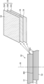
- FIG. 1 is a schematic diagram showing a configuration of a friction stir spot welding apparatus including a friction stir spot welding tool according to an embodiment of the present disclosure.
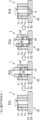
- FIG. 2 is a diagram showing the configurations of a first member and a second member to be friction stir spot welded.
- FIG. 3 is a diagram showing a joining procedure by a pin-first process using a friction stir spot welding tool.
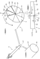
- FIG. 4 is a perspective view and a side view showing the shape of a pin and its tip surface of a friction stir spot welding tool according to an embodiment of the present disclosure, together with a comparative example.
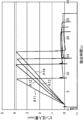
- FIG. 5 is a graph showing the relationship between the amount of press-in of the pin into the test piece and the joining time for the examples and the comparative examples.
- FIG. 1 is a schematic diagram showing a configuration of a friction stir spot welding apparatus including a friction stir spot welding tool according to an embodiment of the present disclosure.
- FIG. 2 is a diagram showing the configurations of a first member and a second member to be friction stir
- FIG. 6 is a graph showing the relationship between the amount of pressurization and the joining time when the pin of the embodiment is pressed into the test piece by changing the pressure applied thereto.
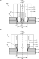
- FIG. 7A is a diagram showing the behavior of the stirred material in a shoulder-first process
- FIG. 7B is a diagram showing the behavior of the stirred material in a pin-first process.
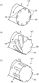
- 8A to 8C are perspective views showing other examples of the shape of the pin tip of the friction stir spot welding tool.
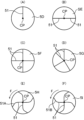
- 9A to 9F are plan views showing modified examples of the shape of the tip surface of the pin shown in FIG.
- a friction stir spot welding device equipped with a friction stir spot welding tool can be used to manufacture various joined bodies formed by overlapping and spot-joining two or more structural materials, such as plates, frames, exterior materials, or columnar materials made of metal, resin, or thermoplastic resin molded bodies mixed with fibrous materials.
- the joints manufactured become components of structures such as aircraft, railway vehicles, or automobiles.
- Fig. 1 is a schematic diagram showing the configuration of a friction stir spot welding apparatus M according to an embodiment of the present disclosure.
- the friction stir spot welding apparatus M includes a double-action friction stir spot welding tool 1, a tool drive unit 2 that drives the tool 1 to rotate and elevate, and a controller 20 that controls the operation of each part of the friction stir spot welding apparatus M.
- the tool 1 is supported by various tool fixing parts.
- the tool fixing part is the tip of an articulated robot.
- a backup 15 is arranged facing the lower end surface of the tool 1.
- the object to be joined 3 is arranged between the tool 1 and the backup 15.
- the object to be joined 3 is composed of at least two members overlapped.
- Figure 1 shows an example in which an overlapping portion 30, in which a part of a first member 31 made of a flat plate and a part of a second member 32 also made of a flat plate overlap in the vertical direction, is arranged between the tool 1 and the backup 15 as the object to be joined 3.
- the tool 1 includes a pin 11, a shoulder 12, a clamp 13, and a spring 14.
- the pin 11 is a cylindrical member and is arranged so that its axis extends in the vertical direction.
- the pin 11 can rotate around the axis R, and can move forward and backward in the vertical direction along the rotation axis R.
- the rotation axis R is aligned with the point joining position W at the overlapping portion 30.
- the shoulder 12 is a cylindrical member having a hollow portion through which the pin 11 is inserted.
- the axis of the shoulder 12 is coaxial with the axis of the pin 11, i.e., the rotation axis R.
- the shoulder 12 can rotate around the rotation axis R, and can move up and down along the rotation axis R.
- the tool 1 of this embodiment is a double-acting tool in which the pin 11 and the shoulder 12 move independently in the axial direction.
- the shoulder 12 and the pin 11 inserted in the hollow portion can move relatively in the direction of the rotation axis R while both rotating around the axis of the rotation axis R.
- the pin 11 and the shoulder 12 can not only rise and fall simultaneously along the rotation axis R, but can also move independently, with one descending and the other ascending.
- the clamp 13 is a cylindrical member with a hollow portion into which the shoulder 12 is inserted.
- the axis of the clamp 13 is also coaxial with the rotation axis R.
- the clamp 13 does not rotate around its axis, but moves up and down along the rotation axis R, that is, moves forward and backward.
- the clamp 13 serves to surround the outer periphery of the pin 11 or shoulder 12 when they perform friction stirring.
- the enclosure with the clamp 13 prevents the friction stirring material from scattering, and allows the friction stirring point joint to be finished smoothly.
- the spring 14 is attached to the upper end side of the clamp 13 and biases the clamp 13 downward toward the overlapping portion 30.
- the clamp 13 is attached to the tool fixing portion via the spring 14.
- the backup 15 has a flat surface that abuts against the underside of the overlapping portion 30 to be joined.
- the backup 15 is a backing member that supports the overlapping portion 30 when the pin 11 or shoulder 12 is pressed into the overlapping portion 30.
- the clamp 13 biased by the spring 14 presses the overlapping portion 30 against the backup 15.
- the tool driving unit 2 includes a rotation driving unit 21, a pin driving unit 22, a shoulder driving unit 23, and a clamp driving unit 24.
- the rotation driving unit 21 includes a motor, a driving gear, etc., and drives the pin 11 and the shoulder 12 to rotate around the rotation axis R.
- the pin driving unit 22 is a mechanism that moves the pin 11 back and forth along the rotation axis R.
- the pin driving unit 22 drives the pin 11 so as to press the pin 11 into the overlapping portion 30 and to retract the pin 11 from the overlapping portion 30.
- the shoulder driving unit 23 is a mechanism that moves the shoulder 12 back and forth along the rotation axis R, and presses the shoulder 12 into the overlapping portion 30 and to retract the shoulder 12 from the overlapping portion 30.
- the clamp driving unit 24 is a mechanism that moves the clamp 13 back and forth along the rotation axis R.
- the clamp driving unit 24 moves the clamp 13 toward the overlapping portion 30 and presses the overlapping portion 30 against the backup 15. At this time, the biasing force of the spring 14 acts.
- the controller 20 is comprised of a microcomputer or the like, and controls the operation of the tool driving unit 2 by executing a predetermined control program. Specifically, the controller 20 controls the rotation driving unit 21 to cause the pin 11 and shoulder 12 to perform the required rotational operation. The controller 20 also controls the pin driving unit 22, shoulder driving unit 23, and clamp driving unit 24 to cause the pin 11, shoulder 12, and clamp 13 to perform the required forward and backward movement operation.
- FIG. 2 is a diagram showing the configuration of a first member 31 and a second member 32 to be friction stir spot welded.
- an overlapping portion 30 is shown in which a part of a plate-shaped first member 31 and a part of a plate-shaped second member 32 are overlapped vertically.
- the overlapping portion 30 may be an overlapping portion between a plate and a frame or a columnar material, or an overlapping portion between frames.
- the overlapping portion 30 has a mating surface BD where a joining surface 31A on the lower surface of the first member 31 and a joining surface 32A on the upper surface of the second member 32 are in direct contact with each other.
- One or more other plates may be interposed between the first member 31 and the second member 32.
- FIG. 2 an example is shown in which a molded body made of multiple layers of prepregs impregnated with a thermoplastic resin in an array of continuous fibers is used as the first member 31 and the second member 32.
- FIG. 2 shows a part of the sheet stack 33 constituting the first member 31.
- the sheet stack 33 includes a first sheet layer 33A, a second sheet layer 33B, and a third sheet layer 33C, each of which is made of a sheet impregnated with a thermoplastic resin in an array of continuous fibers.
- the first sheet layer 33A is a sheet with a thickness of about 0.1 mm to 0.5 mm, in which a large number of continuous fibers 34 are arranged in a predetermined arrangement direction and the array is impregnated with a thermoplastic resin to integrate it.
- the second sheet layer 33B and the third sheet layer 33C are also sheets similar to those described above, but the arrangement directions of the continuous fibers 34 are mutually different.
- the second member 32 is also a plate made of a multi-layer laminate of sheets similar to the first member 31.
- the continuous fibers 34 are cut by pressing the tool 1 in, while the thermoplastic resin of the impregnating material is friction stirred.
- the prepreg molded body is an example of a constituent material of the first member 31 and the second member 32.
- the overlapping portion 30 may be formed using two or more metal plates such as aluminum or steel.
- the first member 31 on the side where the tool 1 is pressed in first is an aluminum alloy, and the second member 32 is a high tensile steel.
- the method of using the friction stir spot welding apparatus M is roughly classified into a pin-first process in which the pin 11 of the tool 1 is first pressed into the overlapping portion 30 of the workpieces 3, and a shoulder-first process in which the shoulder 12 is first pressed into the overlapping portion 30.
- the controller 20 drives the tool 1 to operate in the pin-first process.
- FIG. 3 shows processes P11 to P14 of the friction stir spot welding method using the pin-first process.
- the process for friction stir spot welding of the overlapping portion 30 of the first member 31 and the second member 32 is shown in a simplified manner.
- Process P11 shows the preheating step of the overlapping portion 30. With the lower end of the tool 1 in contact with the surface of the first member 31, the pin 11 and shoulder 12 are rotated around the axis at a predetermined speed.
- Process P12 shows the step of pressing in the pin 11. As shown by the white arrow in the figure, the pin 11 is rotated around its axis while being lowered and pressed into the overlapping portion 30, while the shoulder 12 is withdrawn upward. This action agitates the material in the pressing area of the pin 11. In addition, the overflow material OF that overflows from the overlapping portion 30 due to the pressing is released into the annular area between the pin 11 and the clamp 13 that is created by the withdrawal of the shoulder 12 (see arrow a1).
- Process P13 shows the backfilling process of the overflow material OF.
- the pin 11 is raised and retracted, while the shoulder 12 is lowered.
- the shoulder 12 is lowered.
- the overflow material OF that has escaped to the annular region is backfilled into the press-fit region of the pin 11.
- Process P14 shows a smoothing process. With the lower end faces of the pin 11 and shoulder 12 returned to the same height position as the surface of the first member 31, both are rotated to smooth the spot-joined portion. Note that if the first member 31 is made of thermoplastic resin, the pin 11 and shoulder 12 may not be rotated in process P14, and the spot-joined portion may simply be pressed. Through the above process, the stirred joint 4a is formed, and the first member 31 and the second member 32 are spot-joined at the overlapping portion 30.
- FIG. 4 is a perspective view and a side view showing the shape of the pin 11 and its tip 11T of the friction stir spot welding tool 1 according to the embodiment of the present disclosure, together with a comparative example.
- the tip 11T of the pin 11 has a shape having a circular tip surface 50 made of a flat surface, as shown in the ⁇ Comparative Example> section.
- the tip surface 50 is a flat surface without any steps or the like.
- thermoplastic resin prepreg reinforced with continuous fibers 34 such as a sheet stack 33 made of thermoplastic CFRP, as shown in FIG. 2, and at least the first member 31 is composed of this type of first member 31.
- the pin 11 is pressed in while cutting the continuous fibers 34 during friction stirring.
- a large pressure force needs to be applied to the tool 1.
- the tip portion 11T of the pin 11 has a tip surface 5 shape that can suppress the joining pressure force.
- the tip surface 5 is circular when viewed in the axial direction, as in the conventional case, but the tip surface 5 is provided with a step-shaped portion 51 that forms a step in the rotational direction F of the pin 11.
- the step of the step-shaped portion 51 is a radial step that extends radially from the center point CP of the circular tip surface 5 to the outer periphery of the circle.
- a plurality of step-shaped portions 51 are arranged in the circumferential direction of the tip surface 5.
- Figure 4 shows an example in which eight radial steps are arranged at equal intervals in the circumferential direction of the tip surface 5.
- the step-shaped portion 51 is shallowest at the center point C of the tip surface 5 and deepest at the outer periphery of the tip surface 5.
- the step-shaped portion 51 has a shape in which the step height h gradually increases from the center point C toward the radial outside of the tip surface 5.
- eight fan-shaped surfaces 52 of the same size are lined up in the circumferential direction on the tip surface 5. These fan-shaped surfaces 52 are surfaces with an inclination that corresponds to the step height h of the step-shaped portion 51.
- the sector surface 52 has an inclination such that the front end 521 in the rotation direction F of the pin 11 is higher and the rear end 522 is lower.
- the "high" front end 521 means that, assuming that the tip surface 5 is the lower end surface of the pin 11, the front end 521 protrudes downward more than the rear end 522.
- the line Ho added to the ⁇ side view> is a horizontal line perpendicular to the axis of the pin 11.
- the sector surface 52 has an inclination determined by the step height h with respect to this line Ho.
- the step height h is maximum at the position of the outer periphery of the tip surface 5.
- the height of the front end 521 and the height of the center point CP are the same height.
- the height of the rear end 522 is the same height as the center point CP at the position of the center point CP, but is lower by the maximum step height h at the position of the outer periphery of the tip surface 5.
- the center point CP of the tip surface 5 does not protrude downward.
- the flatness of the tip surface 5 is ensured from a macroscopic perspective. This is because, as described above, in process P14 in FIG. 3, there is a step in which the tip surface 5 of the pin 11 is pressed against the surface of the stir welded portion 4 to be finished, and it is taken into consideration that the shape of the tip surface 5 is transferred to the surface of the stir welded portion 4 in this step.
- the stepped portion 51 has a stepped surface based on the difference in height between the front end 521 and rear end 522 of a pair of circumferentially adjacent fan surfaces 52. This stepped surface extends in a direction perpendicular to the direction of rotation F.
- the stepped surface and the right-angled edge of the front end 521 form a blade shape that cuts the objects to be joined. Such a blade improves the agitation of the objects to be joined and the ability to push the agitation material radially outward, and also contributes to cutting the continuous fibers 34 described above.
- the step surface of the step-shaped portion 51 may be a vertical surface parallel to the axis Zo of the pin 11, or may be a surface having an inclination angle ⁇ with respect to the axis Zo as shown in FIG. 4.
- the step surface of the step-shaped portion 51 in the illustrated example is a surface that intersects at a right angle with a sector surface 52 that is inclined with respect to the line Ho.
- the inclination angle ⁇ can be selected, for example, from the range of 2 degrees to 7 degrees.
- the pin 11 was press-fitted into the overlapping portion 30 by using the tools 1 of the example and the comparative example, with the target press-fit value of 3.87 mm.
- the pin 11 was press-fitted to achieve the target press-fit value.
- Comparative Example 9 [kN] It was confirmed that the tool 1 of the embodiment can perform friction stir spot welding of the overlapping portion 30 with a pressure force significantly lower than that of the comparative example.
- ⁇ Test 2> A test was conducted in which the pin 11 was pressed into the same metal sample with the same pressing force using a tool 1 having the same tip surface 5 of the example and a tool 1 having the tip surface 50 of the comparative example as in Test 1.
- a 1 mm thick sample of A7075 aluminum alloy specified in JIS-H-4040 that had been subjected to T6 treatment was used as the metal sample.
- the target value for pressing the pin 11 into the sample was set to 0.5 mm, and the pressing force was set to 5.5 kN, and the pin 11 of the tool 1 of the example and the comparative example was pressed into the metal sample.
- Figure 5 is a graph showing the relationship between the amount of pressing (mm) of the pin 11 into the metal sample and the joining time (seconds) for the embodiment and the comparative example.
- Characteristic A1 shows the pressing behavior of the pin 11 by the tool 1 of the embodiment. It can be seen that the pressing of the pin 11 to the target value was completed about 2.5 seconds after the start of pressing the pin 11 into the metal sample.
- characteristic B1 shows the pressing behavior of the pin 11 by the tool 1 of the comparative example. As a result, the pin 11 could not be pressed to achieve the pressing target value with the set pressure of 5.5 kN.
- Characteristic B2 shows the pressing behavior when the pin 11 was pressed into the metal sample by applying a pressing force of 8.7 kN, which can be set by the test device used to execute Test 2, to the tool 1 of the comparative example.
- a pressing force of 8.7 kN which can be set by the test device used to execute Test 2
- characteristic B2 shows the pressing behavior when the pin 11 was pressed into the metal sample by applying a pressing force of 8.7 kN, which can be set by the test device used to execute Test 2, to the tool 1 of the comparative example.
- ⁇ Test 3> The relationship between the pin press-in amount and joining time was investigated using overlapping portion 30 formed from the thermoplastic CFRP resin sheet used in Test 1 and tool 1 having tip surface 5 of the example. In Test 1, it was confirmed that the press-in target value of 3.87 mm could be achieved with a pressure of 4 kN for tool 1, but an investigation was conducted to see whether press-in was possible with a lower pressure.
- Figure 6 is a graph showing the relationship between the amount of pin press-in (mm) and the joining time (seconds) when the pressure applied to tool 1 of the embodiment is changed and the pin is pressed into overlapping portion 30.
- Characteristics A11, A12, A13, and A14 shown in the graph show the press-in behavior when the pressure is 4 kN, 3.5 kN, 3 kN, and 2 kN, respectively.
- the target press-in value can be achieved even when the pressure is reduced to 2 kN by reducing the press-in speed of pin 11 and thereby lengthening the joining time.
- the target press-in value could not be achieved with a pressure of 4 kN, no matter how much the press-in speed of pin 11 was reduced.
- the step-shaped portion 51 contributes to reducing the joining pressure when joining objects by pressing the pin 11 in the pin-first process.
- the material directly below the pin 11 is stirred and fluidized, and is pushed out into the annular space created by the retraction of the shoulder on the outer periphery of the pin 11.
- the step-shaped portion 51 on the tip surface 5 of the pin 11 forms a step in the rotation direction F of the pin 11. Therefore, when the pin 11 is pressed into the objects 3 to be joined while rotating around its axis, the step-shaped portion 51 actively cuts the material directly below the pin 11. Even if the objects 3 to be joined are a sheet stack 33 as shown in FIG. 2, the step-shaped portion 51 acts as a blade to cut the continuous fibers 34, so the joining pressure can be reduced.
- Figure 7 (A) shows the behavior of the stirring material in the shoulder-first process
- Figure 7 (B) shows the behavior of the stirring material in the pin-first process.
- the overflow material OF escapes into the space in the shoulder 120 created by the rise of the pin 110, as shown by arrow a3.
- the overflow material OF will have no escape route, and as shown by arrow a4, a flow in which the material flows out radially outward of the shoulder 120 below the clamp 130 may occur.
- dents are likely to occur in the friction stir spot weld.
- the overflow material OF is originally set to escape radially outward of the pin 11. Therefore, even if the application of the stepped portion 51 increases the flow of the stirring material, the overflowing material OF easily returns to the stirring area, and no dents are formed in the friction stir spot weld.
- the pin-first process produces a larger volume of overflow material OF.
- the overflow material OF when the pin-first process is used is 1.8 times that of the shoulder-first process.
- FIG. 8(A) to (C) are perspective views showing other examples of the shape of the tip portion 11T of the pin 11 of the friction stir spot welding tool 1.
- Fig. 8(A) to (C) examples are shown in which the steps of the step-shaped portion are steps formed by cutting out parts of the outer circumferential edges of the pin tip surfaces 5A, 5B, and 5C. These steps are formed by groove-shaped cutouts.
- the tip surface 5A of the tip portion 11T shown in FIG. 8(A) has a plurality of oblique grooves 53 formed thereon.
- the oblique grooves 53 are recessed grooves formed in the tip surface 5A, and extend linearly from the outer periphery of the tip surface 5A to the radially inward direction of the tip surface 5A.
- the oblique grooves 53 are grooves that are inclined toward the outer periphery with respect to an imaginary line corresponding to the diameter of the circular tip surface 5A.
- the inclination is an inclination that directs the oblique grooves 53 in a direction that follows the rotation direction F of the pin 11.
- FIG. 8(A) shows an example in which eight short oblique grooves 53 are arranged at equal intervals along the outer periphery of the tip surface 5A.
- the length, radius, depth, arrangement pitch, inclination, etc. of the oblique grooves 53 can be changed as appropriate.
- the tip portion 11T shown in FIG. 8(B) has multiple spiral grooves 54 formed starting from the tip surface 5B and extending in the axial direction of the pin 11.
- the spiral grooves 54 are recessed grooves formed in the side peripheral surface of the tip portion 11T, and extend spirally from the outer periphery of the tip surface 5B upstream in the rotation direction F.
- a step shape is formed near the outer periphery of the tip surface 5B by cutting out the spiral grooves 54 radially inward.
- the spiral grooves 54 in FIG. 8(B) are just an example, and the length, radius, depth, arrangement pitch, and helical angle of the spiral grooves 54 can be changed as appropriate.
- the tip portion 11T shown in FIG. 8(C) has an axial groove 55 formed therein, which starts from the tip surface 5C and extends linearly in the axial direction of the pin 11.
- the axial groove 55 is a recessed groove formed in the side peripheral surface of the tip portion 11T, and extends a predetermined length in the axial direction of the pin 11 from the outer periphery of the tip surface 5B.
- both the clockwise and counterclockwise directions can be set as the rotation direction FA.
- a step shape is formed near the outer periphery of the tip surface 5C by cutting out the axial groove 55 radially inward.
- the axial groove 55 in FIG. 8(C) is an example, and the length, radius, depth, arrangement pitch, etc. of the axial groove 55 can be changed as appropriate.
- a step can be formed by cutting out a portion of the outer edge of the pin tip surface. This step can also promote the cutting out of the material directly below the pin 11 and the extrusion of the material into the shoulder evacuation space, reducing the joining pressure of the tool 1.
- Figures 9(A) to (F) show various modified examples of forming the step-shaped portion 51 shown in Figure 4 on the tip surface of the pin 11.
- Figure 9(A) shows a tip surface 5D that has only one step-shaped portion 51.
- the step-shaped portion 51 extends linearly from the center point C toward the outer periphery of the tip surface 5D, and has a shape in which the step height gradually increases toward the radially outward direction.
- Figure 9(B) shows a tip surface 5E having two step-shaped portions 51.
- the two step-shaped portions 51 are arranged in a straight line on either side of the center point C.
- the tip surface 5E has two semicircular surfaces. These semicircular surfaces are surfaces that have an inclination according to the step of the step-shaped portion 51.
- Figure 9(C) shows a tip surface 5F having four step-shaped portions 51.
- the four step-shaped portions 51 are arranged at equal intervals of 90 degrees in the circumferential direction.
- the tip surface 5F has four fan surfaces of the same size arranged in the circumferential direction.
- Figure 9(D) shows a tip surface 5G in which the four step-shaped portions 51 are arranged at random intervals in the circumferential direction. As in the example of Figure 9(D), the step-shaped portions 51 do not have to be arranged at equal intervals in the circumferential direction.
- FIG. 9(E) shows a tip surface 5H having four step-shaped portions 51 each having a curved portion 51A.
- the step-shaped portion 51 extends linearly in the radial direction, but the tip surface 5H may have a curved portion 51A as in the example of FIG. 9(E).
- the curved portion 51A is a portion of the step-shaped portion 51 near the outer periphery of the tip surface 5H that is curved to follow the rotation direction F.
- FIG. 9(F) also shows a tip surface 5I having four step-shaped portions 51 each having a curved portion 51B.
- the curved portion 51B here is a portion of the step-shaped portion 51 near the outer periphery of the tip surface 5H that is curved in the opposite direction to the rotation direction F.
- the friction stir spot welding tool comprises a cylindrical pin that rotates about an axis, a shoulder having a hollow portion through which the pin is inserted, and a drive unit that drives the pin to rotate while pressing it into the workpieces to be joined and drives the shoulder to retract from the workpieces to be joined, and at least a portion of the circular tip surface of the pin is provided with a step-shaped portion that forms a step in the direction of rotation of the pin.
- the step-shaped portion when the workpieces are joined by pressing the pin, the step-shaped portion contributes to reducing the joining pressure. That is, in the pin-first process in which the pin is pressed in while the shoulder is retracted, the material directly below the pin is pushed out into the shoulder retraction space present on the outer periphery of the pin.
- the step-shaped portion forms a step in the rotation direction of the pin. Therefore, when the pin is pressed into the workpieces while rotating around the axis, the step-shaped portion actively pushes out the material directly below the pin into the shoulder retraction space while scraping it. This makes it easier to stir the material directly below the pin and to flow the stirred material radially outward from the pin.
- the pin pressure on the workpieces during friction stir spot welding that is, the joining pressure that must be applied to the tool
- the reaction force can also be suppressed by reducing the joining pressure, it becomes possible to mount a friction stir spot welding tool on a small robot or a small dedicated device. This makes it possible to avoid the need for larger equipment, including friction stir spot welding tools, and increased costs.
- the friction stir spot welding tool according to the second aspect is the tool according to the first aspect, in which the step of the stepped portion is a radial step extending radially from the center point of the tip surface to the outer periphery.
- the step is a radial step, so that the material can be efficiently pushed out toward the outer periphery of the pin when stirring by pressing the pin.
- the friction stir spot welding tool of the third aspect is the tool of the second aspect, in which the radial steps are arranged in multiple circumferential directions on the tip surface of the pin.
- multiple radial steps are arranged in the circumferential direction, which makes it possible to increase the force pushing the material outward from the pin, and to reduce the pressure applied by the pin.
- the friction stir spot welding tool of the fourth aspect is the tool of the third aspect, in which the multiple radial steps are evenly spaced in the circumferential direction of the tip surface.
- multiple radial steps are arranged at equal intervals, allowing for a balanced process of cutting away material directly below the pin and pushing that material outward toward the outer periphery of the pin.
- the friction stir spot welding tool according to the fifth aspect is a tool according to the first to fourth aspects, in which the maximum height difference of the step of the step-shaped portion is set in the range of 1% to 10% of the diameter of the pin.
- the step height of the stepped portion can be optimized.
- the friction stir spot welding tool according to the sixth aspect is the tool according to the first aspect, in which the step of the step-shaped portion is a step formed by cutting out a part of the outer periphery of the tip surface.
- the sixth aspect even if there is a step due to a partial cutout on the outer periphery, it is possible to promote the cutting of the material directly below the pin and the extrusion of the material into the shoulder evacuation space, thereby reducing the joining pressure of the tool.
Landscapes
- Engineering & Computer Science (AREA)
- Mechanical Engineering (AREA)
- Pressure Welding/Diffusion-Bonding (AREA)
Priority Applications (1)
| Application Number | Priority Date | Filing Date | Title |
|---|---|---|---|
| EP24810677.5A EP4706862A1 (en) | 2023-05-22 | 2024-03-12 | Friction stir spot welding tool |
Applications Claiming Priority (2)
| Application Number | Priority Date | Filing Date | Title |
|---|---|---|---|
| JP2023084103A JP2024167781A (ja) | 2023-05-22 | 2023-05-22 | 摩擦攪拌点接合用ツール |
| JP2023-084103 | 2023-05-22 |
Publications (1)
| Publication Number | Publication Date |
|---|---|
| WO2024241669A1 true WO2024241669A1 (ja) | 2024-11-28 |
Family
ID=93589312
Family Applications (1)
| Application Number | Title | Priority Date | Filing Date |
|---|---|---|---|
| PCT/JP2024/009545 Ceased WO2024241669A1 (ja) | 2023-05-22 | 2024-03-12 | 摩擦攪拌点接合用ツール |
Country Status (3)
| Country | Link |
|---|---|
| EP (1) | EP4706862A1 (cg-RX-API-DMAC10.html) |
| JP (1) | JP2024167781A (cg-RX-API-DMAC10.html) |
| WO (1) | WO2024241669A1 (cg-RX-API-DMAC10.html) |
Citations (6)
| Publication number | Priority date | Publication date | Assignee | Title |
|---|---|---|---|---|
| JP2015123488A (ja) * | 2013-12-27 | 2015-07-06 | 株式会社Uacj | 金属箔重ね点接合方法 |
| JP2015186869A (ja) | 2014-03-27 | 2015-10-29 | トヨタ自動車株式会社 | 接合方法 |
| JP2017200702A (ja) * | 2016-05-06 | 2017-11-09 | 株式会社Uacj | 摩擦撹拌接合用工具および摩擦撹拌接合方法 |
| WO2020138326A1 (ja) * | 2018-12-26 | 2020-07-02 | 川崎重工業株式会社 | 摩擦攪拌点接合装置及びその運転方法 |
| JP2021164943A (ja) * | 2020-04-08 | 2021-10-14 | Jfeスチール株式会社 | アルミニウム合金板と鋼板の摩擦撹拌接合方法 |
| WO2023038117A1 (ja) * | 2021-09-10 | 2023-03-16 | 株式会社 東芝 | 摩擦攪拌接合用ツール部材、摩擦攪拌接合装置、および摩擦攪拌接合方法 |
-
2023
- 2023-05-22 JP JP2023084103A patent/JP2024167781A/ja active Pending
-
2024
- 2024-03-12 EP EP24810677.5A patent/EP4706862A1/en active Pending
- 2024-03-12 WO PCT/JP2024/009545 patent/WO2024241669A1/ja not_active Ceased
Patent Citations (6)
| Publication number | Priority date | Publication date | Assignee | Title |
|---|---|---|---|---|
| JP2015123488A (ja) * | 2013-12-27 | 2015-07-06 | 株式会社Uacj | 金属箔重ね点接合方法 |
| JP2015186869A (ja) | 2014-03-27 | 2015-10-29 | トヨタ自動車株式会社 | 接合方法 |
| JP2017200702A (ja) * | 2016-05-06 | 2017-11-09 | 株式会社Uacj | 摩擦撹拌接合用工具および摩擦撹拌接合方法 |
| WO2020138326A1 (ja) * | 2018-12-26 | 2020-07-02 | 川崎重工業株式会社 | 摩擦攪拌点接合装置及びその運転方法 |
| JP2021164943A (ja) * | 2020-04-08 | 2021-10-14 | Jfeスチール株式会社 | アルミニウム合金板と鋼板の摩擦撹拌接合方法 |
| WO2023038117A1 (ja) * | 2021-09-10 | 2023-03-16 | 株式会社 東芝 | 摩擦攪拌接合用ツール部材、摩擦攪拌接合装置、および摩擦攪拌接合方法 |
Also Published As
| Publication number | Publication date |
|---|---|
| EP4706862A1 (en) | 2026-03-11 |
| JP2024167781A (ja) | 2024-12-04 |
Similar Documents
| Publication | Publication Date | Title |
|---|---|---|
| US11534981B2 (en) | Friction stir spot welding apparatus and friction stir spot welding method | |
| JP7684900B2 (ja) | 摩擦攪拌点接合装置、摩擦攪拌点接合された被接合物、及びショルダ部材 | |
| CN109070264B (zh) | 点接合装置、点接合方法及接头结构 | |
| JP7489457B2 (ja) | 摩擦攪拌点接合装置及び継手構造 | |
| EP3903986B1 (en) | Friction stir spot welding device and method for operating same | |
| JP2003320465A (ja) | テーパー摩擦撹拌溶接工具 | |
| WO2006081819A1 (en) | A device for friction stir welding and a method of welding | |
| US20230241708A1 (en) | Friction stir spot welding method and welded assembly using same | |
| EP1769876B1 (en) | Friction stir spot welding method and apparatus with an holding member having a restriction portion | |
| JP2024167781A (ja) | 摩擦攪拌点接合用ツール | |
| JP3452044B2 (ja) | 摩擦攪拌ツールおよびこれを用いた接合方法ならびに鋳物表面の微細空隙除去方法 | |
| US12485622B2 (en) | Joint structure and joining method | |
| KR102747977B1 (ko) | 마찰교반 점접합 장치 및 그 운전 방법 | |
| JP2023089462A (ja) | 異種金属の接合方法、接合体、および接合装置 | |
| JP2002292480A (ja) | 摩擦撹拌を用いた接合方法及び装置 | |
| US20240181558A1 (en) | Mechanical metal joint for vehicle component | |
| JP2002292479A (ja) | 摩擦撹拌を用いた接合装置 | |
| JP4755887B2 (ja) | 材料の接合方法 | |
| WO2025253900A1 (ja) | 摩擦攪拌点接合装置および摩擦攪拌点接合方法 | |
| JP5128927B2 (ja) | チップ成形機 | |
| JP7573471B2 (ja) | 接合方法、接合体及び接合装置 | |
| JP2018183811A (ja) | 摩擦撹拌点接合装置の裏当て部材、摩擦撹拌点接合装置、摩擦撹拌点接合方法及び継手構造 | |
| JP2008055430A (ja) | 摩擦点接合装置 | |
| WO2025004829A1 (ja) | 摩擦攪拌点接合方法および摩擦攪拌点接合装置 | |
| JP6766377B2 (ja) | 接合方法 |
Legal Events
| Date | Code | Title | Description |
|---|---|---|---|
| 121 | Ep: the epo has been informed by wipo that ep was designated in this application |
Ref document number: 24810677 Country of ref document: EP Kind code of ref document: A1 |
|
| WWE | Wipo information: entry into national phase |
Ref document number: 2024810677 Country of ref document: EP |
|
| ENP | Entry into the national phase |
Ref document number: 2024810677 Country of ref document: EP Effective date: 20251204 |
|
| ENP | Entry into the national phase |
Ref document number: 2024810677 Country of ref document: EP Effective date: 20251204 |
|
| ENP | Entry into the national phase |
Ref document number: 2024810677 Country of ref document: EP Effective date: 20251204 |
|
| NENP | Non-entry into the national phase |
Ref country code: DE |
|
| ENP | Entry into the national phase |
Ref document number: 2024810677 Country of ref document: EP Effective date: 20251204 |
|
| ENP | Entry into the national phase |
Ref document number: 2024810677 Country of ref document: EP Effective date: 20251204 |
|
| ENP | Entry into the national phase |
Ref document number: 2024810677 Country of ref document: EP Effective date: 20251204 |
|
| ENP | Entry into the national phase |
Ref document number: 2024810677 Country of ref document: EP Effective date: 20251204 |
|
| ENP | Entry into the national phase |
Ref document number: 2024810677 Country of ref document: EP Effective date: 20251204 |
|
| ENP | Entry into the national phase |
Ref document number: 2024810677 Country of ref document: EP Effective date: 20251204 |
|
| WWP | Wipo information: published in national office |
Ref document number: 2024810677 Country of ref document: EP |