WO2024241439A1 - 画像表示システムおよび画像表示方法 - Google Patents
画像表示システムおよび画像表示方法 Download PDFInfo
- Publication number
- WO2024241439A1 WO2024241439A1 PCT/JP2023/018992 JP2023018992W WO2024241439A1 WO 2024241439 A1 WO2024241439 A1 WO 2024241439A1 JP 2023018992 W JP2023018992 W JP 2023018992W WO 2024241439 A1 WO2024241439 A1 WO 2024241439A1
- Authority
- WO
- WIPO (PCT)
- Prior art keywords
- image
- imaging
- imaging conditions
- conditions
- lighting
- Prior art date
- Legal status (The legal status is an assumption and is not a legal conclusion. Google has not performed a legal analysis and makes no representation as to the accuracy of the status listed.)
- Ceased
Links
Images




Classifications
-
- H—ELECTRICITY
- H04—ELECTRIC COMMUNICATION TECHNIQUE
- H04N—PICTORIAL COMMUNICATION, e.g. TELEVISION
- H04N23/00—Cameras or camera modules comprising electronic image sensors; Control thereof
- H04N23/60—Control of cameras or camera modules
-
- H—ELECTRICITY
- H04—ELECTRIC COMMUNICATION TECHNIQUE
- H04N—PICTORIAL COMMUNICATION, e.g. TELEVISION
- H04N23/00—Cameras or camera modules comprising electronic image sensors; Control thereof
- H04N23/60—Control of cameras or camera modules
- H04N23/62—Control of parameters via user interfaces
-
- H—ELECTRICITY
- H04—ELECTRIC COMMUNICATION TECHNIQUE
- H04N—PICTORIAL COMMUNICATION, e.g. TELEVISION
- H04N23/00—Cameras or camera modules comprising electronic image sensors; Control thereof
- H04N23/60—Control of cameras or camera modules
- H04N23/63—Control of cameras or camera modules by using electronic viewfinders
-
- H—ELECTRICITY
- H04—ELECTRIC COMMUNICATION TECHNIQUE
- H04N—PICTORIAL COMMUNICATION, e.g. TELEVISION
- H04N23/00—Cameras or camera modules comprising electronic image sensors; Control thereof
- H04N23/60—Control of cameras or camera modules
- H04N23/63—Control of cameras or camera modules by using electronic viewfinders
- H04N23/631—Graphical user interfaces [GUI] specially adapted for controlling image capture or setting capture parameters
- H04N23/632—Graphical user interfaces [GUI] specially adapted for controlling image capture or setting capture parameters for displaying or modifying preview images prior to image capturing, e.g. variety of image resolutions or capturing parameters
-
- H—ELECTRICITY
- H04—ELECTRIC COMMUNICATION TECHNIQUE
- H04N—PICTORIAL COMMUNICATION, e.g. TELEVISION
- H04N23/00—Cameras or camera modules comprising electronic image sensors; Control thereof
- H04N23/60—Control of cameras or camera modules
- H04N23/63—Control of cameras or camera modules by using electronic viewfinders
- H04N23/633—Control of cameras or camera modules by using electronic viewfinders for displaying additional information relating to control or operation of the camera
-
- H—ELECTRICITY
- H04—ELECTRIC COMMUNICATION TECHNIQUE
- H04N—PICTORIAL COMMUNICATION, e.g. TELEVISION
- H04N23/00—Cameras or camera modules comprising electronic image sensors; Control thereof
- H04N23/60—Control of cameras or camera modules
- H04N23/64—Computer-aided capture of images, e.g. transfer from script file into camera, check of taken image quality, advice or proposal for image composition or decision on when to take image
-
- H—ELECTRICITY
- H04—ELECTRIC COMMUNICATION TECHNIQUE
- H04N—PICTORIAL COMMUNICATION, e.g. TELEVISION
- H04N23/00—Cameras or camera modules comprising electronic image sensors; Control thereof
- H04N23/60—Control of cameras or camera modules
- H04N23/667—Camera operation mode switching, e.g. between still and video, sport and normal or high- and low-resolution modes
-
- H—ELECTRICITY
- H04—ELECTRIC COMMUNICATION TECHNIQUE
- H04N—PICTORIAL COMMUNICATION, e.g. TELEVISION
- H04N23/00—Cameras or camera modules comprising electronic image sensors; Control thereof
- H04N23/70—Circuitry for compensating brightness variation in the scene
- H04N23/71—Circuitry for evaluating the brightness variation
-
- H—ELECTRICITY
- H04—ELECTRIC COMMUNICATION TECHNIQUE
- H04N—PICTORIAL COMMUNICATION, e.g. TELEVISION
- H04N23/00—Cameras or camera modules comprising electronic image sensors; Control thereof
- H04N23/70—Circuitry for compensating brightness variation in the scene
- H04N23/73—Circuitry for compensating brightness variation in the scene by influencing the exposure time
-
- H—ELECTRICITY
- H04—ELECTRIC COMMUNICATION TECHNIQUE
- H04N—PICTORIAL COMMUNICATION, e.g. TELEVISION
- H04N23/00—Cameras or camera modules comprising electronic image sensors; Control thereof
- H04N23/70—Circuitry for compensating brightness variation in the scene
- H04N23/74—Circuitry for compensating brightness variation in the scene by influencing the scene brightness using illuminating means
-
- H—ELECTRICITY
- H04—ELECTRIC COMMUNICATION TECHNIQUE
- H04N—PICTORIAL COMMUNICATION, e.g. TELEVISION
- H04N23/00—Cameras or camera modules comprising electronic image sensors; Control thereof
- H04N23/80—Camera processing pipelines; Components thereof
-
- H—ELECTRICITY
- H04—ELECTRIC COMMUNICATION TECHNIQUE
- H04N—PICTORIAL COMMUNICATION, e.g. TELEVISION
- H04N23/00—Cameras or camera modules comprising electronic image sensors; Control thereof
- H04N23/90—Arrangement of cameras or camera modules, e.g. multiple cameras in TV studios or sports stadiums
Definitions
- This specification discloses an image display system and an image display method.
- the worker is required to select multiple images and imaging conditions, and the imaging device is made to capture images based on all of the imaging conditions, which means it takes a long time to acquire the images.
- the primary objective of this disclosure is to reduce the time required to acquire an image while allowing the image and its imaging conditions to be properly confirmed.
- the image display system of the present disclosure comprises: An image display system for displaying an image captured by an imaging device, comprising: an imaging control unit that sets one or more imaging conditions among a plurality of imaging conditions and causes the imaging device to capture an image of an object based on the imaging conditions; an image generating unit that generates an image based on an imaging condition other than the imaging condition set by the imaging control unit from an image captured by the imaging device; a display control unit that displays, on a display device, an image captured by the imaging device or generated by the image generation unit and imaging conditions of the image so that a user can confirm the image;
- the gist of the project is to provide the following:
- one or more of a plurality of imaging conditions is set to cause the imaging device to capture an image of an object, and an image based on an imaging condition other than the set imaging condition is generated using an image captured by the imaging device.
- the image captured or generated by the imaging device and the imaging conditions of the image are displayed on the display device so that the user can check them. This makes it possible to display an image and its imaging conditions without capturing all images based on a plurality of imaging conditions. Therefore, it is possible to appropriately check the image and its imaging conditions while reducing the time required to obtain the image.
- FIG. 1 is a schematic configuration diagram of a mounting apparatus 10.
- FIG. 2 is a schematic diagram of a mark camera 20.
- FIG. 2 is a block diagram showing an electrical connection relationship between the mounting device 10 and a management device 40.
- 11 is a flowchart showing an example of an imaging condition registration process.
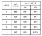
- FIG. 4 is an explanatory diagram showing an example of imaging conditions.
- FIG. 11 is an explanatory diagram showing an example of a necessary image required for generating a pseudo image.
- FIG. 11 is an explanatory diagram showing an example of how a pseudo image is generated.
- FIG. 2 is an explanatory diagram showing an example of a part P to be imaged;
- FIG. 4 is an explanatory diagram showing an example of the relationship between shutter speed and luminance value.
- FIG. 4 is an explanatory diagram showing an example of a shutter speed coefficient.
- FIG. 4 is an explanatory diagram showing an example of a confirmation screen 50.
- FIG. 4 is an explanatory diagram showing an example of
- FIG. 1 is a schematic diagram of a mounting device 10.
- FIG. 2 is a schematic diagram of a mark camera 20.
- FIG. 3 is a block diagram showing the electrical connection between the mounting device 10 and a management device 40. Note that in this embodiment, the left-right direction in FIG. 1 is the X-axis direction, the front-rear direction is the Y-axis direction, and the up-down direction is the Z-axis direction.
- the mounting device 10 picks up components and mounts them on the board S, and includes a base 11, a board transport device 12, a mounting head 14, a moving device 16, a feeder 18, a parts camera 19, a mark camera 20, and a control device 30 (see Figure 3).
- Multiple mounting devices 10 are arranged side by side in the board transport direction (X-axis direction) to form a mounting line.
- the mounting line including the mounting devices 10 is managed by a management device 40 (see Figure 3).
- the substrate transport device 12 is installed on the base 11 and has a pair of conveyor belts that are spaced apart from each other in the front-to-back direction (Y-axis direction) and span the left-to-right direction (X-axis direction).
- the substrate S is transported from left to right in FIG. 1 by driving the conveyor belts.
- the feeders 18 are attached to a feeder table installed on the base 11 so that they are aligned in the left-right direction (X-axis direction).
- the feeders 18 are equipped with a reel around which a tape that contains the components is wound.
- the tape has a number of cavities formed at equal intervals that contain the components. The components in the cavities are exposed when the film covering the surface of the tape is peeled off just before the component supply position, and are then picked up (adsorbed) by the mounting head 14.
- the mounting head 14 comprises a holder that holds the nozzle 15, and a lifting device that raises and lowers the holder.
- the nozzle 15 has a suction port at its tip, and adsorbs the component by negative pressure supplied to the suction port from a negative pressure source (not shown).
- the mounting head 14 may be a head with a single nozzle 15, or a rotary head with multiple nozzles 15 spaced equally around the circumference of a cylindrical head body. Also, instead of the nozzle 15, a mechanical chuck or an electromagnetic chuck may be used as a member for picking up the component.
- the moving device 16 moves the mounting head 14 back and forth and left and right (XY axis directions) along the XY plane (horizontal plane).
- the part camera 19 is installed on the base 11, images the components picked up by the nozzle 15 from below, and outputs the captured image to the control device 30.
- the mark camera 20 is installed below the mounting head 14, and moves back and forth and left and right (XY axis directions) together with the mounting head 14 by the moving device 16.
- the mark camera 20 images the object to be imaged from above, and outputs the captured image to the control device 30. Examples of objects to be imaged include marks affixed to the board S, components in cavities in the tape fed by the feeder 18, and components after being mounted on the board S.
- the mark camera 20 includes an illumination unit 21 and an imaging unit 25.
- the illumination unit 21 includes a side illumination unit 22 and an incident illumination unit (coaxial incident illumination unit) 23.
- the imaging unit 25 includes a lens 26, a shutter 27, and an image sensor 28.
- the side illumination unit 22 shines light diagonally onto the object.
- the side illumination unit 22 includes multiple light sources with different lighting colors, for example, a red LED 22r that emits R (red) light and a blue LED 22b that emits B (blue) light. When viewed from above, the LEDs 22r, 22b are arranged in a ring shape around the lens 26.
- the incident illumination unit 23 shines light onto the object from the same direction as the optical axis of the lens 26.
- the incident illumination unit 23 includes a half mirror 24 arranged at an angle of 45 degrees to the optical axis of the lens 26, and a light source that irradiates the half mirror 24 with light in a direction perpendicular to the optical axis of the lens 26 (horizontal direction).
- the light source of the incident illumination unit 23 includes a plurality of light sources with different lighting colors, for example, a red LED 23r that emits R (red) light and a blue LED 23b that emits B (blue) light.
- the side illumination unit 22 and the incident illumination unit 23 may each include a green LED that emits G (green) light.
- the lighting unit 21 has three lighting patterns: a side lighting pattern in which only the side lighting unit 22 is lit, an incident lighting pattern in which only the incident lighting unit 23 is lit, and a full lighting pattern in which both the side lighting unit 22 and the incident lighting unit 23 are lit. In each lighting pattern, the lighting unit 21 lights up either the R or B lighting color.
- the shutter 27 is disposed between the lens 26 and the image sensor 28, and adjusts the exposure time of the image sensor 28 when capturing an image by switching between passing and blocking the light that has passed through the lens 26. This exposure time can be adjusted by setting the shutter speed of the shutter 27.
- the image sensor 28 is configured as a monochrome image sensor (e.g., a monochrome CCD, etc.) that generates a monochromatic image based on the light it receives.
- the image sensor 28 receives light emitted from the side illumination unit 22 or the incident illumination unit 23 and reflected by the object via the half mirror 24 and the lens 26 to generate an image.
- the control device 30 includes a CPU 32, ROM 34, RAM 36, a storage unit 38 such as a hard disk or solid state drive, and input/output ports and communication ports (not shown).
- the control device 30 outputs various control signals to the board transport device 12, the mounting head 14, the moving device 16, the feeder 18, the parts camera 19, the mark camera 20, and the like.
- the control device 30 also inputs detection signals from various sensors including a position sensor that detects the position of the mounting head 14, and inputs images captured by the parts camera 19 and the mark camera 20.
- the control device 30 processes the images captured by the parts camera 19 and the mark camera 20 to perform various processes.
- the control device 30 is connected to the management device 40 via a communication network so as to be able to communicate in both directions, and exchanges data and control signals with each other.
- the management device 40 is a general-purpose computer and includes a management control unit 42 consisting of a CPU, ROM, RAM, etc., an input device 44 such as a keyboard or mouse that allows the worker to perform various input operations, a display 46 that displays various information, and a memory unit 48 such as a hard disk or solid state drive.
- the memory unit 48 stores a production schedule for the boards S.
- the production schedule determines which components are to be mounted on which boards S by the mounting device 10, and how many boards S with such components mounted are to be produced.
- the management device 40 instructs the control device 30 of the mounting device 10 to produce boards S with components mounted in accordance with the production schedule.
- the mounting device 10 configured in this manner performs a mounting process in which components are picked up and mounted on the board S as follows.
- the CPU 32 moves the mounting head 14 (nozzle 15) above the component supply position of the feeder 18, and lowers the nozzle 15 to pick up the component onto the nozzle 15.
- the CPU 32 moves the mounting head 14 above the board S via above the parts camera 19, and lowers the nozzle 15 to mount the component on the board S.
- the CPU 32 repeats this process for all components to be mounted.
- the CPU 32 processes the images captured by the parts camera 19 and the mark camera 20 to perform various recognition processes, and performs processing according to the recognition results.
- the CPU 32 causes the parts camera 19 to capture the component adsorbed to the nozzle 15, processes the captured image to recognize the adsorption deviation of the component relative to the nozzle 15 (image center), and corrects the target mounting position to eliminate the adsorption deviation.
- the CPU 32 also causes the mark camera 20 to capture the mark attached to the board S, processes the captured image to recognize the mark, and sets the mounting position coordinates of the component with the recognized position as the reference position.
- the CPU 32 also causes the mark camera 20 to capture the component in the cavity sent to the component supply position of the feeder 18, processes the captured image to recognize the positional deviation of the component relative to the cavity center, and corrects the adsorption position of the component to eliminate the positional deviation.
- the CPU 32 also processes the image captured by the mark camera 20 to recognize the component name, model, etc., and judges whether the component is correct or not.
- Predetermined imaging conditions are registered in the storage unit 38 so that each image is captured under optimal imaging conditions suited to the object being imaged. Below, an example of the process of registering imaging conditions for the mark camera 20 to image the part P as the object is described.
- FIG. 4 is a flow chart showing an example of an imaging condition registration process, which is executed by the management control unit 42 (CPU) of the management device 40.
- the management control unit 42 first sets one or more imaging conditions out of a plurality of imaging conditions that define a lighting color, a lighting pattern, and a shutter speed (SS) (S100).
- the mark camera 20 of this embodiment can set, for example, two lighting colors (R or B), three lighting patterns (side illumination pattern, incident illumination pattern, or full illumination pattern), and 20 shutter speeds in 5 ms increments between 5 ms and 100 ms, resulting in a total of 120 imaging conditions.
- the management control unit 42 sets ten imaging conditions, condition 1 to condition 10, for example, in S100.
- conditions 1 to 8 are eight conditions in total, including two lighting colors, R or B, two lighting patterns, side-illumination or incident-illumination, and two shutter speeds, SS1 or SS2 (>SS1).
- Conditions 9 and 10 are two conditions in total, including shutter speeds of SS1 or SS2 with all of the multiple lights turned off.
- Conditions 1 to 8 are also called imaging conditions for a first lighting pattern in which one of the multiple lights is turned on, and conditions 9 and 10 are also called imaging conditions for a second lighting pattern in which all of the multiple lights are turned off.
- Conditions 9 and 10 are not imaging conditions that are actually used, but are set for generating images of all lighting patterns.
- imaging conditions 1 to 10 are the minimum imaging conditions required to generate images of all imaging conditions other than the 10 imaging conditions, that is, the remaining 110 imaging conditions.
- the management control unit 42 causes the mark camera 20 to capture an image of the component P based on the imaging conditions set in S100 (S110).
- the management control unit 42 transmits an instruction to capture an image based on the imaging conditions determined in S100 to the control device 30 of the mounting device 10.
- the control device 30 controls the mark camera 20 to capture an image, and transmits the captured image to the management control unit 42.
- a total of 10 images of the component P are captured based on the 10 imaging conditions that have been set. Therefore, the number of images captured can be significantly reduced, and the imaging time in S110 can be significantly shortened, compared to the case where all 120 images are captured based on the 120 imaging conditions.
- FIG. 6 is an explanatory diagram showing an example of a necessary image required for generating a pseudo image.
- FIG. 7 is an explanatory diagram showing an example of a manner in which a pseudo image is generated. As shown in FIG. 6, a pseudo image is generated by selecting two images (image 1 and image 2) captured under any of conditions 1 to 8, adding the luminance values of each pixel of the selected images, and subtracting the luminance value of each pixel of image 3 captured under any of conditions 9 and 10 by one image.
- the luminance value of each pixel of image 1 captured under condition 1 is added to the luminance value of each pixel of image 2 captured under condition 3, and the luminance value of each pixel of image 3 captured under condition 9 is subtracted to generate a pseudo image No. 1 with a lighting color of R, a lighting pattern of all lighting patterns, and a shutter speed of SS1 (see FIG. 7).
- an image of a full lighting pattern of any lighting color is generated in a pseudo manner by adding the luminance value of an image of a side-illumination pattern of the same lighting color and the luminance value of an image of an incident light pattern of the same lighting color, and subtracting the luminance value of an image of an off-pattern.
- the luminance values of two images are added together, and the luminance value of an image of an off-pattern that is one value less than value 2 is subtracted.
- the shutter speed of the image whose luminance values are added and the image whose luminance value is subtracted are both the same.
- the images of the off-pattern conditions 9 and 10 can be used for both R and B lighting colors, the number of images that need to be captured can be reduced. In other words, the number of images that need to be captured can be reduced, and the capture time of S110 can be shortened, compared to the case where each image of the side-illumination pattern, incident light pattern, and full lighting pattern of the lighting color R is captured, and each image of the side-illumination pattern, incident light pattern, and full lighting pattern of the lighting color B is captured.
- FIG. 8 is an explanatory diagram showing an example of a part P to be imaged.
- the part P has a resin body B that is rectangular in top view, and a plurality of metal leads L that protrude outward from the body B.
- FIG. 9 is an explanatory diagram showing an example of the relationship between shutter speed and luminance value.
- the horizontal axis represents shutter speed
- the vertical axis represents luminance value
- the actual luminance change is shown by a solid line.
- the lead L tends to have a higher luminance value than the body B, but each luminance value has a linear relationship with the shutter speed.
- the management control unit 42 obtains an approximate linear relationship between the luminance value and the shutter speed (see the dotted line in FIG. 9) for each pixel.
- FIG. 10 is an explanatory diagram showing an example of a shutter speed coefficient.
- the management control unit 42 obtains the slope a and intercept b of the linear relational expression as the shutter speed coefficient for each pixel in the image, in association with the lighting color (R, B) and the lighting pattern (side illumination, incident illumination, full illumination).
- the management control unit 42 obtains the correspondence between the brightness value and the shutter speed for each pixel from two images captured under conditions 1 and 2, which have the same lighting color and lighting pattern but different shutter speeds, and calculates and obtains the slope a and intercept b of each pixel when the lighting color is R and the lighting pattern is a side illumination pattern based on the correspondence between the two points.
- the management control unit 42 also obtains the shutter speed coefficient from the pseudo image generated in the pseudo image generation process. For example, the management control unit 42 obtains two correspondences between the brightness value and the shutter speed for each pixel from two pseudo images No. 1 and No. 2 that have the same lighting color and lighting pattern but different shutter speeds, and obtains the slope a and intercept b of each pixel when the lighting color is R and the lighting pattern is the full lighting pattern based on the correspondences between the two points.
- the management control unit 42 displays a confirmation screen for allowing the user (operator) to confirm the image and imaging conditions (S140).
- the management control unit 42 displays a confirmation screen 50 as shown in Figs. 11 and 12 on the display 46.
- the confirmation screen 50 is provided with an image display field 51, a lighting color designation field 52, a lighting pattern designation field 53, a slider 54, a shutter speed display field 55, a back button 56, and a decision button 57.
- an instruction pointer (mouse pointer) 50a that is operated by an input device 44 such as a mouse is displayed on the confirmation screen 50.
- the image display field 51 an image based on the imaging conditions specified by the user is displayed.
- the lighting color can be specified by clicking the instruction pointer 50a, and each time the instruction pointer 50a is clicked, the color switches between R and B.
- the lighting pattern specification field 53 the lighting pattern can be specified by clicking the instruction pointer 50a, and each time the instruction pointer 50a is clicked, the color switches between a side illumination pattern, a vertical illumination pattern, and a full illumination pattern.
- the slider 54 can be slid left and right by dragging the instruction pointer 50a to specify the shutter speed in 5 ms increments, and the shutter speed is changed to a larger value as the slider is slid from left to right.
- the shutter speed display field 55 displays the shutter speed changed by the slider 54.
- the back button 56 is a button for returning to the imaging conditions and image before the specification was accepted.
- the decision button 57 is a button for deciding on the imaging conditions of the currently displayed image. The back button 56 and the decision button 57 are clicked with the instruction pointer 50a.
- the management control unit 42 determines whether or not a designation operation (change operation) of the image capture conditions has been performed based on the user's operation on the confirmation screen 50 (S150), and if it determines that a designation operation has not been performed, it proceeds to S200.
- the designation operation of the image capture conditions corresponds to the designation of the illumination color in the illumination color designation field 52, the designation of the illumination pattern in the illumination pattern designation field 53, and the designation of the shutter speed with the slider 54.
- the management control unit 42 determines that a designation operation has been performed, it determines whether or not the designated image capture conditions (also called the designated conditions) are different from the image capture conditions set in S100, i.e., the image capture conditions captured by the mark camera 20 (S160).
- the management control unit 42 determines in S160 that they are not different image capture conditions, reads out the image captured under the designated conditions (S170), displays it in the image display field 51 (S180), and proceeds to S200.
- the management control unit 42 determines in S160 that the specified condition is a different imaging condition, generates an image based on the specified condition (S190), displays it in the image display field 51 (S180), and proceeds to S200.
- the management control unit 42 generates an image based on the specified lighting color, lighting pattern, and shutter speed, and displays it in the image display field 51. That is, the management control unit 42 reads out the shutter speed coefficient (slope a, intercept b) corresponding to the specified lighting color and lighting pattern (see FIG. 10), calculates the luminance value of each pixel based on the shutter speed coefficient and the specified shutter speed, and displays the generated image. For example, in FIG.
- the slider 54 is slid to the right more than in FIG. 11, and a larger shutter speed is specified, so that a brighter image with a larger luminance value than in FIG. 11 is generated and displayed in the image display field 51.
- the management control unit 42 calculates the brightness value of each pixel in the image of the full lighting pattern generated in the pseudo image generation process based on the shutter speed coefficient and the specified shutter speed to generate an image, and displays the generated image in the image display area 51.
- the user can also confirm the images displayed in the image display field 51, select an image that is considered to be easy to recognize the component P in image processing, i.e., suitable for image processing, and determine the imaging conditions by operating the decision button 57 (decision operation).
- the management control unit 42 determines whether or not the decision operation for the imaging conditions has been performed (S200), and returns to S150 if it determines that the decision operation has not been performed. Note that a description of the case where the back button 56 is operated will be omitted.
- the management control unit 42 determines that the decision operation has been performed, it registers the imaging conditions of the displayed image in association with the component P (S210), and ends the imaging condition registration process.
- the imaging conditions are transmitted from the management device 40 to the control device 30 of the mounting device 10 and registered in the storage unit 38. Thereafter, when the control device 30 images the component P, it controls the mark camera 20 based on the imaging conditions to capture the image.
- the management control unit 42 that executes S100 and S110 of the imaging condition registration process of this embodiment corresponds to the imaging control unit of this disclosure
- the management control unit 42 that executes S120, S130, and S190 of the same process corresponds to the image generation unit
- the management control unit 42 that executes S140, S170, and S180 of the same process corresponds to the display control unit
- the management control unit 42 that executes S200 and S210 of the same process corresponds to the determination unit.
- an example of the image display method of the present disclosure is also clarified by explaining the operation of the management device 40.
- 10 imaging conditions out of multiple (e.g. 120) imaging conditions are set, and an image based on the set imaging conditions is captured by the mark camera 20 (imaging device).
- an image based on imaging conditions other than the set ones is generated using an image captured by the mark camera 20, and the image captured or generated by the mark camera 20 and the imaging conditions of the image are displayed on the display 46 (display device) so that the user can check them.
- This makes it possible to display an image and its imaging conditions without capturing all images based on multiple imaging conditions. Therefore, it is possible to appropriately check the image and its imaging conditions while reducing the time required to acquire the image.
- the minimum imaging conditions necessary to generate all images based on imaging conditions other than the set ones are set as the 10 imaging conditions. Therefore, the number of images captured by the mark camera 20 is minimized, and the time required to acquire images can be reliably reduced.
- the imaging conditions for the mark camera 20 to capture an image of the target object are determined based on the user's confirmation operation (confirmation result) for the image displayed on the confirmation screen 50 of the display 46. By reducing the time required to capture an image, the imaging conditions can also be determined quickly.
- imaging conditions imaging conditions for a first lighting pattern in which one of the multiple lights is turned on are set for each lighting color (R, B) and each lighting (side illumination, incident illumination), and imaging conditions for a second lighting pattern in which all of the multiple lights are turned off are set. Then, two images required to generate an image of all lighting patterns in which all lights are turned on are selected from the images captured with the first lighting pattern, and the luminance values of each pixel are added together, and the luminance value of each pixel of the image captured with the second lighting pattern is subtracted by one image, thereby generating an image of all lighting patterns. Therefore, even if images of all lighting patterns that can be set by the multiple lights provided for each of the multiple lighting colors are not captured, images can be appropriately generated and displayed according to the lighting color and whether each light is turned on or off.
- R, B lighting color
- side illumination, incident illumination side illumination, incident illumination
- a relational equation (shutter speed coefficient) between shutter speed and luminance value is set for each pixel based on the luminance value of each pixel in images captured under imaging conditions with two different shutter speeds (SS1, SS2). Then, the luminance value of each pixel corresponding to the specified shutter speed is calculated based on the relational equation, and an image corresponding to the shutter speed is generated and displayed. Therefore, it is possible to appropriately generate and display an image corresponding to any shutter speed, without having to capture images at all shutter speeds.
- images are captured at two different shutter speeds (SS1, SS2), but this is not limited to the above.
- images may be captured under two or more imaging conditions with different shutter speeds so that the relationship between the shutter speed and the brightness value can be set for each pixel.
- imaging conditions for the first lighting pattern and two imaging conditions for the second lighting pattern are set as the ten imaging conditions, and images of all lighting patterns are generated using images of the first lighting pattern and images of the second lighting pattern, but this is not limited to this.
- one or more imaging conditions set among the multiple imaging conditions may be imaging conditions necessary to generate an image under imaging conditions other than those set, i.e., imaging conditions that were not captured by the mark camera 20.
- items such as lighting color, whether or not lighting is on, and shutter speed are examples of imaging conditions, and it is not necessary that any of these items can be set, or items other than these may be set.
- the shutter speed is SS2
- two images with conditions 2 and 6 are selected as the image of the first lighting pattern, the luminance values are added together, and an image with condition 10 is selected as the image of the second lighting pattern, and the luminance value is subtracted by one image.
- Images of incident light patterns can also be generated in a similar manner.
- an image of condition 1 in which the lighting color is R and the side-illumination pattern, an image of condition 3 in which the lighting color is R and the incident-illumination pattern, an image of condition 5 in which the lighting color is B and the side-illumination pattern, and an image of condition 7 in which the lighting color is B and the incident-illumination pattern are selected as the image of the first lighting pattern.
- the luminance values of each pixel of the selected four images are added together, and the luminance value of each pixel of the image of condition 9 as the image of the second lighting pattern is subtracted by three images (multiplied by three), thereby generating an image of all lighting patterns with a shutter speed of SS1 and a lighting color of P. If the shutter speed is SS2, the four images of condition 2, condition 4, condition 6, and condition 8 are selected as the image of the first lighting pattern, and the luminance values are added together, and the image of condition 10 is selected as the image of the second lighting pattern, and the luminance value is subtracted by three images.
- the necessary images are selected from the images captured with the first lighting pattern, the luminance values of each pixel of the selected n images are added together, and the luminance value of each pixel of the image captured with the second lighting pattern is subtracted by a value (n-1) to calculate the luminance value of each pixel and generate an image.
- ten imaging conditions are set as the minimum necessary imaging conditions, but this is not limiting and a number of imaging conditions exceeding the minimum necessary may be set. For example, fifteen imaging conditions may be set so that there are three shutter speeds instead of two. In this way, the accuracy of setting the shutter speed coefficient can be improved, and pseudo images can be generated with greater accuracy.
- the imaging conditions of the mark camera 20 are determined as an example, but the present invention is not limited to this and imaging conditions of the parts camera 19 may be determined. Furthermore, the present invention is not limited to determining imaging conditions, but may simply display an image and its imaging conditions on the display 46 so that the user can check them. Furthermore, the management device 40 (management control unit 42) has the functions of an imaging control unit, an image generation unit, and a display control unit, but the control device 30 or another device may have some of these functions. Note that the imaging device is not limited to the one used in the mounting device 10, and the display device is not limited to the display 46 of the management device 40. Furthermore, the present invention is not limited to the technical field of component mounting processing, and may be applied to image display in other technical fields.
- This disclosure can be used in technical fields such as image processing and component mounting processing.
Landscapes
- Engineering & Computer Science (AREA)
- Multimedia (AREA)
- Signal Processing (AREA)
- Human Computer Interaction (AREA)
- Studio Devices (AREA)
- Image Input (AREA)
Priority Applications (4)
| Application Number | Priority Date | Filing Date | Title |
|---|---|---|---|
| PCT/JP2023/018992 WO2024241439A1 (ja) | 2023-05-22 | 2023-05-22 | 画像表示システムおよび画像表示方法 |
| DE112023006387.7T DE112023006387T5 (de) | 2023-05-22 | 2023-05-22 | Bildanzeigesystem und Bildanzeigeverfahren |
| JP2025521649A JPWO2024241439A1 (https=) | 2023-05-22 | 2023-05-22 | |
| CN202380098277.XA CN121128160A (zh) | 2023-05-22 | 2023-05-22 | 图像显示系统及图像显示方法 |
Applications Claiming Priority (1)
| Application Number | Priority Date | Filing Date | Title |
|---|---|---|---|
| PCT/JP2023/018992 WO2024241439A1 (ja) | 2023-05-22 | 2023-05-22 | 画像表示システムおよび画像表示方法 |
Publications (1)
| Publication Number | Publication Date |
|---|---|
| WO2024241439A1 true WO2024241439A1 (ja) | 2024-11-28 |
Family
ID=93589633
Family Applications (1)
| Application Number | Title | Priority Date | Filing Date |
|---|---|---|---|
| PCT/JP2023/018992 Ceased WO2024241439A1 (ja) | 2023-05-22 | 2023-05-22 | 画像表示システムおよび画像表示方法 |
Country Status (4)
| Country | Link |
|---|---|
| JP (1) | JPWO2024241439A1 (https=) |
| CN (1) | CN121128160A (https=) |
| DE (1) | DE112023006387T5 (https=) |
| WO (1) | WO2024241439A1 (https=) |
Citations (4)
| Publication number | Priority date | Publication date | Assignee | Title |
|---|---|---|---|---|
| JP2006261912A (ja) * | 2005-03-16 | 2006-09-28 | Casio Comput Co Ltd | 撮影装置 |
| JP2010171777A (ja) * | 2009-01-23 | 2010-08-05 | Toyota Motor Corp | 撮像装置 |
| JP2017208641A (ja) * | 2016-05-17 | 2017-11-24 | キヤノン株式会社 | 圧縮センシングを用いた撮像装置、撮像方法および撮像プログラム |
| WO2020255365A1 (ja) * | 2019-06-21 | 2020-12-24 | 株式会社Fuji | 画像合成装置、画像取得装置、画像処理システム、画像処理方法 |
-
2023
- 2023-05-22 WO PCT/JP2023/018992 patent/WO2024241439A1/ja not_active Ceased
- 2023-05-22 JP JP2025521649A patent/JPWO2024241439A1/ja active Pending
- 2023-05-22 DE DE112023006387.7T patent/DE112023006387T5/de active Pending
- 2023-05-22 CN CN202380098277.XA patent/CN121128160A/zh active Pending
Patent Citations (4)
| Publication number | Priority date | Publication date | Assignee | Title |
|---|---|---|---|---|
| JP2006261912A (ja) * | 2005-03-16 | 2006-09-28 | Casio Comput Co Ltd | 撮影装置 |
| JP2010171777A (ja) * | 2009-01-23 | 2010-08-05 | Toyota Motor Corp | 撮像装置 |
| JP2017208641A (ja) * | 2016-05-17 | 2017-11-24 | キヤノン株式会社 | 圧縮センシングを用いた撮像装置、撮像方法および撮像プログラム |
| WO2020255365A1 (ja) * | 2019-06-21 | 2020-12-24 | 株式会社Fuji | 画像合成装置、画像取得装置、画像処理システム、画像処理方法 |
Also Published As
| Publication number | Publication date |
|---|---|
| CN121128160A (zh) | 2025-12-12 |
| DE112023006387T5 (de) | 2026-03-12 |
| JPWO2024241439A1 (https=) | 2024-11-28 |
Similar Documents
| Publication | Publication Date | Title |
|---|---|---|
| US9474195B2 (en) | Image generating apparatus and image generating method | |
| JP2001520392A (ja) | 構成要素および/または基板の位置識別および/または品質検査のための装置における照明設定方法 | |
| JP7594632B2 (ja) | 対基板作業システム | |
| JP6714393B2 (ja) | 計測装置、システム、計測方法、および物品の製造方法 | |
| JP7301973B2 (ja) | 検査装置 | |
| US11971367B2 (en) | Inspection device and inspection method | |
| WO2019111331A1 (ja) | 撮像ユニット及び部品実装機 | |
| WO2024241439A1 (ja) | 画像表示システムおよび画像表示方法 | |
| US11997375B2 (en) | Image correction method, imaging device, and inspection device | |
| JP7271738B2 (ja) | 撮像ユニット | |
| JP7562860B2 (ja) | 部品実装機 | |
| WO2018055757A1 (ja) | 照明条件特定装置及び照明条件特定方法 | |
| WO2024009410A1 (ja) | 部品有無判定方法および画像処理システム | |
| JPH07151523A (ja) | 電子部品検査装置 | |
| EP3767938B1 (en) | Image-capturing unit and component-mounting device | |
| WO2024189728A1 (ja) | 検査装置および検査システム | |
| WO2020065698A1 (ja) | 部品データ、部品データ作成システム、部品実装機及び部品実装ラインの生産最適化システム | |
| WO2018055663A1 (ja) | 撮像装置及び実装装置 | |
| CN116364592A (zh) | 半导体制造设施及半导体制造设施的教导方法 | |
| CN113228847A (zh) | 元件安装机 | |
| JPH0448800A (ja) | 基板認識装置 |
Legal Events
| Date | Code | Title | Description |
|---|---|---|---|
| 121 | Ep: the epo has been informed by wipo that ep was designated in this application |
Ref document number: 23938411 Country of ref document: EP Kind code of ref document: A1 |
|
| ENP | Entry into the national phase |
Ref document number: 2025521649 Country of ref document: JP Kind code of ref document: A |
|
| WWE | Wipo information: entry into national phase |
Ref document number: 112023006387 Country of ref document: DE |
|
| WWP | Wipo information: published in national office |
Ref document number: 112023006387 Country of ref document: DE |