WO2024237336A1 - ロータリ圧縮機 - Google Patents
ロータリ圧縮機 Download PDFInfo
- Publication number
- WO2024237336A1 WO2024237336A1 PCT/JP2024/018351 JP2024018351W WO2024237336A1 WO 2024237336 A1 WO2024237336 A1 WO 2024237336A1 JP 2024018351 W JP2024018351 W JP 2024018351W WO 2024237336 A1 WO2024237336 A1 WO 2024237336A1
- Authority
- WO
- WIPO (PCT)
- Prior art keywords
- injection
- rotary compressor
- tube
- hole
- diameter portion
- Prior art date
- Legal status (The legal status is an assumption and is not a legal conclusion. Google has not performed a legal analysis and makes no representation as to the accuracy of the status listed.)
- Ceased
Links
Images








Classifications
-
- F—MECHANICAL ENGINEERING; LIGHTING; HEATING; WEAPONS; BLASTING
- F04—POSITIVE - DISPLACEMENT MACHINES FOR LIQUIDS; PUMPS FOR LIQUIDS OR ELASTIC FLUIDS
- F04C—ROTARY-PISTON, OR OSCILLATING-PISTON, POSITIVE-DISPLACEMENT MACHINES FOR LIQUIDS; ROTARY-PISTON, OR OSCILLATING-PISTON, POSITIVE-DISPLACEMENT PUMPS
- F04C29/00—Component parts, details or accessories of pumps or pumping installations, not provided for in groups F04C18/00 - F04C28/00
- F04C29/04—Heating; Cooling; Heat insulation
-
- F—MECHANICAL ENGINEERING; LIGHTING; HEATING; WEAPONS; BLASTING
- F04—POSITIVE - DISPLACEMENT MACHINES FOR LIQUIDS; PUMPS FOR LIQUIDS OR ELASTIC FLUIDS
- F04C—ROTARY-PISTON, OR OSCILLATING-PISTON, POSITIVE-DISPLACEMENT MACHINES FOR LIQUIDS; ROTARY-PISTON, OR OSCILLATING-PISTON, POSITIVE-DISPLACEMENT PUMPS
- F04C29/00—Component parts, details or accessories of pumps or pumping installations, not provided for in groups F04C18/00 - F04C28/00
- F04C29/12—Arrangements for admission or discharge of the working fluid, e.g. constructional features of the inlet or outlet
Definitions
- An embodiment of the present invention relates to a rotary compressor.
- a known type of rotary compressor has a compressor unit that compresses the refrigerant and a motor that drives the compressor unit, both of which are arranged inside the compressor body container.
- This type of rotary compressor is installed in, for example, a refrigeration cycle device.
- an on-off valve is provided in the injection passage branched off from the condenser outlet, making it possible to switch whether or not injection (injection operation) is performed.
- injection operation when injection operation is not performed, the space from the on-off valve provided in the injection passage to the cylinder chamber becomes a dead volume. This causes the compressed refrigerant to expand again, reducing compression efficiency.
- a slide valve is provided in an injection passage extending radially of a partition plate, and when an injection port communicating with a cylinder chamber is opened, the slide valve is not positioned within the injection passage.
- the slide valve is positioned at the injection port position to prevent refrigerant from flowing back into the injection passage, thereby reducing the dead volume when injection operation is not performed.
- This type of slide structure has the problem that the spring and slide valve structures are complex and difficult to manufacture. In addition, there is a risk that the reliability of the compressor will decrease if injection is not performed normally due to a malfunction of the slide structure, etc.
- the disclosed technology has been developed in consideration of the above, and aims to provide a rotary compressor equipped with an injection mechanism that can reduce dead volume while facilitating manufacturing.
- the rotary compressor includes a compression section that compresses a refrigerant, a motor that drives the compression section, and a compressor main body container that houses the compression section and the motor.
- the compression section has a cylinder that forms a cylinder chamber therein, a piston that revolves around the inner circumference of the cylinder, and an end plate that closes the end of the cylinder.
- the end plate has an injection hole that communicates with the cylinder chamber and through which an injection tube that conducts the refrigerant can be inserted.
- the injection tube is fixed in the injection hole via a holding tube that holds the outer circumference of the injection tube.
- the disclosed technology makes it possible to reduce dead volume while facilitating manufacturing.
- FIG. 1 is a vertical cross-sectional view illustrating an example of a rotary compressor according to an embodiment.
- FIG. 2 is a top cross-sectional view of the first compression section and the second compression section.
- FIG. 3 is a partial vertical cross-sectional view showing a compression unit of the rotary compressor according to the embodiment.
- FIG. 4 is a partial vertical cross-sectional view showing an injection hole of the intermediate partition plate.
- FIG. 5 is a partial vertical cross-sectional view showing an injection hole in the intermediate partition plate.
- FIG. 6 is a partial vertical cross-sectional view showing an injection hole in the intermediate partition plate.
- FIG. 7 is a partial vertical cross-sectional view showing an injection hole in the intermediate partition plate.
- FIG. 8 is an explanatory diagram for explaining a comparison of the dead volume in the injection mechanism of a rotary compressor with a conventional example.
- FIG. 9 is a radial cross-sectional view and a cross-sectional view in a direction perpendicular to the axis of rotation, showing the rotation cycle of an annular piston in a conventional rotary compressor.
- FIG. 10 is a graph showing pressure changes in the cylinder of a conventional rotary compressor when the injection operation is not performed.
- FIG. 11 is a radial cross-sectional view showing a rotation cycle of an annular piston in the rotary compressor according to the embodiment, and a cross-sectional view in a direction perpendicular to the rotation axis.
- FIG. 12 is a graph showing a pressure change in the cylinder when the injection operation is not performed in the rotary compressor according to the embodiment.
- FIG. 13 is a partial vertical sectional view showing a compression portion of a rotary compressor according to the first modification.
- FIG. 14 is a partial vertical sectional view showing a compression portion of a rotary compressor according to the second modification.
- FIG. 15 is an exploded perspective view of the intermediate partition plate.
- FIG. 16 is an explanatory diagram for explaining the dead volume from the connecting valve.
- FIG. 17 is an enlarged view of the dotted line portion of FIG.
- FIG. 1 is a vertical cross-sectional view showing an example of a rotary compressor according to an embodiment.
- FIG. 2 is a horizontal cross-sectional view seen from above of the first compression section and the second compression section.
- the rotary compressor 1 includes a compression section 12 arranged at the bottom of a sealed, vertically-mounted cylindrical compressor housing 10, and a motor 11 arranged at the top of the compressor housing 10, which drives the compression section 12 via a rotating shaft 15.
- the stator 111 of the motor 11 is formed in a cylindrical shape and is fixed by shrink fitting to the inner peripheral surface of the compressor housing 10.
- the rotor 112 of the motor 11 is disposed inside the cylindrical stator 111 and is fixed by shrink fitting to the rotating shaft 15 that mechanically connects the motor 11 and the compression section 12.
- the compression section 12 includes a first compression section 12S and a second compression section 12T arranged in parallel with the first compression section 12S and stacked on the upper side of the first compression section 12S.
- the first compression section 12S includes an annular first cylinder 121S having a first suction hole 135S and a first vane groove 128S arranged radially in a first lateral projection 122S.
- the second compression section 12T includes an annular second cylinder 121T having a second suction hole 135T and a second vane groove 128T arranged radially in a second lateral projection 122T.
- the first cylinder 121S is formed with a first vane groove 128S extending radially from the first cylinder inner wall 123S across the entire cylinder height.
- the second cylinder 121T is formed with a second vane groove 128T extending radially from the second cylinder inner wall 123T across the entire cylinder height.
- a flat first vane 127S and a flat second vane 127T are slidably fitted into the first vane groove 128S and the second vane groove 128T, respectively.
- a first spring hole 124S is formed at the back of the first vane groove 128S so as to connect from the outer periphery of the first cylinder 121S to the first vane groove 128S.
- a second spring hole 124T is formed at the back of the second vane groove 128T so as to connect from the outer periphery of the second cylinder 121T to the second vane groove 128T.
- a first vane spring 260S (see FIG. 3) that presses against the back surface of the first vane 127S is inserted into the first spring hole 124S.
- a second vane spring 260T (see FIG. 3) that presses against the back surface of the second vane 127T is inserted into the second spring hole 124T.
- the first vane 127S protrudes from the first vane groove 128S into the first cylinder chamber 130S due to the repulsive force of the first vane spring 260S.
- the second vane 127T protrudes from the second vane groove 128T into the second cylinder chamber 130T due to the repulsive force of the second vane spring 260T.
- the tip of the first vane 127S abuts against the outer peripheral surface of the first annular piston 125S.
- the tip of the second vane 127T abuts against the outer peripheral surface of the second annular piston 125T.
- the first vane 127S By the first vane 127S abutting in this manner, the first cylinder chamber 130S is divided into a first suction chamber 131S and a first compression chamber 133S. Additionally, the second vane 127T divides the second cylinder chamber 130T into a second suction chamber 131T and a second compression chamber 133T.
- the first and second cylinders 121S, 121T also have an opening R, shown in FIG. 1, that connects the innermost parts of the first and second vane grooves 128S, 128T to the inside of the compressor housing 10.
- Compressed refrigerant gas is introduced into the compressor housing 10 from this opening R, and first and second pressure introduction passages 129S, 129T are formed that apply back pressure to the first and second vanes 127S, 127T by the pressure of the refrigerant gas.
- the first and second cylinders 121S, 121T are provided with first and second suction holes 135S, 135T that connect the first and second suction chambers 131S, 131T to the outside in order to draw refrigerant from the outside into the first and second suction chambers 131S, 131T.
- an intermediate partition plate 140 is disposed between the first cylinder 121S and the second cylinder 121T, partitioning and closing the first cylinder chamber 130S (see FIG. 2) of the first cylinder 121S and the second cylinder chamber 130T (see FIG. 2) of the second cylinder 121T.
- the intermediate partition plate 140 closes the upper end of the first cylinder 121S and the lower end of the second cylinder 121T.
- the intermediate partition plate 140 is an example of an end plate that closes the ends of a cylinder.
- a lower end plate 160S is disposed at the lower end of the first cylinder 121S, closing off the first cylinder chamber 130S of the first cylinder 121S. Additionally, an upper end plate 160T is disposed at the upper end of the second cylinder 121T, closing off the second cylinder chamber 130T of the second cylinder 121T. The lower end plate 160S closes off the lower end of the first cylinder 121S, and the upper end plate 160T closes off the upper end of the second cylinder 121T.
- the lower end plate 160S is formed with a secondary bearing portion 161S, and the secondary shaft portion 151 of the rotating shaft 15 is rotatably supported by the secondary bearing portion 161S.
- the upper end plate 160T is formed with a main bearing portion 161T, and the main shaft portion 153 of the rotating shaft 15 is rotatably supported by the main bearing portion 161T.
- the rotating shaft 15 has a first eccentric portion 152S and a second eccentric portion 152T that are eccentrically shifted from each other by 180°.
- the first eccentric portion 152S is rotatably fitted to the first annular piston 125S of the first compression section 12S.
- the second eccentric portion 152T is rotatably fitted to the second annular piston 125T of the second compression section 12T.
- the first and second annular pistons 125S, 125T revolve clockwise in FIG. 2 within the first and second cylinders 121S, 121T along the first and second cylinder inner walls 123S, 123T. Following this revolution, the first and second vanes 127S, 127T reciprocate. Due to the movement of the first and second annular pistons 125S, 125T and the first and second vanes 127S, 127T, the volumes of the first and second suction chambers 131S, 131T and the first and second compression chambers 133S, 133T change continuously. In addition, the compression section 12 continuously draws in, compresses, and discharges refrigerant gas.
- a lower muffler cover 170S is disposed below the lower end plate 160S, forming a lower muffler chamber 180S between the lower end plate 160S and the lower muffler cover 170S.
- the first compression section 12S opens into the lower muffler chamber 180S. That is, a first discharge hole 190S (see FIG. 2) that connects the first compression chamber 133S of the first cylinder 121S to the lower muffler chamber 180S is provided near the first vane 127S of the lower end plate 160S.
- a reed-type first discharge valve 200S that prevents backflow of compressed refrigerant gas is disposed in the first discharge hole 190S.
- the lower muffler chamber 180S is a single chamber formed in an annular shape, and is part of a communication passage that connects the discharge side of the first compression section 12S to the upper muffler chamber 180T through the refrigerant passage 136 (see FIG. 2) that penetrates the lower end plate 160S, the first cylinder 121S, the intermediate partition plate 140, the second cylinder 121T, and the upper end plate 160T.
- the lower muffler chamber 180S reduces pressure pulsation of the discharged refrigerant gas.
- a first discharge valve stopper 201S for limiting the amount of deflection of the first discharge valve 200S is fixed together with the first discharge valve 200S by rivets, overlapping the first discharge valve 200S.
- the first discharge hole 190S, the first discharge valve 200S, and the first discharge valve stopper 201S constitute the first discharge valve section of the lower end plate 160S.
- an upper muffler cover 170T is disposed above the upper end plate 160T, forming an upper muffler chamber 180T between the upper end plate 160T and the upper muffler cover 170T.
- a second discharge hole 190T (see FIG. 2) that connects the second compression chamber 133T of the second cylinder 121T to the upper muffler chamber 180T is provided near the second vane 127T of the upper end plate 160T.
- a reed valve type second discharge valve 200T that prevents backflow of compressed refrigerant gas is disposed in the second discharge hole 190T.
- a second discharge valve holder 201T that limits the amount of deflection of the second discharge valve 200T is fixed by rivets together with the second discharge valve 200T, overlapping the second discharge valve 200T.
- the upper muffler chamber 180T reduces pressure pulsation of the discharged refrigerant.
- the second discharge hole 190T, the second discharge valve 200T, and the second discharge valve retainer 201T constitute the second discharge valve portion of the upper end plate 160T.
- the first cylinder 121S, the lower end plate 160S, the lower muffler cover 170S, the second cylinder 121T, the upper end plate 160T, the upper muffler cover 170T, and the intermediate partition plate 140 are fastened together by a plurality of through bolts 175, etc.
- the outer periphery of the upper end plate 160T is fixed to the compressor housing 10 by spot welding, fixing the compression section 12 to the compressor housing 10.
- the outer peripheral wall of the cylindrical compressor housing 10 is provided with a first through hole 101 and a second through hole 102 spaced apart in the axial direction from the bottom to allow the first suction pipe 104 and the second suction pipe 105 to pass through.
- an accumulator 25 consisting of an independent cylindrical sealed container is held by an accumulator holder 252 and an accumulator band 253.
- a system connection pipe 255 that connects to the evaporator of the refrigerant circuit is connected to the center of the top of the accumulator 25.
- a first low-pressure connection pipe 31S and a second low-pressure connection pipe 31T are fixed to a bottom through hole 257 provided at the bottom of the accumulator 25.
- One end of the first low-pressure connection pipe 31S extends to the upper interior of the accumulator 25, and the other end of the first low-pressure connection pipe 31S is connected to the other end of the first suction pipe 104.
- the first low-pressure communication pipe 31S which guides the low-pressure refrigerant of the refrigerant circuit to the first compression section 12S via the accumulator 25, is connected to the first suction hole 135S (see FIG. 2) of the first cylinder 121S via the first suction pipe 104 as a suction section.
- the second low-pressure communication pipe 31T which guides the low-pressure refrigerant of the refrigerant circuit to the second compression section 12T via the accumulator 25, is connected to the second suction hole 135T (see FIG. 2) of the second cylinder 121T via the second suction pipe 105 as a suction section.
- the first suction hole 135S and the second suction hole 135T are connected in parallel to the evaporator of the refrigerant circuit.
- a discharge pipe 107 is connected to the top of the compressor housing 10 as a discharge part that connects to the refrigerant circuit and discharges high-pressure refrigerant gas to the condenser side of the refrigerant circuit. That is, the first discharge hole 190S and the second discharge hole 190T are connected to the condenser of the refrigerant circuit.
- Lubricating oil is sealed inside the compressor housing 10 up to about the height of the second cylinder 121T.
- the lubricating oil is sucked up from an oil supply pipe 16 attached to the lower end of the rotating shaft 15 by pump vanes (not shown) inserted into the lower part of the rotating shaft 15, and circulates through the compression section 12.
- the lubricating oil lubricates the sliding parts and seals the minute gaps in the compression section 12.
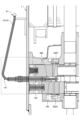
- Figure 3 is a partial vertical cross-sectional view showing the compression section 12 of the rotary compressor 1 according to the embodiment.
- the intermediate partition plate 140 is formed with an injection hole 300 that communicates with the first cylinder chamber 130S via a communication hole 302S and with the second cylinder chamber 130T via a communication hole 302T, and through which an injection tube 141 for supplying refrigerant can be inserted.
- the injection tube 141 is fixed to this injection hole 300 via a holding tube 142 that holds the outer periphery of the injection tube 141.
- Refrigeration cycle devices using heat pumps have recently become popular in cold regions with low outdoor temperatures.
- an evaporator is used in an environment with a low outdoor temperature, the density of the refrigerant drawn into the compression section 12 decreases, making it difficult to obtain sufficient heating capacity.
- a portion of the liquid refrigerant at the outlet side of the condenser or after passing through the pressure reducing means is branched, and the branched liquid refrigerant is injected into the first cylinder chamber 130S and the second cylinder chamber 130T of the compression section 12 via the injection pipe 141, i.e., liquid injection (or gas injection in which gaseous refrigerant is injected) is performed.
- the compressor By performing this liquid injection, the amount of refrigerant circulating can be increased, improving heating capacity. Also, when the outside air temperature is low during heating, the compressor operates under conditions with a high compression ratio, which causes the refrigerant temperature in the first cylinder chamber 130S and the second cylinder chamber 130T to rise. However, by performing liquid injection, the refrigerant temperature can be lowered by cooling the inside of the cylinder chambers with the latent heat of vaporization of the liquid refrigerant.
- FIGS. 4 to 7 are partial cross-sectional views showing the injection hole 300 of the intermediate partition plate 140.
- FIG. 4 is a partial cross-sectional view before the injection tube 141 and the holding tube 142 are inserted into the injection hole 300.
- FIG. 5 is a partial cross-sectional view after the holding tube 142 has been inserted into the injection hole 300.
- FIG. 6 is a partial cross-sectional view after the injection tube 141 and the holding tube 142 have been inserted into the injection hole 300.
- FIG. 7 is a partial cross-sectional view illustrating a configuration in which the injection tube tip 141a is sealed with a sealing member 143.
- the injection hole 300 has a structure in which the inner diameter gradually decreases from the opening 301 on the outside of the intermediate partition plate 140 toward the communication holes 302S and 302T at the back. Specifically, the inner diameter of the injection hole 300 decreases in the following order from the opening 301 to the large diameter section 303, the first step section (first tapered section) 304, the first small diameter section 305, the second step section (second tapered section) 306, and the second small diameter section 307.
- the second small diameter section 307 is provided with a communication hole 302S that communicates with the first cylinder chamber 130S and a communication hole 302T that communicates with the second cylinder chamber 130T.
- the large diameter portion 303 is formed continuously from the opening 301 toward the first step portion (first tapered portion) 304 at the back. As shown in FIG. 5, the inner diameter of the large diameter portion 303 from the opening 301 is slightly larger than the outer diameter of the holding tube 142, and is configured so that the holding tube 142 can be inserted.
- the large diameter section 303 has, for example, a gentle tapered shape in which the inner diameter gradually decreases toward the back.
- the large diameter section 303 may have a cylindrical shape in which the inner diameter does not change from the opening 301 side to the first step section (first tapered section) 304 at the back.
- the large diameter section 303 may also have a shape in which the inner diameter gradually decreases toward the back, for example, such that the inner diameter at the position of the first tapered section 304 is approximately the same as that of the first small diameter section 305, i.e., the entire large diameter section 303 has a tapered shape, so that the first step section is not provided.
- the first step portion (first tapered portion) 304 extending from the large diameter portion 303 to the first small diameter portion 305 is tapered so that the diameter continuously decreases toward the back. That is, the first small diameter portion 305 is formed continuously from the large diameter portion 303 via the first step portion (first tapered portion) 304, has a smaller diameter than the large diameter portion 303, and is located closer to the communication holes 302S and 302T than the large diameter portion 303.
- the first step portion 304 located between the large diameter portion 303 and the first small diameter portion 305 is not limited to a tapered shape, and may be formed, for example, by a step perpendicular to the direction in which the injection tube 141 extends.
- the first small diameter portion 305 is formed continuously from the first step portion (first tapered portion) 304 at the front to the second step portion (second tapered portion) 306 at the back.
- the first small diameter portion 305 is cylindrical in shape with an inner diameter that does not change from the first step portion (first tapered portion) 304 side to the second step portion (second tapered portion) 306 at the back.
- the inner diameter of the first small diameter portion 305 is slightly larger than the outer diameter of the injection tube 141, and is configured so that the injection tube 141 can be inserted therethrough.
- the second step portion (second tapered portion) 306 extending from the first small diameter portion 305 to the second small diameter portion 307 is tapered so that the diameter gradually decreases toward the back.
- the second small diameter portion 307 is smaller in diameter than the first small diameter portion 305, and is formed continuously from the first small diameter portion 305 via the second step portion (second tapered portion) 306.
- the second step portion 306 located between the first small diameter portion 305 and the second small diameter portion 307 is not limited to a tapered shape, and may be formed, for example, by a step perpendicular to the direction in which the injection tube 141 extends.
- the holding tube 142 is inserted through the opening 301 of the injection hole 300 and is fixed, for example, at a hole-side tapered portion formed in the injection hole 300.
- the hole-side tapered portion to which the holding tube 142 is fixed may be formed by forming the inner surface of the large diameter portion 303 itself into a gentle tapered shape.
- a hole-side tapered portion 303a is formed in the large diameter portion 303, and the holding tube tip 142a is fixed midway through the large diameter portion 303, which has a gentle tapered shape.
- the hole-side tapered portion to which the holding tube 142 is fixed may be the first step portion (first tapered portion) 304.
- the holding tube tip 142a is fixed when it hits the first step portion (first tapered portion) 304. In this way, when the holding tube 142 is fixed to the injection hole 300, the holding tube tip 142a is located in the large diameter portion 303, and the hole side tapered portion (303a, 304) positions the holding tube tip 142a when inserted.
- the inside diameter R1 of this holding tube 142 is equal to or greater than the outside diameter R2 of the injection tube 141, and a copper tube, for example, can be used.
- the injection tube 141 is formed to be thinner than the holding tube 142 (R1>R2) over the entire portion that is held by the inner wall surface of the holding tube 142 when inserted into the holding tube 142. Therefore, the injection tube 141 is inserted into the first small diameter portion 305 via the holding tube 142 fixed to the injection hole 300, and is fixed, for example, when the injection tube tip 141a hits the second step portion (second tapered portion) 306.
- the injection tube tip 141a is located in the first small diameter section 305, and the second step section (second tapered section) 306 positions the injection tube tip 141a when inserted.
- the outlet section (injection tube tip 141a) where the refrigerant is discharged from the injection tube 141 is located at the inlet section of the second small diameter section 307.
- the second small diameter section 307 is configured to be continuous with the outlet of the injection tube 141 when the injection tube 141 is fixed to the injection hole 300.
- the inner diameter R3 of the injection pipe 141 is smaller than the inner diameter R4 of the second small diameter portion 307 (R4>R3). This allows the rotary compressor 1 to discharge the refrigerant from the outlet of the injection pipe 141 into the second small diameter portion 307 without stagnation.
- a sealing member 143 may be provided at the tip 141a of the injection tube to seal the gap between the inner circumferential surface of the first small diameter portion 305 in the injection hole 300 and the outer circumferential surface of the injection tube 141.
- an O-ring made of elastic rubber or a gasket made of non-elastic Teflon (registered trademark) can be used as the sealing member 143.
- Teflon registered trademark
- the dimension of the gap formed between the inner circumferential surface of the first small diameter portion 305 of the injection hole 300 and the outer circumferential surface of the injection pipe tip 141a is 50 ⁇ m or less. In this way, by making the dimension of the gap between the inner circumferential surface of the first small diameter portion 305 and the outer circumferential surface of the injection pipe tip 141a 50 ⁇ m or less, the rotary compressor 1 can prevent the refrigerant injected from the injection pipe tip 141a from leaking out of the above-mentioned gap.
- the injection tube 141 can be, for example, a copper tube with an outer diameter R2 of 4 mm or less and an inner diameter R3 of about 3 mm.
- the injection tube 141 functions as a capillary tube with an inner diameter smaller than that of the piping connected upstream of it, and the pressure of the refrigerant passing through the inside of the injection tube 141 can be reduced.
- FIG. 8 is an explanatory diagram illustrating a comparison of the dead volume in the injection mechanism of the rotary compressor 1 with a conventional example. Specifically, FIG. 8(a) illustrates the dead volume DV1 in the injection mechanism of the rotary compressor 1 of the embodiment, and FIG. 8(b) illustrates the dead volume DV2 in the injection mechanism of the intermediate partition plate 500 of the conventional rotary compressor.
- the intermediate partition plate 140 of the rotary compressor 1 is formed with an injection hole 300 that communicates with the first cylinder chamber 130S and the second cylinder chamber 130T via communication holes 302S, 302T and through which the injection pipe 141 for supplying refrigerant can be inserted.
- the injection pipe 141 is fixed to the injection hole 300 via a holding pipe 142 that holds the outer periphery of the injection pipe 141.
- the injection tube 141 which is formed thin (for example, with an outer diameter R2 of 4 mm or less) so as to reduce the volume that becomes the dead volume when injection operation is not performed, can be easily installed near the communication holes 302S, 302T in the injection hole 300 via the holding tube 142.
- the rotary compressor 1 of the embodiment can reduce the dead volume when injection operation is not performed.
- FIG. 9(a) to 9(c) are radial and perpendicular cross-sectional views of the rotation cycle of the annular piston 125 in a rotary compressor equipped with a conventional injection mechanism.
- the intermediate partition plate 500 is formed with communication holes 302S and 302T that communicate with the injection hole 300, and when injection operation is performed, the liquid refrigerant discharged from the injection pipe 141 is introduced into the first cylinder chamber 130S through the communication hole 302S and into the second cylinder chamber 130T through the communication hole 302T.
- FIG. 9 shows the rotation cycle of the first annular piston 125S inside the first cylinder chamber 130S when injection operation is not performed. Note that FIG.
- FIG. 9(a) illustrates the state of the annular piston 125S at a timing (point A) when the rotation angle of the first annular piston 125S is about 40 degrees.
- FIG. 9(b) illustrates the state of the annular piston 125S at a timing (point B1) when the rotation angle of the first annular piston 125S is approximately 130 degrees.
- FIG. 9(c) illustrates the state of the annular piston 125S at a timing (point C) when the rotation angle of the first annular piston 125S is approximately 200 degrees.
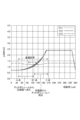
- FIG. 10 is a graph showing the change in pressure inside the first cylinder chamber 130S (graph G11) when injection operation is not performed (in other words, when the on-off valve connected to the injection pipe is closed) in a rotary compressor having the conventional injection mechanism shown in FIG. 8(b), in comparison with the change in pressure inside the first cylinder chamber (graph G12) in a rotary compressor assumed to not have an injection mechanism itself.
- the horizontal axis shows the rotation angle (0 to 360 degrees) of the first annular piston 125S when the vane position is set to 0 degrees in FIG. 9 and the first annular piston 125S is assumed to revolve clockwise around the inner circumference of the first cylinder 121S.
- the vertical axis shows the pressure Pd [MPaG] inside the first cylinder chamber 130S.
- Graph G11 shows the change in pressure inside the first cylinder chamber 130S in a rotary compressor 1 having the conventional injection mechanism shown in FIG. 8(b).
- Graph G12 shows the change in pressure inside the first cylinder chamber when it is assumed that the conventional rotary compressor does not have an injection mechanism.
- Graph G13 shows the change in pressure inside the injection pipe 141.
- FIG. 11 shows the rotation cycle of the first annular piston 125S inside the first cylinder chamber 130S when injection operation is not performed.
- FIG. 11(a) illustrates the state of the annular piston 125S when the rotation angle of the first annular piston 125S is about 40 degrees (point A).
- FIG. 11(b) illustrates the state of the annular piston 125S when the rotation angle of the first annular piston 125S is about 70 degrees (point B2).
- FIG. 11(c) illustrates the state of the annular piston 125S when the rotation angle of the first annular piston 125S is about 200 degrees (point C).
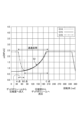
- FIG. 12 is a graph showing the change in pressure inside the first cylinder chamber 130S (graph G14) when injection operation is not performed (in other words, when the on-off valve connected to the injection pipe is closed) in the rotary compressor 1 having the injection mechanism of the embodiment shown in FIG. 8(a) in comparison with the change in pressure inside the first cylinder chamber (graph G15) in a rotary compressor assumed to not have the injection mechanism itself.
- the horizontal axis shows the rotation angle (0 to 360 degrees) of the first annular piston 125S when the vane position is set to 0 degrees in FIG. 11 and the first annular piston 125S is assumed to revolve clockwise around the inner circumference of the first cylinder 121S.
- FIG. 13 is a partial vertical cross-sectional view showing the compression section of the rotary compressor 1 according to the first modification.
- the holding tube 142 may be provided with a holding tube tip 142a that corresponds to the first step portion (first tapered portion) 304 provided in the injection hole 300.
- the holding tube 142 when the holding tube 142 is inserted and fixed into the injection hole 300, it is possible to eliminate the gap between the holding tube tip 142a and the first step portion (first tapered portion) 304, thereby preventing refrigerant leakage.
- FIG. 14 is a partial vertical cross-sectional view showing the compression section of the rotary compressor 1 according to the second modification.
- the holding tube 142 may be configured to hold the outer circumference of the injection tube 141 inserted into the injection introduction tube 144, which introduces the liquid refrigerant branched off from the outlet side of the condenser or after passing through the pressure reducing means to the injection hole 300, and the injection tube 141.
- the liquid refrigerant may be transported up to the injection hole 300 using the injection introduction tube 144, and an injection tube 141 formed to be thinner (for example, with an outer diameter R2 of 4 mm or less) may be used at the injection hole 300.
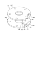
- Figure 15 is an exploded perspective view of the intermediate partition plate 140.
- the intermediate partition plate 140 may be divided into two, a lower intermediate partition plate 140S and an upper intermediate partition plate 140T, in the axial direction (the vertical direction in the figure) with the injection hole 300 as the boundary.
- the injection tube 141 connected to the holding tube 142 is placed on one of the intermediate partition plates (e.g., the lower intermediate partition plate 140S) that has the configuration for the injection hole 300. This allows the placement of the injection tube 141 inside the injection hole 300 to be visually confirmed.
- the other intermediate partition plate e.g., the upper intermediate partition plate 140T
- the intermediate partition plate 140 having the injection mechanism can be formed with high precision.
- the volume inside the capillary (dead volume DV10) is 0.18 cc.
- the volume inside the capillary in the conventional configuration (see dead volume DV2 in Figure 8 (b)) is 5.8 cc, the dead volume of the conventional configuration is 32.2 times that of this embodiment.
- a dead volume DV11 occurs where the refrigerant leaks outside the injection tube 141, as shown in FIG. 12.
- the above gap is 50 ⁇ m or less, there is no need to consider the dead volume DV11 due to refrigerant leakage, but if the gap exceeds 50 ⁇ m, it is better to consider the dead volume DV11.
- the rotary compressor 1 is designed to be similar in shape, so the shape does not change significantly whether the size is increased or decreased. Therefore, if the above gap is greater than 50 ⁇ m, the overall dead volume will be 2 to 2.5 times larger than in this embodiment, regardless of the size (large or small) of the rotary compressor 1.
- the embodiments have been described above, the embodiments are not limited to the above content.
- the above-mentioned components include those that a person skilled in the art can easily imagine, those that are substantially the same, and those that are within the so-called equivalent range.
- the above-mentioned components can be combined as appropriate.
- at least one of various omissions, substitutions, and modifications of the components can be made without departing from the spirit of the embodiment.
- the injection hole 300 is formed in the intermediate partition plate 140 in the two-cylinder rotary compressor, but the injection hole 300 may be formed in at least one of the lower end plate 160S and the upper end plate 160T.
- the present invention may also be applied to a single-cylinder rotary compressor and a two-stage compression rotary compressor.
- the injection hole 300 to which the injection pipe 141 is fixed is provided in the lower end plate 160S or the upper end plate 160T.
- the cylinder chamber 130 (first cylinder chamber 130S) of the rotary compressor 1 is formed between the cylinder 121 (first cylinder 121S) and the annular piston 125 (first annular piston 125S), and the cylinder chamber 130 is partitioned into the suction chamber 131 (first suction chamber 131S) and the compression chamber 133 (first compression chamber 133S) by the vane 127 (first vane 127S).
- this is not limiting.
- the present invention may be applied to an oscillating rotary compressor in which the piston and the vane (blade) are integrally formed.
Landscapes
- Engineering & Computer Science (AREA)
- Mechanical Engineering (AREA)
- General Engineering & Computer Science (AREA)
- Applications Or Details Of Rotary Compressors (AREA)
Abstract
実施形態にかかるロータリ圧縮機は、冷媒を圧縮する圧縮部と、圧縮部を駆動するモータと、圧縮部とモータとを内部に収容する圧縮機本体容器と、を備える。圧縮部は、内部にシリンダ室を形成するシリンダと、シリンダの内周側で公転するピストンと、シリンダの端部を閉塞する端板と、を有する。端板には、シリンダ室に連通し、冷媒を導通するインジェクション管が挿通可能なインジェクション孔が形成される。インジェクション孔には、インジェクション管の外周を保持する保持管を介してインジェクション管が固定される。
Description
本発明の実施形態は、ロータリ圧縮機に関する。
ロータリ圧縮機としては、圧縮機本体容器の内部に、冷媒を圧縮する圧縮部と、圧縮部を駆動するモータとが配置されたロータリ圧縮機が知られている。このロータリ圧縮機は、例えば、冷凍サイクル装置に搭載される。
冷凍サイクル装置に搭載される圧縮機においては、凝縮された液冷媒の一部を分岐させ、この分岐させた液冷媒を圧縮機のシリンダ室に注入(インジェクション)する、液インジェクション方式の従来技術が知られている。
液インジェクション方式の圧縮機では、凝縮器出口から分岐させたインジェクション用の通路の途中に開閉弁を設けることで、インジェクションを行う(インジェクション運転を行う)か否かを切り換えることが可能となる。しかしながら、この圧縮機では、インジェクション運転を行わないとき、インジョクション用の通路に設けられた開閉弁からシリンダ室までの空間が、デッドボリューム(死容積)となってしまう。このため、圧縮した冷媒が再度膨張してしまうことで圧縮効率を低下させるという問題がある。
特許文献1に記載されるロータリ圧縮機では、仕切板の径方向に伸びるインジェクション通路にスライド弁を設け、シリンダ室に連通するインジェクションポートを開くときにはスライド弁がインジェクション通路内に位置しないようにする。一方でインジェクションポートを閉じるときには、スライド弁をインジェクションポートの位置に配置することでインジェクション通路に冷媒が逆流しないようにして、インジェクション運転を行わない場合におけるデッドボリュームを減少させている。このようなスライド構造は、バネやスライド弁の構造が複雑になり、製造が難しいという問題がある。また、スライド構造の故障等でインジェクションが正常に行われなくなることにより圧縮機の信頼性が低下するおそれもある。
また、特許文献2に記載されるロータリ圧縮機において、インジェクション管自体を細く形成することが考えられる。しかしながら、単にインジェクション管を細くした場合、インジェクション管をインジェクション孔(横孔)に対して固定することが難しく、この場合も製造が難しいという問題がある。
開示の技術は、上記に鑑みてなされたものであって、製造を容易にしつつ、デッドボリュームを減少させることができるインジェクション機構を備えたロータリ圧縮機を提供することを目的とする。
本開示の実施形態にかかるロータリ圧縮機は、冷媒を圧縮する圧縮部と、圧縮部を駆動するモータと、圧縮部とモータとを内部に収容する圧縮機本体容器と、を備える。圧縮部は、内部にシリンダ室を形成するシリンダと、シリンダの内周側で公転するピストンと、シリンダの端部を閉塞する端板と、を有する。端板には、シリンダ室に連通し、冷媒を導通するインジェクション管が挿通可能なインジェクション孔が形成される。インジェクション孔には、インジェクション管の外周を保持する保持管を介してインジェクション管が固定される。
開示の技術によれば、製造を容易にしつつ、デッドボリュームを低減することができる。
以下、図面を参照して、実施形態にかかるロータリ圧縮機を説明する。実施形態において同一の機能を有する構成には同一の符号を付し、重複する説明は省略する。なお、以下の実施形態で説明するロータリ圧縮機は、一例を示すに過ぎず、実施形態を限定するものではない。また、以下の各実施形態は、矛盾しない範囲内で適宜組みあわせてもよい。
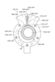
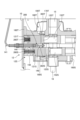
図1は、実施形態にかかるロータリ圧縮機の一例を示す縦断面図である。図2は、第1の圧縮部および第2の圧縮部の上からみた横断面図である。
図1に示すように、ロータリ圧縮機1は、密閉された縦置き円筒状の圧縮機筐体10の下部に配置された圧縮部12と、圧縮機筐体10の上部に配置され、回転軸15を介して圧縮部12を駆動するモータ11と、を備えている。
モータ11のステータ111は、円筒状に形成され、圧縮機筐体10の内周面に焼きばめされて固定されている。モータ11のロータ112は、円筒状のステータ111の内部に配置され、モータ11と圧縮部12とを機械的に接続する回転軸15に焼きばめされて固定されている。
圧縮部12は、第1の圧縮部12Sと、第1の圧縮部12Sと並列に配置され第1の圧縮部12Sの上側に積層された第2の圧縮部12Tと、を備えている。図2に示すように、第1の圧縮部12Sは、第1側方張出部122Sに、放射状に第1吸入孔135S、第1ベーン溝128Sが設けられた環状の第1シリンダ121Sを備えている。同様に、第2の圧縮部12Tは、第2側方張出部122Tに、放射状に第2吸入孔135T、第2ベーン溝128Tが設けられた環状の第2シリンダ121Tを備えている。
図2に示すように、第1シリンダ121Sおよび第2シリンダ121Tには、モータ11の回転軸15と同心に、円形の第1シリンダ内壁123Sおよび第2シリンダ内壁123Tが形成されている。第1シリンダ内壁123Sおよび第2シリンダ内壁123T内には、シリンダ内径よりも小さい外径の第1環状ピストン125Sおよび第2環状ピストン125Tが夫々配置されている。第1シリンダ内壁123Sと第1環状ピストン125Sとの間には、冷媒ガスを吸入し圧縮して吐出する第1シリンダ室130Sが形成される。同様に、第2シリンダ内壁123Tと第2環状ピストン125Tとの間には、冷媒ガスを吸入し圧縮して吐出する第2シリンダ室130Tが形成される。
第1シリンダ121Sには、第1シリンダ内壁123Sから径方向に、シリンダ高さ全域に亘る第1ベーン溝128Sが形成されている。同様に、第2シリンダ121Tには、第2シリンダ内壁123Tから径方向に、シリンダ高さ全域に亘る第2ベーン溝128Tが形成されている。第1ベーン溝128Sおよび第2ベーン溝128T内には、夫々平板状の第1ベーン127Sおよび第2ベーン127Tが、摺動自在に嵌合されている。
図2に示すように、第1ベーン溝128Sの奥部には、第1シリンダ121Sの外周部から第1ベーン溝128Sに連通するように第1スプリング穴124Sが形成されている。同様に、第2ベーン溝128Tの奥部には、第2シリンダ121Tの外周部から第2ベーン溝128Tに連通するように第2スプリング穴124Tが形成されている。第1スプリング穴124Sには、第1ベーン127Sの背面を押圧する第1ベーンスプリング260S(図3参照)が挿入されている。同様に、第2スプリング穴124Tには、第2ベーン127Tの背面を押圧する第2ベーンスプリング260T(図3参照)が挿入されている。
ロータリ圧縮機1の起動時は、第1ベーンスプリング260Sの反発力により、第1ベーン127Sが、第1ベーン溝128S内から第1シリンダ室130S内に突出する。同様に、ロータリ圧縮機1の起動時は、第2ベーンスプリング260Tの反発力により、第2ベーン127Tが、第2ベーン溝128T内から第2シリンダ室130T内に突出する。そして、第1ベーン127Sの先端が、第1環状ピストン125Sの外周面に当接する。同様に、第2ベーン127Tの先端が、第2環状ピストン125Tの外周面に当接する。このように当接した第1ベーン127Sにより、第1シリンダ室130Sが、第1吸入室131Sと、第1圧縮室133Sとに区画される。また、第2ベーン127Tにより、第2シリンダ室130Tが、第2吸入室131Tと、第2圧縮室133Tとに区画される。
また、第1及び第2シリンダ121S、121Tには、第1及び第2ベーン溝128S、128Tの奥部と圧縮機筐体10内とを、図1に示す開口部Rで連通している。この開口部Rより圧縮機筐体10内に圧縮された冷媒ガスを導入し、第1及び第2ベーン127S、127Tに、冷媒ガスの圧力により背圧をかける第1及び第2圧力導入路129S、129Tが形成されている。
第1及び第2シリンダ121S、121Tには、第1及び第2吸入室131S、131Tに外部から冷媒を吸入するために、第1及び第2吸入室131S、131Tと外部とを連通させる第1及び第2吸入孔135S、135Tが設けられている。
また、図1に示すように、第1シリンダ121Sと第2シリンダ121Tの間には、中間仕切板140が配置され、第1シリンダ121Sの第1シリンダ室130S(図2参照)と第2シリンダ121Tの第2シリンダ室130T(図2参照)とを区画、閉塞している。中間仕切板140は、第1シリンダ121Sの上端部と第2シリンダ121Tの下端部を閉塞している。すなわち、中間仕切板140は、シリンダの端部を閉塞する端板の一例である。
第1シリンダ121Sの下端部には、下端板160Sが配置され、第1シリンダ121Sの第1シリンダ室130Sを閉塞している。また、第2シリンダ121Tの上端部には、上端板160Tが配置され、第2シリンダ121Tの第2シリンダ室130Tを閉塞している。下端板160Sは、第1シリンダ121Sの下端部を閉塞し、上端板160Tは、第2シリンダ121Tの上端部を閉塞している。
下端板160Sには、副軸受部161Sが形成され、副軸受部161Sに、回転軸15の副軸部151が回転自在に支持されている。上端板160Tには、主軸受部161Tが形成され、主軸受部161Tに、回転軸15の主軸部153が回転自在に支持されている。
回転軸15は、互いに180°位相をずらして偏心させた第1偏心部152Sと第2偏心部152Tとを備える。第1偏心部152Sは、第1の圧縮部12Sの第1環状ピストン125Sに回転自在に嵌合している。第2偏心部152Tは、第2の圧縮部12Tの第2環状ピストン125Tに回転自在に嵌合している。
回転軸15が回転すると、第1及び第2環状ピストン125S、125Tが、第1及び第2シリンダ内壁123S、123Tに沿って第1及び第2シリンダ121S、121T内を図2の時計回りに公転する。この公転に追随して第1及び第2ベーン127S、127Tが往復運動する。この第1及び第2環状ピストン125S、125T及び第1及び第2ベーン127S、127Tの運動により、第1及び第2吸入室131S、131T及び第1及び第2圧縮室133S、133Tの容積が連続的に変化する。また、圧縮部12では、連続的に冷媒ガスを吸入し圧縮して吐出する。
図1に示すように、下端板160Sの下側には、下マフラーカバー170Sが配置され、下端板160Sとの間に下マフラー室180Sを形成している。そして、第1の圧縮部12Sは、下マフラー室180Sに開口している。すなわち、下端板160Sの第1ベーン127S近傍には、第1シリンダ121Sの第1圧縮室133Sと下マフラー室180Sとを連通する第1吐出孔190S(図2参照)が設けられる。第1吐出孔190Sには、圧縮された冷媒ガスの逆流を防止するリード弁型の第1吐出弁200Sが配置されている。
下マフラー室180Sは、環状に形成された1つの室であり、第1の圧縮部12Sの吐出側を、下端板160S、第1シリンダ121S、中間仕切板140、第2シリンダ121T及び上端板160Tを貫通する冷媒通路136(図2参照)を通して上マフラー室180T内に連通させる連通路の一部である。下マフラー室180Sは、吐出冷媒ガスの圧力脈動を低減させる。また、第1吐出弁200Sに重ねて、第1吐出弁200Sの撓み開弁量を制限するための第1吐出弁押え201Sが、第1吐出弁200Sとともにリベットにより固定されている。第1吐出孔190S、第1吐出弁200S及び第1吐出弁押え201Sは、下端板160Sの第1吐出弁部を構成している。
図1に示すように、上端板160Tの上側には、上マフラーカバー170Tが配置され、上端板160Tとの間に上マフラー室180Tを形成している。上端板160Tの第2ベーン127T近傍には、第2シリンダ121Tの第2圧縮室133Tと上マフラー室180Tとを連通する第2吐出孔190T(図2参照)が設けられている。第2吐出孔190Tには、圧縮された冷媒ガスの逆流を防止するリード弁型の第2吐出弁200Tが配置されている。また、第2吐出弁200Tに重ねて、第2吐出弁200Tの撓み開弁量を制限するための第2吐出弁押え201Tが、第2吐出弁200Tとともにリベットにより固定されている。上マフラー室180Tは、吐出冷媒の圧力脈動を低減させる。第2吐出孔190T、第2吐出弁200T及び第2吐出弁押え201Tは、上端板160Tの第2吐出弁部を構成している。
第1シリンダ121S、下端板160S、下マフラーカバー170S、第2シリンダ121T、上端板160T、上マフラーカバー170T及び中間仕切板140は、複数の通しボルト175等により一体に締結されている。通しボルト175等により一体に締結された圧縮部12のうち、上端板160Tの外周部が、圧縮機筐体10にスポット溶接により固着され、圧縮部12を圧縮機筐体10に固定している。
円筒状の圧縮機筐体10の外周壁には、軸方向に離間して下部から順に、第1貫通孔101および第2貫通孔102が、第1吸入管104および第2吸入管105を通すために設けられている。また、圧縮機筐体10の外側部には、独立した円筒状の密閉容器からなるアキュムレータ25が、アキュムホルダ252及びアキュムバンド253により保持されている。
アキュムレータ25の天部中心には、冷媒回路の蒸発器に接続するシステム接続管255が接続されている。アキュムレータ25の底部に設けられた底部貫通孔257には、一端がアキュムレータ25の内部上方まで延設され、他端が、第1吸入管104および第2吸入管105の他端に接続される第1低圧連絡管31Sおよび第2低圧連絡管31Tが固着されている。
冷媒回路の低圧冷媒をアキュムレータ25を介して第1の圧縮部12Sに導く第1低圧連絡管31Sは、吸入部としての第1吸入管104を介して第1シリンダ121Sの第1吸入孔135S(図2参照)に接続されている。また、冷媒回路の低圧冷媒をアキュムレータ25を介して第2の圧縮部12Tに導く第2低圧連絡管31Tは、吸入部としての第2吸入管105を介して第2シリンダ121Tの第2吸入孔135T(図2参照)に接続されている。すなわち、第1吸入孔135Sおよび第2吸入孔135Tは、冷媒回路の蒸発器に並列に接続されている。
圧縮機筐体10の天部には、冷媒回路と接続し高圧冷媒ガスを冷媒回路の凝縮器側に吐出する吐出部としての吐出管107が接続されている。すなわち、第1吐出孔190Sおよび第2吐出孔190Tは、冷媒回路の凝縮器に接続されている。
圧縮機筐体10内には、およそ第2シリンダ121Tの高さまで潤滑油が封入されている。また、潤滑油は、回転軸15の下部に挿入される図示しないポンプ羽根により、回転軸15の下端部に取付けられた給油パイプ16から吸上げられ、圧縮部12を循環する。これにより、潤滑油は、摺動部品の潤滑を行なうとともに、圧縮部12の微小隙間のシールをする。
図3は、実施形態にかかるロータリ圧縮機1の圧縮部12を示す部分縦断面図である。図3に示すように、中間仕切板140には、連通孔302Sにより第1シリンダ室130Sに連通するとともに、連通孔302Tにより第2シリンダ室130Tに連通し、冷媒を供給するインジェクション管141が挿通可能なインジェクション孔300が形成されている。このインジェクション孔300には、インジェクション管141の外周を保持する保持管142を介してインジェクション管141が固定されている。
ヒートポンプを用いた冷凍サイクル装置は、近年、外気温度の低い寒冷地でも普及が進んでいる。外気温度が低い環境下で蒸発器が使用されている場合、圧縮部12に吸入される冷媒の密度が下がり、十分な暖房能力を得ることが困難になる。このため、凝縮器の出口側や減圧手段通過後の液冷媒の一部を分岐させ、分岐させた液冷媒をインジェクション管141を介して圧縮部12の第1シリンダ室130Sおよび第2シリンダ室130Tに注入させること、すなわち液インジェクション(気体の冷媒を注入するガスインジェクションであってもよい)を行う。
この液インジェクションを行うことで、冷媒の循環量を増やして暖房能力を向上させることができる。また、暖房時に外気温度が低い場合には、圧縮比が大きい条件での運転となるため、第1シリンダ室130Sおよび第2シリンダ室130T内の冷媒温度が高くなるが、液インジェクションを行うことで、液冷媒の蒸発潜熱でシリンダ室内を冷却することにより冷媒温度を下げることができる。
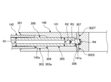
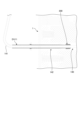
図4~図7は、中間仕切板140のインジェクション孔300を示す部分断面図である。具体的には、図4は、インジェクション管141および保持管142をインジェクション孔300に挿入する前の部分断面図である。図5は、保持管142をインジェクション孔300に挿入した後の部分断面図である。図6は、インジェクション管141および保持管142をインジェクション孔300に挿入した後の部分断面図である。図7は、インジェクション管先端141aを封止部材143で封止する構成を例示する部分断面図である。
図4に示すように、インジェクション孔300は、中間仕切板140の外側の開口部301から奥の連通孔302S、302Tに向かって内径が徐々に小さくなる構造となっている。具体的には、インジェクション孔300は、開口部301から大径部303、第1の段差部(第1のテーパ部)304、第1の小径部305、第2の段差部(第2のテーパ部)306、第2の小径部307の順に内径が小さくなる。そして、第2の小径部307には、第1シリンダ室130Sと連通する連通孔302Sおよび第2シリンダ室130Tと連通する連通孔302Tが設けられている。
大径部303は、開口部301から奥の第1の段差部(第1のテーパ部)304に向かって連続して形成されている。図5に示すように、大径部303は、開口部301からの内径が保持管142の外径よりも若干大きく、保持管142を挿通可能な構成となっている。
図4に示すように、大径部303は、例えば、奥に向かって内径が徐々に小さくなる緩やかなテーパ形状である。なお、大径部303は、開口部301側から奥の第1の段差部(第1のテーパ部)304まで内径が変化しない円筒形状であってもよい。また、大径部303は、奥に向かって内径が徐々に小さくなり、例えば、第1のテーパ部304の位置で第1の小径部305と同程度の内径となるような形状、すなわち、大径部303の全体がテーパ形状となることで第1の段差部を備えない形状となっていてもよい。
大径部303から第1の小径部305に亘る第1の段差部(第1のテーパ部)304は、奥に向かって連続的に小径となるようにテーパ形状になっている。すなわち、第1の小径部305は、大径部303から第1の段差部(第1のテーパ部)304を介して連続的に形成されており、大径部303よりも小径であるとともに、大径部303より連通孔302S、302T側に位置している。なお、大径部303と第1の小径部305の間に位置する第1の段差部304は、テーパ形状に限られず、例えばインジェクション管141が伸びる方向に対して垂直な段差によって形成されてもよい。
第1の小径部305は、手前の第1の段差部(第1のテーパ部)304から奥の第2の段差部(第2のテーパ部)306に向かって連続して形成されている。例えば、第1の小径部305は、第1の段差部(第1のテーパ部)304側から奥の第2の段差部(第2のテーパ部)306まで内径が変化しない円筒形状である。第1の小径部305の内径は、インジェクション管141の外径よりも若干大きく、インジェクション管141を挿通可能な構成となっている。
第1の小径部305から第2の小径部307に亘る第2の段差部(第2のテーパ部)306は、奥に向かって徐々に小径となるようにテーパ形状になっている。すなわち、第2の小径部307は、第1の小径部305より小径であるとともに、第1の小径部305から第2の段差部(第2のテーパ部)306を介して連続的に形成されている。なお、第1の小径部305と第2の小径部307の間に位置する第2の段差部306は、テーパ形状に限られず、例えばインジェクション管141が伸びる方向に対して垂直な段差によって形成されてもよい。
図6に示すように、保持管142は、インジェクション孔300の開口部301より差し込まれ、例えば、インジェクション孔300に形成された孔側テーパ部で、固定される。保持管142が固定される孔側テーパ部は、大径部303の内周面自体が緩やかなテーパ形状に形成されることで形成されてもよい。この場合は、図5~6に示すように、大径部303に孔側テーパ部303aが形成され、保持管先端142aが、緩やかなテーパ形状である大径部303の途中で固定される。あるいは、保持管142が固定される孔側テーパ部は、第1の段差部(第1のテーパ部)304であってもよい。この場合は、図示しないが、保持管先端142aが、第1の段差部(第1のテーパ部)304に突き当たったところで、固定される。このように、保持管142は、インジェクション孔300に固定された際に、保持管先端142aが大径部303に位置するとともに、孔側テーパ部(303a、304)によって、差し込まれた際の保持管先端142aの位置決めが行われる。この保持管142は、内径R1がインジェクション管141の外径R2以上であり、例えば銅管などを適用できる。
インジェクション管141は、保持管142に差し込むことで保持管142の内壁面で保持される部分の全体に亘って保持管142より細く(R1>R2)形成されている。このため、インジェクション管141は、インジェクション孔300に固定された保持管142を介して第1の小径部305に差し込まれ、例えば、インジェクション管先端141aが第2の段差部(第2のテーパ部)306に突き当たったところ固定される。
このように、インジェクション管141は、保持管142を介してインジェクション孔300に固定された際に、インジェクション管先端141aが第1の小径部305に位置するとともに、第2の段差部(第2のテーパ部)306によって、差し込まれた際のインジェクション管先端141aの位置決めが行われる。このような位置決めにより、インジェクション管141から冷媒が吐出する出口部分(インジェクション管先端141a)は、第2の小径部307の入口部分に位置することとなる。すなわち、第2の小径部307は、インジェクション管141がインジェクション孔300に固定された際に、インジェクション管141の出口から連続するような構成となる。
また、インジェクション管141の内径R3は、第2の小径部307の内径R4よりも小さい(R4>R3)ものとする。これにより、ロータリ圧縮機1では、インジェクション管141の出口から、滞ることなく、第2の小径部307内に冷媒を吐出させることができる。
また、図7に示すように、インジェクション管先端141aには、インジェクション孔300における第1の小径部305の内周面と、インジェクション管141の外周面との間を塞ぐように、封止部材143を設けてもよい。この封止部材143は、例えば、弾性のあるゴム材のO-リング、弾性のないテフロン(登録商標)製のガスケットなどを適用できる。このように、封止部材143によりインジェクション孔300における第1の小径部305の内周面と、インジェクション管141の外周面との間の隙間を塞ぐことで、中間仕切板140より第2の小径部307側に吐出した冷媒が外に漏れ出ることを抑止できる。
ここで、封止部材143の有無に関わらず、インジェクション孔300の第1の小径部305の内周面と、インジェクション管先端141aの外周面と、の間に形成される隙間の寸法は、50μm以下であることが好ましい。このように、ロータリ圧縮機1は、第1の小径部305の内周面と、インジェクション管先端141aの外周面との隙間の寸法を50μm以下とすることで、インジェクション管先端141aより注入される冷媒が上記の隙間から漏れ出ることを抑止できる。
このインジェクション管141としては、例えば、外径R2が4mm以下であり、内径R3が3mm程度の銅管などを適用できる。これにより、実施形態のロータリ圧縮機1では、インジェクション管141がその上流側に接続される配管よりも内径が小さいキャピラリーチューブとして機能し、インジェクション管141の内部を通過する冷媒の圧力を降下させることができる。
図8は、ロータリ圧縮機1のインジェクション機構におけるデッドボリュームの従来例との比較を説明する説明図である。具体的には、図8(a)が実施形態のロータリ圧縮機1のインジェクション機構におけるデッドボリュームDV1を例示しており、図8(b)従来のロータリ圧縮機の中間仕切板500におけるインジェクション機構のデッドボリュームDV2を例示している。
図8(a)に示すように、ロータリ圧縮機1の中間仕切板140には、連通孔302S、302Tを介して第1シリンダ室130Sおよび第2シリンダ室130Tに連通し、冷媒を供給するインジェクション管141が挿通可能なインジェクション孔300が形成されている。そして、インジェクション孔300には、インジェクション管141の外周を保持する保持管142を介してインジェクション管141が固定される。
これにより、ロータリ圧縮機1では、インジェクション運転を行わない場合のデッドボリュームとなる容積が少なくするように細く(例えば外径R2を4mm以下に)形成したインジェクション管141を、保持管142を介して容易にインジェクション孔300内の連通孔302S、302T近傍に設置することができる。このため、図8(a)に示す実施形態のロータリ圧縮機1のデッドボリュームDV1と、図8(b)に示すインジェクション管141がインジェクション孔300の内部まで差し込まれていない従来例のロータリ圧縮機1のデッドボリュームDV2とを比較しても明らかなように、実施形態のロータリ圧縮機1では、インジェクション運転を行わない場合におけるデッドボリュームを減少させることができる。
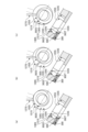
図9(a)~図9(c)は、従来例のインジェクション機構を備えたロータリ圧縮機における、環状ピストン125の回転サイクルを示す径方向断面図および回転軸15に直交する方向の断面図である。図9に示すように、中間仕切板500には、インジェクション孔300に連通する連通孔302Sおよび302Tが形成されており、インジェクション運転を行う場合には、インジェクション管141から吐出された液冷媒が、連通孔302Sを介して第1シリンダ室130Sに導入されるとともに、連通孔302Tを介して第2シリンダ室130Tに導入される。図9では、インジェクション運転を行わない場合での第1シリンダ室130Sの内部での第1環状ピストン125Sの回転サイクルを示している。なお、図9(a)は、第1環状ピストン125Sの回転角度が約40度のタイミング(A点)での環状ピストン125Sの状態を例示している。図9(b)は、第1環状ピストン125Sの回転角度が約130度のタイミング(B1点)での環状ピストン125Sの状態を例示している。図9(c)は、第1環状ピストン125Sの回転角度が約200度のタイミング(C点)での環状ピストン125Sの状態を例示している。
図10は、図8(b)に示す従来例のインジェクション機構を備えたロータリ圧縮機における、インジェクション運転を行わない場合(言い換えれば、インジェクション管に繋がる開閉弁を閉じた場合)での、第1シリンダ室130Sの内部の圧力の変化(グラフG11)を、インジェクション機構自体を備えないと仮定したロータリ圧縮機における第1シリンダ室の内部の圧力の変化(グラフG12)と対比して示すグラフである。横軸は、図9において、ベーンの位置を0度とし、第1環状ピストン125Sが第1シリンダ121Sの内周側を時計回りに公転すると仮定したときの、第1環状ピストン125Sの回転角度(0~360度)を示す。縦軸は、第1シリンダ室130Sの内部の圧力Pd[MPaG]を示す。グラフG11は、図8(b)に示す従来例のインジェクション機構を備えたロータリ圧縮機1における、第1シリンダ室130Sの内部の圧力の変化を示す。グラフG12は、従来例のロータリ圧縮機がインジェクション機構自体を備えないと仮定したときにおける、第1シリンダ室の内部の圧力の変化を示す。グラフG13は、インジェクション管141の内部の圧力の変化を示す。
図9(a)~図9(c)に示すように、従来例のインジェクション機構を備えたロータリ圧縮機は、第1環状ピストン125Sの回転角度が0度のタイミング(図9(a)と図9(c)の間)では、連通孔302Sが第1環状ピストン125Sによって塞がれており、デッドボリュームDV2から第1シリンダ室130Sへの気体冷媒の流入は起こらない。
次に、従来例のインジェクション機構を備えたロータリ圧縮機は、図9(a)に示すように、第1環状ピストン125Sの回転角度が約40度のタイミング(A点)で、第1環状ピストン125Sに塞がれていた連通孔302Sが開放され、図8(b)で示したデッドボリュームDV2と、第1シリンダ室130Sとが連通する。このとき、デッドボリュームDV2に閉じ込められていた高圧の気体冷媒が連通孔302Sを介して第1シリンダ室130Sへ流入する。これにより、図10に示すように、A点以降では、従来例のインジェクション機構を備えたロータリ圧縮機における第1シリンダ室130Sの内部の圧力(グラフG11)が、インジェクション機構を備えないと仮定した比較例のロータリ圧縮機における第1シリンダ室の内部の圧力(グラフG12)に比べて、上昇してしまう。その結果、従来例のインジェクション機構を備えたロータリ圧縮機は、第1シリンダ室130Sの内部の圧力が高いことにより、第1環状ピストン125Sを回転させるのに必要な動力が、比較例に比べて増加してしまい、ロータリ圧縮機1の動作のエネルギー効率が低下してしまう。
図9(b)に示すように、従来例のインジェクション機構を備えたロータリ圧縮機は、第1環状ピストン125Sの回転角度が約130度のタイミング(B1点)で、今度は逆に、第1シリンダ室130Sの内部で圧縮された気体冷媒の一部が、デッドボリュームDV2側へと逆流し始めるようになる。なお、ある回の回転サイクルで第1シリンダ室130SからデッドボリュームDV2へ逆流した気体冷媒は、その次の回の回転サイクルでデッドボリュームDV2から第1シリンダ室130Sの内部へと流入する気体冷媒となる。
図9(c)に示すように、従来例のインジェクション機構を備えたロータリ圧縮機は、第1環状ピストン125Sの回転角度が約200度のタイミング(C点)では、第1シリンダ室130Sとインジェクション管141とを連通する連通孔302Sが、再び第1環状ピストン125Sによって塞がれる。この時点で、デッドボリュームDV2と第1シリンダ室130Sとの間での、気体冷媒の相互の流入が終了する。
以上のように、図8(b)に示す従来例のインジェクション機構を備えたロータリ圧縮機では、図9および図10に示すように、第1環状ピストン125Sの回転角度が約40度~130度の間、デッドボリュームDV2から第1シリンダ室130Sへの気体冷媒の流入が起き、第1環状ピストン125Sの回転角度が約130度~200度の間、今度は第1シリンダ室130SからデッドボリュームDV2への気体冷媒の流出が起きている。その結果、従来例のインジェクション機構を備えたロータリ圧縮機は、第1環状ピストン125Sを1回転させるのに必要な動力が、インジェクション機構を備えないと仮定した比較例に比べて、図10に示す面積S1の分だけ増加する。その結果、従来例のインジェクション機構を備えたロータリ圧縮機は、圧縮機としての動作のエネルギー効率が低下してしまう。
次に、実施形態のインジェクション機構を備えたロータリ圧縮機1の場合について説明する。図11(a)~図11(c)は、実施形態のインジェクション機構を備えたロータリ圧縮機1における、環状ピストン125の回転サイクルを示す径方向断面図および回転軸15に直交する方向の断面図である。図11に示すように、中間仕切板140には、インジェクション孔300に連通する連通孔302Sおよび302Tが形成されており、インジェクション運転を行う場合には、インジェクション管141から吐出された液冷媒が、連通孔302Sを介して第1シリンダ室130Sに導入されるとともに、連通孔302Tを介して第2シリンダ室130Tに導入される。図11では、インジェクション運転を行わない場合での第1シリンダ室130Sの内部での第1環状ピストン125Sの回転サイクルを示している。なお、図11(a)は、第1環状ピストン125Sの回転角度が約40度のタイミング(A点)での環状ピストン125Sの状態を例示している。図11(b)は、第1環状ピストン125Sの回転角度が約70度のタイミング(B2点)での環状ピストン125Sの状態を例示している。図11(c)は、第1環状ピストン125Sの回転角度が約200度のタイミング(C点)での環状ピストン125Sの状態を例示している。
図12は、図8(a)に示す実施形態のインジェクション機構を備えたロータリ圧縮機1における、インジェクション運転を行わない場合(言い換えれば、インジェクション管に繋がる開閉弁を閉じた場合)での、第1シリンダ室130Sの内部の圧力の変化(グラフG14)を、インジェクション機構自体を備えないと仮定したロータリ圧縮機における第1シリンダ室の内部の圧力の変化(グラフG15)と対比して示すグラフである。横軸は、図11において、ベーンの位置を0度とし、第1環状ピストン125Sが第1シリンダ121Sの内周側を時計回りに公転すると仮定したときの、第1環状ピストン125Sの回転角度(0~360度)を示す。縦軸は、第1シリンダ室130Sの内部の圧力Pd[MPaG]を示す。グラフG14は、図8(a)に示す実施形態のインジェクション機構を備えたロータリ圧縮機1における、第1シリンダ室130Sの内部の圧力の変化を示す。グラフG15は、実施形態のロータリ圧縮機がインジェクション機構自体を備えないと仮定したときにおける、第1シリンダ室の内部の圧力の変化を示す。グラフG16は、インジェクション管141の内部の圧力の変化を示す。
図11(a)~(c)示すように、実施形態のインジェクション機構を備えたロータリ圧縮機1は、第1環状ピストン125Sの回転角度が0度のタイミング(図11(a)~図11(c)の間)では、連通孔302Sが第1環状ピストン125Sによって塞がれており、デッドボリュームDV1から第1シリンダ室130Sへの気体冷媒の流入は起こらない。
次に、実施形態のインジェクション機構を備えたロータリ圧縮機1は、図11(a)に示すように、第1環状ピストン125Sの回転角度が約40度のタイミング(A点)で、第1環状ピストン125Sに塞がれていた連通孔302Sが開放され、図8(a)で示したデッドボリュームDV1と、第1シリンダ室130Sとが連通する。このとき、デッドボリュームDV1に閉じ込められていた高圧の気体冷媒が連通孔302Sを介して第1シリンダ室130Sへ流入する。しかしながら、図8(a)および図12に示すように、実施形態のインジェクション機構はデッドボリュームDV1の体積が小さいので、デッドボリュームDV1と第1シリンダ室130Sとが連通するA点以降でも、実施形態のインジェクション機構を備えたロータリ圧縮機1における第1シリンダ室130Sの内部の圧力(グラフG14)は、実施形態のロータリ圧縮機1がインジェクション機構を備えないと仮定した場合における第1シリンダ室の内部の圧力(グラフG15)に比べても、殆ど増大しない。そのため、実施形態のインジェクション機構を備えたロータリ圧縮機1は、第1シリンダ室130Sの内部の圧力が増大するのを抑制できる。その結果、実施形態のインジェクション機構を備えたロータリ圧縮機1は、第1環状ピストン125Sを回転させるのに必要な動力が増加するのを抑制でき、ロータリ圧縮機1の動作のエネルギー効率が低下するのを抑制できる。
図11(b)に示すように、実施形態のインジェクション機構を備えたロータリ圧縮機1は、第1環状ピストン125Sの回転角度が約70度のタイミング(B2点)で、第1シリンダ室130Sの内部で圧縮された気体冷媒の一部が、デッドボリュームDV1側へと逆流し始める。しかし、実施形態のインジェクション機構はデッドボリュームDV1の体積が小さいので、第1シリンダ室130SからデッドボリュームDV1への逆流の影響が小さい。そのため、図12に示すように、B2点以降でも、実施形態のインジェクション機構を備えたロータリ圧縮機1における第1シリンダ室130Sの内部の圧力(グラフG14)は、実施形態のロータリ圧縮機1がインジェクション機構を備えないと仮定した場合における第1シリンダ室の内部の圧力(グラフG15)に比べて、殆ど増大しない。
図11(c)に示すように、実施形態のインジェクション機構を備えたロータリ圧縮機1は、第1環状ピストン125Sの回転角度が約200度のタイミング(C点)では、第1シリンダ室130Sとインジェクション管141とを連通する連通孔302Sが、再び第1環状ピストン125Sによって塞がれる。この時点で、デッドボリュームDV1と第1シリンダ室130Sとの間での、気体冷媒の相互の流入が終了する。
以上のように、図8(a)に示す実施形態のインジェクション機構を備えたロータリ圧縮機1では、図11および図12に示すように、第1環状ピストン125Sの回転角度が約40度~70度の間、デッドボリュームDV1から第1シリンダ室130Sへの気体冷媒の流入が起き、第1環状ピストン125Sの回転角度が約70度~200度の間、今度は第1シリンダ室130SからデッドボリュームDV1への気体冷媒の流出が起きる。その結果、実施形態のインジェクション機構を備えたロータリ圧縮機1は、第1環状ピストン125Sを1回転させるのに必要な動力が、実施形態のロータリ圧縮機がインジェクション機構を備えないと仮定した場合に比べて、図12に示す面積S2の分だけ増加する。しかしながら、実施形態のインジェクション機構はデッドボリュームDV1が小さいので、実施形態のインジェクション機構を備えたロータリ圧縮機1は、圧縮機としての動作のエネルギー効率の低下が殆どない。
図13は、変形例1にかかるロータリ圧縮機1の圧縮部を示す部分縦断面図である。図13に示すように、保持管142には、インジェクション孔300に設けられた第1の段差部(第1のテーパ部)304に対応する保持管先端142aが設けられていてもよい。これにより、変形例1にかかるロータリ圧縮機1では、保持管142をインジェクション孔300内に差し込んで固定する場合、保持管先端142aと第1の段差部(第1のテーパ部)304との間の隙間をなくすことができ、冷媒の漏れを防ぐことができる。
図14は、変形例2にかかるロータリ圧縮機1の圧縮部を示す部分縦断面図である。図14に示すように、保持管142は、凝縮器の出口側や減圧手段通過後に分岐させた液冷媒をインジェクション孔300まで導入するインジェクション導入管144と、インジェクション管141とについて、インジェクション導入管144にインジェクション管141が差し込まれた状態の外周を保持する構成であってもよい。変形例2にかかるロータリ圧縮機1のように、インジェクション孔300まではインジェクション導入管144を用いて液冷媒を運び、インジェクション孔300のところでより細く(例えば外径R2を4mm以下)形成したインジェクション管141を用いてもよい。
図15は、中間仕切板140の分解斜視図である。図15に示すように、中間仕切板140は、軸方向(図の上下方向)でインジェクション孔300を境に、下中間仕切板140Sと上中間仕切板140Tの2つに分割される構成であってもよい。
これにより、下中間仕切板140Sでは、インジェクション孔300にかかる構成(開口部301、大径部303、第1の段差部(第1のテーパ部)304、第1の小径部305、第2の段差部(第2のテーパ部)306および第2の小径部307)の下部分を加工精度の高いNCフライス盤などの工作機械で形成することができる。同様に、上中間仕切板140Tでは、インジェクション孔300にかかる構成の上部分を加工精度の高いNCフライス盤などで形成することができる。
中間仕切板140を形成する場合、インジェクション孔300にかかる構成を形成した一方の中間仕切板(例えば下中間仕切板140S)に保持管142と繋げたインジェクション管141を配置する。これにより、インジェクション孔300内のインジェクション管141の配置状態などを目視で確認することができる。ついで、インジェクション管141を配置した一方の中間仕切板に、他方の中間仕切板(例えば上中間仕切板140T)が接合される。このようにして、インジョクション機構を有する中間仕切板140を精度よく形成することができる。
図16は、接続弁からのデッドボリュームを説明する説明図である。図17は、図16の点線部分の拡大図である。
図16において、接続弁位置P1は、凝縮器の出口側や減圧手段通過後に分岐させた液冷媒をインジェクション機構へと接続させる接続弁の位置とする。したがって、図16に示すように、接続弁位置P1から連通孔302S、302Tまでのインジェクション管141(キャピラリー)の容積がデッドボリュームDV10に相当する。
ここで、本実施形態にかかるキャピラリーの内径を約1mm、接続弁位置P1から連通孔302S、302Tまでのキャピラリーの長さを160mmと仮定すると、キャピラリー内部の容積(デッドボリュームDV10)は、0.18ccとなる。従来の構成(図8(b)のデッドボリュームDV2参照)におけるキャピラリー内部の容積を5.8ccと仮定した場合、本実施形態に対して従来はデッドボリュームが32.2倍にもなる。
また、インジェクション孔300の第1の小径部305の内周面と、インジェクション管先端141aの外周面と、の間に形成される隙間が大きくなる場合は、図12に示すように、インジェクション管141の外側に冷媒が漏れる部分のデッドボリュームDV11が生じる。例えば、上記の隙間が50μm以下であれば、冷媒漏れによるデッドボリュームDV11を考慮する必要はないが、隙間が50μmを超える場合はデッドボリュームDV11を考慮したほうがよい。
このデッドボリュームDV11については、例えば0.42cc程度を見積もることができる。したがって、上記の隙間が50μmよりも大きい場合は、デッドボリュームDV11により、デッドボリュームDV11が生じない本実施形態と比較して、全体のデッドボリュームの大きさが0.42/0.18=2.33倍となる。
ロータリ圧縮機1の設計は相似形なので、サイズが大型化しても小型化しても形状が大きく変化することはない。したがって、上記の隙間が50μmよりも大きい場合は、ロータリ圧縮機1のサイズ(大型化または小型化)に関係なく、本実施形態よりも全体でのデッドボリュームの大きさが2~2.5倍となる。
以上、実施形態を説明したが、前述した内容により実施形態が限定されるものではない。また、前述した構成要素には、当業者が容易に想定できるもの、実質的に同一のもの、いわゆる均等の範囲のものが含まれる。さらに、前述した構成要素は適宜組み合わせることが可能である。さらに、実施形態の要旨を逸脱しない範囲で構成要素の種々の省略、置換及び変更のうち少なくとも1つを行うことができる。
なお、前述した実施形態では、2シリンダ式ロータリ圧縮機において、インジェクション孔300が中間仕切板140に形成される場合を例示したが、インジェクション孔300は下端板160Sおよび上端板160Tの少なくとも一方に設けられてもよい。
また、前述した実施形態では、2シリンダ式ロータリ圧縮機について説明したが、単シリンダ式ロータリ圧縮機及び2段圧縮式ロータリ圧縮機等に適用してもよい。例えば、単シリンダ式ロータリ圧縮機の場合、インジェクション管141が固定されるインジェクション孔300は、下端板160Sまたは上端板160Tに設けられる。
なお、前述した実施形態では、ロータリ圧縮機1のシリンダ室130(第1シリンダ室130S)がシリンダ121(第1シリンダ121S)と環状ピストン125(第1環状ピストン125S)との間に形成され、シリンダ室130がベーン127(第1ベーン127S)により吸入室131(第1吸入室131S)と圧縮室133(第1圧縮室133S)とに区画される場合を例示したが、これに限定されない。例えば、図示しないが、ピストンとベーン(ブレード)とが一体に形成された、揺動型のロータリ圧縮機に適用されてもよい。
1…ロータリ圧縮機
10…圧縮機筐体
11…モータ
12…圧縮部
12S…第1の圧縮部
12T…第2の圧縮部
15…回転軸
16…給油パイプ
25…アキュムレータ
31S…第1低圧連絡管
31T…第2低圧連絡管
101…第1貫通孔
102…第2貫通孔
104…第1吸入管
105…第2吸入管
107…吐出管
111…ステータ
112…ロータ
121S…第1シリンダ
121T…第2シリンダ
122S…第1側方張出部
122T…第2側方張出部
123S…第1シリンダ内壁
123T…第2シリンダ内壁
124S…第1スプリング穴
124T…第2スプリング穴
125S…第1環状ピストン
125T…第2環状ピストン
127S…第1ベーン
127T…第2ベーン
128S…第1ベーン溝
128T…第2ベーン溝
129S…第1圧力導入路
129T…第2圧力導入路
130S…第1シリンダ室
130T…第2シリンダ室
131S…第1吸入室
131T…第2吸入室
131S…第1圧縮室
131T…第2圧縮室
133S…第1圧縮室
133T…第2圧縮室
135S…第1吸入孔
135T…第2吸入孔
136…冷媒通路
140…中間仕切板(端板)
140a…外周面
140S…下中間仕切板
140T…上中間仕切板
141…インジェクション管
141a…インジェクション管先端
142…保持管
142a…保持管先端
142b…テーパ部
143…封止部材
144…インジェクション導入管
151…副軸部
152S…第1偏心部
152T…第2偏心部
153…主軸部
160S…下端板(端板)
160T…上端板(端板)
161S…副軸受部
161T…主軸受部
170S…下マフラーカバー
170T…上マフラーカバー
175…通しボルト
180S…下マフラー室
180T…上マフラー室
190S…第1吐出孔
190T…第2吐出孔
200S…第1吐出弁
200T…第2吐出弁
201S…第1吐出弁押え
201T…第2吐出弁押え
252…アキュムホルダ
253…アキュムバンド
255…システム接続管
257…底部貫通孔
260S…第1ベーンスプリング
260T…第2ベーンスプリング
300…インジェクション孔
301…開口部
302S、302T…連通孔
303…大径部(孔側テーパ部)
304…第1の段差部(第1のテーパ部、孔側テーパ部)
305…第1の小径部
306…第2の段差部(第2のテーパ部)
307…第2の小径部
500…中間仕切板
DV1、DV2、DV10、DV11…デッドボリューム
P1…接続弁位置
R…開口部
R1、R3、R4…内径
R2…外径
10…圧縮機筐体
11…モータ
12…圧縮部
12S…第1の圧縮部
12T…第2の圧縮部
15…回転軸
16…給油パイプ
25…アキュムレータ
31S…第1低圧連絡管
31T…第2低圧連絡管
101…第1貫通孔
102…第2貫通孔
104…第1吸入管
105…第2吸入管
107…吐出管
111…ステータ
112…ロータ
121S…第1シリンダ
121T…第2シリンダ
122S…第1側方張出部
122T…第2側方張出部
123S…第1シリンダ内壁
123T…第2シリンダ内壁
124S…第1スプリング穴
124T…第2スプリング穴
125S…第1環状ピストン
125T…第2環状ピストン
127S…第1ベーン
127T…第2ベーン
128S…第1ベーン溝
128T…第2ベーン溝
129S…第1圧力導入路
129T…第2圧力導入路
130S…第1シリンダ室
130T…第2シリンダ室
131S…第1吸入室
131T…第2吸入室
131S…第1圧縮室
131T…第2圧縮室
133S…第1圧縮室
133T…第2圧縮室
135S…第1吸入孔
135T…第2吸入孔
136…冷媒通路
140…中間仕切板(端板)
140a…外周面
140S…下中間仕切板
140T…上中間仕切板
141…インジェクション管
141a…インジェクション管先端
142…保持管
142a…保持管先端
142b…テーパ部
143…封止部材
144…インジェクション導入管
151…副軸部
152S…第1偏心部
152T…第2偏心部
153…主軸部
160S…下端板(端板)
160T…上端板(端板)
161S…副軸受部
161T…主軸受部
170S…下マフラーカバー
170T…上マフラーカバー
175…通しボルト
180S…下マフラー室
180T…上マフラー室
190S…第1吐出孔
190T…第2吐出孔
200S…第1吐出弁
200T…第2吐出弁
201S…第1吐出弁押え
201T…第2吐出弁押え
252…アキュムホルダ
253…アキュムバンド
255…システム接続管
257…底部貫通孔
260S…第1ベーンスプリング
260T…第2ベーンスプリング
300…インジェクション孔
301…開口部
302S、302T…連通孔
303…大径部(孔側テーパ部)
304…第1の段差部(第1のテーパ部、孔側テーパ部)
305…第1の小径部
306…第2の段差部(第2のテーパ部)
307…第2の小径部
500…中間仕切板
DV1、DV2、DV10、DV11…デッドボリューム
P1…接続弁位置
R…開口部
R1、R3、R4…内径
R2…外径
Claims (18)
- 冷媒を圧縮する圧縮部と、前記圧縮部を駆動するモータと、前記圧縮部と前記モータとを内部に収容する圧縮機本体容器と、を備え、
前記圧縮部は、内部にシリンダ室を形成するシリンダと、前記シリンダの内周側で公転するピストンと、前記シリンダの端部を閉塞する端板と、を有するロータリ圧縮機であって、
前記端板には、前記シリンダ室に連通し、前記冷媒を導通するインジェクション管が挿通可能なインジェクション孔が形成され、
前記インジェクション孔には、前記インジェクション管の外周を保持する保持管を介して前記インジェクション管が固定される、
ことを特徴とするロータリ圧縮機。 - 前記保持管は、当該保持管の内径が、前記インジェクション管の外径以上である、
ことを特徴とする請求項1に記載のロータリ圧縮機。 - 前記端板には、前記インジェクション孔と前記シリンダ室とを連通するように、前記端板の厚み方向に沿って連通孔が形成される、
ことを特徴とする請求項1に記載のロータリ圧縮機。 - 前記インジェクション孔は、前記保持管が挿通可能な大径部と、前記インジェクション管が挿通可能な第1の小径部とを備え、
前記第1の小径部は、前記大径部から連続して形成されるとともに、前記大径部よりも前記連通孔側に位置している、
ことを特徴とする請求項1に記載のロータリ圧縮機。 - 前記インジェクション孔に前記インジェクション管が固定された際に、前記保持管の先端部が前記インジェクション孔の大径部に位置し、前記インジェクション管の先端部が前記インジェクション孔の第1の小径部に位置する、
ことを特徴とする請求項4に記載のロータリ圧縮機。 - 前記インジェクション孔の前記第1の小径部の内周面と、前記インジェクション管の前記先端部の外周面と、の間に形成される隙間の寸法が、50μm以下である、
ことを特徴とする請求項5に記載のロータリ圧縮機。 - 前記インジェクション孔は、前記第1の小径部に連続して前記連通孔側に形成された、前記インジェクション管の先端部の外径よりも細い第2の小径部を備え、
前記インジェクション孔に前記インジェクション管が固定された際に、前記第1の小径部と前記第2の小径部との境界に形成された段差によって、前記インジェクション管の外周面と前記第1の小径部の内周面との間の隙間が塞がれている、
ことを特徴とする請求項5に記載のロータリ圧縮機。 - 前記インジェクション孔は、当該インジェクション孔に前記インジェクション管が固定された際に、前記インジェクション管の出口から連続するように形成された前記第2の小径部を有し、
前記インジェクション管の内径は前記第2の小径部の内径よりも小さい、
ことを特徴とする請求項7に記載のロータリ圧縮機。 - 前記インジェクション孔には、前記保持管を位置決めするための孔側テーパ部が設けられている、
ことを特徴とする請求項1に記載のロータリ圧縮機。 - 前記保持管には、前記孔側テーパ部に対応する管側テーパ部が設けられている、
ことを特徴とする請求項9に記載のロータリ圧縮機。 - 前記孔側テーパ部は、前記インジェクション孔の大径部に設けられ、前記孔側テーパ部において前記保持管が固定されることで、当該保持管を介して前記インジェクション管が前記インジェクション孔に対して固定される、
ことを特徴とする請求項9に記載のロータリ圧縮機。 - 前記インジェクション管は、前記保持管に保持される部分の全体に亘って当該保持管よりも細く形成される、
ことを特徴とする請求項2に記載のロータリ圧縮機。 - 前記インジェクション孔は、当該インジェクション孔の開口が前記端板の径方向の外周面に形成される、
ことを特徴とする請求項1に記載のロータリ圧縮機。 - 前記インジェクション管は、内径が4mm以下に形成される、
ことを特徴とする請求項1に記載のロータリ圧縮機。 - 前記インジェクション管は、キャピラリーチューブである、
ことを特徴とする請求項1に記載のロータリ圧縮機。 - 前記圧縮部は、2つの前記シリンダを備え、
前記端板は、2つの前記シリンダの間に配置される中間仕切板である、
ことを特徴とする請求項1に記載のロータリ圧縮機。 - 前記中間仕切板は、軸方向で前記インジェクション孔を境に2つに分割され、
分割された一方の中間仕切板に前記インジェクション管を配置した後に、分割された他方の中間仕切板が接合される、
ことを特徴とする請求項16に記載のロータリ圧縮機。 - 前記インジェクション管の先端部には、前記インジェクション孔の内周面と、前記インジェクション管の外周面との間を塞ぐ封止部材が配置される、
ことを特徴とする請求項1に記載のロータリ圧縮機。
Priority Applications (1)
| Application Number | Priority Date | Filing Date | Title |
|---|---|---|---|
| CN202480033059.2A CN121152923A (zh) | 2023-05-17 | 2024-05-17 | 回转式压缩机 |
Applications Claiming Priority (2)
| Application Number | Priority Date | Filing Date | Title |
|---|---|---|---|
| JP2023-081325 | 2023-05-17 | ||
| JP2023081325A JP7697492B2 (ja) | 2023-05-17 | 2023-05-17 | ロータリ圧縮機 |
Publications (1)
| Publication Number | Publication Date |
|---|---|
| WO2024237336A1 true WO2024237336A1 (ja) | 2024-11-21 |
Family
ID=93519801
Family Applications (1)
| Application Number | Title | Priority Date | Filing Date |
|---|---|---|---|
| PCT/JP2024/018351 Ceased WO2024237336A1 (ja) | 2023-05-17 | 2024-05-17 | ロータリ圧縮機 |
Country Status (3)
| Country | Link |
|---|---|
| JP (2) | JP7697492B2 (ja) |
| CN (1) | CN121152923A (ja) |
| WO (1) | WO2024237336A1 (ja) |
Citations (2)
| Publication number | Priority date | Publication date | Assignee | Title |
|---|---|---|---|---|
| JP3014813U (ja) * | 1994-02-16 | 1995-08-22 | キャリア コーポレイション | 高圧回転圧縮機 |
| JP2016023582A (ja) * | 2014-07-18 | 2016-02-08 | 株式会社富士通ゼネラル | ロータリ圧縮機 |
-
2023
- 2023-05-17 JP JP2023081325A patent/JP7697492B2/ja active Active
-
2024
- 2024-05-17 WO PCT/JP2024/018351 patent/WO2024237336A1/ja not_active Ceased
- 2024-05-17 CN CN202480033059.2A patent/CN121152923A/zh active Pending
-
2025
- 2025-03-10 JP JP2025037043A patent/JP2025085019A/ja active Pending
Patent Citations (2)
| Publication number | Priority date | Publication date | Assignee | Title |
|---|---|---|---|---|
| JP3014813U (ja) * | 1994-02-16 | 1995-08-22 | キャリア コーポレイション | 高圧回転圧縮機 |
| JP2016023582A (ja) * | 2014-07-18 | 2016-02-08 | 株式会社富士通ゼネラル | ロータリ圧縮機 |
Also Published As
| Publication number | Publication date |
|---|---|
| JP2025085019A (ja) | 2025-06-03 |
| CN121152923A (zh) | 2025-12-16 |
| JP7697492B2 (ja) | 2025-06-24 |
| JP2024165274A (ja) | 2024-11-28 |
Similar Documents
| Publication | Publication Date | Title |
|---|---|---|
| JP2014145318A (ja) | ロータリ圧縮機 | |
| EP3249230B1 (en) | Rotary compressor | |
| JP7452685B2 (ja) | 密閉型圧縮機 | |
| JP6112104B2 (ja) | ロータリ圧縮機 | |
| CN110892158B (zh) | 旋转式压缩机 | |
| CN106523373A (zh) | 旋转式压缩机 | |
| JP6102760B2 (ja) | ロータリ圧縮機 | |
| KR102852020B1 (ko) | 스크롤 압축기 | |
| JP7697492B2 (ja) | ロータリ圧縮機 | |
| JP2013076337A (ja) | ロータリ圧縮機 | |
| CN117597516A (zh) | 密闭型压缩机 | |
| JP2016023582A (ja) | ロータリ圧縮機 | |
| JP6460172B1 (ja) | ロータリ圧縮機 | |
| JP5418364B2 (ja) | ロータリ圧縮機 | |
| JP2023151330A (ja) | 密閉型圧縮機及びその製造方法 | |
| JP2014145316A (ja) | ロータリ圧縮機 | |
| JP2003293975A (ja) | 回転式圧縮機 | |
| CN116792311B (zh) | 多级旋转式压缩机以及冷冻循环装置 | |
| JP6233145B2 (ja) | ロータリ圧縮機 | |
| JP6988940B2 (ja) | ロータリ圧縮機 | |
| JP5595324B2 (ja) | 圧縮機 | |
| KR101268638B1 (ko) | 로터리식 2단 압축기 | |
| JP6111695B2 (ja) | ロータリ圧縮機 | |
| KR101337109B1 (ko) | 로터리식 2단 압축기 | |
| KR101268624B1 (ko) | 로터리식 2단 압축기 |
Legal Events
| Date | Code | Title | Description |
|---|---|---|---|
| 121 | Ep: the epo has been informed by wipo that ep was designated in this application |
Ref document number: 24807286 Country of ref document: EP Kind code of ref document: A1 |
|
| WWE | Wipo information: entry into national phase |
Ref document number: 202517110824 Country of ref document: IN |
|
| WWE | Wipo information: entry into national phase |
Ref document number: 2501007793 Country of ref document: TH |
|
| WWP | Wipo information: published in national office |
Ref document number: 202517110824 Country of ref document: IN |
|
| NENP | Non-entry into the national phase |
Ref country code: DE |