WO2024237176A1 - レーダカバー着脱構造 - Google Patents
レーダカバー着脱構造 Download PDFInfo
- Publication number
- WO2024237176A1 WO2024237176A1 PCT/JP2024/017337 JP2024017337W WO2024237176A1 WO 2024237176 A1 WO2024237176 A1 WO 2024237176A1 JP 2024017337 W JP2024017337 W JP 2024017337W WO 2024237176 A1 WO2024237176 A1 WO 2024237176A1
- Authority
- WO
- WIPO (PCT)
- Prior art keywords
- bracket
- radar cover
- radar
- engaging portion
- cover
- Prior art date
- Legal status (The legal status is an assumption and is not a legal conclusion. Google has not performed a legal analysis and makes no representation as to the accuracy of the status listed.)
- Ceased
Links
Images



Classifications
-
- G—PHYSICS
- G01—MEASURING; TESTING
- G01S—RADIO DIRECTION-FINDING; RADIO NAVIGATION; DETERMINING DISTANCE OR VELOCITY BY USE OF RADIO WAVES; LOCATING OR PRESENCE-DETECTING BY USE OF THE REFLECTION OR RERADIATION OF RADIO WAVES; ANALOGOUS ARRANGEMENTS USING OTHER WAVES
- G01S7/00—Details of systems according to groups G01S13/00, G01S15/00, G01S17/00
- G01S7/02—Details of systems according to groups G01S13/00, G01S15/00, G01S17/00 of systems according to group G01S13/00
- G01S7/03—Details of HF subsystems specially adapted therefor, e.g. common to transmitter and receiver
Definitions
- This disclosure relates to a radar cover attachment/detachment structure.
- a vehicle lamp includes an outer lens that includes a recess in which a radar unit is attached, and a radar cover that is detachably attached to the outer lens while covering the recess.
- the radar unit is used to detect objects by transmitting high-frequency electromagnetic waves (e.g., millimeter waves) to the vicinity of the vehicle and receiving reflected waves from objects that are within the transmission range.
- high-frequency electromagnetic waves e.g., millimeter waves
- Patent Document 1 does not mention anything about the structure for attaching and detaching the radar cover, so there is room for improvement in this regard.
- This disclosure has been made to solve these problems, and aims to provide a structure for attaching and detaching a radar cover.
- the radar cover detachment structure disclosed herein is a radar cover detachment structure for detachably attaching a radar cover to a bracket to which a radar unit is detachably attached, and includes an engaging portion provided on one of the bracket and the radar cover, and an engaged portion provided on the other with which the engaging portion engages, the engaging portion engages with the engaged portion by sliding the radar cover relative to the bracket, and the radar cover is detachably attached to the bracket by the engaging portion engaging with the engaged portion.
- This configuration makes it possible to provide a radar cover attachment/detachment structure.
- a radar cover attachment/detachment structure that allows the radar cover to be detachably attached to the bracket by sliding the radar cover in one direction relative to the bracket.
- the engaging portion may include a first engaging portion
- the engaged portion may include a first engaged portion with which the first engaging portion engages
- the first engaging portion may be provided on both sides of one of the bracket and the radar cover in the sliding direction
- the first engaged portion may be provided on both sides of the other of the bracket and the radar cover in the sliding direction corresponding to the first engaging portion
- the engaging portion may further include a second engaging portion and a third engaging portion
- the engaged portion may further include a second engaged portion with which the second engaging portion engages and a third engaging portion with which the third engaging portion engages
- the second engaging portion may be provided at the tip end side of one of the bracket and the radar cover in the sliding direction
- the second engaged portion may be provided at the tip end side of the other of the bracket and the radar cover in the sliding direction corresponding to the second engaging portion
- the third engaging portion may be provided at the base end side of one of the bracket and the radar cover in the sliding direction
- the third engaged portion may be provided at the base end side of the other of the bracket and the radar cover in the sliding direction corresponding to the third engaging portion.
- the bracket to which the radar unit and the radar cover are detachably attached may be detachably attached to a recess formed in the outer lens, and the base end side of the radar cover in the sliding direction may be exposed from the recess and covered by a vehicle side member.
- the tip side of the radar cover in the sliding direction may be the upper end side of the radar cover, and the base end side of the radar cover in the sliding direction may be the lower end side of the radar cover.
- the vehicle side member may be a bumper.
- This disclosure provides a structure for attaching and detaching a radar cover.
- FIG. 1 is a perspective view of a vehicle lamp 10 mounted on a vehicle and its surroundings.
- FIG. 2 is a view taken in the direction of the arrow Ar1 in FIG. 1 .
- FIG. 2 is a top view (schematic diagram) of the vehicle lamp 10.
- FIG. 4 is a cross-sectional view taken along line IV-IV of FIG.
- FIG. 2 is an exploded perspective view of the vehicle lamp 10.
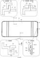
- 2 is a front view of the radar cover 60 attached to the bracket 50.
- FIG. 2 is an exploded perspective view of the bracket 50 and the radar cover 60.
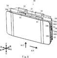
- FIG. 13 is a perspective view showing a state in which the rear side of the radar cover 60 abuts against the front side of the bracket 50 and the intermediate engaged portion 63 of the radar cover 60 is disposed below the hook portion 54 of the bracket 50.
- FIG. 13 is a perspective view showing a state in which the rear side of the radar cover 60 abuts against the front side of the bracket 50 and the intermediate engaged portion 63 of the radar cover
- the vehicle lamp 10 of this embodiment is a vehicle lamp that functions as a headlamp and is mounted on both the left and right sides of the front end of a vehicle such as an automobile (not shown). Since the vehicle lamps 10 mounted on both the left and right sides have a symmetrical configuration, the following description will be directed to the vehicle lamp 10 mounted on the left side of the front end of the vehicle (the left side when facing the front of the vehicle) as a representative example.
- FIG. 1 is a perspective view of the vicinity of a vehicle lamp 10 mounted on a vehicle
- FIG. 2 is a view seen from the direction of arrow Ar1 in FIG. 1
- FIG. 3 is a top view (schematic diagram) of the vehicle lamp 10
- FIG. 4 is a cross-sectional view taken along the line IV-IV in FIG. 2
- FIG. 5 is an exploded perspective view of the vehicle lamp 10.
- the vehicle lamp 10 includes a lamp housing 20, an outer lens 30, a lamp unit 40, a bracket 50, a radar cover 60, and a radar unit 70.
- the reference numeral 100 in Figure 3 denotes the vehicle body.
- the outer lens 30 is attached to the lamp housing 20 to form a lamp chamber S1 (see FIG. 4, etc.) between the outer lens 30 and the lamp housing 20.
- a lamp unit 40 is disposed within the lamp chamber S1.
- the lamp unit 40 may have any configuration as long as it is a lamp unit that emits light that functions as a headlamp.
- the lamp unit 40 may be a projector type lamp unit, a reflector type lamp unit, a direct projection type lamp unit, a lamp unit that uses a light guide (light guide rod, light guide plate), or a lamp unit other than these.
- the outer lens 30 is made of a transparent resin (synthetic resin) such as acrylic or polycarbonate, and includes a lens portion 31 through which the light emitted by the lamp unit 40 passes, and a recessed portion 32 that is recessed from the front side toward the rear side (the lamp housing 20 side).
- the lens portion 31 is positioned on the inside in the vehicle width direction, and the recessed portion 32 is positioned on the outside in the vehicle width direction.
- the recess 32 is composed of an opening end 32a on the front side, a bottom 32b on the rear side, and inner walls 32c (upper inner wall 32c1, lower inner wall 32c2, inner inner wall 32c3, outer inner wall 32c4) between the opening end 32a and the bottom 32b.
- the bracket 50 is removably attached to the outer lens 30 (recess 32) configured as described above.
- Figure 6 is a front view of the radar cover 60 attached to the bracket 50
- Figure 7 is an exploded perspective view of the bracket 50 and the radar cover 60.
- the bracket 50 is made of a synthetic resin such as acrylic or polycarbonate, and includes a bracket body 51, an upper engagement portion 52, a lower engagement portion 53, and an intermediate engagement portion 54, as shown in Figures 6 and 7.
- the bracket body 51 includes a radar unit mounting surface 51a and a rear surface 51b on the opposite side (see FIG. 4).
- the radar unit mounting surface 51a is provided with screw bosses 51a1 (three locations) to which the radar unit 70 is screwed (see FIG. 5).
- the upper engaging portion 52 (an example of the second engaging portion of the present disclosure) is a portion that engages with the upper engaged portion 61 of the radar cover 60. As shown in FIG. 7, the upper engaging portion 52 is provided on the tip side (upper end side in FIG. 7) of the bracket 50 (bracket main body 51) in the sliding direction (see arrow Ar2 in FIG. 7) in correspondence with the upper engaged portion 61 of the radar cover 60. Specifically, as shown in the B-B cross-sectional view in FIG. 6, the upper engaging portion 52 includes a first extension portion 52a that extends forward from the tip side (upper end side in FIG.
- bracket 50 (bracket main body 51) in the sliding direction
- second extension portion 52b that extends downward from the tip of the first extension portion 52a.
- a space S2 into which the upper engaged portion 61 of the radar cover 60 is inserted is formed between the bracket 50 (bracket main body 51) and the second extension portion 52b (see B-B cross-sectional view in FIG. 6).
- the upper engagement portion 52 may include a first extension portion 52c extending upward from the tip side (upper end side in FIG. 6) of the bracket 50 (bracket body 51) in the sliding direction, and a second extension portion 52d extending forward from the tip end of the first extension portion 52c.
- a through hole 52d1 is formed in the second extension portion 52d, into which the upper engagement portion 61 of the radar cover 60 is inserted (see the B-B cross section (modified example) in FIG. 6).
- the lower engaging portion 53 (an example of a third engaging portion of the present disclosure) is a portion that engages with the lower engaged portion 62 of the radar cover 60. As shown in FIG. 7, the lower engaging portion 53 is provided on the base end side (lower end side in FIG. 7) of the bracket 50 in the sliding direction (see arrow Ar2 in FIG. 7) in correspondence with the lower engaged portion 62 of the radar cover 60. Specifically, as shown in the CC cross-sectional view in FIG. 6, the lower engaging portion 53 is an extension that extends downward from the base end side (lower end side in FIG. 6) of the bracket 50 (bracket main body 51) in the sliding direction.
- the intermediate engaging portion 54 (an example of a first engaging portion in the present disclosure) is a hook portion that engages with the intermediate engaged portion 63 of the radar cover 60.
- the hook portion 54 As shown in FIG. 7, the hook portions 54 are provided on both sides and above and below the front side of the bracket 50 (bracket body 51) in the sliding direction (see arrow Ar2 in FIG. 7) in correspondence with the intermediate engaged portion 63 of the radar cover 60.
- the hook portions 54 include a fixed portion 54a fixed to the front side of the bracket 50 (bracket body 51) and an extension portion 54b extending downward from the fixed portion 54a.
- a recess 54b1 that engages with the intermediate engaged portion 63 (convex portion) of the radar cover 60 is formed at the tip of the extension portion 54b.
- the bracket 50 configured as described above is detachably attached to the outer lens 30 (recess 32). Specifically, the bracket 50 is attached to the outer lens 30 or the lamp housing 20 by known fixing means (screws, hooks, etc.) with its back surface facing the bottom 32b of the recess 32 (see Figure 4).
- the radar cover 60 includes an upper engaged portion 61, a lower engaged portion 62, and an intermediate engaged portion 63.
- the upper engaged portion 61 (an example of a second engaged portion in the present disclosure) is a portion that engages with the upper engaging portion 52 of the bracket 50. As shown in FIG. 7, the upper engaged portion 61 is provided on the tip side (upper end side in FIG. 7) of the radar cover 60 in the sliding direction (see arrow Ar2 in FIG. 7) in correspondence with the upper engaging portion 52 of the bracket 50. Specifically, as shown in the B-B cross-sectional view in FIG. 6, the upper engaged portion 61 is an extension that extends upward from the tip side (upper end side in FIG. 6) of the radar cover 60 in the sliding direction.
- the lower engaged portion 62 (an example of a third engaged portion in the present disclosure) is a portion that engages with the lower engaging portion 53 of the bracket 50.
- the lower engaged portion 62 is provided on the base end side (lower end side in FIG. 7) of the radar cover 60 in the sliding direction (see arrow Ar2 in FIG. 7) in correspondence with the lower engaging portion 53 of the bracket 50.
- the lower engaged portion 62 includes a first extension portion 62a extending rearward from the base end side (lower end side in FIG. 6) of the radar cover 60 in the sliding direction, and a second extension portion 62b extending upward from the tip of the first extension portion 62a.
- a space S3 into which the lower engaging portion 53 of the bracket 50 is inserted is formed between the radar cover 60 and the second extension portion 62b (see CC cross-sectional view in FIG. 6).
- the intermediate engaged portion 63 (an example of a first engaged portion in this disclosure) is a portion with which the hook portion 54 (intermediate engaged portion) of the bracket 50 engages. As shown in FIG. 7, the intermediate engaged portions 63 are provided on both sides of the radar cover 60 in the sliding direction (see arrow Ar2 in FIG. 7) and on the top and bottom to correspond to the hook portion 54 of the bracket 50. Specifically, the intermediate engaged portions 63 are convex portions with which the hook portion 54 (concave portion 54b1) of the bracket 50 engages (see the D-D cross-sectional view in FIG. 6).
- the radar cover 60 configured as described above is detachably attached to the bracket 50. Specifically, first, as shown in FIG. 8, the rear side of the radar cover 60 abuts against the front side of the bracket 50 (abutment surface 51a2; see FIG. 7) and the intermediate engaged portion 63 of the radar cover 60 is disposed below the hook portion 54 of the bracket 50, and the radar cover 60 is disposed between the hook portions 54 of the bracket 50 on both the left and right sides.
- FIG. 8 is a perspective view of the state in which the rear side of the radar cover 60 abuts against the front side of the bracket 50 and the intermediate engaged portion 63 of the radar cover 60 is disposed below the hook portion 54 of the bracket 50.
- the radar cover 60 positioned as described above is slid relative to the bracket 50 in the direction of the arrow Ar2 in FIG. 8, so that the upper engaging portion 52 of the bracket 50 engages with the upper engaged portion 61 of the radar cover 60 (see the B-B cross-sectional view in FIG. 6), the lower engaging portion 53 of the bracket 50 engages with the lower engaged portion 62 of the radar cover 60 (see the C-C cross-sectional view in FIG. 6), and the hook portion 54 of the bracket 50 engages with the intermediate engaged portion 63 (convex portion) of the radar cover 60 (see the D-D cross-sectional view in FIG. 6).
- the upper engaged portion 61 (extension portion) of the radar cover 60 is inserted into the upper engaged portion 52 of the bracket 50 (space S2 between the bracket 50 (bracket main body 51) and the second extended portion 52b), as shown in the B-B cross-sectional view in Figure 6.
- the lower engaged portion 53 (extension portion) of the bracket 50 is inserted into the lower engaged portion 62 of the radar cover 60 (space S3 between the radar cover 60 and the second extended portion 62b), as shown in the C-C cross-sectional view in Figure 6.
- the radar cover 60 is guided by the hook portions 54 of the bracket 50 on both the left and right sides and the front side of the bracket 50 (contact surface 51a2), and slides along the hook portions 54 of the bracket 50 on both the left and right sides and the front side of the bracket 50 (contact surface 51a2) in the direction of the arrow Ar2 in FIG. 8 relative to the bracket 50.
- the engaging portions 52 to 54 of the bracket 50 engage with the engaged portions 61 to 63 of the radar cover 60, so that the radar cover 60 is detachably attached to the bracket 50 in a state where it is positioned relative to the bracket 50 in the up-down, front-rear, and left-right directions.
- the front side (left side in FIG. 4) end E 32c1 of the upper inner wall 32c1 constituting the recess 32 extends to the radar cover 60
- the front side (left side in FIG. 4) end E 32c2 of the lower inner wall 32c2 constituting the recess 32 extends to the bracket 50 (see FIG. 4). Therefore, the lower end of the radar cover 60 is exposed from the recess 32 without being covered by the lower inner wall 32c2. This allows the radar cover 60 to be attached to and detached from the bracket 50 attached to the outer lens 30 without removing the bracket 50 from the outer lens 30.
- the radar unit 70 (radar device) has a case 71, a transmitting antenna, a receiving antenna (neither of which is shown) housed in the case 71, and the like.
- the radar unit 70 is a millimeter wave radar unit that transmits electromagnetic waves (millimeter waves) from the transmitting antenna.
- the electromagnetic waves (millimeter waves) are transmitted through the radar cover 60 to a range of a vertical spread angle ⁇ V (see FIG. 4) and a horizontal spread angle ⁇ H (see FIG. 3).
- the radar unit 70 receives the reflected waves that are reflected by an object present within the transmission range and transmitted through the radar cover 60 by the receiving antenna.
- the received signal is processed by a control device, for example, an ECU (Electronic Control Unit) (not shown), and the object (distance, angle, and speed between the object and the radar unit) is detected.
- a control device for example, an ECU (Electronic Control Unit) (not shown), and the object (distance, angle, and speed between the object and the radar unit) is detected.
- the radar unit 70 for example, millimeter waves in the 76-81 GHz band, particularly millimeter waves in the 79 GHz band, are used, but are not limited to this frequency band.
- the radar system of the radar unit 70 may be a pulse system, a CW (Continuous Wave) system, or another system.
- the antenna system of the radar unit 70 may be a mechanical scanning system, a beam switching system, a phased array system, a digital forming system, or another system.
- the radar unit 70 configured as described above is detachably attached to the bracket 50 (bracket body 51). Specifically, as shown in FIG. 7, the radar unit 70 is attached to the bracket 50 (bracket body 51) by screwing the screws N1 inserted into the flange portion 72 (three places) of the radar unit 70 into the screw bosses 51a1 of the radar unit mounting surface 51a of the bracket 50 with its back surface facing the radar unit mounting surface 51a of the bracket 50.
- the bracket 50 is attached to the outer lens 30 (recess 32). Specifically, the bracket 50 is detachably attached to the outer lens 30 (recess 32) with its back surface facing the bottom 32b of the recess 32 using known fastening means (screws, hooks, etc.).
- the vehicle lamp 10 with the bracket 50 attached as described above is attached to the vehicle body using known fixing means (screws, etc.).
- the radar unit 70 is attached to the bracket 50.
- the radar unit 70 is detachably attached to the bracket 50 (bracket body 51) by screwing the screws N1 inserted into the flange portion 72 (three places) of the radar unit 70 into the screw bosses 51a1 of the radar unit mounting surface 51a of the bracket 50 with its back surface facing the radar unit mounting surface 51a of the bracket 50.
- the radar cover 60 is attached to the bracket 50. Specifically, first, as shown in FIG. 8, the rear side of the radar cover 60 is abutted against the front side of the bracket 50 (abutment surface 51a2; see FIG. 7), and the intermediate engaged portion 63 of the radar cover 60 is positioned below the hook portion 54 of the bracket 50, and the radar cover 60 is placed between the hook portions 54 of the bracket 50 on both the left and right sides.
- the radar cover 60 positioned as described above is slid relative to the bracket 50 in the direction of the arrow Ar2 in FIG. 8, so that the upper engaging portion 52 of the bracket 50 engages with the upper engaged portion 61 of the radar cover 60 (see the B-B cross-sectional view in FIG. 6), the lower engaging portion 53 of the bracket 50 engages with the lower engaged portion 62 of the radar cover 60 (see the C-C cross-sectional view in FIG. 6), and the hook portion 54 of the bracket 50 engages with the intermediate engaged portion 63 (convex portion) of the radar cover 60 (see the D-D cross-sectional view in FIG. 6).
- the radar cover 60 is guided by the hook portions 54 of the bracket 50 on both the left and right sides and the front side of the bracket 50 (contact surface 51a2), and slides relative to the bracket 50 along the hook portions 54 of the bracket 50 on both the left and right sides and the front side of the bracket 50 (contact surface 51a2) in the direction of the arrow Ar2 in FIG. 8.
- the engaging portions 52-54 of the bracket 50 engage with the engaged portions 61-63 of the radar cover 60, so that the radar cover 60 is removably attached to the bracket 50 while being positioned relative to the bracket 50 in the up-down, front-back, and left-right directions.
- the bumper 90 is attached to the vehicle body. Specifically, as shown in Figures 1 and 4, the bumper 90 is detachably attached to the vehicle body by known fastening means (screws, etc.) while covering the lower end of the radar cover 60 below.
- the vehicle lamp 10 is attached to the vehicle body.
- This procedure is performed, for example, when replacing the radar unit 70 in the event of a malfunction of the radar unit 70, or when rewriting the control program stored in a memory unit such as a ROM built into the radar unit 70 (for example, when upgrading).
- the radar cover 60 is slid relative to the bracket 50 in the direction of the arrow Ar3 in FIG. 4 to release the engagement of the upper engagement portion 52 of the bracket 50 with the upper engaged portion 61 of the radar cover 60 (see the B-B cross section in FIG. 6), the engagement of the lower engagement portion 53 of the bracket 50 with the lower engaged portion 62 of the radar cover 60 (see the C-C cross section in FIG. 6), and the engagement of the hook portion 54 of the bracket 50 with the intermediate engaged portion 63 (convex portion) of the radar cover 60 (see the D-D cross section in FIG. 6).
- the radar cover 60 is guided by the hook portions 54 of the bracket 50 on both the left and right sides and slides relative to the bracket 50 in the direction of the arrow Ar3 in FIG. 4 along the hook portions 54 of the bracket 50 on both the left and right sides.
- the radar cover 60 can be removed from the bracket 50.
- the radar unit 70 can be removed from the bracket 50.
- the radar cover 60 it is possible to provide a radar cover attachment/detachment structure that allows the radar cover 60 to be detachably attached to the bracket 50 by sliding the radar cover 60 in one direction (see arrow Ar2 in FIG. 8) relative to the bracket 50. Furthermore, according to this embodiment, the radar cover 60 can be attached and detached without using tools. Furthermore, according to this embodiment, since no tools are used when attaching and detaching the radar cover 60, it is possible to prevent the tools from coming into contact with the surroundings (e.g., the outer lens 30, the bumper 90) and causing damage. Furthermore, according to this embodiment, it is possible to reduce variation between workers when attaching and detaching the radar cover 60.
- the upper engaging portion 52, the lower engaging portion 53, and the intermediate engaging portion 54 are provided on the bracket 50, and the upper engaged portion 61, the lower engaged portion 62, and the intermediate engaged portion 63 are provided on the radar cover 60, but this is not limited to the above.
- the upper engaging portion 52, the lower engaging portion 53, and the intermediate engaging portion 54 may be provided on the radar cover 60, and the upper engaged portion 61, the lower engaged portion 62, and the intermediate engaged portion 63 may be provided on the bracket 50.
- the radar cover 60 is slid relative to the bracket 50 in the direction of the arrow Ar2 in FIG. 8, but this is not limiting.
- the radar cover 60 may be slid relative to the bracket 50 in another direction, such as the direction of the arrow Ar4 in FIG. 8.
- a bumper 90 was used as the vehicle-side member, but this is not limited to this.
- Various members other than a bumper may be used as the vehicle-side member.
Landscapes
- Engineering & Computer Science (AREA)
- Computer Networks & Wireless Communication (AREA)
- Physics & Mathematics (AREA)
- General Physics & Mathematics (AREA)
- Radar, Positioning & Navigation (AREA)
- Remote Sensing (AREA)
- Radar Systems Or Details Thereof (AREA)
Priority Applications (1)
| Application Number | Priority Date | Filing Date | Title |
|---|---|---|---|
| CN202480033160.8A CN121127763A (zh) | 2023-05-18 | 2024-05-10 | 雷达罩附接/拆卸结构 |
Applications Claiming Priority (2)
| Application Number | Priority Date | Filing Date | Title |
|---|---|---|---|
| JP2023-082295 | 2023-05-18 | ||
| JP2023082295A JP2024165800A (ja) | 2023-05-18 | 2023-05-18 | レーダカバー着脱構造 |
Publications (1)
| Publication Number | Publication Date |
|---|---|
| WO2024237176A1 true WO2024237176A1 (ja) | 2024-11-21 |
Family
ID=93519636
Family Applications (1)
| Application Number | Title | Priority Date | Filing Date |
|---|---|---|---|
| PCT/JP2024/017337 Ceased WO2024237176A1 (ja) | 2023-05-18 | 2024-05-10 | レーダカバー着脱構造 |
Country Status (3)
| Country | Link |
|---|---|
| JP (1) | JP2024165800A (https=) |
| CN (1) | CN121127763A (https=) |
| WO (1) | WO2024237176A1 (https=) |
Citations (7)
| Publication number | Priority date | Publication date | Assignee | Title |
|---|---|---|---|---|
| JP2005291789A (ja) * | 2004-03-31 | 2005-10-20 | Denso Corp | 距離検出装置 |
| JP2016121927A (ja) * | 2014-12-25 | 2016-07-07 | 本田技研工業株式会社 | 物体検知装置 |
| JP2019184335A (ja) * | 2018-04-05 | 2019-10-24 | 株式会社デンソーテン | レーダ装置 |
| JP2021025849A (ja) * | 2019-08-02 | 2021-02-22 | 日産自動車株式会社 | レーダモジュールの車載構造 |
| US20210123778A1 (en) * | 2019-10-25 | 2021-04-29 | Hyundai Mobis Co., Ltd. | Sensor-cluster apparatus |
| WO2023079963A1 (ja) * | 2021-11-05 | 2023-05-11 | 株式会社小糸製作所 | 車両用灯具 |
| JP2023068630A (ja) * | 2021-11-02 | 2023-05-17 | スタンレー電気株式会社 | 車両用灯具及びレーダ構造体 |
-
2023
- 2023-05-18 JP JP2023082295A patent/JP2024165800A/ja active Pending
-
2024
- 2024-05-10 CN CN202480033160.8A patent/CN121127763A/zh active Pending
- 2024-05-10 WO PCT/JP2024/017337 patent/WO2024237176A1/ja not_active Ceased
Patent Citations (7)
| Publication number | Priority date | Publication date | Assignee | Title |
|---|---|---|---|---|
| JP2005291789A (ja) * | 2004-03-31 | 2005-10-20 | Denso Corp | 距離検出装置 |
| JP2016121927A (ja) * | 2014-12-25 | 2016-07-07 | 本田技研工業株式会社 | 物体検知装置 |
| JP2019184335A (ja) * | 2018-04-05 | 2019-10-24 | 株式会社デンソーテン | レーダ装置 |
| JP2021025849A (ja) * | 2019-08-02 | 2021-02-22 | 日産自動車株式会社 | レーダモジュールの車載構造 |
| US20210123778A1 (en) * | 2019-10-25 | 2021-04-29 | Hyundai Mobis Co., Ltd. | Sensor-cluster apparatus |
| JP2023068630A (ja) * | 2021-11-02 | 2023-05-17 | スタンレー電気株式会社 | 車両用灯具及びレーダ構造体 |
| WO2023079963A1 (ja) * | 2021-11-05 | 2023-05-11 | 株式会社小糸製作所 | 車両用灯具 |
Also Published As
| Publication number | Publication date |
|---|---|
| CN121127763A (zh) | 2025-12-12 |
| JP2024165800A (ja) | 2024-11-28 |
Similar Documents
| Publication | Publication Date | Title |
|---|---|---|
| JP7416803B2 (ja) | 車両用灯具及び車両 | |
| US11634064B1 (en) | Vehicular lamp fitting and radar structure | |
| JP7132887B2 (ja) | 車両用灯体 | |
| JP7124147B1 (ja) | レーダ搭載構造 | |
| EP4174513B1 (en) | Vehicular lamp fitting and radar structure | |
| US12325350B2 (en) | Vehicular lamp | |
| JP7099991B2 (ja) | 車両用灯体 | |
| WO2024237179A1 (ja) | レーダカバー着脱構造 | |
| WO2024237176A1 (ja) | レーダカバー着脱構造 | |
| US20200132813A1 (en) | Vehicle front structure | |
| US12559021B2 (en) | Vehicular lamp fitting | |
| US11693095B2 (en) | Sensor mounting structure | |
| US20230139713A1 (en) | Vehicular lamp fitting and radar structure | |
| JP7138597B2 (ja) | 車両用灯体 | |
| US12263778B2 (en) | Bracket attachment structure | |
| CN113508057B (zh) | 车辆前部构造 | |
| US12434619B2 (en) | Bracket attachment structure | |
| JP2023092740A (ja) | 車体構造 |
Legal Events
| Date | Code | Title | Description |
|---|---|---|---|
| 121 | Ep: the epo has been informed by wipo that ep was designated in this application |
Ref document number: 24807128 Country of ref document: EP Kind code of ref document: A1 |
|
| NENP | Non-entry into the national phase |
Ref country code: DE |