WO2024237148A1 - 成形システム、成形装置、及び成形方法 - Google Patents
成形システム、成形装置、及び成形方法 Download PDFInfo
- Publication number
- WO2024237148A1 WO2024237148A1 PCT/JP2024/017153 JP2024017153W WO2024237148A1 WO 2024237148 A1 WO2024237148 A1 WO 2024237148A1 JP 2024017153 W JP2024017153 W JP 2024017153W WO 2024237148 A1 WO2024237148 A1 WO 2024237148A1
- Authority
- WO
- WIPO (PCT)
- Prior art keywords
- forming
- molding
- metal pipe
- treatment
- aging treatment
- Prior art date
- Legal status (The legal status is an assumption and is not a legal conclusion. Google has not performed a legal analysis and makes no representation as to the accuracy of the status listed.)
- Ceased
Links
Images


Classifications
-
- B—PERFORMING OPERATIONS; TRANSPORTING
- B21—MECHANICAL METAL-WORKING WITHOUT ESSENTIALLY REMOVING MATERIAL; PUNCHING METAL
- B21D—WORKING OR PROCESSING OF SHEET METAL OR METAL TUBES, RODS OR PROFILES WITHOUT ESSENTIALLY REMOVING MATERIAL; PUNCHING METAL
- B21D26/00—Shaping without cutting otherwise than using rigid devices or tools or yieldable or resilient pads, i.e. applying fluid pressure or magnetic forces
- B21D26/02—Shaping without cutting otherwise than using rigid devices or tools or yieldable or resilient pads, i.e. applying fluid pressure or magnetic forces by applying fluid pressure
- B21D26/033—Deforming tubular bodies
- B21D26/035—Deforming tubular bodies including an additional treatment performed by fluid pressure, e.g. perforating
-
- B—PERFORMING OPERATIONS; TRANSPORTING
- B21—MECHANICAL METAL-WORKING WITHOUT ESSENTIALLY REMOVING MATERIAL; PUNCHING METAL
- B21D—WORKING OR PROCESSING OF SHEET METAL OR METAL TUBES, RODS OR PROFILES WITHOUT ESSENTIALLY REMOVING MATERIAL; PUNCHING METAL
- B21D22/00—Shaping without cutting, by stamping, spinning, or deep-drawing
- B21D22/20—Deep-drawing
- B21D22/208—Deep-drawing by heating the blank or deep-drawing associated with heat treatment
-
- B—PERFORMING OPERATIONS; TRANSPORTING
- B21—MECHANICAL METAL-WORKING WITHOUT ESSENTIALLY REMOVING MATERIAL; PUNCHING METAL
- B21D—WORKING OR PROCESSING OF SHEET METAL OR METAL TUBES, RODS OR PROFILES WITHOUT ESSENTIALLY REMOVING MATERIAL; PUNCHING METAL
- B21D24/00—Special deep-drawing arrangements in, or in connection with, presses
-
- B—PERFORMING OPERATIONS; TRANSPORTING
- B21—MECHANICAL METAL-WORKING WITHOUT ESSENTIALLY REMOVING MATERIAL; PUNCHING METAL
- B21D—WORKING OR PROCESSING OF SHEET METAL OR METAL TUBES, RODS OR PROFILES WITHOUT ESSENTIALLY REMOVING MATERIAL; PUNCHING METAL
- B21D26/00—Shaping without cutting otherwise than using rigid devices or tools or yieldable or resilient pads, i.e. applying fluid pressure or magnetic forces
- B21D26/02—Shaping without cutting otherwise than using rigid devices or tools or yieldable or resilient pads, i.e. applying fluid pressure or magnetic forces by applying fluid pressure
- B21D26/033—Deforming tubular bodies
-
- B—PERFORMING OPERATIONS; TRANSPORTING
- B21—MECHANICAL METAL-WORKING WITHOUT ESSENTIALLY REMOVING MATERIAL; PUNCHING METAL
- B21D—WORKING OR PROCESSING OF SHEET METAL OR METAL TUBES, RODS OR PROFILES WITHOUT ESSENTIALLY REMOVING MATERIAL; PUNCHING METAL
- B21D26/00—Shaping without cutting otherwise than using rigid devices or tools or yieldable or resilient pads, i.e. applying fluid pressure or magnetic forces
- B21D26/02—Shaping without cutting otherwise than using rigid devices or tools or yieldable or resilient pads, i.e. applying fluid pressure or magnetic forces by applying fluid pressure
- B21D26/033—Deforming tubular bodies
- B21D26/041—Means for controlling fluid parameters, e.g. pressure or temperature
-
- B—PERFORMING OPERATIONS; TRANSPORTING
- B21—MECHANICAL METAL-WORKING WITHOUT ESSENTIALLY REMOVING MATERIAL; PUNCHING METAL
- B21D—WORKING OR PROCESSING OF SHEET METAL OR METAL TUBES, RODS OR PROFILES WITHOUT ESSENTIALLY REMOVING MATERIAL; PUNCHING METAL
- B21D26/00—Shaping without cutting otherwise than using rigid devices or tools or yieldable or resilient pads, i.e. applying fluid pressure or magnetic forces
- B21D26/02—Shaping without cutting otherwise than using rigid devices or tools or yieldable or resilient pads, i.e. applying fluid pressure or magnetic forces by applying fluid pressure
- B21D26/053—Shaping without cutting otherwise than using rigid devices or tools or yieldable or resilient pads, i.e. applying fluid pressure or magnetic forces by applying fluid pressure characterised by the material of the blanks
-
- C—CHEMISTRY; METALLURGY
- C21—METALLURGY OF IRON
- C21D—MODIFYING THE PHYSICAL STRUCTURE OF FERROUS METALS; GENERAL DEVICES FOR HEAT TREATMENT OF FERROUS OR NON-FERROUS METALS OR ALLOYS; MAKING METAL MALLEABLE, e.g. BY DECARBURISATION OR TEMPERING
- C21D1/00—General methods or devices for heat treatment, e.g. annealing, hardening, quenching or tempering
- C21D1/62—Quenching devices
-
- C—CHEMISTRY; METALLURGY
- C21—METALLURGY OF IRON
- C21D—MODIFYING THE PHYSICAL STRUCTURE OF FERROUS METALS; GENERAL DEVICES FOR HEAT TREATMENT OF FERROUS OR NON-FERROUS METALS OR ALLOYS; MAKING METAL MALLEABLE, e.g. BY DECARBURISATION OR TEMPERING
- C21D1/00—General methods or devices for heat treatment, e.g. annealing, hardening, quenching or tempering
- C21D1/62—Quenching devices
- C21D1/673—Quenching devices for die quenching
-
- C—CHEMISTRY; METALLURGY
- C21—METALLURGY OF IRON
- C21D—MODIFYING THE PHYSICAL STRUCTURE OF FERROUS METALS; GENERAL DEVICES FOR HEAT TREATMENT OF FERROUS OR NON-FERROUS METALS OR ALLOYS; MAKING METAL MALLEABLE, e.g. BY DECARBURISATION OR TEMPERING
- C21D9/00—Heat treatment, e.g. annealing, hardening, quenching or tempering, adapted for particular articles; Furnaces therefor
- C21D9/0062—Heat-treating apparatus with a cooling or quenching zone
-
- C—CHEMISTRY; METALLURGY
- C21—METALLURGY OF IRON
- C21D—MODIFYING THE PHYSICAL STRUCTURE OF FERROUS METALS; GENERAL DEVICES FOR HEAT TREATMENT OF FERROUS OR NON-FERROUS METALS OR ALLOYS; MAKING METAL MALLEABLE, e.g. BY DECARBURISATION OR TEMPERING
- C21D9/00—Heat treatment, e.g. annealing, hardening, quenching or tempering, adapted for particular articles; Furnaces therefor
- C21D9/08—Heat treatment, e.g. annealing, hardening, quenching or tempering, adapted for particular articles; Furnaces therefor for tubular bodies or pipes
- C21D9/085—Cooling or quenching
-
- C—CHEMISTRY; METALLURGY
- C22—METALLURGY; FERROUS OR NON-FERROUS ALLOYS; TREATMENT OF ALLOYS OR NON-FERROUS METALS
- C22F—CHANGING THE PHYSICAL STRUCTURE OF NON-FERROUS METALS AND NON-FERROUS ALLOYS
- C22F1/00—Changing the physical structure of non-ferrous metals or alloys by heat treatment or by hot or cold working
- C22F1/002—Changing the physical structure of non-ferrous metals or alloys by heat treatment or by hot or cold working by rapid cooling or quenching; cooling agents used therefor
-
- C—CHEMISTRY; METALLURGY
- C22—METALLURGY; FERROUS OR NON-FERROUS ALLOYS; TREATMENT OF ALLOYS OR NON-FERROUS METALS
- C22F—CHANGING THE PHYSICAL STRUCTURE OF NON-FERROUS METALS AND NON-FERROUS ALLOYS
- C22F1/00—Changing the physical structure of non-ferrous metals or alloys by heat treatment or by hot or cold working
- C22F1/04—Changing the physical structure of non-ferrous metals or alloys by heat treatment or by hot or cold working of aluminium or alloys based thereon
Definitions
- This disclosure relates to a molding system, a molding device, and a molding method.
- Patent Document 1 A conventional molding device for forming metal materials is described in Patent Document 1. This molding device forms parts of a desired shape by pressing the metal material.
- Parts formed by the above-mentioned forming apparatus are used to construct specified structures. For example, weight reduction is being promoted in the field of automobiles to improve fuel efficiency and protect the environment. For this reason, materials that undergo solution, such as heat-treatable aluminum alloys, are used, and the formed products are quenched by heating, expansion forming, and then rapidly cooling by removing heat through contact with a mold.
- materials that undergo solution such as heat-treatable aluminum alloys
- the present disclosure therefore aims to provide a molding system, molding device, and molding method that can improve the strength of molded products while ensuring the dimensional accuracy of the molded products.
- the forming device forms the heated metal material to perform quenching.
- the aging treatment device then performs aging treatment on the formed product formed by the forming device.
- the forming device forms the metal material after solution treatment and artificial aging treatment. Therefore, even when rapid heating is performed in the forming device with a small amount of heat input, the precipitates of the metal material are in a solid solution state. Therefore, in the subsequent aging treatment device, the precipitates can be made to be finely dispersed in the formed product (see, for example, Figure 8). This can improve the strength of the formed product.
- the dimensional accuracy of the formed product can also be prevented from decreasing. As a result, the strength of the formed product can be improved while maintaining the dimensional accuracy of the formed product.
- the forming device may be used to form metal materials after T6 treatment. In this case, the strength of the formed product after aging treatment can be improved.
- the metal material may be an aluminum alloy.
- Aluminum alloys have a low specific gravity and can reduce the weight of molded products.
- the forming device may form a metal material heated to 400°C or higher. This allows the precipitates to form into a solid solution.
- the forming device is a forming device that performs quenching by forming a heated metal material, and forms a formed product in which the solid solution state of the precipitates is maintained at the stage after forming and before aging treatment is performed.
- This forming device can form a molded product in which the precipitates maintain their solid solution state after forming and before aging treatment is performed. Therefore, in the subsequent aging treatment device, the precipitates can be made to be finely dispersed within the molded product (see Figure 8, for example). This can improve the strength of the molded product. In addition, since there is no need to perform solution treatment or the like to improve strength after forming in the forming device, a decrease in the dimensional accuracy of the molded product can also be suppressed. As a result, the strength of the molded product can be improved while maintaining the dimensional accuracy of the product.
- the forming method according to one embodiment of the present disclosure is a forming method for forming a metal material, in which the metal material is heated after solution treatment and artificial aging treatment, formed, and quenched.
- This molding method can achieve the same effects and benefits as the molding system described above.
- This disclosure provides a molding system, molding device, and molding method that can improve the strength of molded products while ensuring their dimensional accuracy.
- FIG. 1 is a block diagram showing a molding system according to an embodiment of the present disclosure.
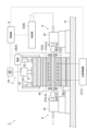
- FIG. 1 is a schematic configuration diagram showing a molding device according to an embodiment of the present disclosure.
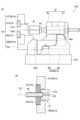
- Fig. 2(a) is a schematic side view showing the thermal expansion unit
- Fig. 2(b) is a cross-sectional view showing the state when the nozzle seals the metal pipe material.
- FIG. 1 is a schematic diagram showing a process image in Comparative Example 1.
- FIG. 13 is a diagram showing the relationship between material temperature and strength and time in Comparative Examples 1 and 2.
- FIG. 13 is a diagram showing the relationship between material temperature and strength and time in Comparative Example 3.
- FIG. 13 is a diagram showing the relationship between material temperature and strength and time in Comparative Example 4.
- FIG. 1 is a block diagram showing a molding system according to an embodiment of the present disclosure.
- FIG. 1 is a schematic configuration diagram showing a molding device according to an embodiment of the present disclosure.
- Fig. 2(a) is a schematic
- FIG. 1 is a diagram showing the relationship between material temperature and strength and time in an embodiment.
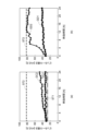
- 1 is a graph showing the relationship between Vickers hardness and aging time in Comparative Example 2 and the Examples.
- 1 is a graph showing the relationship between heating temperature and hardness when T6 treated material is subjected to rapid heating and water cooling, and then artificial aging and natural aging.
- 1 is a graph showing an image of the relationship between thermal aging time, strength, precipitate size, and precipitate density of a precipitation hardened aluminum alloy.
- FIG. 1 is an image diagram showing the process of change in precipitate size and precipitate density in the material during the manufacturing process of Comparative Example 1 and Comparative Example 2.
- FIG. 1 is a block diagram of a molding system 100 according to this embodiment.
- the molding system 100 is a system for molding a metal material.
- an aluminum alloy metal pipe material is used as the metal material. This results in a metal pipe being molded as a molded product.
- the metal material is not limited to an aluminum alloy as long as it can be subjected to solution treatment, and a nickel alloy or the like may also be used.
- the forming system 100 includes a forming device 1 and an aging treatment device 101.
- the forming device 1 is a device that performs quenching by expanding and forming a heated metal material.
- the forming device 1 forms a metal pipe by a forming method called STAF (Steel Tube Air Forming) forming.
- the aging treatment device 101 is a device that performs aging treatment on the metal pipe formed by the forming device 1.
- the aging treatment device 101 is composed of, for example, a furnace that heats the metal pipe for a predetermined period of time immediately after forming.
- the formed metal pipe is removed from the forming device 1 and transported to the aging treatment device 101 by a transport mechanism or the like.
- the aging treatment device 101 performs heating at, for example, 100 to 170°C for 12 to 24 hours.
- FIG. 2 is a schematic diagram of the molding device 1 according to this embodiment.
- the molding device 1 is a device that molds a metal pipe having a hollow shape by blow molding.
- the molding device 1 is installed on a horizontal surface.
- the molding device 1 includes a molding die 2, a drive mechanism 3, a holding unit 4, a heating unit 5, a fluid supply unit 6, a cooling unit 7, and a control unit 8.
- the metal pipe material 40 (metal material) refers to a hollow article before the completion of molding in the molding device 1.
- the metal pipe material 40 is a pipe material of a steel type that can be hardened.
- the direction in which the metal pipe material 40 extends during molding may be referred to as the "longitudinal direction”
- the direction perpendicular to the longitudinal direction may be referred to as the "width direction”.
- the forming die 2 is a die for forming a metal pipe from the metal pipe material 40, and includes a lower die 11 and an upper die 12 that face each other in the vertical direction.
- the lower die 11 and the upper die 12 are made of steel blocks.
- Each of the lower die 11 and the upper die 12 has a recess for accommodating the metal pipe material 40.
- each recess forms a space of the target shape in which the metal pipe material is to be formed. Therefore, the surface of each recess becomes the forming surface of the forming die 2.
- the lower die 11 is fixed to the base 13 via a die holder or the like.
- the upper die 12 is fixed to the slide of the drive mechanism 3 via a die holder or the like.
- the drive mechanism 3 is a mechanism that moves at least one of the lower die 11 and the upper die 12. In FIG. 2, the drive mechanism 3 is configured to move only the upper die 12.
- the drive mechanism 3 includes a slide 21 that moves the upper die 12 so that the lower die 11 and the upper die 12 are aligned, a pullback cylinder 22 as an actuator that generates a force to pull the slide 21 upward, a main cylinder 23 as a drive source that pressurizes the slide 21 downward, and a drive source 24 that applies a drive force to the main cylinder 23.
- the holding unit 4 is a mechanism for holding the metal pipe material 40 disposed between the lower die 11 and the upper die 12.
- the holding unit 4 includes a lower electrode 26 and an upper electrode 27 for holding the metal pipe material 40 at one end in the longitudinal direction of the mold 2, and a lower electrode 26 and an upper electrode 27 for holding the metal pipe material 40 at the other end in the longitudinal direction of the mold 2.
- the lower electrode 26 and the upper electrode 27 on both sides in the longitudinal direction hold the metal pipe material 40 by sandwiching the end of the metal pipe material 40 from above and below.
- a groove having a shape corresponding to the outer peripheral surface of the metal pipe material 40 is formed on the upper surface of the lower electrode 26 and the lower surface of the upper electrode 27.
- the lower electrode 26 and the upper electrode 27 are provided with a driving mechanism (not shown) and can move independently in the vertical direction.
- the heating unit 5 heats the metal pipe material 40.
- the heating unit 5 is a mechanism that heats the metal pipe material 40 by passing electricity through the metal pipe material 40.
- the heating unit 5 heats the metal pipe material 40 between the lower mold 11 and the upper mold 12 while the metal pipe material 40 is separated from the lower mold 11 and the upper mold 12.
- the heating unit 5 includes a lower electrode 26 and an upper electrode 27 on both sides of the longitudinal direction as described above, and a power source 28 that passes current through these electrodes 26, 27 to the metal pipe material 40.
- the heating unit may be disposed in a process preceding the molding device 1 and may be an external heating unit.
- the fluid supply unit 6 is a mechanism for supplying high-pressure fluid into the metal pipe material 40 held between the lower die 11 and the upper die 12.
- the fluid supply unit 6 supplies high-pressure fluid to the metal pipe material 40, which has been heated by the heating unit 5 to a high temperature, to expand the metal pipe material 40.
- the fluid supply unit 6 is provided on both ends of the longitudinal direction of the mold 2.
- the fluid supply unit 6 includes a nozzle 31 that supplies fluid to the inside of the metal pipe material 40 from an opening at the end of the metal pipe material 40, a drive mechanism 32 that moves the nozzle 31 back and forth relative to the opening of the metal pipe material 40, and a supply source 33 that supplies high-pressure fluid into the metal pipe material 40 through the nozzle 31.
- the drive mechanism 32 brings the nozzle 31 into close contact with the end of the metal pipe material 40 while ensuring sealing when supplying and discharging fluid, and moves the nozzle 31 away from the end of the metal pipe material 40 at other times.
- the fluid supply unit 6 may supply a gas such as high-pressure air or an inert gas as the fluid.
- the fluid supply unit 6 may be integrated into the same device as the holding unit 4, which has a mechanism for moving the metal pipe material 40 in the vertical direction, and the heating unit 5.
- FIG. 3(a) is a schematic side view showing the thermal expansion unit 150.
- FIG. 3(b) is a cross-sectional view showing the state when the nozzle 31 seals the metal pipe material 40.
- the thermal expansion unit 150 comprises the above-mentioned lower electrode 26 and upper electrode 27, an electrode mounting unit 151 mounting the electrodes 26, 27, the above-mentioned nozzle 31 and drive mechanism 32, a lifting unit 152, and a unit base 153.
- the electrode mounting unit 151 comprises a lifting frame 154 and electrode frames 156, 157.
- the electrode frames 156, 157 function as part of the drive mechanism 60 that supports and moves the electrodes 26, 27.
- the drive mechanism 32 drives the nozzle 31, and lifts and lowers together with the electrode mounting unit 151.
- the drive mechanism 32 comprises a piston 61 that holds the nozzle 31, and a cylinder 62 that drives the piston.
- the lifting unit 152 includes a lifting frame base 64 attached to the upper surface of the unit base 153, and a lifting actuator 66 that applies lifting and lowering motion to the lifting frame 154 of the electrode mounting unit 151 by means of the lifting frame base 64.
- the lifting frame base 64 has guide parts 64a and 64b that guide the lifting and lowering motion of the lifting frame 154 relative to the unit base 153.
- the lifting unit 152 functions as part of the drive mechanism 60 of the holding part 4.
- the thermal expansion unit 150 has multiple unit bases 153 with different inclination angles of the upper surface, and by replacing these, it is possible to change and adjust the inclination angles of the lower electrode 26, upper electrode 27, nozzle 31, electrode mounting unit 151, drive mechanism 32, and lifting unit 152 all at once.
- the nozzle 31 is a cylindrical member into which the end of the metal pipe material 40 can be inserted.
- the nozzle 31 is supported by the drive mechanism 32 so that the center line of the nozzle 31 coincides with the reference line SL1.
- the inner diameter of the supply port 31a at the end of the nozzle 31 on the metal pipe material 40 side approximately coincides with the outer diameter of the metal pipe material 40 after expansion molding.
- the nozzle 31 supplies high-pressure fluid from the internal flow path 63 to the metal pipe material 40.
- An example of a high-pressure fluid is gas.
- the cooling unit 7 is a mechanism for cooling the forming die 2. By cooling the forming die 2, the cooling unit 7 can rapidly cool the expanded metal pipe material 40 when it comes into contact with the forming surface of the forming die 2.
- the cooling unit 7 includes flow paths 36 formed inside the lower die 11 and the upper die 12, and a water circulation mechanism 37 that supplies cooling water to the flow paths 36 and circulates it.
- the control unit 8 is a device that controls the entire molding device 1.
- the control unit 8 controls the drive mechanism 3, the holding unit 4, the heating unit 5, the fluid supply unit 6, and the cooling unit 7.
- the control unit 8 repeatedly performs the operation of molding the metal pipe material 40 in the molding die 2.
- control unit 8 controls the timing of conveyance from a conveying device such as a robot arm, and places the metal pipe material 40 between the lower die 11 and the upper die 12 in the open state.
- the control unit 8 may have an operator manually place the metal pipe material 40 between the lower die 11 and the upper die 12.
- the control unit 8 also controls the actuators of the holding unit 4 to support the metal pipe material 40 with the lower electrodes 26 on both sides in the longitudinal direction, and then lower the upper electrode 27 to sandwich the metal pipe material 40.
- the control unit 8 also controls the heating unit 5 to electrically heat the metal pipe material 40. As a result, an axial current flows through the metal pipe material 40, and the metal pipe material 40 itself generates heat through Joule heat due to the electrical resistance of the metal pipe material 40 itself.
- the control unit 8 controls the drive mechanism 3 to lower the upper die 12 and bring it close to the lower die 11, and closes the mold 2. Meanwhile, the control unit 8 controls the fluid supply unit 6 to seal the openings at both ends of the metal pipe material 40 with the nozzle 31 and supply fluid. As a result, the metal pipe material 40 softened by heating expands and comes into contact with the molding surface of the mold 2. The metal pipe material 40 is then molded to fit the shape of the molding surface of the mold 2. When a metal pipe with a flange is formed, a part of the metal pipe material 40 is inserted into the gap between the lower die 11 and the upper die 12, and then the mold is closed to crush the inserted part and form a flange part. When the metal pipe material 40 comes into contact with the molding surface, it is quenched by the mold 2 cooled by the cooling unit 7, and the metal pipe material 40 is quenched.
- FIG. 4 is a schematic diagram showing a process image in Comparative Example 1.
- the heating furnace 202 heats the plate material 210 at about 500° C.
- the plate material 210 is a material that has not been previously subjected to solution treatment, such as a cast material or an extruded material.
- the forming device 200 forms the plate material 210 into a formed product 211.
- the formed product 211 is quenched by quenching.
- the treatment by the heating furnace 202 and the forming device 200 corresponds to a solution treatment.
- the aging treatment device 201 performs artificial aging treatment of the formed product 211.
- FIG. 5(a) shows graph GA1, which shows the relationship between material temperature and time, and graph GA2, which shows the relationship between material strength and time, in Comparative Example 1.
- plate material 210 is heated to a temperature equivalent to solution treatment by furnace heating and held at that temperature, and then quenched and formed using a die in forming device 200.
- the desired strength is obtained by performing artificial aging treatment (10 to 24 hours) called T6 treatment in aging treatment device 201.
- T6 treatment in aging treatment device 201.
- “PA1” is the location where the solution treatment temperature is held for several minutes.
- PA2 is the location where hot pressing is performed.
- PA3 is the location where die quenching is performed.
- PA4" is the location where artificial aging treatment is performed.
- Comparative Example 2 an example is shown in which STAF forming (forming using the forming device shown in Figures 2 and 3) is performed using metal pipe material that has not been previously subjected to solution treatment, such as cast material or extruded material.
- Figure 5(b) shows graph GB1, which shows the relationship between material temperature and time, and graph GB2, which shows the relationship between material strength and time, in Comparative Example 2.
- PB1 is the location where electrical heating is performed.
- PB2 is the location where expansion forming is performed.
- PB3 is the location where artificial aging treatment is performed.
- the heating method is electrical heating, so there is no rapid heating or holding step when the heating temperature is reached. Therefore, as shown by "A" in the figure, sufficient solution treatment time is not ensured. Therefore, as shown in graph GB2, the desired strength equivalent to T6 treatment is not obtained even after artificial aging treatment. In contrast, in the STAF forming process, the desired strength can be obtained by performing T6 treatment after electrical heating and forming.
- T6 treatment is a solution treatment of metal pipe material followed by artificial aging treatment.
- T6 treatment is a solution treatment of metal pipe material followed by artificial aging treatment.
- Comparative Example 3 hot stamp processing using a plate material after T6 treatment is illustrated.
- the plate material is heated in a heating furnace.
- the forming device forms the plate material.
- the heating furnace and forming device shown in FIG. 4 may be used.
- FIG. 6 shows a graph GF1 showing the relationship between the material temperature and time, and a graph GF2 showing the relationship between the material strength and time in Comparative Example 3.
- the plate material is heated to 200 to 300°C by furnace heating, and then quenched and formed using a die in the forming device.
- PF1" is the location where heating is performed.
- PF2 is the location where hot pressing is performed.
- PF3 is the location where die quenching is performed.
- Comparative Example 3 there is a problem that the heating temperature is low, so the deformation resistance during forming is high, and there are restrictions on the formed shape.
- Comparative Example 4 hot stamp processing using a solution-treated sheet material is illustrated.
- This sheet material is not subjected to artificial aging treatment after solution treatment.
- the sheet material is heated in a heating furnace.
- the forming device forms the sheet material.
- the desired strength is obtained by performing artificial aging treatment (10 to 24 hours) called T6 treatment in the aging treatment device.
- T6 treatment As the heating furnace, forming device, and aging treatment device, those shown in Figure 4 may be used.
- Figure 7 shows a graph GH1 showing the relationship between the material temperature and time in Comparative Example 4, and a graph GH2 showing the relationship between the material strength and time.
- the sheet material is heated to 350 to 450 ° C.
- PH1 is the part where heating is performed.
- PH2 is the part where hot pressing is performed.
- PH3 is the part where die quenching is performed.
- PH4 is the area where artificial aging treatment has been carried out.
- Comparative Example 4 the material used is after solution treatment, and therefore is in a supersaturated state (i.e., the material is in a thermally unstable state), and depending on the storage conditions (time, temperature, etc.) of the material, natural aging progresses before press forming. This causes a problem of variation in strength after press processing and artificial aging (see GH2x in phantom). Also, in Comparative Example 4, if the heating temperature is set to a high temperature of 500°C or higher, frictional heat between the die and the material during processing causes the material to seize onto the die.
- the forming system 100 forms the metal pipe material 40 after solution treatment and artificial aging treatment in the forming device 1.
- the metal pipe material 40 after T6 treatment is formed.
- electrical heating, forming, and artificial aging treatment using the metal pipe material 40 after T6 treatment it is possible to obtain a molded product of the forming system 100 with strength equivalent to that of T6 treated material.
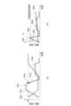
- FIG. 8 shows graph GK1, which shows the relationship between material temperature and time, and graph GK2, which shows the relationship between material strength and time, in the molding system 100 according to the embodiment.
- PK1 in the figure is the location where electrical heating is performed. Here, the heating temperature is raised to 400-610°C. 610°C is a temperature below the melting temperature.
- PK2 is the location where expansion molding is performed.
- PK3 is the location where artificial aging treatment is performed.
- Figure 9(a) shows the aging characteristics when a material that has not been subjected to T6 treatment (as-cast or as-extruded material) is used as the forming material, as in Comparative Example 2.
- Figure 9(b) shows the aging characteristics when A6063 T6-treated material (Example) is used as the forming material, and after rapid heating to a heating temperature of 520°C and water cooling, artificial aging and natural aging are performed.
- Figure 9(a) shows a graph GC1 showing the natural aging characteristics, and a graph GC2 showing the artificial aging characteristics.
- Figure 9(a) also shows a reference line ST1 showing the hardness after annealing (27.0 HV), and a reference line ST2 showing the hardness of the T6-treated material (82.4 HV).
- Figure 9(b) shows a graph GD1 showing the natural aging characteristics, and a graph GD2 showing the artificial aging characteristics.
- FIG. 9(b) also shows a reference line ST2 indicating the hardness of T6 treated material (82.4 HV).
- the material that has not been subjected to T6 treatment shows only a slight increase in hardness even after artificial aging treatment.
- the hardness of the material that has been subjected to T6 treatment increases with the artificial aging time, and after about 12 hours it shows the same hardness as the T6 treated material. In other words, it can be said that the solution treatment is performed even when the material is rapidly heated.
- Figure 10 is a graph showing the relationship between heating temperature and hardness when A6063 T6 treated material is rapidly heated to a heating temperature of 200-520°C, water cooled, and then artificially and naturally aged.
- Graph GL is shown in Figure 10, which shows the relationship between heating temperature and hardness after water cooling.
- a heating temperature of 400°C 16 hours of artificial aging can be achieved to obtain a hardness equivalent to that of T6 treated material, and at a heating temperature of 520°C, 12 hours of artificial aging can be achieved.
- the hardness obtained by artificial aging is harder than the hardness obtained by natural aging for 7 days.
- Figure 11 is a graph showing the relationship between the thermal aging time of a precipitation-hardened aluminum alloy and the strength (graph GE1), precipitate size (graph GE2), and precipitate density (graph GE3).
- the upper part of the graph in Figure 11 shows an image of precipitates in the material as the thermal aging time progresses.
- the atoms that make up the precipitates are completely in solid solution (state 1).
- the thermal aging time progresses
- the atoms that make up the precipitates are in the process of gradually precipitating (state 2).
- state 3 As the thermal aging time progresses further, the atoms that make up the precipitates are completely precipitated (state 3).
- the number density and size of the precipitates also increase.
- Figure 12 is an image diagram showing the process of change in precipitate size and precipitate density in the material during the manufacturing process of Comparative Example 1 and Comparative Example 2.
- Figures 6 to 8 and Figure 12 the state of precipitates in the material during the processing process for each Comparative Example or Example is associated with States 1 to 5 described in Figure 11.
- the precipitates are finely dispersed in the material (T6-treated sheet material) (State 3).
- the size of the precipitates increases during the heating process (State 4), and processing strain is imparted in the subsequent forming process, but the strength is lower than that of the T6-treated material due to the thermal energy imparted during heating.
- the precipitates are in solid solution in the material (solution-treated sheet) (State 1).
- the material is heated to a temperature of 350-450°C, and then immediately cooled in a mold, suppressing the formation of precipitates (State 2).
- artificial aging treatment is performed, making it possible to obtain strength equivalent to T6 treatment (State 3).
- the material used is one that has undergone T6 treatment, so the precipitates are finely dispersed in the material (state 3).
- the precipitates are dissolved by heating to a temperature of 400-610°C in the heating process (state 1). After quenching after forming, the precipitates are not precipitated by quenching, and the solid solution state is maintained (state 1). Finally, the precipitates are finely dispersed by artificial aging (state 3). This makes it possible to obtain strength equivalent to that of T6 treatment.
- the state immediately after molding by the molding device 1 corresponds to the state "State 1" shown as "After molding and rapid cooling". After that, artificial aging is performed in the aging treatment device 101, resulting in a state "After artificial aging”.
- the molding device 1 according to this embodiment forms a molded product in which the solid solution state of precipitates is maintained at the stage after molding and before aging treatment is performed.
- the molding device 1 performs quenching by expanding and forming the heated metal material. Then, the aging treatment device 101 performs aging treatment of the molded product formed by the molding device 1. In contrast, the molding device 1 performs solution treatment and then artificial aging treatment to mold the metal material. Therefore, even if the molding device 1 performs rapid heating with a small amount of heat input, the precipitates of the metal material are in a solid solution state. Therefore, the subsequent aging treatment device 101 can create a state in which the precipitates are finely dispersed in the molded product (see, for example, "Example” in Figure 8). This can improve the strength of the molded product.
- the dimensional accuracy of the molded product can be prevented from decreasing.
- the strength of the molded product can be improved while maintaining the dimensional accuracy of the molded product.
- metal materials after T6 treatment may be molded.
- the strength of the molded product after aging treatment can be improved.
- the metal material after T6 treatment is in a thermally stable state, it is possible to reduce the variation in material quality due to the storage state.
- the metal material may be an aluminum alloy.
- Aluminum alloys have a low specific gravity and can reduce the weight of molded products.
- the molding device 1 may mold a metal material heated to 400°C or higher. This allows the precipitates to be in a solid solution state.
- the metal material may be a metal pipe material, and the forming device 1 may perform expansion forming on the heated metal pipe material.
- the generation of frictional heat between the die and the metal material can be suppressed, and the occurrence of the metal material sticking to the die can be suppressed.
- the die is pressed against the plate material to cause deformation, so frictional heat between the die and the metal material is large at corners, etc.
- expansion forming generates less frictional heat than hot stamping, because the expanded and widened metal pipe material is received by the die to form it.
- the forming device 1 is a forming device that performs hardening by forming a heated metal material, and forms a formed product in which the solid solution state of the precipitates is maintained at the stage after forming and before aging treatment is performed.
- This molding device 1 can mold a molded product in which the precipitates maintain their solid solution state after molding and before aging treatment is performed. Therefore, in the subsequent aging treatment device 101, the precipitates can be made to be finely dispersed within the molded product (see Figure 8, for example). This can improve the strength of the molded product. In addition, since there is no need to perform solution treatment or the like to improve strength after molding with the molding device 1, a decrease in the dimensional accuracy of the molded product can be suppressed. As a result, the strength of the molded product can be improved while maintaining the dimensional accuracy of the product.
- the forming method according to one aspect of this embodiment is a forming method for forming a metal material, in which the metal material is heated after solution treatment and artificial aging treatment, formed, and quenched.
- This molding method can achieve the same effects and advantages as the molding system 100 described above.
- the metal pipe material 40 after T6 treatment was used as the metal pipe material 40 to be formed in the forming device 1.
- the treatment applied to the metal pipe material 40 before forming is not limited to T6, as long as it is solution treated and then artificially aged.
- a metal pipe material 40 that has been solution treated, cold processed, and then artificially aged and hardened may be used.
- the configuration of the forming device 1 is not particularly limited, and may be changed from the structure shown in Figs. 2 and 3.
- it may be a forming device that performs hot stamping on a metal material that has been solution treated and artificially aged. After forming, aging treatment is performed in an aging treatment device.
Landscapes
- Chemical & Material Sciences (AREA)
- Engineering & Computer Science (AREA)
- Mechanical Engineering (AREA)
- Physics & Mathematics (AREA)
- Thermal Sciences (AREA)
- Crystallography & Structural Chemistry (AREA)
- Materials Engineering (AREA)
- Metallurgy (AREA)
- Organic Chemistry (AREA)
- Fluid Mechanics (AREA)
- Shaping Metal By Deep-Drawing, Or The Like (AREA)
Priority Applications (5)
| Application Number | Priority Date | Filing Date | Title |
|---|---|---|---|
| CN202480012040.XA CN121358552A (zh) | 2023-05-17 | 2024-05-08 | 成型系统、成型装置及成型方法 |
| JP2025520531A JPWO2024237148A1 (cg-RX-API-DMAC7.html) | 2023-05-17 | 2024-05-08 | |
| EP24807100.3A EP4714567A1 (en) | 2023-05-17 | 2024-05-08 | Molding system, molding device, and molding method |
| KR1020257026187A KR20260009798A (ko) | 2023-05-17 | 2024-05-08 | 성형시스템, 성형장치, 및 성형방법 |
| US19/317,725 US20260001117A1 (en) | 2023-05-17 | 2025-09-03 | Forming system, forming device, and forming method |
Applications Claiming Priority (4)
| Application Number | Priority Date | Filing Date | Title |
|---|---|---|---|
| JP2023081786 | 2023-05-17 | ||
| JP2023-081786 | 2023-05-17 | ||
| JP2023216953 | 2023-12-22 | ||
| JP2023-216953 | 2023-12-22 |
Related Child Applications (1)
| Application Number | Title | Priority Date | Filing Date |
|---|---|---|---|
| US19/317,725 Continuation US20260001117A1 (en) | 2023-05-17 | 2025-09-03 | Forming system, forming device, and forming method |
Publications (1)
| Publication Number | Publication Date |
|---|---|
| WO2024237148A1 true WO2024237148A1 (ja) | 2024-11-21 |
Family
ID=93519113
Family Applications (1)
| Application Number | Title | Priority Date | Filing Date |
|---|---|---|---|
| PCT/JP2024/017153 Ceased WO2024237148A1 (ja) | 2023-05-17 | 2024-05-08 | 成形システム、成形装置、及び成形方法 |
Country Status (6)
| Country | Link |
|---|---|
| US (1) | US20260001117A1 (cg-RX-API-DMAC7.html) |
| EP (1) | EP4714567A1 (cg-RX-API-DMAC7.html) |
| JP (1) | JPWO2024237148A1 (cg-RX-API-DMAC7.html) |
| KR (1) | KR20260009798A (cg-RX-API-DMAC7.html) |
| CN (1) | CN121358552A (cg-RX-API-DMAC7.html) |
| WO (1) | WO2024237148A1 (cg-RX-API-DMAC7.html) |
Citations (5)
| Publication number | Priority date | Publication date | Assignee | Title |
|---|---|---|---|---|
| JP2000117338A (ja) * | 1998-10-09 | 2000-04-25 | General Motors Corp <Gm> | 時効硬化されたアルミニウム合金を成形するための伸長プロセス |
| JP2007210027A (ja) * | 2006-02-13 | 2007-08-23 | Honda Motor Co Ltd | バルジ成形方法及び中空成形体 |
| JP2013188793A (ja) | 2012-03-15 | 2013-09-26 | Kyoho Mach Works Ltd | 熱間プレス装置及び熱間プレス方法 |
| JP2022549682A (ja) * | 2019-09-25 | 2022-11-28 | インペリアル・カレッジ・イノベーションズ・リミテッド | アルミニウム製造方法 |
| JP2023025592A (ja) * | 2021-08-10 | 2023-02-22 | 株式会社日立ハイテク | アルミニウム合金板加工方法 |
-
2024
- 2024-05-08 CN CN202480012040.XA patent/CN121358552A/zh active Pending
- 2024-05-08 EP EP24807100.3A patent/EP4714567A1/en active Pending
- 2024-05-08 WO PCT/JP2024/017153 patent/WO2024237148A1/ja not_active Ceased
- 2024-05-08 KR KR1020257026187A patent/KR20260009798A/ko active Pending
- 2024-05-08 JP JP2025520531A patent/JPWO2024237148A1/ja active Pending
-
2025
- 2025-09-03 US US19/317,725 patent/US20260001117A1/en active Pending
Patent Citations (5)
| Publication number | Priority date | Publication date | Assignee | Title |
|---|---|---|---|---|
| JP2000117338A (ja) * | 1998-10-09 | 2000-04-25 | General Motors Corp <Gm> | 時効硬化されたアルミニウム合金を成形するための伸長プロセス |
| JP2007210027A (ja) * | 2006-02-13 | 2007-08-23 | Honda Motor Co Ltd | バルジ成形方法及び中空成形体 |
| JP2013188793A (ja) | 2012-03-15 | 2013-09-26 | Kyoho Mach Works Ltd | 熱間プレス装置及び熱間プレス方法 |
| JP2022549682A (ja) * | 2019-09-25 | 2022-11-28 | インペリアル・カレッジ・イノベーションズ・リミテッド | アルミニウム製造方法 |
| JP2023025592A (ja) * | 2021-08-10 | 2023-02-22 | 株式会社日立ハイテク | アルミニウム合金板加工方法 |
Non-Patent Citations (1)
| Title |
|---|
| See also references of EP4714567A1 |
Also Published As
| Publication number | Publication date |
|---|---|
| KR20260009798A (ko) | 2026-01-20 |
| JPWO2024237148A1 (cg-RX-API-DMAC7.html) | 2024-11-21 |
| CN121358552A (zh) | 2026-01-16 |
| US20260001117A1 (en) | 2026-01-01 |
| EP4714567A1 (en) | 2026-03-25 |
Similar Documents
| Publication | Publication Date | Title |
|---|---|---|
| US11441216B2 (en) | Method of forming parts from sheet metal alloy | |
| US20230203633A1 (en) | Hot forming method and device for large-size aircraft thin-walled part of high-strength aluminum alloy | |
| US6932877B2 (en) | Quasi-isothermal forging of a nickel-base superalloy | |
| KR101007582B1 (ko) | 파형 입계를 위한 니켈기 합금의 열처리 방법 및 그에 의한합금 | |
| CN102712985B (zh) | 从板材形成复杂形状的部件的方法 | |
| CN115595480A (zh) | 铝热加工的优化 | |
| CN106583489A (zh) | 高强铝合金板材回归成形一体化工艺 | |
| JP2011063868A (ja) | アルミ成形部品およびこれを含む金属構造体の製造方法 | |
| CN1211287A (zh) | 具有析出相强化背板的扩散连接溅射靶组件及其制造方法 | |
| JP4933788B2 (ja) | バルジ成形方法及び中空成形体 | |
| CN114867885A (zh) | 铝成型方法 | |
| WO2005068678A1 (ja) | アルミニウムダイカスト製品の熱処理方法 | |
| WO2024089989A1 (ja) | 成形装置、及び金属部材 | |
| EP4714567A1 (en) | Molding system, molding device, and molding method | |
| CN115747428B (zh) | 一种脉冲电流快速加热球化制备多级结构细晶高熵合金半固态坯料装置及其使用方法 | |
| CN118143130A (zh) | 复杂变曲率口框类结构拉深-胀形成形方法 | |
| JP2022043699A (ja) | 成形型 | |
| CN110964892B (zh) | 平衡金属材料强度和延展性的方法 | |
| US20190264309A1 (en) | Process for producing a formed lightweight metal component | |
| WO2022186055A1 (ja) | 成形システム | |
| JP2024064701A (ja) | 成形装置、及び金属部材 | |
| CN120425281A (zh) | 一种铝合金复杂薄壁结构件的粗晶缺陷控制工艺方法 | |
| WO2021051308A1 (zh) | 增材制造方法及元件 | |
| JP2021059768A (ja) | 腰入れ処理設備、腰入れ処理方法、丸鋸用基材又は帯鋸用基材の製造方法 | |
| Blanks et al. | "-" ScienceDirect Physics |
Legal Events
| Date | Code | Title | Description |
|---|---|---|---|
| 121 | Ep: the epo has been informed by wipo that ep was designated in this application |
Ref document number: 24807100 Country of ref document: EP Kind code of ref document: A1 |
|
| ENP | Entry into the national phase |
Ref document number: 2025520531 Country of ref document: JP Kind code of ref document: A |
|
| WWE | Wipo information: entry into national phase |
Ref document number: 2025520531 Country of ref document: JP |
|
| WWE | Wipo information: entry into national phase |
Ref document number: 2024807100 Country of ref document: EP |
|
| NENP | Non-entry into the national phase |
Ref country code: DE |
|
| ENP | Entry into the national phase |
Ref document number: 2024807100 Country of ref document: EP Effective date: 20251217 |
|
| ENP | Entry into the national phase |
Ref document number: 2024807100 Country of ref document: EP Effective date: 20251217 |
|
| ENP | Entry into the national phase |
Ref document number: 2024807100 Country of ref document: EP Effective date: 20251217 |
|
| ENP | Entry into the national phase |
Ref document number: 2024807100 Country of ref document: EP Effective date: 20251217 |
|
| ENP | Entry into the national phase |
Ref document number: 2024807100 Country of ref document: EP Effective date: 20251217 |
|
| ENP | Entry into the national phase |
Ref document number: 2024807100 Country of ref document: EP Effective date: 20251217 |
|
| ENP | Entry into the national phase |
Ref document number: 2024807100 Country of ref document: EP Effective date: 20251217 |
|
| ENP | Entry into the national phase |
Ref document number: 2024807100 Country of ref document: EP Effective date: 20251217 |