WO2024237129A1 - 解舒可能な座屈捲縮糸ケークの製造方法、そのための製造装置及び解舒可能な座屈捲縮糸ケーク - Google Patents
解舒可能な座屈捲縮糸ケークの製造方法、そのための製造装置及び解舒可能な座屈捲縮糸ケーク Download PDFInfo
- Publication number
- WO2024237129A1 WO2024237129A1 PCT/JP2024/016942 JP2024016942W WO2024237129A1 WO 2024237129 A1 WO2024237129 A1 WO 2024237129A1 JP 2024016942 W JP2024016942 W JP 2024016942W WO 2024237129 A1 WO2024237129 A1 WO 2024237129A1
- Authority
- WO
- WIPO (PCT)
- Prior art keywords
- buckled
- releasable
- crimped yarn
- producing
- fiber
- Prior art date
- Legal status (The legal status is an assumption and is not a legal conclusion. Google has not performed a legal analysis and makes no representation as to the accuracy of the status listed.)
- Ceased
Links
Images




Classifications
-
- D—TEXTILES; PAPER
- D01—NATURAL OR MAN-MADE THREADS OR FIBRES; SPINNING
- D01D—MECHANICAL METHODS OR APPARATUS IN THE MANUFACTURE OF ARTIFICIAL FILAMENTS, THREADS, FIBRES, BRISTLES OR RIBBONS
- D01D5/00—Formation of filaments, threads, or the like
- D01D5/22—Formation of filaments, threads, or the like with a crimped or curled structure; with a special structure to simulate wool
-
- D—TEXTILES; PAPER
- D01—NATURAL OR MAN-MADE THREADS OR FIBRES; SPINNING
- D01D—MECHANICAL METHODS OR APPARATUS IN THE MANUFACTURE OF ARTIFICIAL FILAMENTS, THREADS, FIBRES, BRISTLES OR RIBBONS
- D01D10/00—Physical treatment of artificial filaments or the like during manufacture, i.e. during a continuous production process before the filaments have been collected
-
- D—TEXTILES; PAPER
- D01—NATURAL OR MAN-MADE THREADS OR FIBRES; SPINNING
- D01D—MECHANICAL METHODS OR APPARATUS IN THE MANUFACTURE OF ARTIFICIAL FILAMENTS, THREADS, FIBRES, BRISTLES OR RIBBONS
- D01D5/00—Formation of filaments, threads, or the like
- D01D5/08—Melt spinning methods
-
- D—TEXTILES; PAPER
- D01—NATURAL OR MAN-MADE THREADS OR FIBRES; SPINNING
- D01F—CHEMICAL FEATURES IN THE MANUFACTURE OF ARTIFICIAL FILAMENTS, THREADS, FIBRES, BRISTLES OR RIBBONS; APPARATUS SPECIALLY ADAPTED FOR THE MANUFACTURE OF CARBON FILAMENTS
- D01F6/00—Monocomponent artificial filaments or the like of synthetic polymers; Manufacture thereof
- D01F6/58—Monocomponent artificial filaments or the like of synthetic polymers; Manufacture thereof from homopolycondensation products
- D01F6/60—Monocomponent artificial filaments or the like of synthetic polymers; Manufacture thereof from homopolycondensation products from polyamides
-
- D—TEXTILES; PAPER
- D02—YARNS; MECHANICAL FINISHING OF YARNS OR ROPES; WARPING OR BEAMING
- D02G—CRIMPING OR CURLING FIBRES, FILAMENTS, THREADS, OR YARNS; YARNS OR THREADS
- D02G1/00—Producing crimped or curled fibres, filaments, yarns, or threads, giving them latent characteristics
- D02G1/12—Producing crimped or curled fibres, filaments, yarns, or threads, giving them latent characteristics using stuffer boxes
-
- D—TEXTILES; PAPER
- D02—YARNS; MECHANICAL FINISHING OF YARNS OR ROPES; WARPING OR BEAMING
- D02G—CRIMPING OR CURLING FIBRES, FILAMENTS, THREADS, OR YARNS; YARNS OR THREADS
- D02G1/00—Producing crimped or curled fibres, filaments, yarns, or threads, giving them latent characteristics
- D02G1/12—Producing crimped or curled fibres, filaments, yarns, or threads, giving them latent characteristics using stuffer boxes
- D02G1/122—Producing crimped or curled fibres, filaments, yarns, or threads, giving them latent characteristics using stuffer boxes introducing the filaments in the stuffer box by means of a fluid jet
Definitions
- the present invention relates to a method for producing a cake of buckled crimped yarn (also called pressed crimped yarn), a production apparatus therefor, and a releasable buckled crimped yarn cake obtained by the method.
- Releasable means that the yarn can be continuously peeled off from the cake by pulling the yarn end away while adjusting the tension with or without a guide.
- the production method of the present invention can achieve fiberization of a fiber-forming fluid, imparting buckled crimping, and compressing the yarn into a cake all at once. Since the buckled crimped yarn is caked in a split state, the unwound yarn is spread and extremely bulky.
- the cake of the present invention is columnar and can be divided in a direction perpendicular to the axis, so there is no need to rewind it when dividing it into smaller pieces, i.e., extremely small packages can be easily produced.
- no high-speed rotating body is used for packaging, it is easy to change the conditions independently for each yarn, and it is also suitable for small-lot production of a wide variety of products.
- the fibers obtained by this invention do not undergo an independent (roller) drawing process, so although they are not high strength, they do not recover when relaxed and have excellent dimensional stability.
- flat yarns cannot be obtained by the method of this invention, the versatility of the fibers is not impaired by the inherent crimping, as is the case with wool and cotton yarns.
- a winder is used to spin at high speeds, for example at 5000 m/min or more, to obtain fibers that do not require additional stretching. Furthermore, it is not difficult to eject the spun fibers through a pressurized gas chamber as described in Patent Documents 1 and 2, and to index the fibers at 6000 m/min or more, or to use a suction gun (in this specification, a suction gun refers to a device that has the function of indexing in an atmospheric pressure atmosphere. In other words, the suction gun method does not include the pressurized gas chamber method described above) as described in Patent Document 3, and index the fibers at 5000 m/min or more.
- Patent Document 4 fibers spun into the atmosphere using a pressurized gas chamber method are made into a cake-like compressed package
- Patent Document 5 a buckled and crimped fiber column is buckled and crimped directly via spinning after the pressurized gas chamber method
- Patent Document 6 the buckled and crimped fiber column is stored in a spiral shape to create a package
- Patent Document 4 since there is no buckling and crimping process, the crimping of the resulting fiber is not high, and the structure of the compression device is not simple and it lacks practicality, while in the latter (Patent Document 5), the package is prone to collapse and it is difficult to achieve high density.
- Patent Document 5 the package is prone to collapse and it is difficult to achieve high density.
- the present invention overcomes such problems with the conventional technology and makes it possible to manufacture a compressed package of buckled and crimped fibers directly via spinning using a simple method and device.
- the present invention provides a buckled crimped yarn cake with high bulkiness, as well as an inexpensive and safe method and apparatus for producing the same.
- the fiber that went through the roller drawing process went through a process where its structure was temporarily fixed as a flat yarn along the way, so even if it was later buckled crimped, the final product was likely to recall its intermediate crystal structure (i.e., it was likely to return to its state before processing), and it was difficult to obtain a fiber with robust buckled crimp. Furthermore, with conventional spool-type packages, it was difficult to achieve both the compactness of the package and the bulkiness of the released yarn.
- the yarn obtained in this manner is usually flat.
- the present invention produces a buckled crimped yarn cake that can be unwound while directly stacking high-speed spun yarn.
- the buckled crimped yarn is caked in a split state, the unwound yarn is spread and extremely bulky. Furthermore, since the cake of the present invention is columnar and can be divided in a direction perpendicular to the axis, there is no need to rewind it when dividing the package during use. Furthermore, since a high-speed rotating body is not used for cake formation, it is easy to set independent conditions for each string, and it is also suitable for small-lot production of many different types.
- a fiber-forming fluid is spun from a nozzle and ejected together with pressurized gas from holes located at the opposing part of the nozzle, forming a fiber column with buckled crimps in the crimping section at the tip of the hole, and the fiber column is sent to a compression chamber consisting of an inverted funnel section and a cylindrical section, where it is piled up and formed into a cake while being vibration-compressed from the downstream side of the compression chamber, to produce a releasable buckled crimped yarn cake.
- the method of the present invention does not require large-scale equipment because it does not use a high-speed rotating body for packaging, and there is little risk associated with high speeds, making it possible to produce releasable buckled crimped yarn cakes directly from the spun material at high speeds.
- the fibers obtained by the present invention have excellent dimensional stability, with strong buckled crimps and compression indentations, and although they differ from flat yarns and false twisted yarns, this does not impair their versatility as fibers, as is the case with wool and cotton yarns.
- melt-spinning solution capable of melt spinning or dry-wet spinning is used as the fiber-forming fluid.
- melt-spinning solution examples include thermoplastic resin fibers such as polyolefin resins, polyamide resins, polyester resins, polyether ketones, polyether ether ketones, polyether sulfones, polyphenylene sulfide, thermoplastic polyether imides, and thermoplastic fluorine resins.
- the material is polyester, polypropylene, polyamide, polyethylene, or a combination thereof.
- Particularly preferred are polyethylene terephthalate, polyethylene naphthalate, and polybutylene terephthalate for polyesters, and nylon 6 and nylon 66 for polyamides. These combinations include composite spinning and blend spinning, but the preferred combinations are limited because the materials are prone to yarn breakage when taken up at high speeds.
- the method of withdrawing the fiber while solidifying it together with the high-speed fluid includes a method of ejecting the spinning solution from the nozzle into the pressurized gas chamber together with the pressurized gas from a small hole provided at the opposite side of the spinning nozzle, and a method of first spinning the fiber into the open air, sucking the solidified fiber into a small hole with a suction gun, and ejecting it from the opposite side together with the pressurized gas.
- the method of using a pressurized gas chamber is suitable for high-speed take-up, and since a strong pulling force is exerted in a pressurized fluid atmosphere, it is easy to obtain highly oriented, low-elongation fibers in one go. For example, even with polyethylene terephthalate, which is relatively difficult to orient, it is not difficult to achieve a spinning speed of around 6,000 meters per minute and a fiber elongation of about 40% with an air pressure of 2 to 3 atmospheres. It is also possible to achieve a spinning speed of over 8,000 meters per minute. This method also makes it easy to obtain highly processed fibers, since the spun fibers can be buckled and crimped while maintaining a relatively high temperature.
- any fiber that has been wound up using traditional methods can be used as the material, and it can be ejected from small holes using a suction gun together with pressurized gas, and then similarly turned into a cake.
- a suction gun together with pressurized gas and then similarly turned into a cake.
- there will be differences in terms of quality and cost but a wide range of materials that are not suitable for direct spinning can be used.
- pressurized air is generally used as the high-velocity fluid, adjusted to an appropriate temperature. Heated steam can also be used alone or mixed with air, but measures must be taken to prevent condensed mist, and it can be difficult to use with materials that have a low freezing point.
- the pressurized gas chamber (3) smoothly converges at the opposing part of the nozzle (1) and connects to the fine hole (6), and the spun fibers are ejected at high speed from the open end of the fine hole (6) together with the pressurized air.
- the pore diameter is less than 2 mm, there is a concern that the pores may become clogged when the thread breaks, while if the diameter is 5 mm or more, not only will the effect of increasing the withdrawal speed saturate, but problems such as excessive compressed air volume, which is uneconomical, increased noise, and air flow in the compressed air chamber that is easily disturbed and prone to causing thread breakage will occur. Although it depends on the thickness of the spun fiber, a pore diameter of 2.5 to 4 mm is appropriate when trying to obtain an average filament yarn of about 50 to 500 denier. If the pore diameter is 2.5 mm or more, even if sudden fusion or thread breakage of the spun fiber occurs, as long as it is partial, it is possible to continue pulling the spun fiber. Of course, such fusion and thread breakage can be fatal problems such as dye spots in clothing products, but they are not necessarily fatal for bulky yarns used for stuffing cotton and bulky sheets.
- the gauge pressure of the pressurized gas chamber (3) is often set to about 1 to 5 atmospheres. It is easier to maintain a high take-up speed if the solidification point of the spinning liquid is as far downstream as possible, i.e., near the entrance of the fine holes, and for this reason, 2 to 4 atmospheres are often used. However, this pressure will shift to the lower pressure side if the spinning length (the distance from the nozzle (1) to the entrance of the fine holes (6)) is longer, or if the amount of the liquid discharged is reduced, or if the air temperature is lower.
- the solidification point of the spun fibers means the position at which the spun fibers can be taken up and inter-fiber fusion can be avoided during the buckling and crimping process. Therefore, in the present invention, the solidification point of the spinning solution being near the entrance of the fine holes (6) means that it solidifies in that vicinity, and the constituent fibers in the obtained package are not in a fused state but are dispersed as single fibers. Since fusion often remains at or above the secondary transition point even below the melting point of the material, it is not easy to accurately define the temperature of the solidification point, but the conditions under which the constituent fibers are dispersed as single fibers rather than in a parallel bundle state in the obtained package can be easily grasped appropriately.
- the pressurized gas chamber (3) being a pressure-resistant vessel, is preferably cylindrical, with one end formed into the nozzle (1) and the other end converged into a funnel shape and connected to the fine hole (6).
- Its length (from the nozzle (1) to the entrance of the fine hole (6), i.e., corresponding to the spinning length) must be equal to or longer than the length from the nozzle (1) to the solidification point of the spun fiber in order to prevent fusion of the spun fiber.
- the length from the nozzle (1) to the entrance of the fine hole (6) is often 300 mm to 5000 mm, and preferably 500 mm to 2000 mm.
- the solidification point of the spun fiber since it is easier to increase the take-up speed if the solidification point of the spun fiber is located at the downstream end of the pressurized gas chamber (3), i.e., near the entrance of the fine hole (6), it is desirable to make the length of the pressurized gas chamber (3) as short as possible within the range in which fusion of the spun fiber does not occur.
- the solidification point of the spun fiber varies greatly depending on the amount of spinning solution discharged, the solidification temperature, the air pressure, etc., so the spinning length also changes greatly depending on these factors. In other words, if the discharge amount is large, or if the solidification temperature of the material is low, or if the air pressure is low, it becomes necessary to increase the spinning length. For example, when trying to obtain polyester or polyamide filaments of about 150D-48F, a length of 500 to 1000 mm is often adopted for the pressurized gas chamber (3).
- a compressed air supply chamber is provided on the outer periphery of the pressurized gas chamber (3) and an annular air dispersion member is provided between the two, and the compressed air is uniformly dispersed in the compressed air supply chamber before being supplied to the pressurized gas chamber (3).
- the air dispersion member is a member that can provide a small resistance to the passage of the compressed air, and examples of such members include a porous metal plate, a metal plate with many fine holes, and a laminate of fine wire mesh.
- the air dispersion member As far downstream as possible from the pressurized gas chamber, as this reduces the risk of thread breakage. If it is placed upstream, the nozzle will be more susceptible to the effects of the compressed air temperature, and it is believed that the high-velocity compressed air will come into contact with the low-velocity spinning fluid flow, which will tend to disrupt the flow pattern of the spinning fluid.
- the air dispersion member is an annular member that constitutes part of the wall of the pressurized air chamber (3), and since its diameter cannot be changed significantly, in order to increase the air dispersion area, its height must be increased. Specifically, in consideration of the strength of the member, processing precision, etc., it is often desirable for the height to be 100 mm rather than 50 mm, and 200 mm rather than 100 mm. This enhances the air dispersion effect and makes the air supply to the upper part of the compressed air chamber more natural.
- the buckling and crimping process of the fibers ejected from the pores is achieved by guiding the fibers ejected from the pores (6) into a narrow, air-permeable passage.
- the narrow passage is located on the extension axis of the pores and is a cylindrical path with a diameter equal to or slightly larger than the pores (6), and the path is designed to reduce the coefficient of friction in the axial direction.
- the diameter of the pores is 3 mm
- multiple slits parallel to the axis are provided downstream of the narrow passage so that the inscribed diameter is 3 to 5 mm, or multiple piano wires of about 1 to 2 mm ⁇ x 100 mm are arranged in a cylindrical shape.
- the piano wires are preferably matte-plated to reduce friction, and gaps of about 0.1 to 0.5 mm are provided between them to allow for ventilation.
- the fibers ejected from the pores (6) are opened and dispersed immediately after ejection, so they come into contact with the walls of the narrow passage and accumulate in columns due to friction with them (i.e., are buckled and crimped), but are continuously ejected from the narrow passage while maintaining the shape of the buckled and crimped fiber column due to the pressure of the ejected gas.
- the microstructure of the fibers has not yet been fixed, and because the temperature is high, there is more plasticity than expected, and the fibers are firmly fixed in their shape.
- the buckled and crimped fiber column takes on the inscribed shape of the narrow passage and takes on a caterpillar-like shape with numerous fluffs in the slit portion.
- the numerous fluffy fibers are generated by accompanying the gas that is ejected and exhausted. Meanwhile, the gas that is ejected at the same time is continuously exhausted from the gaps in the narrow passage in a direction perpendicular to the axis. Furthermore, by providing a path between the fine hole and the narrow passage that is 1.5 to 3 times the diameter of the fine hole, the acceleration force of the spun fiber bundle can be reduced, the fiber bundle can be split, and the buckling and crimping process due to the contact resistance with the narrow passage wall can be facilitated.
- the narrow passage will have a diameter equal to or slightly larger than the path. The narrow passage diameter is the dominant factor that determines the crimping period, so in that sense the path diameter is also important.
- the force that continuously pushes out the buckled and crimped fiber pillars is the pressure of the ejected air.
- the pressure in the compressed air chamber (3) rises by about 10 to 50 kPaG compared to before their formation (hereafter referred to as back pressure), and this acts as an ejection force for the buckled and crimped fiber pillars. If the gap between the compressed air ejection end of the pore and the top end of the buckled and crimped fiber pillar narrows, the back pressure, i.e., the ejection force, increases, and if it widens, it decreases, so that the gap reaches a stable balance at an appropriate value within a few mm.
- the gap will become larger and the back pressure will decrease, and if it is decreased, the gap will become smaller and the back pressure will increase.
- the material of the feed rollers is selected according to the required friction coefficient, with rubber or metal being used as the surface shape, and may be a mirror finish, matte finish, or streaky unevenness.
- an oil agent can be applied to the buckled and crimped fiber columns via the feed rollers.
- the buckled and crimped fiber columns are continuously pushed into a compression chamber.
- the compression chamber is composed of an inverted funnel-shaped portion (10), a cylindrical portion (16), and a piston (13) located at the opposing portion of the inverted funnel-shaped portion (10) and inscribed in the cylindrical portion.
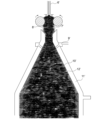
- the fiber columns meander while inscribed in the inverted funnel-shaped portion (10), spreading radially, spreading over the entire cylindrical portion (16), and being compressed and layered to become a compressed fiber mass.
- the angle of the funnel appropriate (e.g., 20 to 120 degrees) and smoothing the connection between the narrow path and the cylindrical portion, it is possible to prevent reversal of the layering order of the buckled and crimped fiber columns.
- a preferred angle is 25 to 90 degrees, and a more preferred angle is 30 to 60 degrees.
- the piston (13) slowly retreats in the axial direction in response to the growth of the compressed fiber mass, allowing for continuous production of compressed fiber mass.
- vibrations ranging from low frequency to ultrasonic range are applied to the compressed fiber mass in the axial direction through the piston (13), a dramatically high repeated impact load can be applied without significantly affecting the feed of the buckled and crimped fiber column at the entrance of the compression chamber. That is, if there are large voids remaining in the compressed fiber mass and the temperature is above the second-order transition point, the compressed fiber mass has strong plasticity, so the vibrations are rapidly attenuated within it and hardly reach the entrance of the compression chamber. That is, the vibrations significantly increase the apparent density without inhibiting the axial growth of the compressed fiber mass, and also make it possible to make the compressed fiber mass into a cake-like shape.
- acceleration proportional to the square of the frequency is transmitted from the piston as vibration stress, further compressing the compressed fiber mass into a cake-like shape.
- the lubrication state is improved at the interface where the compression chamber wall and the compressed fiber mass are in contact, resulting in a friction reduction effect and enabling the fiber cake to move smoothly.
- the back pressure can be adjusted by the feed speed of the rollers (14), and the cake density can be adjusted by the retreat speed of the piston (13). If the retreat speed of the piston (13) is too low, it becomes difficult for the rollers (14) to smoothly feed the buckled and crimped fiber columns, but it is easy to experimentally adjust the retreat speed of the piston (13) so as to maximize the cake density without causing this problem.
- the cake growth rate by adjusting the cross-sectional area or shape of the downstream side of the compression chamber to provide an appropriate discharge resistance without using the piston (13).
- the cake can be made endless and can be cut to any length.
- the discharge resistance can be adjusted by providing a resistance member at the discharge section of the compression chamber or by the shape of the compression chamber, and the shape can also be adjusted from the outside if the compression chamber is given flexibility.
- vibration compression by the piston (13) is not used, it becomes difficult to increase the cake density.
- the friction between the compressed fiber mass and the compression chamber is too great and the feeding is not smooth, it is effective to give a slight expansion to the cylindrical portion (16) of the compression chamber.
- the degree of expansion can be easily determined experimentally, but is usually 5 degrees or less, and preferably 3 degrees or less. If it is desired to avoid expansion of the cylindrical portion (16) in order to maintain the uniformity of the apparent density within the cake, the amount of oil and lubricity can be adjusted to promote the movement of the compressed fiber mass.
- the density of the fiber cake is uniquely determined by the feed speed of the buckled and crimped fiber column and the retreat speed of the piston (13). If the retreat speed of the piston (13) is increased, the density of the fiber cake decreases, and if it is decreased, the density increases, but if it is made too slow, it becomes difficult to feed the buckled and crimped fiber column. Therefore, the fiber cake is produced at as low a retreat speed as possible while checking the feed speed of the buckled and crimped fiber column and the retreat speed of the piston.
- the fiber material can be maintained above the secondary transition point in the compression chamber and the plasticity of the fiber mass can be maintained, it will be possible to mold it into a cake with a high apparent density. For this reason, it is desirable to provide a heater or jacket for temperature control in part or all of the area around the compression chamber.
- the melting point of polyethylene terephthalate fiber is around 260°C, but the secondary transition point is around 80°C, so it is desirable for the temperature inside the compression chamber to be around 80-160°C.
- the spun fibers are not given the opportunity to cool below the secondary transition point before they are buckled and crimped and compressed into a cake. If they are allowed to cool along the way, the crystal structure of the fibers will be solidified during the cooling process, and even if they are subsequently buckled and crimped, the processed yarn will remember the structure it had at the time of cooling and will attempt to return to its original structure in response to physical and chemical stimuli during subsequent processing and use.
- the crimped and compressed yarn of the present invention is crimped and compressed at a highly plastic stage before cooling, and does not return to its original structure as described above, which makes it different from traditional buckled and crimped processed yarn.
- indentations may occur on the fiber surface as a result of the compression baking process. This is also because the fibers are compression baked in a highly plastic state. The indentations are not noticeable in the form of single fibers, but when the fibers are made into, for example, filament woven fabric, they have the effect of reducing the inorganic gloss.
- the inner surface of the compression chamber is preferably a low-friction surface, at least in the axial direction.
- it may be a mirror finish or a matte finish.
- at least a part of the cylindrical portion (16) may be made to have a gently diverging structure.
- the compression chamber is preferably constructed with at least two removable cylindrical containers connected in series. When the downstream tube becomes full of cake, it can be separated as a fiber package and replaced with an empty tube.
- the cross section of the cylindrical compression chamber may be approximately circular or approximately polygonal.
- a circle is the simplest, but a triangular, rectangular or hexagonal polygon has the advantage that it can be packed without gaps when packaging.
- the upstream reverse funnel portion (10) is structured to be smoothly connected (i.e., the fibers do not get caught) regardless of the shape of the cylindrical portion (16).
- dyeing spots may occur in the corners of the approximately polygonal shape of the buckled and crimped processed yarn, but if this is intentionally used, it is possible to give the yarn an irregular shape that is irregular and non-periodic without fineness unevenness. It is extremely difficult to achieve such irregularity while also achieving high productivity of the fiber using yarn-making technology using a winder.
- the approximately polygonal shape does not necessarily have to be the entire compression chamber, and only the part that can be separated as a package may be used, or other changes are possible.
- Various shapes such as an ellipse can also be adopted.
- the key is to have a structure that does not impede the smooth feeding of the cake.
- a high-frequency impact is applied from the downstream side of the package to the upstream side by a piston (13).
- This impact is of the same quality as the impact commonly used in impact tools, for example.
- the impact is absorbed by the plasticity of the cake (usually 200 mm or more in major diameter) and the friction between the cake and the compression chamber wall, and the piston (13) moves slowly downstream by the amount of cake growth while applying the impact, so the growth of the cake is not hindered.
- the apparent specific gravity will be, for example, about 0.3 to 0.6.
- This value is converted into a package weight of 100 mm ⁇ x 300 mm, which is about 700 to 1,400 g, and is at a fully practical level. In fact, it can be said to be exceptionally compact for a package of buckling and crimping processed yarn.
- the cross-sectional area of the tubular portion (16) is determined according to the size of the package required for use. Small packages can be easily made because it is easy to change. For example, if the cake is 5 cm in diameter, 10 cm in length, and has an apparent density of 0.4 g/cm3, the package weight will be 78.5 g, which is equivalent to a length of about 7 km for 100D filament yarn. If this is folded in half, it becomes 3.5 km. It is estimated that there is a considerable need for such ends. On the other hand, it is not difficult to make the diameter 10 cm or more if necessary.
- polyester fibers have a remarkable characteristic of high-speed spinning.
- polyester fibers have a high degree of crystallinity overall, but low amorphous orientation and high crystalline orientation.
- the strength is 3-4 g/d and the elongation is about 30-50%, which is insufficient for some industrial fields that require high strength, but is strong enough for clothing and batting.
- Low amorphous orientation improves dyeability, and high crystalline orientation affects the morphological stability of the fibers.
- fibers produced by traditional methods that require a low spinning speed and separate drawing can easily achieve high strength and high initial modulus, but when relaxed in the subsequent processing process, an undesirable primary yield point occurs around 1 g/d on the SS curve, which is likely to cause problems with dimensional stability.
- the solidification of the spun fiber and the buckling crimping process are almost simultaneous, so it is assumed that the buckling crimping process is carried out in the middle of fixing the fiber structure, which is ideal for improving the fastness of the crimp.
- the fact that the indentation on the fiber surface is noticeable at the compression cake stage is assumed to be deeply related to the fact that the fiber structure is in the middle of fixing at the time of indentation formation.
- the indentation on the fiber surface gives a subtle matte effect to the final product.
- the crimped compressed yarn of the present invention is crimped and compressed at a stage of high plasticity before cooling, and is different from traditional buckling crimp processed yarn that is buckled and crimped after cooling once.
- the above effects are basically the same for both the pressurized gas chamber method and the suction gun method.
- the spun fibers are pulled up while in contact with the inner wall of the suction gun after solidification
- the spun fibers are usually pulled up without contacting the inner wall of the pores, which has the advantage that the buckling and crimping process can be carried out in a state of lower solidification. This means that a higher temperature can be maintained in the fiber processing cycle, and higher crimp fastness can be achieved.
- Spinning material Polyethylene terephthalate IV 0.68 Cap temperature: 300°C Base (1) 0.25 ⁇ 48H Discharge rate: 120G/min Size of the cylindrical part of the compressed air chamber: 150 ⁇ x 1.5m, 150 ⁇ x 100mm porous metal placed at the bottom end of the cylindrical part (16) Angle of the funnel-shaped part (10) of the compressed air chamber: 60 degrees Compressed air: 300kPaG, 30°C Narrow hole (6) connects a 3 ⁇ x300mm path and a 7 ⁇ x70mm path. 12 matte-finished chrome-plated piano wires, 1 ⁇ x60mm, are installed downstream and coaxially with the narrow hole (6) so that the inscribed circle is 8mm.
- Inverted funnel-shaped part (10) has an angle of 60 degrees, and the upper end is connected to an inverted funnel shape via a 30R curve from an 11mm ⁇ cylinder that circumscribes the lower 5mm of the piano wire of the narrow path, and the lower end inner surface is connected to the cylindrical part (16) of the compression container via a 30R curve.
- the cylindrical part of the compression container has an inner diameter of 100 ⁇ x 400mm and can be attached and detached at a point 200mm from the upstream side.
- the connecting surfaces of the upstream and downstream parts are funnel-shaped surfaces facing downward at 60 degrees to prevent fibers from getting caught.
- the impact piston is cylindrical with a diameter of 99.5 ⁇ and the compression container side has a flat surface perpendicular to its axis. Impact strength, stroke, and period: 80kg, 2mm, 10 c/sec Temperature inside the compression vessel: 110°C
- the take-up speed reaches approximately 6,000 m.
- the downstream compression vessel was filled with a 150 mm cake, the vessel could be replaced for continuous operation. It was possible to continuously unwind the buckled crimped yarn from the fiber cake.
- FIG. 1 shows an example of an apparatus for spinning, taking up, buckling and crimping, and compressing, and its state.
- FIG. 2 shows the state in which the taken-up yarn becomes a buckled, crimped fiber column and is fed to the compression chamber.
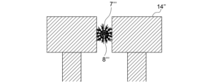
- FIG. 3 shows how the feed rate of the buckled, crimped fiber column is adjusted by rollers.
- FIG. 4 shows how the feed speed of the buckled and crimped fiber column is adjusted by rollers.
- FIG. 5 shows a state in which the downstream side of the cylindrical containers connected in series is separated as a package.
- FIG. 6 shows the state in which the crimped yarn is unwound from the cake through a guide.
- the method of the present invention can safely and inexpensively produce a buckled crimped yarn cake that can be unwound in one go from the spun raw material.
- the crimped yarn of the present invention is caked in a buckled state, so the unwound yarn has excellent bulk and crimp fastness, and is suitable for the production of bulky sheets.
- the cake of the present invention can be divided in the axial direction, so there is no need to rewind it when dividing it into smaller pieces, meaning that extremely small packages can be easily produced.
- the packaging device of the present invention is simple, so it is suitable for the production of a wide variety of products in small quantities.
- the fiber obtained by the present invention does not undergo a roller drawing process, so although it is not high strength, it does not recover when relaxed and has excellent dimensional stability. Although flat yarn cannot be obtained by the method of the present invention, the versatility of the fiber is not impaired by the presence of original crimp, as is the case with wool and cotton yarn.
Landscapes
- Engineering & Computer Science (AREA)
- Textile Engineering (AREA)
- Mechanical Engineering (AREA)
- Chemical & Material Sciences (AREA)
- Chemical Kinetics & Catalysis (AREA)
- General Chemical & Material Sciences (AREA)
- Spinning Methods And Devices For Manufacturing Artificial Fibers (AREA)
Priority Applications (4)
| Application Number | Priority Date | Filing Date | Title |
|---|---|---|---|
| JP2025520520A JPWO2024237129A1 (https=) | 2023-05-18 | 2024-05-07 | |
| CN202480031888.7A CN121152910A (zh) | 2023-05-18 | 2024-05-07 | 能够退绕的压曲卷曲纱饼的制造方法、用于该制造方法的制造装置以及能够退绕的压曲卷曲纱饼 |
| KR1020257038202A KR20260012715A (ko) | 2023-05-18 | 2024-05-07 | 풀림 가능한 좌굴권축사(座屈捲縮絲) 케이크의 제조 방법, 그를 위한 제조 장치 및 풀림 가능한 좌굴권축사 케이크 |
| EP24807082.3A EP4715100A1 (en) | 2023-05-18 | 2024-05-07 | Method for producing releasable buckled crimped yarn cake, apparatus for producing the same, and releasable buckled crimped yarn cake |
Applications Claiming Priority (2)
| Application Number | Priority Date | Filing Date | Title |
|---|---|---|---|
| JP2023082035 | 2023-05-18 | ||
| JP2023-082035 | 2023-05-18 |
Publications (1)
| Publication Number | Publication Date |
|---|---|
| WO2024237129A1 true WO2024237129A1 (ja) | 2024-11-21 |
Family
ID=93519595
Family Applications (1)
| Application Number | Title | Priority Date | Filing Date |
|---|---|---|---|
| PCT/JP2024/016942 Ceased WO2024237129A1 (ja) | 2023-05-18 | 2024-05-07 | 解舒可能な座屈捲縮糸ケークの製造方法、そのための製造装置及び解舒可能な座屈捲縮糸ケーク |
Country Status (5)
| Country | Link |
|---|---|
| EP (1) | EP4715100A1 (https=) |
| JP (1) | JPWO2024237129A1 (https=) |
| KR (1) | KR20260012715A (https=) |
| CN (1) | CN121152910A (https=) |
| WO (1) | WO2024237129A1 (https=) |
Citations (9)
| Publication number | Priority date | Publication date | Assignee | Title |
|---|---|---|---|---|
| US3707593A (en) | 1970-04-01 | 1972-12-26 | Toray Industries | Apparatus and method for manufacturing continuous filaments from synthetic polymers |
| JPS5132826A (ja) * | 1974-09-13 | 1976-03-19 | Toyo Boseki | Horiesuterusenikenshukuto no seizoho |
| JPS5288608A (en) * | 1976-01-20 | 1977-07-25 | Teijin Ltd | Method for collecting synthetic fiber tows |
| JPS5296222A (en) | 1976-02-10 | 1977-08-12 | Toray Ind Inc | Production of cylindrical fiber packages |
| JPS5338736A (en) * | 1976-07-16 | 1978-04-10 | Barmag Barmer Maschf | Crimping apparatus |
| JPS5446924A (en) | 1977-09-19 | 1979-04-13 | Toray Ind Inc | Production of crimped filament yarns and its device |
| JPS5598061A (en) | 1979-01-18 | 1980-07-25 | Toray Ind Inc | Fiber pile package and its manufacture |
| JPS5598933A (en) * | 1979-01-18 | 1980-07-28 | Toray Industries | Synthetic fiber sewing yarn |
| JPH01117179A (ja) | 1988-09-09 | 1989-05-10 | Toray Ind Inc | 糸条糸掛装置 |
-
2024
- 2024-05-07 JP JP2025520520A patent/JPWO2024237129A1/ja active Pending
- 2024-05-07 EP EP24807082.3A patent/EP4715100A1/en active Pending
- 2024-05-07 CN CN202480031888.7A patent/CN121152910A/zh active Pending
- 2024-05-07 KR KR1020257038202A patent/KR20260012715A/ko active Pending
- 2024-05-07 WO PCT/JP2024/016942 patent/WO2024237129A1/ja not_active Ceased
Patent Citations (10)
| Publication number | Priority date | Publication date | Assignee | Title |
|---|---|---|---|---|
| US3707593A (en) | 1970-04-01 | 1972-12-26 | Toray Industries | Apparatus and method for manufacturing continuous filaments from synthetic polymers |
| JPS5132826A (ja) * | 1974-09-13 | 1976-03-19 | Toyo Boseki | Horiesuterusenikenshukuto no seizoho |
| JPS5288608A (en) * | 1976-01-20 | 1977-07-25 | Teijin Ltd | Method for collecting synthetic fiber tows |
| JPS5296222A (en) | 1976-02-10 | 1977-08-12 | Toray Ind Inc | Production of cylindrical fiber packages |
| GB1574464A (en) | 1976-02-10 | 1980-09-10 | Toray Industries | Package of multifilament yarn and a method for producing such package |
| JPS5338736A (en) * | 1976-07-16 | 1978-04-10 | Barmag Barmer Maschf | Crimping apparatus |
| JPS5446924A (en) | 1977-09-19 | 1979-04-13 | Toray Ind Inc | Production of crimped filament yarns and its device |
| JPS5598061A (en) | 1979-01-18 | 1980-07-25 | Toray Ind Inc | Fiber pile package and its manufacture |
| JPS5598933A (en) * | 1979-01-18 | 1980-07-28 | Toray Industries | Synthetic fiber sewing yarn |
| JPH01117179A (ja) | 1988-09-09 | 1989-05-10 | Toray Ind Inc | 糸条糸掛装置 |
Also Published As
| Publication number | Publication date |
|---|---|
| KR20260012715A (ko) | 2026-01-27 |
| CN121152910A (zh) | 2025-12-16 |
| EP4715100A1 (en) | 2026-03-25 |
| JPWO2024237129A1 (https=) | 2024-11-21 |
Similar Documents
| Publication | Publication Date | Title |
|---|---|---|
| US6572798B2 (en) | Apparatus and method for spinning a multifilament yarn | |
| US6054216A (en) | Meltblown yarn | |
| US3707593A (en) | Apparatus and method for manufacturing continuous filaments from synthetic polymers | |
| US2750653A (en) | Yarn structure | |
| JP4192041B2 (ja) | 炭素繊維前駆体繊維束の製造方法及び製造装置 | |
| JPH0115603B2 (https=) | ||
| JPH086203B2 (ja) | 熱可塑性合成繊維の製造方法 | |
| DE19535143A1 (de) | Vorrichtung und Verfahren zur thermischen Behandlung von Fasern | |
| US4016329A (en) | Multifilament | |
| JP4101869B2 (ja) | フィラメントの溶融紡糸方法 | |
| EP0726338A2 (de) | Verfahren zur Herstellung eines multifilen Fadens | |
| US3734803A (en) | Apparatus for splaying and depositing nonwoven filamentary structures | |
| US6824717B2 (en) | Method for melt spinning filament yarns | |
| US4691003A (en) | Uniform polymeric filaments | |
| US4368232A (en) | Glass fiber mat and method of preparation thereof | |
| US5310514A (en) | Process and spinning device for making microfilaments | |
| TW555903B (en) | Process and device for the transport of continuous moldings without tensile stress | |
| CN113913951A (zh) | 一种熔喷微纳米纤维喷毛纱的纺纱装置 | |
| WO2024237129A1 (ja) | 解舒可能な座屈捲縮糸ケークの製造方法、そのための製造装置及び解舒可能な座屈捲縮糸ケーク | |
| US4004406A (en) | Spun type yarn and process for manufacturing the same | |
| US4024611A (en) | Method and apparatus for texturizing continuous filaments | |
| CA1053886A (en) | Method and apparatus for texturizing yarn | |
| CA2280872A1 (en) | Drawing device and method for producing drawn synthetic filaments | |
| US3264384A (en) | Process for producing a synthetic bast | |
| KR102263320B1 (ko) | 모노필라멘트 얀 제조 시스템 및 방법 |
Legal Events
| Date | Code | Title | Description |
|---|---|---|---|
| 121 | Ep: the epo has been informed by wipo that ep was designated in this application |
Ref document number: 24807082 Country of ref document: EP Kind code of ref document: A1 |
|
| ENP | Entry into the national phase |
Ref document number: 2025520520 Country of ref document: JP Kind code of ref document: A |
|
| WWE | Wipo information: entry into national phase |
Ref document number: 2025520520 Country of ref document: JP |
|
| WWE | Wipo information: entry into national phase |
Ref document number: 202517111486 Country of ref document: IN |
|
| WWP | Wipo information: published in national office |
Ref document number: 202517111486 Country of ref document: IN |
|
| WWE | Wipo information: entry into national phase |
Ref document number: 2024807082 Country of ref document: EP |
|
| NENP | Non-entry into the national phase |
Ref country code: DE |
|
| ENP | Entry into the national phase |
Ref document number: 2024807082 Country of ref document: EP Effective date: 20251218 |
|
| ENP | Entry into the national phase |
Ref document number: 2024807082 Country of ref document: EP Effective date: 20251218 |
|
| ENP | Entry into the national phase |
Ref document number: 2024807082 Country of ref document: EP Effective date: 20251218 |
|
| ENP | Entry into the national phase |
Ref document number: 2024807082 Country of ref document: EP Effective date: 20251218 |
|
| ENP | Entry into the national phase |
Ref document number: 2024807082 Country of ref document: EP Effective date: 20251218 |
|
| ENP | Entry into the national phase |
Ref document number: 2024807082 Country of ref document: EP Effective date: 20251218 |
|
| ENP | Entry into the national phase |
Ref document number: 2024807082 Country of ref document: EP Effective date: 20251218 |
|
| ENP | Entry into the national phase |
Ref document number: 2024807082 Country of ref document: EP Effective date: 20251218 |
|
| WWP | Wipo information: published in national office |
Ref document number: 2024807082 Country of ref document: EP |