WO2024236991A1 - ソーラーカーポート - Google Patents
ソーラーカーポート Download PDFInfo
- Publication number
- WO2024236991A1 WO2024236991A1 PCT/JP2024/015200 JP2024015200W WO2024236991A1 WO 2024236991 A1 WO2024236991 A1 WO 2024236991A1 JP 2024015200 W JP2024015200 W JP 2024015200W WO 2024236991 A1 WO2024236991 A1 WO 2024236991A1
- Authority
- WO
- WIPO (PCT)
- Prior art keywords
- water
- members
- rafter
- solar cell
- solar
- Prior art date
- Legal status (The legal status is an assumption and is not a legal conclusion. Google has not performed a legal analysis and makes no representation as to the accuracy of the status listed.)
- Pending
Links
Images


Classifications
-
- Y—GENERAL TAGGING OF NEW TECHNOLOGICAL DEVELOPMENTS; GENERAL TAGGING OF CROSS-SECTIONAL TECHNOLOGIES SPANNING OVER SEVERAL SECTIONS OF THE IPC; TECHNICAL SUBJECTS COVERED BY FORMER USPC CROSS-REFERENCE ART COLLECTIONS [XRACs] AND DIGESTS
- Y02—TECHNOLOGIES OR APPLICATIONS FOR MITIGATION OR ADAPTATION AGAINST CLIMATE CHANGE
- Y02B—CLIMATE CHANGE MITIGATION TECHNOLOGIES RELATED TO BUILDINGS, e.g. HOUSING, HOUSE APPLIANCES OR RELATED END-USER APPLICATIONS
- Y02B10/00—Integration of renewable energy sources in buildings
- Y02B10/10—Photovoltaic [PV]
-
- Y—GENERAL TAGGING OF NEW TECHNOLOGICAL DEVELOPMENTS; GENERAL TAGGING OF CROSS-SECTIONAL TECHNOLOGIES SPANNING OVER SEVERAL SECTIONS OF THE IPC; TECHNICAL SUBJECTS COVERED BY FORMER USPC CROSS-REFERENCE ART COLLECTIONS [XRACs] AND DIGESTS
- Y02—TECHNOLOGIES OR APPLICATIONS FOR MITIGATION OR ADAPTATION AGAINST CLIMATE CHANGE
- Y02E—REDUCTION OF GREENHOUSE GAS [GHG] EMISSIONS, RELATED TO ENERGY GENERATION, TRANSMISSION OR DISTRIBUTION
- Y02E10/00—Energy generation through renewable energy sources
- Y02E10/50—Photovoltaic [PV] energy
Definitions
- the present invention relates to a solar carport.
- welded H-beams and welded T-beams made of steel with hot-dip galvanized surfaces for corrosion protection are widely used.
- welded H-beams made of steel are made by welding together three thick plates to form an H-shaped cross section, which makes them less lightweight and reduces transportability and workability.
- hot-dip galvanized steel is prone to corrosion due to rainwater, condensation, seawater splashes, etc., so there are problems with corrosion resistance.
- the present invention was made in consideration of the above situation, and aims to provide a solar carport that is lightweight and has excellent corrosion resistance.
- the present invention provides a solar carport comprising: a plurality of solar cell modules arranged in a first direction and a second direction perpendicular to the first direction; a plurality of rafter members arranged along the first direction at the lower end portions on both sides of the second direction of each of the solar cell modules so as to support the plurality of solar cell modules; and a plurality of water-permeable members arranged along the first direction between two of the rafter members adjacent in the second direction, the rafter members being lightweight steel members, the water-permeable members having a first water-permeable portion extending in the first direction between the two rafter members adjacent in the second direction and having a concave shape that opens upward, and a pair of flange portions extending outward from the upper end portions on both sides of the second direction of the first water-permeable portion, each of the pair of flange portions being sandwiched between the solar cell modules and the rafter members (Invention 1).
- the rafter members are made of lightweight steel shaped beams, which reduces the weight of the rafter members. As a result, the transportability and workability of the rafter members are improved. In addition, rainwater and other moisture can be drained from the carport through the first water passage part of the water passage part, and the upper surface of the rafter members is protected by the flange part of the water passage part, which suppresses corrosion of the rafter members due to rainwater, etc.
- the water-permeable member is an extruded member made of aluminum or an aluminum alloy (Invention 2).
- Aluminum or aluminum alloy shaped members have better corrosion resistance than steel shaped members with hot-dip galvanized surfaces. Furthermore, aluminum or aluminum alloy shaped members can be manufactured at lower cost than, for example, stainless steel shaped members. Therefore, according to this invention (Invention 2), corrosion of the water-permeable members due to rainwater, etc. is suppressed, and the cost of the water-permeable members can be reduced.
- the water-permeable member may further have a rail portion that extends in the first direction between two adjacent rafter members in the second direction and has a concave shape that opens downward, and the rail portion may be configured so that a fastening member can be inserted and held from both ends in the first direction (Invention 3).
- the fastening member can be used to attach accessories to the rail section, such as external lighting and rain gutters arranged along the second direction.
- the water-passing member may further have a pair of second water-passing portions extending outward from the respective end portions of the pair of flange portions, and each of the pair of second water-passing portions may extend in the first direction and have a concave shape that opens upward (Invention 4).
- moisture such as rainwater that seeps out from between the solar cell module and the flange portion can be discharged through the second water passage portion of the water passage member.
- the rafter members are made of lightweight steel shaped beams, which reduces the weight of the rafter members. As a result, the transportability and construction of the rafter members are improved. In addition, rainwater and other moisture can be discharged from the carport through the first water passage part of the water passage part, and the upper surface of the rafter members is protected by the flange part of the water passage part, which suppresses corrosion of the rafter members due to rainwater, etc.
- FIG. 1 is a schematic perspective view of a solar carport according to one embodiment of the present invention, viewed from below.
- 2 is a schematic perspective view of the solar carport of FIG. 1 viewed from above.
- FIG. 2 is a schematic cross-sectional view showing an example of a water-permeable member.
- 4 is a schematic cross-sectional view showing the water-permeable member of FIG. 3 together with a solar cell module and a rafter member. 4 is a schematic diagram showing an example in which an accessory is attached to the water-passing member of FIG. 3 .
- FIG. 6 is a side view of FIG. 5 .
- 10 is a schematic cross-sectional view showing another example of a water-permeable member.
- FIG. 8 is a schematic cross-sectional view showing the water-permeable member of FIG. 7 together with a solar cell module and a rafter member.
- 2A, 2B, and 2C are top and front views of the solar carport of FIG. 1.
- 2A is a partial side view of the solar carport in FIG. 1
- FIG. 2B is a view of FIG. 2A from direction A
- FIG. 2C is a view of FIG. 2A from direction B.
- FIG. 2 is a partial perspective view of the solar carport of FIG.
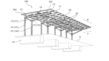
- FIG. 1 is a schematic perspective view of a solar carport 100 according to an embodiment of the present invention (hereinafter, simply referred to as "carport 100") as seen from below.
- Fig. 2 is a schematic perspective view of the carport 100 as seen from above.
- the carport 100 comprises a plurality of solar cell modules 11, a plurality of rafter members 12, a plurality of purlin members 13, a plurality of beam members 14, and a plurality of supports 15.
- the multiple solar cell modules 11 are arranged side by side in a first direction ⁇ and a second direction ⁇ perpendicular to the first direction ⁇ .
- the multiple rafter members 12 are arranged along the first direction ⁇ to support the multiple solar cell modules 11.
- the multiple purlin members 13 are arranged along the second direction ⁇ to support the multiple rafter members 12.
- the multiple beam members 14 are arranged along the first direction ⁇ to support the multiple purlin members 13.
- the multiple pillars 15 support the multiple beam members 14 and are erected on the ground G.
- the rafter member 12 is a lightweight steel beam. This reduces the weight of the rafter member 12. As a result, the transportability and construction of the rafter member 12 are improved.
- the carport 100 further includes a plurality of water-permeable members 16 arranged along the first direction ⁇ between two rafter members 12 adjacent to each other in the second direction ⁇ .
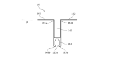
- FIG. 3 shows an example of a water-permeable member 16.
- FIG. 3 is a schematic cross-sectional view of the water-permeable member 16 in the second direction ⁇ .
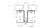
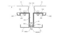
- FIG. 4 is a schematic cross-sectional view showing the water-permeable member 16 of FIG. 3 together with the solar cell module 11 and the rafter member 12.
- the multiple rafter members 12 are arranged along the lower ends 11a, 11b of each solar cell module 11 on both sides in the second direction ⁇ along the first direction ⁇ (direction perpendicular to the paper surface) to support the multiple solar cell modules 11.
- the water-permeable member 16 has a first water-permeable portion 161 that extends in the first direction ⁇ between two rafter members 12 adjacent in the second direction ⁇ and has a concave shape that opens upward, and a pair of flange portions 162 that extend outward from the upper end portion 161a on both sides of the first water-permeable portion 161 in the second direction ⁇ . As shown in FIG. 4, each of the pair of flange portions 162 is sandwiched between the solar cell module 11 and the rafter member 12.
- moisture such as rainwater can be discharged from the carport 100 through the first water-permeable portion 161 of the water-permeable member 16, and the upper surface portion 12a of the rafter member 12 is protected by the flange portion 162 of the water-permeable member 16, thereby suppressing corrosion of the rafter member 12 due to rainwater, etc.
- the length of the flange portion 162 in the second direction ⁇ is equal to or greater than the length of the upper surface portion 12a of the rafter member 12 in the second direction ⁇ .
- the length of the flange portion 162 in the second direction ⁇ may be equal to or greater than the length of the upper surface portion 12a of the rafter member 12 in the second direction ⁇ .
- the water-permeable member 16 is preferably an extruded shape made of aluminum or an aluminum alloy.
- the extruded shape is a shape manufactured by a hot extrusion method. According to the hot extrusion method, since the material is extruded through a die machined into various shapes, it is possible to manufacture shapes having complex shapes. Aluminum or aluminum alloy shapes are more corrosion-resistant than hot-dip galvanized steel shapes. In addition, aluminum or aluminum alloy shapes can be manufactured at a lower cost than, for example, stainless steel shapes. Therefore, when the water-permeable member 16 is an extruded shape made of aluminum or an aluminum alloy, corrosion of the water-permeable member 16 due to rainwater, etc. is suppressed. This further suppresses corrosion of the rafter member 12. In addition, the cost of the water-permeable member 16 can be reduced.
- the water-permeable member 16 may further have a rail portion 163 that extends in the first direction ⁇ between two rafter members 12 adjacent in the second direction ⁇ and has a concave shape that opens downward.
- the rail portion 163 is preferably configured so that the fastening member 60 can be inserted and held from both ends in the second direction ⁇ .
- the fastening member 60 can be used to attach an accessory 61, such as an external light or a rain gutter arranged along the second direction, to the rail portion 163.
- the first water passage portion 161 and the rail portion 163 have concave shapes that face each other in the vertical direction.
- the rail portion 163 may have a rail groove 163a extending in the first direction ⁇ through which the fastening member 60 can be inserted and held.
- the rail groove 163a may be formed by bending the lower end portions 163b on both sides of the rail portion 163 in the second direction ⁇ inward.
- the fastening member 60 is not particularly limited as long as it can fasten the rail portion 163 of the water-permeable member 16 and the accessory part 61.
- the fastening member 60 is, for example, a bolt having a head and a shaft, typically a hexagonal bolt 601.
- the rail portion 163 has a rail groove 163a extending in the first direction ⁇ into which the shaft portion 601b of the hexagonal bolt 601 can be inserted and into which the head portion 601a of the hexagonal bolt 601 can be held.
- the head portion 601a of the hexagonal bolt 601 is located inside the rail groove 163a, and the shaft portion 601b of the hexagonal bolt 601 is located outside the rail groove 163a.
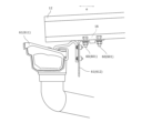
- FIG. 5 is a schematic diagram showing an example in which an accessory 61 is attached to the rail portion 163 of the water-permeable member 16 of FIG. 3 using a fastening member 60.
- FIG. 6 is a side view of FIG. 5.
- the accessory 61 includes a rain gutter 611 and a mounting bracket 612 for the rain gutter 611.
- the rain gutter 611 is arranged, for example, along the second direction ⁇ .
- the rain gutter 611 is attached to the rail portion 163 of the water-permeable member 16 by a hexagonal bolt 601 using the mounting bracket 612. As shown in FIG.
- Figure 7 is a schematic cross-sectional view showing another example of a water-permeable member 16.
- Figure 8 is a schematic cross-sectional view showing the water-permeable member 16 of Figure 7 together with a solar cell module 11 and a rafter member 12.
- the water-passing member 16 may further have a pair of second water-passing portions 164 extending outward from the end portions 162a of each of the pair of flange portions 162.
- Each of the pair of second water-passing portions 164 extends in the first direction ⁇ and has a concave shape that opens upward.
- the second water passage portion 164 is formed so that the cross section in the second direction ⁇ is an inverted trapezoid. Also, in the example shown in Figures 7 and 8, the depth of the second water passage portion 164 is smaller than the depth of the first water passage portion 161 in the cross section in the second direction ⁇ .
- the shape of the second water passage portion 164 is not limited to the example shown in Figures 7 and 8.
- the second water passage portion 164 may be formed so that the cross section is V-shaped.
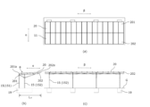
- Figure 9 shows a top view (a), a side view (b), and a front view (c) of the carport 100.
- Figure 10 shows a partial side view (a) of the carport 100, a view (b) of (a) from direction A, and a view (c) of (a) from direction B.
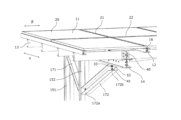
- Figure 11 is a partial perspective view of the carport 100.
- a plurality of solar cell modules 11 arranged in parallel in a first direction ⁇ and a second direction ⁇ constitute a roof member 20.
- the roof member 20 has a total of 30 solar cell modules 11 arranged in two rows along the first direction ⁇ and 15 rows along the second direction ⁇ .
- each solar cell module 11 may be a double-sided solar cell module in which multiple photoelectric conversion cells are arranged in a tile shape, sandwiched between reinforced glass, and the outer periphery of the glass is surrounded by an aluminum alloy frame.
- a pair of flange portions 162 of the water-permeable member 16 may be sandwiched between the frame of the solar cell module 11 and the rafter member 12.
- the frame of the solar cell module 11 and the rafter member 12 may be connected using a fastening member such as a hexagonal bolt.
- the roof member 20 is inclined with respect to the first direction ⁇ .
- the multiple solar cell modules 11 are arranged so that they are continuously inclined as a whole with respect to the first direction ⁇ .
- the inclination angle ⁇ of the roof member 20 is, for example, 2° or more and 10° or less.
- the inclination angle ⁇ may be 3°.
- the inclination angle ⁇ is 3°, direct light and scattered light can be efficiently guided to the solar cell module 11 while water such as rainwater can be efficiently discharged by the water-permeable member 16, so that dirt is less likely to accumulate on the surface of the solar cell module 11 due to the flow of rainwater, etc.
- the side of the roof member 20 where the distance from the ground G to the roof member 20 is small is called the rear side 201
- the side where the distance from the ground G to the roof member 20 is large is called the front side 202.
- the carport 100 has a structure in which the rear side 201 of the roof member 20 is cantilevered by multiple pillars 15. While the rear side 201 of the roof member 20 is supported by multiple pillars 15, there are no pillars 15 on the front side 202 of the roof member 20. With this structure, since there are no pillars 15 on the front side 202 of the roof member 20, vehicles can be easily loaded and unloaded from the carport 100. This improves the convenience of the carport 100.
- the support 15 has rear supports 151 and front supports 152.
- the rear supports 151 are erected vertically to the ground G in a row along the second direction ⁇ on the rear side 201 of the roof member 20, with a total of four of them.
- the ground G is a horizontal surface.
- the front supports 152 are erected vertically to the ground G in a row along the second direction ⁇ , closer to the front side 202 of the roof member 20 than the rear supports 151.
- the front support 152 is preferably installed at a position of 1/2 ⁇ L 20 or more from the end 202a of the front side 202, and more preferably at a position of 2/3 ⁇ L 20 or more.
- the rear support 151 is preferably installed at a position of L 20 from the end 202a of the front side 202.
- the front support 152 can be positioned at a position where the front support 152 is unlikely to interfere with driving when the vehicle is parked, and does not interfere with opening and closing the rear door of the parked vehicle while reliably supporting the roof member 20. Therefore, the convenience of the carport 100 is improved.
- a total of four beam members 14 are arranged in four rows along the first direction ⁇ .
- Each beam member 14 is supported by two pillars 15 (rear pillar 151 and front pillar 152) erected along the first direction ⁇ .
- the four beam members 14 are each supported by two pillars 15 (rear pillar 151 and front pillar 152) so as to be parallel to each other in the first direction ⁇ .
- a total of four purlin members 13 are arranged in four rows along the second direction ⁇ .
- the four purlin members 13 are supported by four beam members 14 arranged along the first direction ⁇ .
- the rafter members 12 are arranged along the first direction ⁇ at the lower ends 11a, 11b on both sides of the second direction ⁇ of each solar cell module 11.
- the solar cell modules 11 are arranged in 15 rows along the second direction ⁇ , so a total of 30 rafter members 12 are arranged.
- the 30 rafter members 12 are supported by four purlin members 13 arranged along the second direction ⁇ .
- the number and arrangement of the solar cell modules 11, rafter members 12, purlin members 13, beam members 14, and supports 15 are not limited to the above-mentioned examples.
- the carport 100 may further include a plurality of diagonal members 17 and a plurality of reinforcing members 18 (shown in FIG. 1).
- the diagonal members 17 are arranged diagonally in a vertical plane defined by the front support 152 and the beam member 14.
- the reinforcing members 18 are arranged diagonally in a horizontal plane defined by the purlin member 13 and the beam member 14.
- the diagonal member 17 has a rear diagonal member 171 and a front diagonal member 172.
- the rear diagonal member 171 may be arranged diagonally to connect the connection portion 31 located at a predetermined position in the vertical direction of the front support 152 to the connection portion 32 between the rear support 151 and the beam member 14.
- the front diagonal member 172 may be arranged diagonally to connect the connection portion 31 located at a predetermined position in the vertical direction of the front support 152 to the connection portion 33 located at a predetermined position in the first direction ⁇ of the beam member 14.
- the length of the front diagonal member 172 may be greater than the length of the rear diagonal member 171.
- the rear support 151, the front support 152, and the beam member 14 may be made of lightweight lip channel steels arranged back to back.
- the rear diagonal member 171 and the front diagonal member 172 may be made of lightweight channel steels arranged back to back.
- the reinforcing members 18 are also called braces. As shown in FIG. 1, the reinforcing members 18 may be arranged like a cross on the diagonals of a rectangle defined by the purlin members 13 and the beam members 14 within the horizontal plane of the rectangle. This structure can improve the horizontal strength of the carport 100.
- the carport 100 may further include a concrete foundation 19 formed on the ground G.
- a plurality of posts 15 may be erected on the concrete foundation 19. With this structure, the posts 15 are rigidly connected to the concrete foundation 19, so that the verticality of the posts 15 is restrained and the carport 100 as a whole can be prevented from tipping over.
- a gap (joint) 21 exists along the first direction ⁇ between solar cell modules 11 adjacent in the second direction ⁇ .
- the width of the gap 21 in the second direction ⁇ is not particularly limited and is, for example, 10 mm or more and 30 mm or less. Water such as rainwater flows from the gap 21 into the first water passage portion 161 of the water passage member 16 and is discharged.
- a gap (joint) 22 exists along the second direction ⁇ between solar cell modules 11 adjacent in the first direction ⁇ .
- the width of the gap 22 in the first direction ⁇ is not particularly limited, and is, for example, 10 mm or more and 30 mm or less.
- the gap 22 is sealed to prevent moisture such as rainwater from entering.
- the means for sealing the gap 22 is not particularly limited.
- a fitting member described in Patent No. 7141782 may be used as a means for sealing the gap 22.
- a commonly used gasket and waterproof seal may be used as a means for sealing the gap 22.
- the rafter member 12 and the purlin member 13 may be connected using a fastening member such as a hexagonal bolt.
- the purlin member 13 and the beam member 14 may be connected using a purlin bracket 40.
- the beam member 14 and the support column 15 may be connected using a fastening member 41.
- the fastening member 41 is, for example, a hexagonal bolt.
- the beam member 14 and the vertical upper end portion 152b of the front support 152 may be connected at a connection portion 30 located at a predetermined position in the second direction ⁇ of the beam member 14.
- a gusset plate 50 and fastening member 41 may be used for the connection.
- the gusset plate 50 is connected using the fastening member 41 while being sandwiched between the webs of the beam member 14, which is made of a back-to-back structure of light-gauge steel lip channel steel.
- the lower end 171a of the rear diagonal member 171 and the lower end 172a of the front diagonal member 172 may be connected to the front support 152 at a connection portion 31 located at a predetermined vertical position of the front support 152.
- a gusset plate 51 and a fastening member 41 may be used for the connection.
- the gusset plate 51 is connected using the fastening member 41 while being sandwiched between the webs of the front support 152, which is made of a back-to-back structure of light-gauge steel lip channel steel.
- the upper end 171b of the rear diagonal member 171 may be connected to the rear support 151 and the beam member 14.
- a gusset plate 52 and fastening member 41 may be used for the connection.
- the gusset plate 52 is connected using the fastening member 41 while being sandwiched between the webs of the rear support 151 and the beam member 14, which are made of back-to-back light-gauge steel lip channel steel.
- the upper end 172b of the front diagonal member 172 may be connected to the beam member 14 at a connection portion 33 located at a predetermined position in the first direction ⁇ of the beam member 14.
- a gusset plate 53 and a fastening member 41 may be used for the connection.
- the gusset plate 53 is connected using the fastening member 41 while being sandwiched between the webs of the beam member 14, which is made of a back-to-back structure of light-gauge steel lip channel steel.
- the purlin members 13, beam members 14, and pillars 15 are preferably made of lightweight steel. In this case, the weight of each member can be reduced, and the transportability and construction of each member is improved. In addition, by constructing the pillars 15 and beam members 14 with lightweight steel back to back, the gusset plates 51, 52, and 53 can be sandwiched between the webs of the lightweight steel, eliminating the need for welding and improving the manufacturability of each member.
- the main members 13, beam members 14, and supports 15 may be steel sheets that have been treated with a highly corrosion-resistant pre-plating.
- Highly corrosion-resistant pre-plating has a thinner plating layer than hot-dip galvanizing, but has higher corrosion resistance than hot-dip galvanizing. Therefore, even if steel sheets that have been highly corrosion-resistant pre-plating in a factory are bent, there is an advantage that the plating is less likely to crack or peel off.
- hot-dip galvanizing is performed after bending, the processed part will return and deform due to the heat of the plating tank, but steel sheets that have been treated with highly corrosion-resistant pre-plating do not return and have excellent shape precision.
- highly corrosion-resistant pre-plating does not cause uneven plating or sagging like hot-dip galvanizing, so the surface is smooth, improving the commercial value of buildings that place importance on design, such as carports.
- the solar carport of the present invention is lightweight and has excellent corrosion resistance, making it useful in the technical fields of solar cell modules and carports.
- Reference Signs List 100 Solar carport 11 Solar cell module 12 Rafter member 13 Purlin member 14 Beam member 15 Support 151 Rear support 152 Front support 16 Water passage member 161 First water passage portion 162 Flange portion 163 Rail portion 163a Rail groove 164 Second water passage portion 17 Diagonal member 171 Rear diagonal member 172 Front diagonal member 18 Reinforcement member 19 Concrete foundation 20 Roof member 201 Rear side 202 Front side 21, 22 Gap 30, 31, 32, 33 Connection portion 40 Purlin support bracket 41 Fastening member 50, 51, 52, 53 Gusset plate 60 Fastening member 601 Hexagon bolt 601a Head 601b Shaft portion 61 Accessory part 611 Rain gutter 612 Mounting bracket ⁇ First direction ⁇ Second direction ⁇ Incline angle G Ground
Landscapes
- Roof Covering Using Slabs Or Stiff Sheets (AREA)
- Photovoltaic Devices (AREA)
Priority Applications (1)
| Application Number | Priority Date | Filing Date | Title |
|---|---|---|---|
| CN202480020489.0A CN120937244A (zh) | 2023-05-16 | 2024-04-16 | 太阳能车棚 |
Applications Claiming Priority (2)
| Application Number | Priority Date | Filing Date | Title |
|---|---|---|---|
| JP2023081149A JP7710745B2 (ja) | 2023-05-16 | 2023-05-16 | ソーラーカーポート |
| JP2023-081149 | 2023-05-16 |
Publications (1)
| Publication Number | Publication Date |
|---|---|
| WO2024236991A1 true WO2024236991A1 (ja) | 2024-11-21 |
Family
ID=93518938
Family Applications (1)
| Application Number | Title | Priority Date | Filing Date |
|---|---|---|---|
| PCT/JP2024/015200 Pending WO2024236991A1 (ja) | 2023-05-16 | 2024-04-16 | ソーラーカーポート |
Country Status (3)
| Country | Link |
|---|---|
| JP (1) | JP7710745B2 (enExample) |
| CN (1) | CN120937244A (enExample) |
| WO (1) | WO2024236991A1 (enExample) |
Citations (7)
| Publication number | Priority date | Publication date | Assignee | Title |
|---|---|---|---|---|
| JP2012188807A (ja) * | 2011-03-08 | 2012-10-04 | Sekisui Chem Co Ltd | 太陽光発電装置付き屋根およびこれを備えたカーポート |
| JP2013157478A (ja) * | 2012-01-30 | 2013-08-15 | Sharp Corp | 太陽光発電ユニットおよび太陽光発電システム |
| JP2013213317A (ja) * | 2012-03-30 | 2013-10-17 | Lixil Corp | 屋根構造体 |
| JP2014051824A (ja) * | 2012-09-07 | 2014-03-20 | Nihon Roof Kenzai Kk | 光起電建造物およびその製造方法 |
| WO2014076954A1 (ja) * | 2012-11-14 | 2014-05-22 | 三洋電機株式会社 | 太陽電池モジュール群 |
| US20210041144A1 (en) * | 2018-01-19 | 2021-02-11 | Aaron Eriksson | Systems and methods for solar panel mounting |
| WO2023276124A1 (ja) * | 2021-07-01 | 2023-01-05 | ネクストエナジー・アンド・リソース株式会社 | カーポート |
-
2023
- 2023-05-16 JP JP2023081149A patent/JP7710745B2/ja active Active
-
2024
- 2024-04-16 CN CN202480020489.0A patent/CN120937244A/zh active Pending
- 2024-04-16 WO PCT/JP2024/015200 patent/WO2024236991A1/ja active Pending
Patent Citations (7)
| Publication number | Priority date | Publication date | Assignee | Title |
|---|---|---|---|---|
| JP2012188807A (ja) * | 2011-03-08 | 2012-10-04 | Sekisui Chem Co Ltd | 太陽光発電装置付き屋根およびこれを備えたカーポート |
| JP2013157478A (ja) * | 2012-01-30 | 2013-08-15 | Sharp Corp | 太陽光発電ユニットおよび太陽光発電システム |
| JP2013213317A (ja) * | 2012-03-30 | 2013-10-17 | Lixil Corp | 屋根構造体 |
| JP2014051824A (ja) * | 2012-09-07 | 2014-03-20 | Nihon Roof Kenzai Kk | 光起電建造物およびその製造方法 |
| WO2014076954A1 (ja) * | 2012-11-14 | 2014-05-22 | 三洋電機株式会社 | 太陽電池モジュール群 |
| US20210041144A1 (en) * | 2018-01-19 | 2021-02-11 | Aaron Eriksson | Systems and methods for solar panel mounting |
| WO2023276124A1 (ja) * | 2021-07-01 | 2023-01-05 | ネクストエナジー・アンド・リソース株式会社 | カーポート |
Also Published As
| Publication number | Publication date |
|---|---|
| CN120937244A (zh) | 2025-11-11 |
| JP2024165210A (ja) | 2024-11-28 |
| JP7710745B2 (ja) | 2025-07-22 |
Similar Documents
| Publication | Publication Date | Title |
|---|---|---|
| US20240348193A1 (en) | Device for attaching to a noise barrier | |
| JP3198411U (ja) | 太陽電池パネル屋根兼用型カーポート | |
| JP2015028288A (ja) | 屋根パネル及び建物の屋根構造 | |
| JP7710745B2 (ja) | ソーラーカーポート | |
| JP2002021266A (ja) | 陸屋根構造 | |
| JP2018003244A (ja) | 屋根パネルおよび建物の屋根構造 | |
| JP6441564B2 (ja) | 太陽電池モジュール及び屋根 | |
| CN218541218U (zh) | 光伏屋顶的水槽主梁一体化结构 | |
| CN215330420U (zh) | 屋顶结构、屋顶和墙立柱连接结构、房屋骨架及房屋 | |
| JP2025123628A (ja) | 簡易建物 | |
| JP2024109815A (ja) | パネル体付き構造物 | |
| JP2016141971A (ja) | Pvカーポート | |
| JP3940386B2 (ja) | 太陽エネルギー装置架設構造 | |
| JP7364294B1 (ja) | 屋根構造体及び屋根構造体の施工方法 | |
| JP7164394B2 (ja) | 軒樋付き屋根構造体 | |
| JP3414711B2 (ja) | 太陽電池パネル付バルコニー | |
| CN219343811U (zh) | 应用于光伏棚的一体化c型主梁水槽 | |
| CN112746759A (zh) | 一种预制舱顶盖防雨结构及预制舱 | |
| KR102729203B1 (ko) | 발전효율 및 내풍압성이 개선된 건물형 태양광모듈 지지구조 및 이의 시공방법 | |
| CN223423383U (zh) | 一种快拼式钢结构模块建筑屋面安装结构 | |
| CN221095967U (zh) | 一种新型的棚上棚bipv支架结构 | |
| JP7779564B1 (ja) | 太陽電池モジュールのフレーム、太陽電池モジュールの取付具、および太陽電池モジュールの取付構造 | |
| CN221703323U (zh) | 一种光伏bipv一体式厂房 | |
| US12119780B1 (en) | Mounting bracket system for solar panels and solar panel comprising the same | |
| JPH0230573Y2 (enExample) |
Legal Events
| Date | Code | Title | Description |
|---|---|---|---|
| 121 | Ep: the epo has been informed by wipo that ep was designated in this application |
Ref document number: 24806945 Country of ref document: EP Kind code of ref document: A1 |