WO2024236912A1 - 故障検知回路および故障検知方法 - Google Patents
故障検知回路および故障検知方法 Download PDFInfo
- Publication number
- WO2024236912A1 WO2024236912A1 PCT/JP2024/012425 JP2024012425W WO2024236912A1 WO 2024236912 A1 WO2024236912 A1 WO 2024236912A1 JP 2024012425 W JP2024012425 W JP 2024012425W WO 2024236912 A1 WO2024236912 A1 WO 2024236912A1
- Authority
- WO
- WIPO (PCT)
- Prior art keywords
- current
- predetermined
- circuit
- value
- control circuit
- Prior art date
- Legal status (The legal status is an assumption and is not a legal conclusion. Google has not performed a legal analysis and makes no representation as to the accuracy of the status listed.)
- Ceased
Links
Images




Classifications
-
- G—PHYSICS
- G01—MEASURING; TESTING
- G01R—MEASURING ELECTRIC VARIABLES; MEASURING MAGNETIC VARIABLES
- G01R19/00—Arrangements for measuring currents or voltages or for indicating presence or sign thereof
-
- G—PHYSICS
- G01—MEASURING; TESTING
- G01R—MEASURING ELECTRIC VARIABLES; MEASURING MAGNETIC VARIABLES
- G01R31/00—Arrangements for testing electric properties; Arrangements for locating electric faults; Arrangements for electrical testing characterised by what is being tested not provided for elsewhere
-
- G—PHYSICS
- G01—MEASURING; TESTING
- G01R—MEASURING ELECTRIC VARIABLES; MEASURING MAGNETIC VARIABLES
- G01R35/00—Testing or calibrating of apparatus covered by the other groups of this subclass
Definitions
- This disclosure relates to a fault detection circuit and a fault detection method for detecting a fault in a current sensor.
- Patent document 1 describes a system that causes a fuse to cut off a current path based on the current value detected by a current sensor.
- the present disclosure provides a fault detection circuit that can detect faults in a current sensor without installing multiple current sensors.
- the fault detection circuit disclosed herein is a fault detection circuit that detects a fault in a current sensor that detects a current flowing through a current path connecting a power source and a load, and includes a current source and a control circuit, the current source flows a current of a predetermined current value to a current detection portion in the current path where the current sensor detects a current, and the control circuit detects a fault in the current sensor based on the current value of the current detected by the current sensor when the current of the predetermined current value flows to the current detection portion.
- the fault detection method disclosed herein is a fault detection method executed by a fault detection circuit that detects a fault in a current sensor that detects a current flowing through a current path connecting a power source and a load, the fault detection circuit having a current source, and the fault detection method includes the steps of: flowing a current of a predetermined current value from the current source to a current detection portion in the current path where the current sensor detects a current; and detecting a fault in the current sensor based on the current value of the current detected by the current sensor when the current of the predetermined current value is flowed to the current detection portion.
- the failure detection circuit can detect a failure in a current sensor without providing multiple current sensors.
- FIG. 1 is a configuration diagram showing an example of a battery cutoff system according to a first embodiment
- 4 is a flowchart showing an example of the operation of the failure detection circuit according to the first embodiment
- FIG. 11 is a diagram for explaining a predetermined condition.
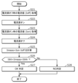
- 4 is a flowchart illustrating an example of a method for detecting a failure of a current sensor.
- 10 is a flowchart showing another example of a method for detecting a failure of a current sensor.
- FIG. 11 is a configuration diagram showing an example of a battery cutoff system according to a second embodiment.
- FIG. 11 is a configuration diagram showing a specific example of a battery cutoff system according to a second embodiment.
- 11 is a configuration diagram showing a specific example of a battery cutoff system according to a third embodiment.
- 13 is a flowchart showing an example of the operation of the failure detection circuit and a host ECU according to the third embodiment; 13 is a flowchart illustrating an example of a failure detection method according to another embodiment.
- FIG. 1 is a configuration diagram showing an example of a battery cutoff system 2 according to the first embodiment.
- the battery cutoff system 2 is used in a transport device that includes an HV battery (High Voltage battery) 1 and a load 3.
- FIG. 1 also shows the HV battery 1 and the load 3 that are provided in the transport device.
- the HV battery 1 and the load 3 are provided outside the battery cutoff system 2.
- the battery cutoff system 2 is used in the transport device, for example, an electric vehicle.
- the HV battery 1 is, for example, a power source capable of applying a high voltage (e.g., several hundreds of volts) to the load 3.
- the HV battery 1 is a main battery (e.g., a lithium-ion battery) in an electric vehicle.
- the load 3 is, for example, the motor and inverter of an electric vehicle.
- the electric vehicle is driven by power being supplied from the HV battery 1 to the load 3.
- a large current flows through the current path 200 connecting the HV battery 1 and the load 3 due to a short circuit, which may cause the HV battery 1 to smoke or catch fire, and therefore the battery cutoff system 2 is used in the transportation equipment.
- the battery cutoff system 2 is a system for cutting off a current path 200 connecting the HV battery 1 and the load 3.
- the current path 200 may be a path connecting the positive terminal of the HV battery 1 and the positive terminal of the load 3, or a path connecting the negative terminal of the HV battery 1 and the negative terminal of the load 3.
- the current path 200 may be cut off by cutting a wiring (e.g., a bus bar) through which a current flows, or by turning off a relay that is inserted in the current path 200 and forms part of the current path 200.
- the battery cutoff system 2 includes a fault detection circuit 10, a current sensor 20, a cutoff device 30, a main relay 40, a sub-relay 41, a pre-charge relay 42, and a pre-charge resistor 43.
- the current sensor 20 is a sensor that detects the current flowing in the current path 200 that connects the HV battery 1 and the load 3.
- the current sensor 20 is a shunt type sensor that detects the current using a shunt resistor (e.g., several tens of ⁇ ).
- the current sensor 20 outputs information corresponding to the current value of the detected current (e.g., the voltage generated when a current flows through the shunt resistor) to the fault detection circuit 10.
- the current sensor 20 may be a non-contact type current sensor, and may detect the current using a Hall element or the like.
- Current sensor 20 detects the current flowing through current path 200 at current detection portion 210 in current path 200.
- the shunt resistor is inserted into current detection portion 210 in current path 200 and forms part of current path 200.
- the Hall element detects the magnetism generated by the current flowing through current detection portion 210 in current path 200.
- the interrupter 30 is a device for interrupting the current path 200 when a large current flows through the current path 200 due to a short circuit abnormality.
- the interrupter 30 is a pyrotechnic interrupter (irreversible interrupter, irreversible pyrotechnic interrupter), and interrupts the current path 200 by irreversibly cutting the current path 200 in the event of an abnormality.
- the interrupter 30 may be a mechanical relay inserted in the current path 200, and may interrupt the current path 200 by turning off the mechanical relay in the event of an abnormality.
- the interrupter 30 is provided in the current path 200 connecting the positive terminal of the HV battery 1 and the positive terminal of the load 3, and interrupts the current path 200 in response to a drive signal from the fault detection circuit 10.
- the main relay 40 and the sub-relay 41 are provided on a current path 200 that connects the HV battery 1 and the load 3, and when the main relay 40 and the sub-relay 41 are on, power can be supplied from the HV battery 1 to the load 3.
- the relay when the relay is on, it means that the relay is in a conductive state, and when the relay is off, it means that the relay is in a non-conductive state.
- the main relay 40 is provided on the current path 200 that connects the positive terminal of the HV battery 1 and the positive terminal of the load 3
- the sub-relay 41 is provided on the current path 200 that connects the negative terminal of the HV battery 1 and the negative terminal of the load 3.
- the battery cutoff system 2 is provided with a pre-charge relay 42 and a pre-charge resistor 43 as a measure against inrush current.
- the precharge relay 42 and the precharge resistor 43 are connected in series, and the circuit in which the precharge relay 42 and the precharge resistor 43 are connected in series is connected in parallel to the main relay 40.
- the main relay 40 when starting up the transport equipment, the main relay 40 is turned off, the sub-relay 41 is turned on, and the precharge relay 42 is turned on. This allows current to flow to the load 3 via the precharge resistor 43, thereby suppressing the occurrence of inrush current.
- the precharge relay 42 is turned off and the main relay 40 is turned on to start the operation of the load 3.
- the main relay 40, the sub-relay 41, and the precharge relay 42 are controlled by a host ECU (Electronic Control Unit) or the like provided outside the battery cutoff system 2.
- the battery cutoff system 2 may also include a voltage detection circuit that detects the voltage of the load 3 and the voltage of the HV battery 1.
- the fault detection circuit 10 is provided in a battery cutoff system 2 used in, for example, transportation equipment.
- the fault detection circuit 10 includes a control circuit 100, a cutoff control circuit 110, and a current source 140.
- the control circuit 100 and the cutoff control circuit 110 are realized, for example, by a microcontroller (MCU: Micro Controller Unit).
- the control circuit 100 and the cutoff control circuit 110 may also be realized, for example, by an ASIC (Application Specific Integrated Circuit).
- the control circuit 100, the cutoff control circuit 110, and the current source 140 are mounted on a single board to form the fault detection circuit 10.
- the current source 140 passes a current of a predetermined current value to the current detection portion 210 where the current sensor 20 in the current path 200 detects the current.
- the predetermined current value is not particularly limited, but is, for example, about several amperes.
- the current source 140 is connected in parallel with the current detection portion 210, and specifically, one end of the current source 140 is connected to one end 211 of the current detection portion 210 (e.g., one end of a shunt resistor in the current sensor 20), and the other end of the current source 140 is connected to the other end 212 of the current detection portion 210 (e.g., the other end of the shunt resistor in the current sensor 20). Since the resistance component of the current detection portion 210 is very small, the current of the predetermined current value from the current source 140 easily flows directly through the current detection portion 210.
- the control circuit 100 acquires the current value of the current flowing through the current path 200 detected by the current sensor 20.
- the control circuit 100 has an AD conversion function and converts the acquired current value (analog value) of the current into a digital value.
- the control circuit 100 determines whether or not to drive the interrupter 30 (i.e., to interrupt the current path 200) based on whether or not the current detected by the current sensor 20 is an overcurrent.
- the interruption control circuit 110 controls the interruption of the interrupting device 30, which interrupts the current flowing through the current path 200.
- the interruption control circuit 110 determines that the current flowing through the current path 200 is an overcurrent (i.e., when it determines that the interrupting device 30 should be driven)
- the interruption control circuit 110 outputs a drive signal to the interrupting device 30 to drive the interrupting device 30. This makes it possible to interrupt the current path 200.
- the method by which the control circuit 100 determines whether the current flowing through the current path 200 is an overcurrent is not particularly limited. However, it is necessary to distinguish whether the current flowing through the current path 200 is noise or an overcurrent. Therefore, for example, the control circuit 100 may have a filtering function that removes noise. Also, for example, the control circuit 100 may average the current value detected by the current sensor 20 over a certain period of time, and determine whether the current flowing through the current path 200 is an overcurrent depending on whether the average value is equal to or greater than a predetermined value.
- control circuit 100 can determine whether the overcurrent is not a temporary one caused by noise, but is flowing continuously through the current path 200. If an overcurrent is flowing continuously, the current path 200 can be cut off by driving the cutoff device 30 via the cutoff control circuit 110.
- the fault detection circuit 10 has a function of detecting a fault in the current sensor 20 that detects the current flowing through the current path 200 connecting the HV battery 1 and the load 3.
- the fault detection circuit 10 includes a current source 140, so that the control circuit 100 can detect a fault in the current sensor 20. Specifically, the control circuit 100 detects a fault in the current sensor 20 based on the current value of the current detected by the current sensor 20 when a current of a predetermined current value is passed from the current source 140 to the current detection portion 210.
- the control circuit 100 detects a fault in the current sensor 20 by comparing the current value of the current detected by the current sensor 20 when a current of a predetermined current value is passed from the current source 140 to the current detection portion 210 with the predetermined current value. In other words, the control circuit 100 detects a failure of the current sensor 20 by determining whether the current sensor 20 is correctly detecting a predetermined current value.
- the operation of the failure detection circuit 10 when detecting a failure of the current sensor 20 will be described with reference to FIG. 2.
- FIG. 2 is a flowchart showing an example of the operation of the fault detection circuit 10 according to the first embodiment.
- control circuit 100 is started (step S11). For example, when the transportation equipment is started, power is supplied to the fault detection circuit 10, and the control circuit 100 is started.
- the control circuit 100 determines whether a predetermined condition is satisfied (step S12), and if the predetermined condition is satisfied (Yes in step S12), detects a failure of the current sensor 20 (step S13). For example, the control circuit 100 detects a failure of the current sensor 20 based on the current value detected by the current sensor 20 when a current of a predetermined current value is flowing to the current detection part 210 and the current value detected by the current sensor 20 when a current of a predetermined current value is not flowing to the current detection part 210, as will be described in detail later. If the predetermined condition is not satisfied (No in step S12), the control circuit 100 repeats the process of step S12 until the predetermined condition is satisfied.
- the predetermined condition for the control circuit 100 to start detecting a failure of the current sensor 20 will be described with reference to FIG. 3.
- FIG. 3 is a diagram for explaining the specified conditions.
- FIG. 3 shows the voltage of HV battery 1, the voltage of load 3, and the current flowing from HV battery 1 through current path 200, with the horizontal axis of the graph shown in FIG. 3 representing time and the vertical axis representing voltage and current.
- the sub-relay 41 and the pre-charge relay 42 are turned on with the main relay 40 turned off when the transport equipment is started (when the control circuit 100 is started).
- a current flows to the load 3 via the pre-charge resistor 43, and as shown in FIG. 3, the voltage of the load 3 (the voltage of the smoothing capacitance connected to the load 3) gradually increases, and accordingly the current from the HV battery 1 gradually decreases.
- the main relay 40 can be turned on (and the sub-relay 41 turned off) to start the operation of the load 3.
- the case where a predetermined condition is satisfied may be a case where a predetermined time has elapsed after the control circuit 100 is started.
- the predetermined time is a time that is shorter than the time (e.g., about 0.1 s) until the main relay 40 is turned on after the control circuit 100 is started, and specifically, the time it takes for the current from the HV battery 1 to become approximately 0 A, in other words, the time it takes for the voltage of the HV battery 1 and the voltage of the load 3 to become approximately the same.
- the predetermined time is set in advance depending on the size of the smoothing capacitance connected to the load 3, etc. In this way, the control circuit 100 may detect a failure of the current sensor 20 when a predetermined time has elapsed as a case where a predetermined condition is satisfied after the control circuit 100 is started.
- the smoothing capacitance connected to the load 3 is charged, and the current from the HV battery 1 flowing through the current path 200 is small. Therefore, when detecting a fault in the current sensor 20, the influence of current other than the current of the predetermined current value from the current source 140, i.e., the influence of the current from the HV battery 1, can be suppressed, and the detection of a fault in the current sensor 20 can be performed with high accuracy.
- the case where a predetermined condition is satisfied may be the case where the voltage of the load 3 becomes equal to or greater than a predetermined value after the control circuit 100 is started.
- the predetermined value is a voltage that is approximately the same as the voltage of the HV battery 1.
- the predetermined value is set in advance depending on the magnitude of the voltage of the HV battery 1, etc. In this way, the control circuit 100 may detect a failure of the current sensor 20 when the voltage of the load 3 becomes equal to or greater than a predetermined value after the control circuit 100 is started, as the case where a predetermined condition is satisfied.
- the control circuit 100 After the control circuit 100 is started, if the voltage of the load 3 becomes equal to or higher than a predetermined value (for example, approximately the voltage of the HV battery 1), the smoothing capacitance connected to the load 3 is charged, and the current from the HV battery 1 flowing through the current path 200 becomes small. Therefore, when detecting a fault in the current sensor 20, the influence of current other than the current of the predetermined current value from the current source 140, i.e., the influence of the current from the HV battery 1, can be suppressed, and the detection of a fault in the current sensor 20 can be performed with high accuracy.
- a predetermined value for example, approximately the voltage of the HV battery 1
- the case where a predetermined condition is satisfied may be the case where the difference between the voltage of the HV battery 1 and the voltage of the load 3 becomes equal to or less than a predetermined value after the control circuit 100 is started.
- the predetermined value is approximately 0 V.
- the control circuit 100 may detect a failure of the current sensor 20 when the difference between the voltage of the HV battery 1 and the voltage of the load 3 becomes equal to or less than a predetermined value after the control circuit 100 is started, as the case where a predetermined condition is satisfied.
- the control circuit 100 After the control circuit 100 is started, if the difference between the voltage of the HV battery 1 and the voltage of the load 3 becomes equal to or less than a predetermined value (e.g., approximately 0 V), the smoothing capacitance connected to the load 3 is charged, and the current from the HV battery 1 flowing through the current path 200 becomes small. Therefore, when detecting a fault in the current sensor 20, the influence of current other than the current of the predetermined current value from the current source 140, i.e., the influence of the current from the HV battery 1, can be suppressed, and a fault in the current sensor 20 can be detected with high accuracy.
- a predetermined value e.g., approximately 0 V
- a predetermined condition when a predetermined condition is satisfied, it may be when the current value detected by the current sensor 20 becomes equal to or lower than a predetermined value after the control circuit 100 is started.
- the predetermined value is approximately 0 A.
- the control circuit 100 may detect a failure of the current sensor 20 when the current value detected by the current sensor 20 becomes equal to or lower than a predetermined value, as when a predetermined condition is satisfied after the control circuit 100 is started.
- the control circuit 100 After the control circuit 100 is started, if the current value detected by the current sensor 20 becomes equal to or lower than a predetermined value (e.g., approximately 0 A), the smoothing capacitance connected to the load 3 is charged, and the current from the HV battery 1 flowing through the current path 200 becomes small. Therefore, when detecting a fault in the current sensor 20, the influence of currents other than the current of the predetermined current value from the current source 140, i.e., the influence of the current from the HV battery 1, can be suppressed, and a fault in the current sensor 20 can be detected with high accuracy.
- a predetermined value e.g., approximately 0 A
- the detection of a fault in the current sensor 20 is performed when the control circuit 100 is started, there is no need to send a signal from an external circuit to the control circuit 100 to cause it to detect a fault. In other words, there is no need for an external circuit to send a signal to cause the control circuit 100 to detect a fault, which allows for lower costs and size.
- the control circuit 100 is started, for example, the state is before the main relay 40 in the current path 200 is turned on, and the current source 140 and the interrupter 30 such as a pyro fuse provided in the current path 200 are electrically separated. This makes it possible to prevent the interrupter 30 from being erroneously driven by the current flowing from the current source 140 to detect a fault in the current sensor 20.
- FIG. 4 is a flowchart showing an example of a method for detecting a fault in the current sensor 20.
- the flowchart shown in FIG. 4 shows details of the process in step S13 in FIG. 2.
- control circuit 100 acquires the current value (Ioff) of the current detected by the current sensor 20 when a current of a predetermined current value is not flowing to the current detection portion 210 (i.e., when the current source 140 is off) (step S21).
- control circuit 100 turns on the current source 140 (step S22) and acquires the current value (Ion) of the current detected by the current sensor 20 when a current of a predetermined current value is flowing to the current detection portion 210 (i.e., when the current source 140 is on) (step S23). After acquiring the current value (Ion), the control circuit 100 turns off the current source 140 (step S24).
- the control circuit 100 judges whether the difference is within a predetermined range (whether Ithl ⁇ Imeas ⁇ Ithh) (step S26).
- the predetermined range is determined according to the predetermined current value, and Ithl, which is the lower limit of the predetermined range, is set according to the minimum value that the predetermined current value can take, and Ithh, which is the upper limit of the predetermined range, is set according to the maximum value that the predetermined current value can take.
- step S26 If the difference is within a predetermined range (Yes in step S26), the control circuit 100 detects that the current sensor 20 is not malfunctioning, i.e., performs an OK judgment (step S27).
- control circuit 100 detects that the current sensor 20 is faulty, i.e., performs an NG judgment (step S28).
- step S24 may be performed after any of the processes from step S25 to step S28, or may be performed in parallel with any of the processes from step S25 to step S28.
- the current detected by the current sensor 20 when a current of a predetermined current value is passed through the current detection section 210 may include current from the HV battery 1 in addition to the current of the predetermined current value from the current source 140.
- the current sensor 20 may detect a current larger than the predetermined current value (e.g., a current equal to or greater than Ithh) due to the current from the HV battery 1, which may result in erroneous detection of a malfunction of the current sensor 20.
- the failure of the current sensor 20 may be detected as described in FIG. 5.
- FIG. 5 is a flowchart showing another example of a method for detecting a fault in the current sensor 20.
- the flowchart shown in FIG. 5 shows details of the process in step S13 in FIG. 2.
- control circuit 100 acquires the current value (Ioff1) of the current detected by the current sensor 20 when a current of a predetermined current value is not flowing to the current detection portion 210 (i.e., when the current source 140 is off) (step S31).
- control circuit 100 turns on the current source 140 (step S32) and acquires the current value (Ion) of the current detected by the current sensor 20 when a current of a predetermined current value is flowing to the current detection portion 210 (i.e., when the current source 140 is on) (step S33). After acquiring the current value (Ion), the control circuit 100 turns off the current source 140 (step S34).
- the control circuit 100 acquires the current value (Ioff2) of the current detected by the current sensor 20 when a current of the predetermined current value is not flowing to the current detection portion 210 (i.e., when the current source 140 is off) (step S35). In other words, the control circuit 100 acquires the current value of the current detected by the current sensor 20 before and after a current of the predetermined current value is flowing to the current detection portion 210.
- the control circuit 100 judges whether the difference is within a predetermined range (whether Ithl ⁇ Imeas ⁇ Ithh) (step S37).
- the predetermined range is determined according to the predetermined current value, and Ithl, which is the lower limit of the predetermined range, is set according to the minimum value that the predetermined current value can take, and Ithh, which is the upper limit of the predetermined range, is set according to the maximum value that the predetermined current value can take.
- step S37 If the difference is within a predetermined range (Yes in step S37), the control circuit 100 detects that the current sensor is not faulty, i.e., performs an OK judgment (step S38).
- control circuit 100 detects that the current sensor 20 is faulty, i.e., performs an NG judgment (step S39).
- the control circuit 100 may detect that the current sensor 20 is faulty if the difference between Ion and the average of Ioff1 and Ioff2 is not included within a predetermined range determined according to the predetermined current value.
- the current value of the current from the HV battery 1 may change over time. Therefore, by using the average of the current values detected by the current sensor 20 before and after a current of a predetermined current value is passed to the current detection section 210, the effects of changes in the current value of the current from the HV battery 1 can be suppressed, and a malfunction of the current sensor 20 can be detected with high accuracy.
- the fault detection circuit 10 includes a current source 140 for detecting a fault in the current sensor 20, and if the current sensor 20 is unable to correctly detect a current of a predetermined current value flowing from the current source 140 to the current detection section 210, it can detect that the current sensor 20 is faulty. In other words, by providing a current source 140 for detecting a fault in the current sensor 20, it is possible to detect a fault in the current sensor 20 without providing multiple current sensors 20.
- FIG. 6 is a configuration diagram showing an example of a battery cutoff system 2a according to embodiment 2.
- the battery cutoff system 2a is used in a transport device that includes an HV battery 1, an LV battery (Low Voltage battery) 4, a load 3, and the like.
- FIG. 6 also shows the HV battery 1, the LV battery 4, and the load 3 that are provided in the transport device.
- the HV battery 1, the LV battery 4, and the load 3 are provided outside the battery cutoff system 2a.
- the battery cutoff system 2a is used in a transport device, for example, an electric vehicle.
- the LV battery 4 can apply a lower voltage (e.g., about 10 V) to the fault detection circuit 10a compared to the HV battery 1.
- the LV battery 4 is a sub-battery such as a lead-acid battery.
- the HV battery 1 and the load 3 are the same as those described in the first embodiment, so the description will be omitted.
- Battery cutoff system 2a differs from battery cutoff system 2 according to embodiment 1 in that it includes fault detection circuit 10a instead of fault detection circuit 10.
- Fault detection circuit 10a also differs from fault detection circuit 10 according to embodiment 1 in that it further includes charge storage capacitance 120 and charging circuit 130.
- Other points are basically the same as those in embodiment 1, so a description thereof will be omitted, and the following description will focus on the differences.
- the charging circuit 130 is connected between the LV battery 4 and the charge storage capacitance 120, and is a circuit that stores charge from the LV battery 4 in the charge storage capacitance 120.
- the charge storage capacitor 120 is connected between the charging circuit 130 and the shutoff control circuit 110 and the current source 140, and supplies power to the shutoff control circuit 110 and the current source 140.
- the interruption control circuit 110 uses the power stored in the charge storage capacitance 120 to control the interruption of the interruption device 30, which interrupts the current flowing through the current path 200. For example, if the interruption device 30 is a pyrofuse, a relatively large current needs to be passed through the ignition resistor in the pyrofuse to ignite the explosive in the pyrofuse. The interruption control circuit 110 uses the power stored in the charge storage capacitance 120 to pass a relatively large current through the interruption device 30.
- the current source 140 uses the power stored in the charge storage capacitor 120 to pass a current of a predetermined value to the current detection portion 210.
- the charge storage capacitance 120 and the charging circuit 130 for passing a current of a predetermined current value from the current source 140 to the current detection section 210, it is possible to pass a large current of the predetermined current value from the current source 140.
- the predetermined current value is large, even if the detection accuracy of the current sensor 20 is low, the large current of the predetermined current value makes it possible to detect a failure of the current sensor 20 with high accuracy.
- FIG. 7 is a configuration diagram showing a specific example of a battery cutoff system 2a according to embodiment 2.
- the current source 140 includes a step-down regulator 141 and a resistor 142.
- the step-down regulator 141 is an example of a voltage conversion circuit that converts the charging voltage of the charge storage capacitance 120 into a constant voltage.
- the predetermined current value is a value according to the constant voltage converted by the step-down regulator 141 and the resistance value of the resistor 142. For example, if the output voltage of the step-down regulator 141 is 1 V and the resistance value of the resistor 142 is 0.33 ⁇ , the predetermined current value is 3 A.
- the step-down regulator 141 may be a series regulator or a switching regulator.
- a switching regulator When a switching regulator is used, the loss due to the voltage difference between the input voltage and the output voltage can be significantly reduced, and the amount of charge stored in the charge storage capacitance 120 can extend the period during which a predetermined current flows from the current source 140 to the current detection section 210. For this reason, it is more preferable that the step-down regulator 141 is a switching regulator.
- the current sensor 20 includes a shunt resistor 21 provided in the current detection portion 210, and an amplifier circuit 150 that amplifies the voltage generated in the shunt resistor 21.
- the amplifier circuit 150 is an example of a first amplifier circuit.
- the amplifier circuit 150 is mounted on a substrate that constitutes the fault detection circuit 10a.
- the current sensor 20 detects the voltage amplified by the amplifier circuit 150 as a current. Specifically, the control circuit 100 acquires the voltage amplified by the amplifier circuit 150, and calculates the current value of the current detected by the current sensor 20 from the voltage, the amplification factor of the amplifier circuit 150, and the resistance value of the shunt resistor 21.
- a shunt resistor 21 By using a shunt resistor 21 to detect the current, it is possible to detect overcurrent (for example, 2000 A to 3000 A or more). In addition, since the voltage generated when a current flows through the shunt resistor 21 is very small, an amplifier circuit 150 is provided to amplify the voltage generated in the shunt resistor 21, making it possible to detect the current with high accuracy.
- FIG. 8 is a configuration diagram showing a specific example of a battery cutoff system 2b according to embodiment 3.
- the battery cutoff system 2b is used in a transport device equipped with an HV battery 1, an LV battery 4, a load 3, and a higher-level ECU (Electronic Control Unit) 5, and in addition to the battery cutoff system 2b, FIG. 8 also shows the HV battery 1, the LV battery 4, the load 3, and the higher-level ECU 5 that are equipped in the transport device.
- the HV battery 1, the LV battery 4, the load 3, and the higher-level ECU 5 are provided outside the battery cutoff system 2b.
- the battery cutoff system 2b is used in a transport device, for example, an electric vehicle.
- the upper ECU 5 is a device for controlling the HV battery 1, the LV battery 4, the load 3, and various other components (such as steering, various sensors, communication devices, and IVI (In Vehicle Infotainment)) of the transportation equipment.
- one upper ECU 5 is shown, but the upper ECU 5 may be composed of multiple ECUs.
- the upper ECU 5 is connected to the HV battery 1 and the LV battery 4, and is capable of sending and receiving signals to and from the HV battery 1 and the LV battery 4, and can monitor the status of the HV battery 1 and the LV battery 4.
- the upper ECU 5 is connected to the load 3, and is capable of sending and receiving signals to and from the load 3, and can monitor the status of the load 3.
- the upper ECU 5 is connected to the main relay 40 by a relay control line 50, to the sub-relay 41 by a relay control line 51, and to the pre-charge relay 42 by a relay control line 52, and controls the main relay 40, the sub-relay 41, and the pre-charge relay 42.
- the HV battery 1, LV battery 4, and load 3 are the same as those described in the first and second embodiments, so their description will be omitted.
- Battery cutoff system 2b differs from battery cutoff system 2a according to embodiment 2 in that it includes a fault detection circuit 10b instead of fault detection circuit 10a, and a current sensor 20a instead of current sensor 20.
- Fault detection circuit 10b also differs from fault detection circuit 10a according to embodiment 2 in that it includes a control circuit 100a instead of control circuit 100.
- control circuit 100a instead of control circuit 100.
- Current sensor 20a further includes an amplifier circuit 151 that amplifies the voltage generated in shunt resistor 21, and detects the voltage amplified by amplifier circuit 151 as a current, which is different from current sensor 20.
- amplifier circuit 151 is an example of a second amplifier circuit.
- amplifier circuit 151 is mounted on a board that constitutes fault detection circuit 10b.
- Amplifier circuit 150 and amplifier circuit 151 have the same performance.
- the control circuit 100a detects a fault in at least one of the amplifier circuits 150 and 151 by comparing the current value of the current detected through the amplifier circuit 150 with the current value of the current detected through the amplifier circuit 151. Since the amplifier circuits 150 and 151 have the same performance, if the current value of the current detected through the amplifier circuit 150 and the current value of the current detected through the amplifier circuit 151 are different values, it can be determined that either the amplifier circuit 150 or 151 is faulty.
- the amplifier circuit that amplifies the voltage generated in the shunt resistor 21 redundant, it is possible to detect a failure in the amplifier circuit 150 or 151.
- detection of a failure in the amplifier circuit 150 or 151 by making the amplifier circuit redundant can be performed at all times, such as during normal operation of the load 3, not only when detecting a failure in the current sensor 20a using a current of a predetermined current value from the current source 140. This is because, as long as any current flows through the current detection portion 210, not limited to a current of a predetermined current value from the current source 140, the current value of the current detected via the amplifier circuit 150 can be compared with the current value of the current detected via the amplifier circuit 151.
- the path connecting the output terminal of the current source 140 and the current detection portion 210 may be a common path connecting the input terminal of the amplifier circuit 151 and the current detection portion 210.
- a cable e.g., a wire harness
- a cable would be required to connect the output terminal of the current source 140 to the current detection section 210, and a cable would be required to connect the input terminal of the amplifier circuit 151 to the current detection section 210, resulting in a large number of cables.
- the number of cables can be reduced.
- the control circuit 100a also has a communication interface 160 for communicating with the host ECU 5, and detects a failure of the current sensor 20a when instructed by the host ECU 5 to do so.
- the host ECU 5 is an example of a circuit external to the failure detection circuit 10b.
- a fault in the current sensor 20 was detected when the control circuit 100 was started up, but in the third embodiment, a fault in the current sensor 20a can be detected at any timing in response to an instruction from the host ECU 5.
- control circuit 100a when the control circuit 100a is instructed by the host ECU 5 to detect a failure of the current sensor 20a, the control circuit 100a detects a failure of the current sensor 20a while the host ECU 5 is controlling the current path 200 so that no current flows from the HV battery 1. This will be explained with reference to FIG. 9.
- FIG. 9 is a flowchart showing an example of the operation of the failure detection circuit 10b and the host ECU 5 according to the third embodiment.
- the host ECU 5 turns off the main relay 40 (step S41).
- the host ECU 5 may also turn off the sub-relay 41. This allows the host ECU 5 to prevent current from flowing from the HV battery 1 to the current path 200.
- step S42 instructs the control circuit 100a to detect a fault in the current sensor 20a, i.e., issues a fault diagnosis instruction.
- the control circuit 100a can detect a fault in the current sensor 20a while the host ECU 5 controls so that no current flows from the HV battery 1 to the current path 200 (step S43). Note that the details of the processing in step S43 are the same as those described in FIG. 4 or FIG. 5, and therefore will not be described again.
- the host ECU 5 controls so that no current flows from the HV battery 1 to the current path 200, making it possible to detect a fault in the current sensor 20a with high accuracy without being affected by the current from the HV battery 1.
- control circuit 100a notifies the host ECU 5 of the result of the detection of the failure of the current sensor 20a (step S44). This allows the host ECU 5 to perform processing according to the result of the detection of the failure of the current sensor 20a.
- the fault detection circuit includes the shutoff control circuit 110, but the fault detection circuit does not have to include the shutoff control circuit 110.
- the fault detection circuit does not have to be used in a battery shutoff system in which the shutoff device 30 shuts off the current path 200 through which current flows from the HV battery 1.
- the fault detection circuit is not limited to a current sensor that detects the current flowing in the current path 200 in which the shutoff device 30 is provided, but may be a circuit that detects a fault in a current sensor that detects the current flowing in any current path.
- control circuit 100a detects a failure in the current sensor 20a when instructed to do so by a circuit external to the failure detection circuit 10b (e.g., the upper ECU 5), but this is not limited to the above.
- the control circuit 100a may detect a failure in the current sensor 20a when a predetermined condition is satisfied after the control circuit 100a is started.
- the control circuit 100 detects a failure of the current sensor 20 when a predetermined condition is satisfied after the control circuit 100 is started, but this is not limited to the above.
- the control circuit 100 may detect a failure of the current sensor 20 when instructed to do so by a circuit external to the failure detection circuit (e.g., the upper ECU 5).
- the current sensor 20 may include amplifier circuits 150 and 151, and the amplifier circuits may be made redundant, as in the above-mentioned embodiment 3.
- the present disclosure can be realized not only as a fault detection circuit, but also as a fault detection method that includes steps (processing) performed by components that make up the fault detection circuit.
- FIG. 10 is a flowchart showing an example of a fault detection method according to another embodiment.
- the fault detection method is a method executed by a fault detection circuit that detects a fault in a current sensor that detects a current flowing through a current path connecting a power source and a load, and the fault detection circuit includes a current source, and the fault detection method includes, as shown in FIG. 10, a step (step S1) of flowing a current of a predetermined current value from the current source to a current detection portion in the current path where the current sensor detects the current, and a step (step S2) of detecting a fault in the current sensor based on the current value of the current detected by the current sensor when the current of the predetermined current value is flowed to the current detection portion.
- the present disclosure can be realized as a program for causing a computer (processor) to execute the steps included in the fault detection method.
- the present disclosure can be realized as a non-transitory computer-readable recording medium, such as a CD-ROM, on which the program is recorded.
- each step is performed by running the program using hardware resources such as a computer's CPU, memory, and input/output circuits.
- hardware resources such as a computer's CPU, memory, and input/output circuits.
- each step is performed by the CPU obtaining data from memory or input/output circuits, etc., performing calculations, and outputting the results of the calculations to memory or input/output circuits, etc.
- each component included in the fault detection circuit may be configured with dedicated hardware, or may be realized by executing a software program suitable for each component.
- Each component may be realized by a program execution unit such as a CPU or processor reading and executing a software program recorded on a recording medium such as a hard disk or semiconductor memory.
- LSI fault detection circuit
- the integrated circuit is not limited to an LSI, and may be realized by a dedicated circuit or a general-purpose processor.
- An FPGA Field Programmable Gate Array
- reconfigurable processor that can reconfigure the connections and settings of the circuit cells inside the LSI may also be used.
- this disclosure also includes forms obtained by applying various modifications to the embodiments that a person skilled in the art may conceive, and forms realized by arbitrarily combining the components and functions of each embodiment within the scope that does not deviate from the spirit of this disclosure.
- a fault detection circuit that detects a fault in a current sensor that detects a current flowing through a current path connecting a power source and a load, the fault detection circuit comprising a current source and a control circuit, the current source flows a current of a predetermined current value to a current detection portion in the current path where the current sensor detects a current, and the control circuit detects a fault in the current sensor based on the current value of the current detected by the current sensor when the current of the predetermined current value flows to the current detection portion.
- the failure detection circuit is provided with a current source for detecting a failure of the current sensor, and if the current sensor is not able to correctly detect a current of a predetermined current value flowing from the current source to the current detection part, it can detect that the current sensor is faulty.
- a current source for detecting a failure of the current sensor it is possible to detect a failure of the current sensor without providing multiple current sensors.
- the fault detection circuit further includes a charge storage capacitance and a charging circuit that stores charge in the charge storage capacitance, and the current source uses the power stored in the charge storage capacitance to pass a current of the predetermined current value to the current detection portion.
- a current source can be realized using a voltage conversion circuit and a resistor.
- the fault detection circuit according to Technology 2 or 3 further includes a cutoff control circuit that uses the power stored in the charge storage capacitance to control the cutoff of a cutoff device that cuts off the current flowing through the current path.
- the charge storage capacitance and charging circuit can be shared between the cutoff control circuit and the current source, making it possible to reduce costs and size.
- the current sensor includes a shunt resistor provided in the current detection portion and a first amplifier circuit that amplifies the voltage generated in the shunt resistor, and detects the voltage amplified by the first amplifier circuit as a current.
- This is a fault detection circuit described in any one of Technology 1 to 5.
- a shunt resistor By using a shunt resistor to detect the current, it is possible to detect overcurrent (for example, 2000 A to 3000 A or more). In addition, since the voltage generated when a current flows through the shunt resistor is very small, an amplifier circuit is provided to amplify the voltage generated in the shunt resistor, making it possible to detect the current with high accuracy.
- the current sensor further includes a second amplifier circuit that amplifies the voltage generated in the shunt resistor, and detects the voltage amplified by the second amplifier circuit as a current.
- the control circuit detects a failure in at least one of the first amplifier circuit and the second amplifier circuit by comparing the current value of the current detected via the first amplifier circuit with the current value of the current detected via the second amplifier circuit. This is the failure detection circuit described in Technology 6.
- the amplifier circuit that amplifies the voltage generated in the shunt resistor is made redundant, making it possible to detect failures in the amplifier circuit.
- the current detected by the current sensor when a current of a predetermined current value is passed through the current detection part may include current from the power supply in addition to the current of the predetermined current value from the current source.
- the current from the power supply may cause the current sensor to detect a current greater than the predetermined current value, which may result in a false detection of a current sensor failure. Therefore, by also using the current detected by the current sensor when a current of a predetermined current value is not passed through the current detection part, it is possible to detect a current sensor failure with high accuracy by taking into account currents other than the current of the predetermined current value from the current source.
- the current value of the current from the power supply may change over time. Therefore, by using the average of the current values detected by the current sensor before and after a current of a specified current value is passed to the current detection part, the effects of changes in the current value of the current from the power supply can be suppressed, and current sensor failures can be detected with high accuracy.
- the smoothing capacitance connected to the load is charged, and the current from the power supply flowing through the current path is reduced. Therefore, when detecting a fault in the current sensor, the influence of current other than the current of a predetermined current value from the current source, i.e., the influence of the current from the power supply, can be suppressed, and the fault in the current sensor can be detected with high accuracy.
- the smoothing capacitance connected to the load is charged, and the current from the power supply flowing through the current path becomes small. Therefore, when detecting a fault in the current sensor, the influence of current other than the current of a predetermined current value from the current source, i.e., the influence of the current from the power supply, can be suppressed, and the fault in the current sensor can be detected with high accuracy.
- a predetermined value e.g., approximately the voltage of the power supply
- the smoothing capacitance connected to the load is charged, and the current from the power supply flowing through the current path becomes small. Therefore, when detecting a fault in the current sensor, the influence of current other than the current of a predetermined current value from the current source, i.e., the influence of the current from the power supply, can be suppressed, and the fault in the current sensor can be detected with high accuracy.
- a predetermined value for example, approximately 0 V
- the smoothing capacitance connected to the load is charged, and the current from the power supply flowing through the current path is reduced. Therefore, when detecting a fault in the current sensor, the influence of current other than the current of the predetermined current value from the current source, i.e., the influence of the current from the power supply, can be suppressed, and the fault in the current sensor can be detected with high accuracy.
- This provides a fault detection method that can detect faults in a current sensor without installing multiple current sensors.
- This disclosure can be applied to systems that cut off current flowing through a current path.
Landscapes
- Physics & Mathematics (AREA)
- General Physics & Mathematics (AREA)
- Emergency Protection Circuit Devices (AREA)
Priority Applications (1)
| Application Number | Priority Date | Filing Date | Title |
|---|---|---|---|
| JP2025520423A JPWO2024236912A1 (https=) | 2023-05-16 | 2024-03-27 |
Applications Claiming Priority (2)
| Application Number | Priority Date | Filing Date | Title |
|---|---|---|---|
| JP2023080653 | 2023-05-16 | ||
| JP2023-080653 | 2023-05-16 |
Publications (1)
| Publication Number | Publication Date |
|---|---|
| WO2024236912A1 true WO2024236912A1 (ja) | 2024-11-21 |
Family
ID=93519370
Family Applications (1)
| Application Number | Title | Priority Date | Filing Date |
|---|---|---|---|
| PCT/JP2024/012425 Ceased WO2024236912A1 (ja) | 2023-05-16 | 2024-03-27 | 故障検知回路および故障検知方法 |
Country Status (2)
| Country | Link |
|---|---|
| JP (1) | JPWO2024236912A1 (https=) |
| WO (1) | WO2024236912A1 (https=) |
Citations (8)
| Publication number | Priority date | Publication date | Assignee | Title |
|---|---|---|---|---|
| JP2006345683A (ja) * | 2005-05-10 | 2006-12-21 | Honda Motor Co Ltd | 電流検出装置 |
| JP2010133737A (ja) * | 2008-12-02 | 2010-06-17 | Denso Corp | 電流センサ装置、及び電流センサ自己診断装置 |
| JP2013513808A (ja) * | 2009-12-18 | 2013-04-22 | エス・ビー リモーティブ カンパニー リミテッド | 自己診断機能を備えた電流センサ |
| JP5882691B2 (ja) * | 2011-11-21 | 2016-03-09 | サンデンホールディングス株式会社 | インバータシステムの故障検知装置 |
| WO2019049698A1 (ja) * | 2017-09-08 | 2019-03-14 | パナソニックIpマネジメント株式会社 | 電力変換回路および電力変換装置 |
| WO2020196465A1 (ja) * | 2019-03-26 | 2020-10-01 | パナソニックIpマネジメント株式会社 | 保護システム |
| JP2021501551A (ja) * | 2017-10-25 | 2021-01-14 | 日本テキサス・インスツルメンツ合同会社 | パイロヒューズ回路 |
| WO2022264690A1 (ja) * | 2021-06-14 | 2022-12-22 | パナソニックIpマネジメント株式会社 | 遮断装置 |
-
2024
- 2024-03-27 JP JP2025520423A patent/JPWO2024236912A1/ja active Pending
- 2024-03-27 WO PCT/JP2024/012425 patent/WO2024236912A1/ja not_active Ceased
Patent Citations (8)
| Publication number | Priority date | Publication date | Assignee | Title |
|---|---|---|---|---|
| JP2006345683A (ja) * | 2005-05-10 | 2006-12-21 | Honda Motor Co Ltd | 電流検出装置 |
| JP2010133737A (ja) * | 2008-12-02 | 2010-06-17 | Denso Corp | 電流センサ装置、及び電流センサ自己診断装置 |
| JP2013513808A (ja) * | 2009-12-18 | 2013-04-22 | エス・ビー リモーティブ カンパニー リミテッド | 自己診断機能を備えた電流センサ |
| JP5882691B2 (ja) * | 2011-11-21 | 2016-03-09 | サンデンホールディングス株式会社 | インバータシステムの故障検知装置 |
| WO2019049698A1 (ja) * | 2017-09-08 | 2019-03-14 | パナソニックIpマネジメント株式会社 | 電力変換回路および電力変換装置 |
| JP2021501551A (ja) * | 2017-10-25 | 2021-01-14 | 日本テキサス・インスツルメンツ合同会社 | パイロヒューズ回路 |
| WO2020196465A1 (ja) * | 2019-03-26 | 2020-10-01 | パナソニックIpマネジメント株式会社 | 保護システム |
| WO2022264690A1 (ja) * | 2021-06-14 | 2022-12-22 | パナソニックIpマネジメント株式会社 | 遮断装置 |
Also Published As
| Publication number | Publication date |
|---|---|
| JPWO2024236912A1 (https=) | 2024-11-21 |
Similar Documents
| Publication | Publication Date | Title |
|---|---|---|
| US10861663B2 (en) | Relay device and a method to detect open-circuit failures | |
| US9802562B2 (en) | Automotive power unit | |
| CN108604809B (zh) | 继电器装置以及电源装置 | |
| CN113169582B (zh) | 车载用的备用电源控制装置及车载用的备用电源装置 | |
| CN109075597B (zh) | 继电器装置及电源装置 | |
| US10536025B2 (en) | Relay device | |
| JP6629463B2 (ja) | 車両の少なくとも1つの負荷のためのヒューズシステム | |
| JP2015008600A (ja) | スイッチ故障診断装置、スイッチ故障診断方法 | |
| US10153632B2 (en) | Device and method for protecting an electrical system component of a vehicle electrical system | |
| CN113492779B (zh) | 用于对车载电网进行配置的方法 | |
| US12051931B2 (en) | Onboard power supply device and onboard power supply control method | |
| CN110850329B (zh) | 用于诊断机动车中的开关装置的方法 | |
| KR20130032504A (ko) | 릴레이 모니터링 회로 | |
| EP4393777A1 (en) | Power supply system for vehicle | |
| US11066027B2 (en) | In-vehicle power supply apparatus configured to charge a plurality of batteries | |
| JP2011075314A (ja) | 電池監視装置 | |
| JP7182650B2 (ja) | スイッチ、スイッチングアーム、及び電気設備を制御するためのシステム | |
| WO2024236912A1 (ja) | 故障検知回路および故障検知方法 | |
| CN110907837A (zh) | 检测电路和检测方法 | |
| JP2019221022A (ja) | 電池監視装置、電池監視システム、および電池監視方法 | |
| US12255479B2 (en) | Power supply device and vehicle | |
| JP6176186B2 (ja) | 自動車の電源装置 | |
| US20220240349A1 (en) | Fault detection device, load driving device, fault detection method and storage medium | |
| US20250300449A1 (en) | Battery disconnection system and failure detection method | |
| JP2013258877A (ja) | 電力変換装置 |
Legal Events
| Date | Code | Title | Description |
|---|---|---|---|
| 121 | Ep: the epo has been informed by wipo that ep was designated in this application |
Ref document number: 24806866 Country of ref document: EP Kind code of ref document: A1 |
|
| ENP | Entry into the national phase |
Ref document number: 2025520423 Country of ref document: JP Kind code of ref document: A |
|
| WWE | Wipo information: entry into national phase |
Ref document number: 2025520423 Country of ref document: JP |
|
| NENP | Non-entry into the national phase |
Ref country code: DE |