WO2024236764A1 - 異常負荷検出装置、異常負荷検出方法および異常負荷検出プログラム - Google Patents
異常負荷検出装置、異常負荷検出方法および異常負荷検出プログラム Download PDFInfo
- Publication number
- WO2024236764A1 WO2024236764A1 PCT/JP2023/018421 JP2023018421W WO2024236764A1 WO 2024236764 A1 WO2024236764 A1 WO 2024236764A1 JP 2023018421 W JP2023018421 W JP 2023018421W WO 2024236764 A1 WO2024236764 A1 WO 2024236764A1
- Authority
- WO
- WIPO (PCT)
- Prior art keywords
- load
- abnormal
- predicted
- abnormal load
- movement
- Prior art date
- Legal status (The legal status is an assumption and is not a legal conclusion. Google has not performed a legal analysis and makes no representation as to the accuracy of the status listed.)
- Ceased
Links
Images




Classifications
-
- G—PHYSICS
- G05—CONTROLLING; REGULATING
- G05B—CONTROL OR REGULATING SYSTEMS IN GENERAL; FUNCTIONAL ELEMENTS OF SUCH SYSTEMS; MONITORING OR TESTING ARRANGEMENTS FOR SUCH SYSTEMS OR ELEMENTS
- G05B19/00—Program-control systems
- G05B19/02—Program-control systems electric
- G05B19/18—Numerical control [NC], i.e. automatically operating machines, in particular machine tools, e.g. in a manufacturing environment, so as to execute positioning, movement or co-ordinated operations by means of program data in numerical form
- G05B19/406—Numerical control [NC], i.e. automatically operating machines, in particular machine tools, e.g. in a manufacturing environment, so as to execute positioning, movement or co-ordinated operations by means of program data in numerical form characterised by monitoring or safety
-
- G—PHYSICS
- G05—CONTROLLING; REGULATING
- G05B—CONTROL OR REGULATING SYSTEMS IN GENERAL; FUNCTIONAL ELEMENTS OF SUCH SYSTEMS; MONITORING OR TESTING ARRANGEMENTS FOR SUCH SYSTEMS OR ELEMENTS
- G05B2219/00—Program-control systems
- G05B2219/30—Nc systems
- G05B2219/34—Director, elements to supervisory
- G05B2219/34477—Fault prediction, analyzing signal trends
Definitions
- This disclosure relates to an abnormal load detection device, an abnormal load detection method, and an abnormal load detection program.
- a machine tool controlled by a numerical control device has multiple drive axes (shafts) driven by a motor, and abnormalities in the load torque of each axis are detected by an abnormal load detection device.
- an abnormal load detection device detects an abnormal load state of an axis in a machine tool having at least one axis.
- an abnormal load state of an axis occurs due to fluctuations in load torque caused by multiple factors such as cutting speed and cutting depth, and occurs due to, for example, a machine collision, a defective or damaged bit, etc.
- NC devices also include computer numerical control devices (C (Computerized) NC devices).
- machine tools include a variety of devices, such as lathes, drill presses, boring machines, milling machines, grinding machines, gear cutting machines, gear finishing machines, machining centers, electric discharge machines, punch presses, laser processing machines, transport machines, and plastic injection molding machines.
- abnormal load detection devices number of abnormal load detection devices that can detect abnormal load torque (abnormal load).
- abnormal load detection devices have been proposed in the past that can detect abnormal loads, but these abnormal load detection devices detect abnormal load conditions on axes based on, for example, the load torque based on the motor speed command and acceleration command, and the actual torque of the motor provided on each axis of the machine tool.
- conventional abnormal load detection devices detect abnormal loads by, for example, comparing the actual torque with a value (threshold value) obtained by adding a torque value that is considered appropriate based on a certain offset (margin) to the motor's specific torque value. For this reason, conventional abnormal load detection devices have had difficulty detecting abnormal loads with high sensitivity.
- an abnormal load detection device for detecting an abnormal load state of an axis in a machine tool having at least one axis, the abnormal load detection device including a movement command generation unit, a predicted load calculation unit, a movement control unit, an actual load calculation unit, a difference calculator, and an abnormal load detector.
- the movement command generation unit generates movement commands for the axis based on the machining program, and the predicted load calculation unit calculates the predicted load applied to the axis based on the machining program.
- the movement control unit controls the movement of the axis based on the movement commands, and the actual load calculation unit calculates the actual load actually applied to the axis based on the movement commands and the movement control information used to control the movement of the axis.
- the differentiator calculates the load prediction error, which is the difference between the predicted load and the actual load, and the abnormal load detector detects an abnormal load state of the axis based on the load prediction error.
- FIG. 1 is a block diagram for explaining a main part of an example of a machine tool and a numerical control device.
- FIG. 2 is a block diagram illustrating an example of the numerical control device illustrated in FIG.
- FIG. 3 is a functional block diagram illustrating an example of an abnormal load detection device.
- FIG. 4 is a diagram for explaining abnormal load detection by the abnormal load detection device shown in FIG.
- FIG. 5 is a functional block diagram showing an example of an abnormal load detection device according to the present embodiment.
- FIG. 6 is a diagram for explaining abnormal load detection by the abnormal load detection device shown in FIG.
- FIG. 1 is a block diagram for explaining the main parts of an example of a machine tool and a numerical control device
- FIG. 2 is a block diagram that shows an example of the numerical control device shown in FIG. 1.
- the abnormal load detection device according to this embodiment corresponds to, for example, the numerical control device 10 in FIG. 1 and FIG. 2, but does not necessarily have to have all the components of the numerical control device 10.
- the abnormal load detection device according to this embodiment may be configured integrally with the numerical control device, for example, but is not limited to being configured integrally.
- the numerical control device (NC device, CNC device: abnormal load detection device) 10 includes, for example, an axis drive control unit 11, a data acquisition unit 12, and a display unit 13.
- the machine tool 20 includes, for example, servo motors 21x, 21y, 21z, 21A, and 21B that drive feed axes.
- the servo motors 21x, 21y, 21z, 21A, and 21B are driven and controlled via servo amplifiers (e.g., corresponding to servo amplifier 119 in FIG. 2) based on torque commands from the axis drive control unit 11 of the numerical control device 10.
- the load torque in this specification corresponds to, for example, the load current for driving each of the servo motors 21x, 21y, 21z, 21A, and 21B.
- each of the servo motors 21x, 21y, 21z, 21A, and 21B is provided with a position detector 22x, 22y, 22z, 22A, and 22B, respectively, and the position information of each of the servo motors 21x, 21y, 21z, 21A, and 21B (21) is fed back to the axis drive control unit 11 from the position detector 22x, 22y, 22z, 22A, and 22B.
- the axis drive control unit 11 outputs various information based on, for example, the movement command output from the movement command generation unit (10a) that analyzes and processes the machining program (2) of the numerical control device 10 and the position information Sa fed back from the servo motor 21. That is, the axis drive control unit 11, for example, calculates the speed information Sb, acceleration information Sc, and torque command Se of each drive axis, acquires the load current value Sf applied to the servo amplifier, and acquires the vibration value Sg from the impact sensor attached to each spindle motor, and outputs it to the data acquisition unit 12 together with the fed back position information Sa.
- the data acquisition unit 12 simultaneously acquires various pieces of information from the axis drive control unit 11 at predetermined time intervals.
- the data acquisition unit 12 may also acquire block numbers and the like of the currently executing machining program that can be acquired within the numerical control device 10, in addition to simultaneously acquiring various pieces of information from the axis drive control unit 11 at predetermined time intervals.
- the numerical control device 10 includes, for example, a CPU (Central Processing Unit: processor) 111, a ROM (Read Only Memory) 112, a RAM (Random Access Memory) 113, an I/O (Input/Output) 124, a non-volatile memory 114 (e.g., flash memory), an axis control circuit 118, and a PMC (Programmable Machine Controller) 122, all connected by a bus 121. Also connected to the bus 121 are, for example, a graphics control circuit 115, software keys 123, and a keyboard 117 in a display device/MDI (Manual Data Input) panel 125.
- a CPU Central Processing Unit: processor
- ROM Read Only Memory
- RAM Random Access Memory
- I/O Input/Output
- non-volatile memory 114 e.g., flash memory
- PMC Programmable Machine Controller
- the display device/MDI panel 125 is provided with a display device 116, such as an LCD (Liquid Crystal Display) connected to the graphics control circuit 115.
- the machine tool 20 (the motor installed in the machine tool) is controlled, for example, by the PMC 122 and a servo amplifier 119 connected to the axis control circuit 118.
- the CPU 111 controls the entire numerical control device 10 according to, for example, a system program stored in the ROM 112.
- the RAM 113 stores various data or input/output signals
- the non-volatile memory 114 stores various information, such as position information, speed information, acceleration information, position deviation, torque command, load current value, and vibration value, in chronological order based on the time information at which they were acquired.
- the graphics control circuit 115 converts the digital signal into a display signal and sends it to the display device 116, and the keyboard 117 has numeric keys, character keys, etc., for inputting various setting data.
- the axis control circuit 118 receives movement commands for each axis from the CPU 111 and outputs the axis commands to the servo amplifier 119, and the servo amplifier 119 drives the servo motor 21 provided in the machine tool 20 based on the movement commands from the axis control circuit 118.
- the PMC 122 When the machining program is executed, the PMC 122 receives a T function signal (tool selection command) and the like via the bus 121, processes this signal using a sequence program, and controls the machine tool 20 as an operation command. The PMC 122 also receives a status signal from the machine tool 20 and transfers a specified input signal to the CPU 111.
- the function of the software key 123 changes depending on, for example, a system program, and the I/O (interface) 124 sends NC data to an external storage device, etc. It goes without saying that Figures 1 and 2 above are merely examples and various modifications and variations are possible.
- FIG. 3 is a functional block diagram showing an example of an abnormal load detection device
- FIG. 4 is a diagram for explaining abnormal load detection by the abnormal load detection device shown in FIG. 3.
- FIGS. 3 and 4 are shown in comparison with FIGS. 5 and 6 for explaining one example of an abnormal load detection device according to the present embodiment described below.
- a machine tool controlled by the abnormal load detection device numbererical control device
- a machine tool that performs cutting processing of a workpiece is applied as an example of a machine tool controlled by the abnormal load detection device (numerical control device).
- the abnormal load detection device shown in FIGS. 3 and 5 shows an example configured integrally with a numerical control device, but as mentioned above, it is not limited to an integrated configuration.
- the machining program 2 is stored, for example, in the non-volatile memory (flash memory) 114 described above, and executed by the CPU 111.
- the numerical control device (abnormal load detection device) 10 ⁇ controls the motors 21 (servo motors 21x, 21y, 21z, 21A, 21B) of the machine tool 20 based on the machining program 2, and detects abnormal load conditions of the axes (motors).
- the abnormal load detection device 10 ⁇ includes a movement command generation unit 10a, a movement control unit 10b, an actual load calculation unit 10c, and an abnormal load detector 10d.
- the movement command generation unit 10a generates movement commands for the axes of the machine tool 20 based on the machining program 2, and the movement control unit 10b controls the movement of the axes of the machine tool 20 based on the movement commands generated by the movement command generation unit 10a.
- the actual load calculation unit 10c receives a movement command from the movement command generation unit 10a and movement control information used to control the movement of the axes of the machine tool 20 from the movement control unit 10b, and calculates the actual load actually applied to the axes of the machine tool 20 based on the movement command and movement control information.
- the abnormal load detector 10d detects an abnormal load state of an axis of the machine tool 20 based on the actual load actually applied to that axis calculated by the actual load calculation unit 10c.
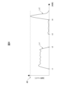
- FIG. 4 is a diagram for explaining abnormal load detection by the abnormal load detection device 10 ⁇ shown in FIG. 3, with the vertical axis indicating load torque and the horizontal axis indicating time.
- curve Lr1 indicates the load characteristics when the workpiece (object) is cut by the machine tool 20
- curve Lr2 indicates the load characteristics when an unexpected collision occurs while the workpiece is driven without being cut.
- curves Lr1 and Lr2 indicate load characteristics based on the actual load actually applied to the axis of the machine tool 20, which is the output of the actual load calculation unit 10c.
- Reference sign t1 indicates the time when cutting begins
- t2 indicates the time when cutting ends
- t3 indicates the time when axial movement of the machine tool 20 begins without cutting the workpiece
- t4 indicates the time when an unexpected collision occurs.
- the load torque increases over time from the cutting start time t1, then passes through a period of wavy fluctuations while the workpiece is cut, and decreases toward the cutting end time t2.
- abnormal load detection by the abnormal load detection device 10 ⁇ shown in Figure 3 is performed, for example, based on whether the load torque characteristic curve Lr1 exceeds a preset threshold value (alarm threshold value) AB1.
- the abnormal load detection device 10 ⁇ shown in FIG. 3 detects an abnormal load state by comparing a threshold value AB1 obtained by adding a torque value considered appropriate based on a predetermined offset to a torque value specific to the motor with the actual torque (the characteristic curve Lr1 of the load torque actually applied to the axis of the machine tool 20, which is the output of the actual load calculation unit 10c). That is, when a workpiece is cut by the machine tool 20, as shown by the curve Lr1 in FIG. 4, the load torque changes so as to increase with time from the cutting start time t1, and then decreases toward the cutting end time t2 after a wavy fluctuation period during which the workpiece is cut. At this time, the abnormal load detection device 10 ⁇ shown in FIG.
- the 3 detects an abnormal load based on, for example, whether the characteristic curve Lr1 of the load torque exceeds a preset threshold value AB1, so that the threshold value AB1 cannot be set to a small value, making it difficult to detect an abnormal load state with high sensitivity.
- FIG. 5 is a functional block diagram showing one example of an abnormal load detection device according to this embodiment
- FIG. 6 is a diagram for explaining abnormal load detection by the abnormal load detection device shown in FIG. 5.
- FIGS. 5 and 6 clearly show the differences from the example of the abnormal load detection device shown in FIGS. 3 and 4 described above.
- a machine tool controlled by the abnormal load detection device numbererical control device
- a machine tool that performs cutting processing of a workpiece is applied as an example of a machine tool controlled by the abnormal load detection device (numerical control device).
- the abnormal load detection device 10 ⁇ of this embodiment is roughly the same as the abnormal load detection device 10 ⁇ shown in FIG. 3, except that a predicted load calculation unit 10E and a differentiator 10F are added.
- the machining program 2 is stored, for example, in the non-volatile memory 114 in FIG. 2 and executed by the CPU 111.
- the abnormal load detection device (numerical control device) 10 ⁇ of this embodiment controls the motors 21 (servo motors 21x, 21y, 21z, 21A, 21B) of the machine tool 20 based on the machining program 2, and detects abnormal load conditions of the axes (motors).
- the abnormal load detection device 10 ⁇ includes a movement command generation unit 10A, a movement control unit 10B, an actual load calculation unit 10C, an abnormal load detector 10D, a predicted load calculation unit 10E, and a difference calculator 10F.
- the movement command generation unit 10A generates movement commands for the axes of the machine tool 20 based on the machining program 2, and the movement control unit 10B controls the movement of the axes of the machine tool 20 based on the movement commands generated by the movement command generation unit 10A.
- the actual load calculation unit 10C receives a movement command from the movement command generation unit 10A and also receives movement control information used to control the movement of the axes of the machine tool 20 from the movement control unit 10B, and calculates the actual load actually applied to the axes of the machine tool 20 based on these movement commands and movement control information.
- the abnormal load detector 10D detects an abnormal load state of the axes of the machine tool 20 based on the load prediction error, which is the output of the difference calculator 10F.
- the predicted load calculation unit 10E calculates the predicted load applied to the axis based on the machining program 2.
- the differencer 10F calculates a load prediction error, which is the difference between the predicted load on the axis of the machine tool 20 calculated by the predicted load calculation unit 10E and the actual load actually applied to the axis of the machine tool 20 calculated by the actual load calculation unit 10C, and outputs it to the abnormal load detector 10D.
- the predicted load calculation unit 10E calculates the predicted load by performing a simulation based on the machining program 2.
- the abnormal load detector 10D detects an abnormal load state of the axis of the machine tool 20 based on the load prediction error (LE1), which is the difference between the predicted load (LD1) and the actual load (LR1), which are the outputs of the differencer 10F.
- L1 load prediction error
- LD1 predicted load
- LR1 actual load
- FIG. 6 is a diagram for explaining abnormal load detection by the abnormal load detection device 10 ⁇ shown in FIG. 5, with the vertical axis indicating load torque and the horizontal axis indicating time.
- curve LR1 indicates the load characteristics (actual load) when a workpiece is cut by the machine tool 20
- curve LR2 indicates the load characteristics (actual load) when an unexpected collision occurs while the workpiece is being driven without being cut.
- the curve LD1 shows the output of the predicted load calculation unit 10E when the workpiece is cut by the machine tool 20, i.e., the characteristics of the predicted load applied to the axis calculated by performing a simulation based on the machining program 2.
- the curve LD2 shows the output (predicted load) of the predicted load calculation unit 10E when an unexpected collision occurs while the workpiece is driven without being cut. Note that the curve LD2, which is the output of the predicted load calculation unit 10E, is fixed to a constant value (zero) because it is the case when an unexpected collision occurs.
- holds. Furthermore, curve LE2 holds the relationship LE2
- LR2, because curve LD2 is fixed to zero.
- the abnormal load detector 10D detects the abnormal load state of the axis of machine tool 20 based on the load prediction error (LE1), which is the difference between the predicted load (LD1), which is the output of subtractor 10F, and the actual load (LR1), and therefore it is possible to improve the detection sensitivity of abnormal loads.
- L1 load prediction error
- a predetermined threshold alarm threshold
- AB2 a predetermined threshold
- the threshold AB2 can be set to a small value, making it possible to detect abnormal load conditions of the axes of the machine tool (20) with high sensitivity.
- the abnormal load detection device 10 ⁇ can also improve alarm sensitivity, for example, by generating an alarm based on the detection of an abnormal load condition.
- the predicted load calculation unit 10E needs to perform a simulation based on the machining program 2 to calculate the predicted load, for example, by directly analyzing the machining program 2 to predict the workpiece cutting start time (t1), and calculate the predicted load (predicted cutting load) from the cutting depth and cutting feed rate, etc., which are known from the machining program 2.
- the predicted cutting load can be calculated as [predicted cutting load] ⁇ [cutting depth] ⁇ [cutting feed rate].
- the predicted load calculation unit 10E can also receive, for example, information about the shape of the workpiece before cutting begins in advance, separately from the machining program 2, to more precisely calculate the predicted cutting load.
- information about the shape of the workpiece before cutting begins in advance is given as coordinates within the machine tool (20), and the tool position at which cutting begins and the positional relationship within the machine tool where the tool shape and the initial workpiece shape begin to collide can be calculated, allowing the predicted load calculation unit 10E to more precisely calculate the predicted cutting load.
- workpiece shape information can be obtained from the machining information of the previous step (the step immediately preceding), and used to calculate the predicted cutting load by the predicted load calculation unit 10E.
- the tool diameter of the tool used before the current machining and the path that the tool took on the workpiece can be used as machining information.
- the shape of the workpiece surface resulting from the rough machining can be simulated and the current cutting depth can be calculated at each machining position, allowing the predicted load calculation unit 10E to calculate the predicted cutting load more accurately.
- the information measured in that pre-process can also be used as shape information of the workpiece.
- the shape information of the workpiece can be obtained using a measuring unit such as the touch probe or vision sensor, and used to calculate the predicted cutting load by the predicted load calculation unit 10E.
- the value of the predicted cutting load can also be changed (modified) depending on the type and shape of the tool, or the material of the workpiece (workpiece material). For example, depending on the material of the workpiece, there are some that result in a light cutting load (aluminum) and some that result in a heavy cutting load (steel), so by performing a simulation to modify the cutting load depending on the material of the workpiece, the calculation of the predicted cutting load by the predicted load calculation unit 10E can be performed more accurately. Note that the calculation of the predicted cutting load (predicted load) by the predicted load calculation unit 10E described above is merely an example, and it goes without saying that various other changes and modifications are possible.
- the abnormal load detection method according to this embodiment may be configured as an abnormal load detection program executed by the CPU 111 in the numerical control device (abnormal load detection) 10 shown in FIG. 2, for example.
- the abnormal load detection program according to this embodiment may be stored in the non-volatile memory 114 in the numerical control device 10 shown in FIG. 2, for example.
- the abnormal load detection program according to the present embodiment described above may be provided by recording it on a computer-readable non-transitory recording medium or non-volatile semiconductor memory, or may be provided via a wired or wireless connection.
- Examples of computer-readable non-transitory recording media include optical disks such as CD-ROMs (Compact Disc Read Only Memory) and DVD-ROMs, or hard disk devices.
- Examples of non-volatile semiconductor memory include PROMs (Programmable Read Only Memory) and flash memories.
- distribution from a server device may be via a wired or wireless LAN (Local Area Network), or a WAN such as the Internet.
- the abnormal load detection device, abnormal load detection method, and abnormal load detection program according to this embodiment can improve the detection sensitivity of abnormal loads.
- An abnormal load detection device (10 ⁇ ) for detecting an abnormal load state of an axis in a machine tool (20) having at least one axis comprising: a movement command generating unit (10A) that generates movement commands for the axes based on a machining program (2); a predicted load calculation unit (10E) for calculating a predicted load applied to the axis based on the machining program (2); A movement control unit (10B) that controls the movement of the axis based on the movement command; an actual load calculation unit (10C) that calculates an actual load actually applied to the axis based on the movement command and movement control information used for the movement control of the axis; A difference calculator (10F) for calculating a load prediction error which is a difference between the predicted load and the actual load; and an abnormal load detector (10D) that detects an abnormal load state of the shaft based on the load prediction error.
- a movement command generating unit (10A) that generates movement commands for the axes based on a machining program (2)
- the machine tool (20) is a machine tool that performs cutting processing on a workpiece, The abnormal load detection device (10 ⁇ ) detects an abnormal load state of the cutting shaft.
- [Appendix 5] The abnormal load detection device according to claim 3 or 4, wherein the predicted load calculation unit (10E) receives shape information of the workpiece before cutting is started in advance, separately from the machining program (2), and calculates the predicted cutting load more precisely.
- [Appendix 6] The abnormal load detection device according to any one of Appendix 3 to Appendix 5, wherein the predicted load calculation unit (10E) obtains shape information of the workpiece from processing information of the immediately preceding process when the processing is divided into several processes from rough processing to finishing processing, and uses the information to calculate the predicted cutting load.
- [Appendix 7] The abnormal load detection device according to any one of Appendix 3 to Appendix 6, wherein, when the machine tool (20) repeatedly cuts the same type of workpiece, the predicted load calculation unit (10E) stores actual load information of the workpiece in memory from processing information of the previous workpiece, and compares the stored actual load information of the workpiece with the actual load information of the current workpiece to more precisely calculate the predicted cutting load.
- the predictive load calculation unit (10E) uses information measured in the pre-processing process as shape information of the workpiece.
- a method for detecting an abnormal load condition of an axis in a machine tool (20) having at least one axis comprising: a movement command generating step of generating a movement command for the axis based on a machining program (2); a predicted load calculation step of calculating a predicted load applied to the axis based on the machining program (2); a movement control step of controlling the movement of the axis based on the movement command; an actual load calculation step of calculating an actual load actually applied to the axis based on the movement command and movement control information used for movement control of the axis; a difference calculation step of calculating a load prediction error, which is a difference between the predicted load and the actual load; an abnormal load detection step of detecting an abnormal load state of the shaft based on the load prediction error.
- An abnormal load detection program for detecting an abnormal load state of an axis in a machine tool (20) having at least one axis, comprising: A processing unit includes: a movement command generating step of generating a movement command for the axis based on a machining program (2); a predicted load calculation step of calculating a predicted load applied to the axis based on the machining program (2); a movement control step of controlling the movement of the axis based on the movement command; an actual load calculation step of calculating an actual load actually applied to the axis based on the movement command and movement control information used for movement control of the axis; a difference calculation step of calculating a load prediction error, which is a difference between the predicted load and the actual load; an abnormal load detection step of detecting an abnormal load state of the shaft based on the load prediction error,
Landscapes
- Engineering & Computer Science (AREA)
- Human Computer Interaction (AREA)
- Manufacturing & Machinery (AREA)
- Physics & Mathematics (AREA)
- General Physics & Mathematics (AREA)
- Automation & Control Theory (AREA)
- Numerical Control (AREA)
Priority Applications (4)
| Application Number | Priority Date | Filing Date | Title |
|---|---|---|---|
| JP2025520331A JPWO2024236764A1 (https=) | 2023-05-17 | 2023-05-17 | |
| CN202380097954.6A CN121152707A (zh) | 2023-05-17 | 2023-05-17 | 异常负荷检测装置、异常负荷检测方法以及异常负荷检测程序 |
| DE112023005963.2T DE112023005963T5 (de) | 2023-05-17 | 2023-05-17 | Vorrichtung zur erkennung eines abnormalen lastzustands, verfahren zur erkennung eines abnormalen lastzustands und programm zur erkennung eines abnormalen lastzustands |
| PCT/JP2023/018421 WO2024236764A1 (ja) | 2023-05-17 | 2023-05-17 | 異常負荷検出装置、異常負荷検出方法および異常負荷検出プログラム |
Applications Claiming Priority (1)
| Application Number | Priority Date | Filing Date | Title |
|---|---|---|---|
| PCT/JP2023/018421 WO2024236764A1 (ja) | 2023-05-17 | 2023-05-17 | 異常負荷検出装置、異常負荷検出方法および異常負荷検出プログラム |
Publications (1)
| Publication Number | Publication Date |
|---|---|
| WO2024236764A1 true WO2024236764A1 (ja) | 2024-11-21 |
Family
ID=93519539
Family Applications (1)
| Application Number | Title | Priority Date | Filing Date |
|---|---|---|---|
| PCT/JP2023/018421 Ceased WO2024236764A1 (ja) | 2023-05-17 | 2023-05-17 | 異常負荷検出装置、異常負荷検出方法および異常負荷検出プログラム |
Country Status (4)
| Country | Link |
|---|---|
| JP (1) | JPWO2024236764A1 (https=) |
| CN (1) | CN121152707A (https=) |
| DE (1) | DE112023005963T5 (https=) |
| WO (1) | WO2024236764A1 (https=) |
Citations (4)
| Publication number | Priority date | Publication date | Assignee | Title |
|---|---|---|---|---|
| JPH0751995A (ja) * | 1993-08-06 | 1995-02-28 | Fanuc Ltd | 加工負荷監視方式 |
| JPH0885044A (ja) * | 1994-09-19 | 1996-04-02 | Fanuc Ltd | 加工負荷監視方式 |
| JP2004126956A (ja) * | 2002-10-02 | 2004-04-22 | Okuma Corp | 数値制御装置 |
| JP2020199611A (ja) * | 2019-06-12 | 2020-12-17 | ファナック株式会社 | 工作機械および工作機械の制御方法 |
-
2023
- 2023-05-17 JP JP2025520331A patent/JPWO2024236764A1/ja active Pending
- 2023-05-17 WO PCT/JP2023/018421 patent/WO2024236764A1/ja not_active Ceased
- 2023-05-17 DE DE112023005963.2T patent/DE112023005963T5/de active Pending
- 2023-05-17 CN CN202380097954.6A patent/CN121152707A/zh active Pending
Patent Citations (4)
| Publication number | Priority date | Publication date | Assignee | Title |
|---|---|---|---|---|
| JPH0751995A (ja) * | 1993-08-06 | 1995-02-28 | Fanuc Ltd | 加工負荷監視方式 |
| JPH0885044A (ja) * | 1994-09-19 | 1996-04-02 | Fanuc Ltd | 加工負荷監視方式 |
| JP2004126956A (ja) * | 2002-10-02 | 2004-04-22 | Okuma Corp | 数値制御装置 |
| JP2020199611A (ja) * | 2019-06-12 | 2020-12-17 | ファナック株式会社 | 工作機械および工作機械の制御方法 |
Also Published As
| Publication number | Publication date |
|---|---|
| CN121152707A (zh) | 2025-12-16 |
| JPWO2024236764A1 (https=) | 2024-11-21 |
| DE112023005963T5 (de) | 2026-01-29 |
Similar Documents
| Publication | Publication Date | Title |
|---|---|---|
| CN110297461B (zh) | 异常检测装置 | |
| KR100299412B1 (ko) | 가공처리장치 | |
| KR100579083B1 (ko) | 공작기계의 공구 이상 검출장치 및 검출방법 | |
| KR102256424B1 (ko) | 에러 전파의 추정 방법 | |
| JP2020123191A (ja) | 数値制御システム | |
| JP4593142B2 (ja) | 被加工物をコンピュータ制御で製造するシステムおよび製造される被加工物を測定する方法 | |
| JP2011118840A (ja) | モータ負荷トルク測定機能を有する数値制御装置 | |
| JP2020116666A (ja) | 工作機械の工具管理システム | |
| JP7779931B2 (ja) | 産業機械の変化の推定装置 | |
| JP6618656B1 (ja) | 保守支援システム、数値制御装置および保守支援システムの制御方法 | |
| JP6034835B2 (ja) | サイクルタイムを短縮するための情報を提示する数値制御装置 | |
| KR100548874B1 (ko) | 공구의 날 빠짐 검지기능을 갖는 수치제어장치 | |
| KR20190106241A (ko) | 공작기계 및 공작기계의 제어방법 | |
| WO2024236764A1 (ja) | 異常負荷検出装置、異常負荷検出方法および異常負荷検出プログラム | |
| JP7504687B2 (ja) | 切削加工支援システム | |
| KR101896291B1 (ko) | 공작 기계의 가공경로 보정방법 | |
| JP2020157397A (ja) | 工具の破損予測方法 | |
| EP4291960B1 (en) | Methods and systems for adapting a feed rate of a feed control on numerically controlled machine tools | |
| EP4636516A1 (en) | A method of generating parameters applied for machining a workpiece performed by a machine tool | |
| CN112987649A (zh) | 工作母机加工信息即时呈现方法与工作母机即时呈现系统 | |
| Tu et al. | Review of sensor-based approach to reliable high speed machining at boeing–A tribute to Jan Jeppsson | |
| KR100655296B1 (ko) | 주축부하의 공구이상 검출장치 및 방법 | |
| WO2024180769A1 (ja) | シミュレーション装置およびコンピュータ読み取り可能な記憶媒体 | |
| WO2025144894A1 (en) | System and method for automatic data extraction and labelling for supervised machine learning to automate cnc manufacturing | |
| Dahake et al. | Prototype Development of Milling Machine Using CAD/CAM: A Review |
Legal Events
| Date | Code | Title | Description |
|---|---|---|---|
| 121 | Ep: the epo has been informed by wipo that ep was designated in this application |
Ref document number: 23937506 Country of ref document: EP Kind code of ref document: A1 |
|
| WWE | Wipo information: entry into national phase |
Ref document number: 2025520331 Country of ref document: JP |
|
| WWE | Wipo information: entry into national phase |
Ref document number: 112023005963 Country of ref document: DE |
|
| WWP | Wipo information: published in national office |
Ref document number: 112023005963 Country of ref document: DE |